1
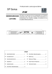
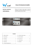
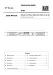
R
DUAL CHANNEL
POWER AMPLIFIERS
DPA 2000
DPA 3200
DPA 4500
DPA 5000
Owner’s Manual
CH 1
I
CH 2
PROTECT
-6
-6
-3
-10
-3
-10
CLIP
POWER
O
-15
-1
-30
-80
-15
SIGNAL
-1
-30
0dB
-80
POWER
0dB
Class H Professional Power Amplifier
PROTECT
POWER
CLIP
SIGNAL
-6
I
-6
-3
-10
-3
-10
POWER
O
CH -15
1
-15
-1
-30
-80
-1
-30
0dB
-80
CH 2
Class H Professional Power Amplifier
0dB
PROTECT
POWER
CLIP
SIGNAL
-6
I
-6
-3
-10
-3
-10
POWER
O
CH -15
1
-15
-1
-30
-80
-1
-30
0dB
-80
CH 2
Class H Professional Power Amplifier
0dB
PROTECT
POWER
CLIP
SIGNAL
-6
I
-10
-6
-3
-10
-3
POWER
O
CH -15
1
-15
-1
-30
-80
0dB
-1
-30
-80
0dB
CH 2
Class H Professional Power Amplifier
Explanation of Graphical Symbols
The lightning flash with arrowhead
symbol within an equilateral triangle is
intended to alert the user to the presence
of uninsulated “dangerous voltage”
within the product’s enclosure that may
be of sufficient magnitude to constitute a
risk of electric shock to persons.
CAUTION
RISK OF ELECTRIC SHOCK
DO NOT OPEN
CAUTION: TO REDUCE THE RISK OF
ELECTRIC SHOCK, DO NOT REMOVE
COVER (OR BACK). NO USER-SERVICEABLE
PARTS INSIDE. REFER SERVICING TO
QUALIFIED SERVICE PERSONNEL.
The exclamation point within an
equilateral triangle is intended to alert the
user to the presence of important
operating and maintenance (servicing)
instructions in the literature accompanying the product.
The above warning is located on the top of the unit
IMPORTANT SAFETY INSTRUCTIONS
1
2
3
4
5
6
7
8
Read these instructions.
Keep these instructions.
Heed all warnings.
Follow all instructions.
Do not use this apparatus near water.
Clean only with dry cloth.
Do not block any ventilation openings. Install in accordance
with the manufacturer’s instructions.
Do not install near any heat sources such as radiators, heat
registers, stoves, or other apparatus (including amplifiers)
that produce heat.
Do not defeat the safety purpose of the polarized or grounding-type plug.
10 Protect the power cord from being walked on or pinched
particularly at plugs, convenience receptacles, and the point
where they exit from the apparatus.
11 Only use attachments/accessories specified by the manufacturer.
12
13
.
Unplug this apparatus during lightning
unused for long periods of time.
Refer all servicing to qualified service personnel.
Servicing is required when the apparatus has been
damaged in any way, such as power supply cord or
plug is damaged, liquid has been spilled or objects
have fallen into the apparatus, the apparatus has been
exposed to rain or moisture, does not operate normally,
or has been dropped.
9
2
WARNING
TO REDUCE THE RISK OF FIRE OR ELECTRIC SHOCK, DO
NOT EXPOSE THIS APPARATUS TO RAIN OR MOISTURE.
Precautions
—
For safe operation
—
WARNING
Installation
Do not modify the unit. Doing so is a fire and electrical
shock hazard.
Connect this unit’s power cord only to an AC outlet of the
type stated in this Owner’s Manual or as marked on the unit.
Failure to do so is a fire and electrical shock hazard.
Do not allow water to enter this unit or allow the unit to
become wet. Fire or electrical shock may result.
Do not place a container with liquid or small metal objects on
top of this unit. Liquid or metal objects inside this unit are a
fire and electrical shock hazard.
Do not place heavy objects, including this unit, on top of the
power cord. A damaged power cord is a fire and electrical
shock hazard. In particular, be careful not to place heavy
objects on a power cord covered by a carpet.
If lightning begins to occur, turn off the power switch of
the unit as soon as possible, and unplug the power cable
plug from the electrical outlet.
Operation
Do not scratch, bend, twist, pull, or heat the power cord. A
damaged power cord is a fire and electrical shock hazard.
Do not remove the unit’s cover. You could receive an
electrical shock. If you think internal inspection, maintenance,
or repair is necessary, contact your dealer.
If there is a possibility of lightning, do not touch the power
cable plug if it is still connected. Doing so may be an
electrical shock hazard.
In case an abnormality occurs during operation
If the power cord is damaged (i.e., cut or a bare wire is
exposed), ask your dealer for a replacement. Using the unit
with a damaged power cord is a fire and electrical shock
hazard.
Should this unit be dropped or the cabinet be damaged, turn
the power switch off, remove the power plug from the AC
outlet, and contact your dealer. If you continue using the
unit without heeding this instruction, fire or electrical
shock may result.
If you notice any abnormality, such as smoke, odor, or
noise, or if a foreign object or liquid gets inside the unit,
turn it off immediately. Remove the power cord from the
AC outlet. Consult your dealer for repair. Using the unit in
this condition is a fire and electrical shock hazard.
CAUTION
Installation
Keep this unit away from the following locations:
- Locations exposed to oil splashes or steam, such as near
cooking stoves, humidifiers, etc.
- Unstable surfaces, such as a wobbly table or slope.
- Locations exposed to excessive heat, such as inside a car
with all the windows closed, or places that receive direct
sunlight.
- Locations subject to excessive humidity or dust
accumulation.
Do not place the power cord close to a heater. It may melt,
causing fire or electrical shock.
Hold the power cord plug when disconnecting it from an AC
outlet. Never pull the cord. A damaged power cord is a
potential fire and electrical shock hazard.
Do not touch the power plug with wet hands. Doing so is a
potential electrical shock hazard.
This unit has ventilation holes at the front, rear & top to
prevent the internal temperature rising too high. Do not block
them.
Blocked ventilation holes are a fire hazard.
In particular, do not
- place the unit on its side or upside down.
- place the unit in any poorly-ventilated location such as a
bookcase or closet (other than on the dedicated rack).
- cover the unit with a table cloth or place it on a carpet or
bed.
Allow enough free space around the unit for normal
ventilation.
This should be: 5 cm at the sides, 10 cm behind, and 10 cm
above.
If the airflow is not adequate, the unit will heat up inside and
may cause a fire.
To relocate the unit, turn the power switch off, remove the
power plug from the AC outlet, and remove all connecting
cables. Damaged cables may cause fire or electrical shock.
Operation
Use only thick speaker cables when connecting speakers to
amplifier outputs. Use of cables type 40/36 or thicker is
recommended for connecting low impedance speakers to
avoid power loss in the cables, as heavy current flows
through the cables. Using other types of cables is a fire
hazard.
Turn off all musical instruments, audio equipment, and
speakers when connecting to this unit. Use the correct
connecting cables and connect as specified.
Always lower the volume control to minimum before
turning on the power to this unit. A sudden blast of sound
may damage your hearing.
Do not use this amplifier for any purpose other than
driving loudspeakers.
If you know you will not use this unit for a long period of
time, such as when going on vacation, remove the power
plug from the AC outlet. Leaving it connected is a
potential fire hazard.
When operating amplifier on a generator, make sure it
is switched “OFF” till generator voltages has stabilized
& then only switch “ON” amplifier.
Be sure of proper impedance of 2/4/8 ohm when used for
STEREO/PARALLEL configuration & 4/8 ohm
recommended when used in BRIDGE mode.
3
Tips for Safe Operation
The 3 core AC mains cable should be terminated with this
AC mains plug by connecting brown/red wire on live pin
(L), black/blue wire on neutral pin (N) and yellow/green
wire on earth pin (E).
For 2 ohm/4 ohm applications, it is recommended
to use speakon connectors only. Use of cable 40/36
or thicker is recommended to prevent power
losses.
The amplifier must be connected to an AC earthed mains
outlet that can delivered the maximum power required.
The use of extension cables or adaptors should be avoided
as this can jeoparadize correct power delivery to the
amplifier.
The level of input signal should not exceed the
specified input sensitivities. Excessive input signal
levels result in over driving of input circuit which
leads to saturated / distorted output at speaker
terminals.
All connections must only be carried out or changed
with the amplifier switched OFF. Ensure proper
impedance matching while in use for BRIDGE mode
applications. For continuous safe operation, resultant
impedance of the speakers 8 ohm/4 ohm is recommended.
Do not operate the amplifier with continuously
blinking CLIP LED. The respective volume control
of the channels must be adjusted so that the output
level does not clip and distort. Do not obstruct the
front or back of the amplifier for necessary intake of
air.
4
Contents
Page No.
Features / General Description of Product....................................................................6
Front Panel Controls & Features...................................................................................7
Rear Panel Controls & Features....................................................................................8
Input-Output Connections...........................................................................................10
Setup & Operations.....................................................................................................11
Typical Applications....................................................................................................14
Protections & Installations..........................................................................................17
Trouble Shooting.........................................................................................................18
Specifications..............................................................................................................20
Notes............................................................................................................................23
5
Thank you for your purchase of the STUDIOMASTER DPA Series power amplifiers. These amplifiers fully incorporate
STUDIOMASTER’s renowned technology and offers high reliability, rock solid stability and superb acoustic
characteristics.
*Please retain original packing should you have to return the unit for the repairs.
Features / General Description of Product
Rugged 19” rack mountable design of chassis.
High current torroidal transformer which provides excellent regulation and minimized hum & noise.
Low THD and high damping factor for excellent sound quality.
Extensive protection circuitry for Overheat, Overload, DC, Output short circuit.
Indicator LEDs for Signal, Clip, Protect, Power ON, Mode Selection.
Output termination on 4 way speakon Connectors and Binding posts for each channels.
Limiter circuit protects the amplifier and speaker from being over driven because of high input level signal.
Designed with a sophisticated VHF limiter that reduces the risk of HF stress, and protects your speakers, particularly
HF units.
Balanced / Unbalanced input signal through parallel XLR in both channels.
Slide Switches For 1) Mode selection ( Mono / Stereo / Bridge)
2) Sensitivity ( 0.775 V / 1V / 1.4 V)
3) Low - cut (30Hz) (ON / OFF )
4) Ground Lift ( GND / LIFT)
5) Limiter
6) HF Limiter
Twin tunnel cooling with front to back airflow.
This owners Manual covers 4 models, DPA 2000, DPA 3200, DPA 4500 & DPA 5000 power amplifiers. Please read through
this manual carefully before beginning use, so that you will be able to take full advantage of amplifier’s superlative features
and enjoy trouble free operation for years to come. After reading through the manual, please store it in a safe place.
6
CH 1
I
CH 2
PROTECT
-6
-6
-3
-10
-3
-10
CLIP
POWER
-15
O
SIGNAL
-1
-30
-80
-1
-30
0dB
3
-15
-80
POWER
4
1
4
2
5
6
0dB
Class H Professional Power Amplifier
3
5
6
PROTECT
POWER
CLIP
SIGNAL
-6
I
-6
-3
-10
-3
-10
POWER
O
CH -15
1
-15
-1
-30
-80
1
6
5
4
3
-1
-30
0dB
-80
2
CH 2
Class H Professional Power Amplifier
0dB
3
6
4
5
Front Panel Controls & Features
1
2
3
4
5
6
Master switch
Switches the unit on and off, interrupting both phases.
Power ON indicator light
When lit, this blue LED indicates that amplifier is ON.
Volume control
Used for adjusting the volume of the channel.
Signal indicator
Green LED that indicates the presence of the signal in the final stage. It lights up with signals higher than - 20dB.
Clip indicator
This red LED lights up to indicate that the internal limiter has been activated to eliminate clip. When the limiter is
activated, it indicates that the maximum amplification has been reached. When it lights up continuously, this means
there is an excessive signal input.
Protect indicator
Red LED that indicates the mute status of the channel and is lit for the following reasons:
switch on delay (3 seconds), presence of continuous voltage on the channel output, short circuit, thermal protection of
the channel, thermal protection of the transformer.
7
DPA-2000
2
1
8
10
14
5
3
13
T16A 250VAC
0 9 0 3 0 1 0 8 0
LIMITER
30Hz
LOWCUT
9
2
DPA-3200,4500 & 5000
1
2
INPUT
GROUND
LIFT
HF
PROTECTION
12
11
15
4
1
8
10
14
9
7
6
5
3
LIMITER
30Hz
LOWCUT
INPUT
GROUND
LIFT
HF
PROTECTION
0 9 0 3 0 1 0 8 0
9
2
1
12
11
15
13
4
9
6
7
Rear Panel Controls & Features
1
Balanced XLR input
This XLR connector takes the signal (balanced/unbalanced) for driving the channel. If the signal is unbalanced, pin 2
can be used for the signal and pin 3 connected to the earth.
2
Link Out
To Cascade amplifiers.
3
CH 1 output speakon connector
Use this connector for picking up the amplified signal of CH 1 and signal for bridged configuration.
4
CH 2 output speakon connector
Use this connector for picking up the amplified signal of CH 2.
5
CH 1 output binding post.
Use this connector for picking up the amplified signal of CH 1 and signal for bridged configuration.
6
CH 2 output binding post.
Use this connector for picking up the amplified signal of CH 2.
7
Power cable
Use this cable for supplying power to unit.
8
Configuration switch
This three way switch configures the amplifier for the three working modes: parallel, stereo and bridge.
9
Air Outlet grill
The air sucked from the front grills is thrown out from these grills. Do not obstruct the grills. The air filter
whenever necessary.
8
10
Sensitivity
This switch is used to select sensitivity to either 0.775V, 1V or 1.2V depending on the source.
11
Ground lift
Allows circuit & chassis grounds to be separated in case of ground loops.
12
Low cut
Low cut switch filters the low frequencies from the input signal. Cut off frequency is 30 Hz when it is selected. The
filter protects the cone of the speakers against unwanted and inaudible low frequencies.
13
Fuse
Mains fuse secures the amplifier & wires against defects, Replace this only with the same type & rating.
14
Limiter
This switch activates limiter when in ON position. The limiter prevents distortion of the output level when its gets
overloaded. When the output level exceeds its maximum, an internal adjustment will be made to prevent overloading.
The limiter is specially designed to safeguard connected full-range speakers. The high tone piezo drivers of these
speakers are now protected against distortion and harmonic signals which are the result of over steering the amplifier.
When the amplifier is used as a subwoofer amplifier then the limiter has to be switched off to set the extra “punch”.
15
HF Limiter
It is a protection for the amplifier against HF. In case there is high amplitude HF signal at the output, it shuts down
the amplifier thus protecting the internal circuitry and HF drivers of a speaker system.
Presence of prolonged, large amplitude, high frequency output can damage the speakers as well as the internal circuit
of the amplifier. The HF limiter circuit continuously monitors the output and shuts down the amplifier, if the high
frequency persists for more than 10-15 seconds. The HF limiter has no effect on normal music.
9
Input-Output Connections
FIG. 1
BALANCED INPUT CONNECTIONS
XLR
UNBALANCED INPUT CONNECTIONS
XLR
FIG. 3
PARALLEL / STEREO OUTPUT CONNECTIONS
FIG. 4
BRIDGE OUTPUT CONNECTIONS
(CH 1 OUTPUT CONNECTOR)
FIG. 5
PARALLEL / STEREO BINDING POST CONNECTIONS
FIG. 6
BRIDGE MODE BINDING POST CONNECTIONS
-VE OUTPUT
+VE OUTPUT
+VE OUTPUT
-VE OUTPUT
10
FIG. 2
-STEREO
-STEREO
CH1 OUTBINDING POST
CH1 OUTBINDING POST
+STEREO/+BRIDGE
+VE OUTPUT
+STEREO/+BRIDGE
+STEREO/-BRIDGE
-VE OUTPUT
+STEREO/-BRIDGE
CH2 OUTBINDING POST
CH2 OUTBINDING POST
-STEREO
-STEREO
Setup & Operation
Stereo Mode Configuration
0 9 0 3 0 1 0 8 0
LIMITER
30Hz
LOWCUT
INPUT
GROUND
LIFT
HF
PROTECTION
SPEAKER SYSTEM
(IMP 8Ω / 4Ω / 2Ω)
T16A 250VAC
SPEAKER SYSTEM
(IMP 8Ω / 4Ω / 2Ω)
MICROPHONES
WIRELESS
MICROPHONE
SERIES
CD PLAYER
P A MIXER
In STEREO mode, both channels 1 & 2 are fully independent of each other. The balanced / unbalanced inputs can be
connected either to a stereo signal source or two independent mono signal sources. Each channel can separately drive
loudspeaker loads of 8 ohm or 4 ohm or 2 ohm.
Connect the Left and Right outputs of a mixer to a channel
1 and 2 inputs of the amplifier respectively. Inputs can be
wired as per fig.1 & 2 (Input Connections for Balanced
and Unbalanced Mode)
Connect a speaker system (8 ohm / 4 ohm / 2 ohm) on the
output terminal of each channel.
Either use the speakon connector & wire these as per fig.3
(Output Connections for Stereo / Parallel Mode) or use
Binding Post as per wire diagram of fig. 5.
To select STEREO mode, keep the slide switch,
provided at rear panel, in STEREO position.
Adjust the individual volume controls of each channel
on the front panel to obtain the desired output level.
The level indicator LEDs glow to indicate the
presence of signal at the output terminals.
11
Setup & Operation
Parallel Mode Configuration
0 9 0 3 0 1 0 8 0
LIMITER
30Hz
LOWCUT
INPUT
GROUND
LIFT
HF
PROTECTION
SPEAKER SYSTEM
(IMP 8Ω / 4Ω / 2Ω)
T16A 250VAC
SPEAKER SYSTEM
(IMP 8Ω / 4Ω / 2Ω)
MICROPHONES
‘Y’- Cable
WIRELESS
MICROPHONE
SERIES
CD PLAYER
P A MIXER
Note:- ‘Y’ cable to be used to make mono cable or use mono output of mixer.
When operating in PARALLEL mode, the signal source should be connected to the balanced / unbalanced inputs of
channel 1 only. Both channels provide similar outputs to their respective loudspeakers. Each channel can separately drive
loudspeaker loads of 8 ohm or 4 ohm or 2 ohm.
Connect the line output of a mixer to a channel 1 input of
the amplifier. Inputs can be wired as per fig.1 & 2 (Input
Connections for Balanced and Unbalanced Mode)
Connect a speaker system (8 ohm / 4 ohm / 2 ohm) on the
output terminal of each channel. Either use the speakon
connector & wire these as per fig.3 (Output Connections
for Stereo / Parallel Mode) or use Binding Post as per wire
diagram of Fig. 5.
12
TO select PARALLEL mode, keep the slide switch,
provided at rear panel in parallel position.
The desired output levels for both the channels are
adjustable by volume controls of respective channels.
The level indicator LEDs glow to indicate the
presence of signal at the output terminals.
Setup & Operation
Bridge Mode Configuration
0 9 0 3 0 1 0 8 0
30Hz
LOWCUT
INPUT
GROUND
LIFT
HF
PROTECTION
SPEAKER SYSTEM
(IMP 8Ω / 4Ω)
T16A 250VAC
LIMITER
MICROPHONES
‘Y’- Cable
WIRELESS
MICROPHONE
SERIES
CD PLAYER
P A MIXER
Note:- ‘Y’ cable to be used to make mono cable or use mono output of mixer.
For BRIDGE mode operation, the signal source should be connected to the balanced / unbalanced inputs of channel 1 only.
In this mode, the combined power output of both channels should be connected to a single loudspeaker load. The combined
loudspeaker load should not go below 4 ohm.
Connect the line output of a mixer to a channel 1 input of
the amplifier. Input can be wired as per fig.1 & 2 (Input
Connections for Balanced and Unbalanced Mode)
To select BRIDGE mode, keep the slide switch,
provided at rear panel, in Bridge position and ensure
that the bridge LED located on the back panel glows.
Connect a speaker system (8 ohm/4 ohm) on the speakon
output of channel 1 only. Either use the speakon
connectors and wire these as per fig.4 (Output Connections
for Bridge Mode) or Binding Post connections as per fig. 6.
The desired output levels of both the channels are
adjustable by volume control of channel 1 only.
The level indicator LEDs glow to indicate the
presence of signal at the output terminals.
13
Typical Applications
Stereo Mix Plus Subwoofers
AMPLIFIER 1 (Stereo Mode)
(Fullrange
2/3 way system)
(Fullrange
2/3 way system)
30Hz
LOWCUT
INPUT
GROUND
LIFT
HF
PROTECTION
T16A 250VAC
0 9 0 3 0 1 0 8 0
LIMITER
AMPLIFIER 2 (Bridge Mode)
INPUT
GROUND
LIFT
HF
PROTECTION
T16A 250VAC
0 9 0 3 0 1 0 8 0
LIMITER
30Hz
LOWCUT
Sub Output
Hi Output
ACTIVE CROSSOVER
Input
Sub Output
(Subwoofer)
30Hz
LOW CUT
MICROPHONES
WIRELESS
MICROPHONE
STEREO KEYBOARD
SERIES
HEADPHONE
P A MIXER
Connect the left and Right outputs of the Audio mixing
console to the respective inputs of the Active Crossover.
Connect the Left and Right High frequency output of the
active crossover to the respective input channels 1 & 2 of
amplifier 1. Inputs can be wired as per fig. 1 & 2 (Input
Connections for Balanced and Unbalanced Mode)
One number of full range loudspeaker system can be
connected to each of the channels of amplifier 1. The
output connectors should be wired as per fig. 3 (Output
Connections for Stereo / Parallel Mode) for speakon or
fig. 5 for Binding Post connections.
Amplifier 1 will be used in stereo mode. Keep the slide
switch of amplifier 1 in stereo position.
Feed the Left low frequency output signal of the crossover
to channel 1 input of amplifier 2. Inputs can be wired as
per fig. 1 & 2 (Input Connections for Balanced and
Unbalanced Mode)
14
The high powered subwoofer system can be connected to the channel 1output of amplifier 2. Output
speakon connectors can be wired as per fig. 4 (Output
Connections for Bridge Mode) or fig. 6 for Binding
Post connections.
Amplifier 2 will be used in bridge mode. Keep the
slide switch of amplifier 2 to BRIDGE position to
activate bridge mode as indicated by the glow of
BRIDGE LED, make sure that LOW CUT switch is
in OFF position.
Finally adjust the volume control of channel 1 & 2 in
amplifier 1 to control the level of their respective
position to get desired power. Also, adjust the volume
control of channel 1 in amplifier 2 to control the
levels of their respective position to get desired
power.
Typical Applications
Stereo Mode - Cascade Configuration
AMPLIFIER 2 (Stereo Mode)
(Resultant Imp = not < 2Ω)
(Resultant Imp = not < 2Ω)
30Hz
LOWCUT
INPUT
GROUND
LIFT
HF
PROTECTION
T16A 250VAC
0 9 0 3 0 1 0 8 0
LIMITER
(Resultant Imp = not < 2Ω)
(Resultant Imp = not < 2Ω)
AMPLIFIER 1 (Stereo Mode)
INPUT
GROUND
LIFT
HF
PROTECTION
T16A 250VAC
0 9 0 3 0 1 0 8 0
LIMITER
30Hz
LOWCUT
MICROPHONES
WIRELESS
MICROPHONE
SERIES
CD PLAYER
P A MIXER
Connect the Left and Right outputs of the Audio mixing
console to the channel 1 & 2 (XLR) of amplifier 1.
Connect CH 1 LINK OUT input of amplifier 1 to CH 1 IN
(XLR) of amplifier 2. Similarly make connections for
CH 2.
Speakers can be connected to respective output but
ensure that resultant impedance is not less than 2 ohms.
The input can be wired fig. 1 & 2 (Input Connections for
Balanced and Unbalanced Mode)
The speaker connections of amplifier 2 are done in a
similar way as for amplifier 1.
Amplifier 1 and 2 will be used in stereo mode.
Keep the slide switch of amplifier 1and 2 in stereo
position.
Adjust the volume controls of channel 1 & 2 of both
the amplifiers to control the levels of their respective
Speakers.
Finally any adjustments in the total quantity of the
sound, if required, can be made from the audio
mixing console.
15
Typical Applications
Parallel Mode - High Power Dual Channel Configuration
SPEAKER
SPEAKER
AMPLIFIER 2 (Parallel Mode)
LIMITER
30Hz
LOWCUT
SPEAKER
INPUT
GROUND
LIFT
HF
PROTECTION
T16A 250VAC
0 9 0 3 0 1 0 8 0
SPEAKER
AMPLIFIER 1 (Parallel Mode)
LEFT
BACK
INPUT
GROUND
LIFT
HF
PROTECTION
T16A 250VAC
0 9 0 3 0 1 0 8 0
LIMITER
30Hz
LOWCUT
MICROPHONES
WIRELESS
MICROPHONE
STEREO KEYBOARD
SERIES
HEADPHONE
P A MIXER
SPEAKER
SPEAKER
AMPLIFIER 3 (Parallel Mode)
LIMITER
30Hz
LOWCUT
INPUT
GROUND
LIFT
HF
PROTECTION
T16A 250VAC
0 9 0 3 0 1 0 8 0
RIGHT
BACK
SPEAKER
SPEAKER
AMPLIFIER 4 (Parallel Mode)
30Hz
LOWCUT
INPUT
GROUND
LIFT
Connect the left line output of the Audio mixing console to
the channel 1 input (XLR) of amplifier 1.
Connect CH 1 LINK OUT (XLR) of amplifier 1 to the
channel 1 input (XLR) of amplifier 2. The XLR input can
be wired as per fig. 1 & 2 (Input Connections for Balanced
and Unbalanced Mode)
The Left speaker stack compromises of four nos. speaker
systems. Each speaker is individually connected to the four
speaker outputs available from amplifier 1(channel 1 & 2)
and amplifier 2 (channel 1 & 2).
Output speakon connectors to be wired as per fig. 3
(Output Connections for Stereo/ Parrallel Mode) or fig. 5
for Binding Post connection.
Amplifier 1 & 2 will be used in Parallel mode.
16
HF
PROTECTION
T16A 250VAC
0 9 0 3 0 1 0 8 0
LIMITER
Keep the slide switch of amplifier 1 and 2 in Parallel
position.
Similarly, connect the Right line output of the Audio
mixing console to the channel 1 input (XLR) of
amplifier 3. Also connect CH 1 LINK OUT (XLR)
of amplifier 3 to the channel 1 input (XLR) of
amplifier 4.
The Right speaker stack’s connections are done in a
similar way as for left speaker stack’s connections.
Amplifier 3 and 4 will also be used in Parallel mode.
Adjust the volume controls of both the channel in all
the four amplifier to control the levels of their
respective speakers.
Finally any adjustments in the total quality of the
sound, if required, can be made from the audio
mixing console.
Protections & Installations
Thermal Protection
Output Devices
Due to excessive heating of output devices, the thermal
protection circuits brings the audio signal to mute status.
Onset of thermal protection circuit is indicated by glowing
of Protect LED in each channel. To restore normal
operating condition, it is recommended to switch off the
amplifier, wait till it cools down & then turn on the
amplifier for normal operation.If the problem persist
rectify the cause.
DC Protection
Inbuilt circuitry is provided to protect the loudspeaker
from any offset DC voltages.
19” Rack Installation
The amplifier is designed for use in a standard 19” rack
with height of 2U units (DPA 2000) and 3U units (DPA
3200, DPA 4500 & DPA 5000).
In order to provide sufficient support base to the heavy
amplifier, it is essential to use the 19” rack system with
side support channels.
The installed amplifier, therefore, is well supported by the
side support channels as well as rigidly fixed on the rack
through the two rack mount side brackets dully fitted with
‘U’ type handles, as shown in the figure below.
I
O
POWER
-10
AC Mains Fuses
DPA 2000 - T 12.5AL/250V
DPA 3200 - T 20AL/250V
DPA 4500 - T 20AL/250V
DPA 5000 - T 25AL/250V
Table Top Usage
The ‘U’ handles are helpful in easy portability of
the amplifier for table top usage.
I
O
POWER
-10
CH 1
-6
PROT
-3
ECT
-15
CLIP
-30
-1
-80
SIGN
AL
0dB
-10
CH 2
-6
-3
-15
-30
POWER
-1
-80
0dB
Class H Prof
essional Pow
er Amplifier
CH 1
-6
PROT
-3
ECT
-15
CLIP
-30
-1
-80
Overload / Short Circuit Protection
Protection circuit is provided in both channels for
the safety of output devices in case of overloading
or mismatching of impedances at outputs. This
circuit brings the input signals to respective
channels are pressed.
SIGN
AL
0dB
-10
CH 2
-6
-3
-15
-30
POWER
-1
-80
0dB
Class H Prof
essional Pow
er Amplifier
17
Trouble Shooting
Key to LED symbols:
GLOWING
1)
Indication:
BLINKING
OFF
PROTECT
CLIP
SIGNAL
POWER
Condition: Normal operation
Possible Reason:
The amplifier is in normal operation
2)
Indication:
PROTECT
CLIP
SIGNAL
POWER
Condition: No power to the amplifier
Possible Reason:
The amplifier power switch may be off. The amplifier may not be plugged into the power receptacle. Confirm that the
AC outlet works by plugging in another device. If too many amplifier are used on one outlet, the building’s circuit
breaker may trip and shut off power. An overload in bridge mode may cause tripping of main switch on front panel.
An amplifier which keeps shutting off may have a serious internal fault. Turn it off, remove AC power cord and get the
amplifier serviced by a qualified technician.
3)
Indication:
PROTECT
CLIP
SIGNAL
POWER
Condition: Low output
Possible Reason:
Check if the level of the input signal is too low. Check the signal source is operating and the input cable is intact. The
channel volume control setting is not at desired level. Similar conditions may occur in PARALLEL and BRIDGE
mode.
4)
Indication:
PROTECT
CLIP
SIGNAL
POWER
Condition: No Sound
Possible Reason:
The amplifier goes in Protect mode due to excessive input signal, speaker impedance mismatch or output short circuit.
Check the speaker impedance and speaker wiring for stray strands or breaks in the insulation. Reduce the volume
control, for desired output.
The amplifier might also go in Protect mode because of overloading or poor ventilation resulting into the rise in
temperature either of output devices or power transformer. Switch off the amplifier to cool down. Check if the fan is
working, proper ventilation is provided and output connections are as recommended. Similar conditions may occur in
PARALLEL and BRIDGE mode.
18
5)
Indication:
PROTECT
CLIP
SIGNAL
POWER
Condition: Distorted Sound
Possible Reason:
The input signal level may be too high. So turn down the amplifier level controls. Check the level of the input source.
If it is high then reduce the input signal level. The amplifier should never be operated at a level which causes the
CLIP LED to illuminate constantly. Similar conditions may occur in PARALLEL and BRIDGE mode.
6)
Indication:
PROTECT
CLIP
SIGNAL
POWER
Condition: Either low or no sound
Possible Reason:
This could be due to wrong speakon connections or faulty speaker. Check the output speakon connections as per fig. 4
on page no. 10 (Output Connections for Bridge Mode)
FOLLOW SAME TROUBLE SHOOTING INSTRUCTIONS FOR CH 2 ALSO.
7)
Condition: Hum
Possible Reason:
Move cabling and signal sources to identify the problematic areas in the system. Cables with faulty shielding are a
frequent entry point for him. In the situation where the hum is present in the installations due to close looping of
ground, cut the jumper on the input PCB to isolate input ground to mains earth.
8)
Condition: Hiss
Possible Reason:
Unplug the amplifier input to confirm whether the hiss is coming from the source or a device upstream. The erratic or
popping noises indicate an electronic fault in the offending unit.
19
Specifications
MODELS
DPA 2000
DPA 3200
DPA 4500
DPA 5000
Output power
Stereo @ THD 1%
2Ω 2 x 1040W RMS
4Ω 2 x 780W RMS
8Ω 2 x 520W RMS
2Ω 2 x 1600W RMS 2Ω 2 x 2200W RMS 2Ω 2 x 2600W RMS
4Ω 2 x 1200W RMS 4Ω 2 x 1650W RMS 4Ω 2 x 1950W RMS
8Ω 2 x 800W RMS 8Ω 2 x 1100W RMS 8Ω 2 x 1300W RMS
Bridged @ THD 1%
4Ω 2080W RMS
8Ω 1560W RMS
4Ω 3200W RMS
8Ω 2400W RMS
4Ω 4400W RMS
8Ω 3300W RMS
4Ω 5000W RMS
8Ω 3900W RMS
EIA rating Parallel Mode @ THD 1%
2Ω 2 x 1600 RMS
4Ω 2 x 10¹²RMS
8Ω 2 x 650 RMS
2Ω 2 x 2250 RMS
4Ω 2 x 1650 RMS
8Ω 2 x 1050 RMS
2Ω 2 x 3400 RMS
4Ω 2 x 2350 RMS
8Ω 2 x 1400 RMS
2Ω 2 x 3900 RMS
4Ω 2 x 2800 RMS
8Ω 2 x 1600 RMS
EIA rating Bridge Mode @ THD 1%
Frequency Response
4Ω 2800 RMS
4Ω 3600 RMS
8Ω 1800 RMS
8Ω 2750 RMS
20Hz-20kHz (+0/-0.5dB)
THD + N @ rated power single
channel in 8 Ω load
Damping Factor
Slew Rate
Signal to Noise Ratio
4Ω 6000 RMS
4Ω 7800 RMS
8Ω 4225 RMS
8Ω 5600 RMS
20Hz-20kHz (±0.5dB)
< 0.05% @ 8Ω 1kHz
> 200 : 1 (8Ω)
> 300 : 1 (8Ω)
16V/uS
20V/uS
> 95 dB ‘A’ Weighted
> 93 dB ‘A’ Weighted
> 70dB @ 8Ω1kHz
Crosstalk
Input Sensitivity
0.775 Vrms
1.0 Vrms
1.4 Vrms
For rated power (4Ω)
Input Impedance
20kΩ balanced
10kΩ unbalanced
Protection devices
DC, short circuit,
over head, over load
DC, short circuit, Soft-Start
over head, over load, limit
Input Connector
(per channel)
Output Connector
(per channel)
XLR
4 WAY SPEAKON Connector & BINDING POST for each channel
Cooling
Twin Tunnel cooling with front -back air flow
Volume Controls for CH 1 & CH 2
Front panel controls
Power On, Signal, Limit, Protect, Bridge
Indicators
Supply Voltage
Fuse Rating
Dimensions (H x W x D)
Net Weight
Shipping Carton Size ( W x D x H )
20
> 95 dB ‘A’ Weighted
240V/50Hz
T12.5AL/250V
T20AL/250V
88 x 483 x 455mm
2 Rack U
27.6 kg
580 x 570 x 150mm
T20AL/250V
T25AL/250V
130 x 483 x 455mm
3 Rack U
40.3 kg
44 kg
580 x 570 x 195mm
46.75 kg
Other Recommended Studiomaster Professional Products:
Wired Microphones:
•
SM100XLR
•
SM200XLR
•
SM500XLR
Wireless Microphones:
•
MR 12 Series:
•
GR Series
•
DR Series
•
KR Series
• AR Series
•
ER 11 Series
•
ER 58 Series
•
BR 12 Series
•
BR 11 Series
Headphones:
•
Phon 28
Mixers:
•
Basic Series
•
Diamond Club Series
• Air Series
•
Club 2000 Series
•
PRO III Series
•
PRO VI Series
•
Platinum Series
DJ Mixers:
•
DJX 300 MK-I
•
DJX 626
•
Playmix 300
•
DJX 800
21
Power Supply Stabilizers:
•
•
•
•
•
SVC – S1000
SVC – S2000
SVC – S3000
SVC – S5000
SVC – S8000
Processors:
•
•
•
•
•
SEQ 152 – Dual 15 Band Graphic Equalizer
Multi III – 8-Channels Splitter / Mixer / DI Box
SX-2 – 2-Way Stereo Crossover
SX-321 – 2-Way / 3 Way Crossover
SX-521 – Active 2-Way / 3-Way / 4-Way Crossover
Passive Speakers:
• XVP Series
• DYS Series
22
Notes
23
For Your Records
Model No...............................................................................................................................................
Serial No................................................................................................................................................
Dealer’s name........................................................................................................................................
Dealer’s Phone No..........................................................Fax No...........................................................
Date of Purchase....................................................................................................................................
*Design and specification are subject to change without notice
is a registered trademark of Audioplus in India. © Copyright Audioplus, 2008. All rights reserved. Any unauthorised
reproduction or use of logos, images or design elements is strictly prohibited by law. No part of the compilation may be reproduced
in any manner or translated without written permission.
B r o u g h t
t o
y o u
b y :
A1/A2, Giriraj Industrial Estate, Mahakali Caves Road, Andheri (East), Mumbai - 400 093. India Tel.: 022 - 30880743 / 776 Fax: 022-26871453
E [email protected] W www.audioplus-india.com
Rev001/Oct 2010