1
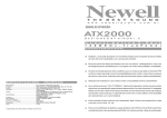
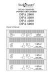
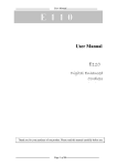
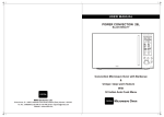
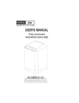
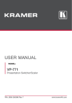
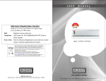
R
ARC 120A
R
1
2
3
4
5
POWER
CLIP
ARC 120A
SIGNAL
120 WATT PA AMPLIFIER
MIC/LINE
MIC/LINE
MIC/LINE
ON
MIC/LINE
AUX
BASS
TREBLE
MASTER
PA AMPLIFIER
USER MANUAL
Thank you for your purchase of the STUDIOMASTER ARC 120A Power Amplifier. This amplifier fully incorporate STUDIOMASTER’s renowned
technology and offers high reliability, rock solid stability and superb acoustic characteristics.
Features of the Product
• Five inputs : 4 balanced microphone/line inputs, One auxiliary (stereo summing) line input.
• Switchable phantom power for CH 1 mic input.
• Speaker outputs consist of 70 V, 100 V, 4 ohm, 8 ohm & 16 ohm.
• An auxiliary line output can be used for recording or connection to an external power amplifier.
• Pre-amp & Amp-in RCA connectors to use external devices such as Equalizer
• An Auto-Talk function provides voice-activated priority (VOX) for the Input 1 which overrides the remaining inputs.
• Other features include channel level, master volume controls and bass/treble controls, low cut, Level indicators, Power-On Indicator & On/off
switch .
• 24V DC Operation – Instant transfer to DC Power (car battery) if AC power fails.
2
Safety Notes
The unit is supplied with hazardous mains voltage (240V~). Leave servicing to skilled personnel only. Inexpert handling may cause an
electric shock hazard. Furthermore, any guarantee claim will expire if the unit has been opened.
Always switch of the unit before making or changing any connections.
Please observe the following terms in any case:
• The unit is suitable for indoor use only. Protect it against dripping water and splash water, high air humidity, and heat (admissible ambient
temperature range 0-40°C).
• Do not place any vessel filled with liquid on the unit, e.g. a drinking glass.
• Do not operate the unit or immediately disconnect the plug from the mains socket.
1. If there is visible damage to the unit or to the mains cable.
2. If a defect might have occurred after the unit was dropped or suffered a similar accident.
3. If malfunctions occur. In any case the unit must be repaired by skilled personnel.
• A damaged mains cable must be replaced by the manufacturer or authorized, skilled personnel only.
• Never pull the mains cable when disconnecting the mains plug from the socket, always seize the plug.
• For cleaning only use a dry, soft cloth; never use chemicals or water.
• No guarantee claims for the unit or liability for any resulting personal damage or material damage will be accepted if the unit is used for other
purposes.
• If the units is to be put out of operation definitively, take it to a local recycling plant for a disposal which is not harmful to the environment.
• The wires in the mains lead of the power supply unit are coloured in accordance with the following code:
green/yellow or green = earth
blue or black = neutral
brown or red = live
As per the colours of the wires in the mains lead of this appliance may not correspond with the coloured markings identifying the terminals in your
plug.
1. The wire which is coloured green/yellow or green must be connected to the terminal in the plug which is marked with the letter E or by the
earth symbol .
2. The wire which is coloured blue/black must be connected to the terminal which is marked with the letter N or coloured black.
3. The wire which is coloured brown/red must be connected to the terminal which is marked with the letter L or coloured red.
Warning - This appliance must be earthed.
3
Protective Circuit
The protective circuit is provided to prevent damage to the amplifier.
1. In case of a short circuit at a speaker output.
2. In case of a overheating of the amplifier.
3. In case there is DC at the output terminal.
2
Front Panel
R
1
2
3
4
5
POWER
CLIP
ARC 120A
SIGNAL
120 WATT PA AMPLIFIER
MIC/LINE
MIC/LINE
ON
MIC/LINE
MIC/LINE
1
AUX
BASS
TREBLE
MASTER
2
3
4
5
6
8
7
9
FRONT PANEL CONTROLS AND FEATURES
1) Controls for adjusting the pre-amplification for the first 4 channel INPUT 1 to INPUT 4 in Mic or Line mode.
2) Control for adjusting the pre-amplification for the AUX channel.
3) Bass - Low frequency can be cut or boosted by this control @100Hz.
4) Treble - High frequency can be cut or boosted by this control @10KHz.
5) Control MASTER VOLUME for all the Input channel.
6) CLIP LED, light up in case of overload.
7) Signal LED shows the presence of signal.
8) Power on LED.
9) POWER SWITCH:- Used for switching the unit on and off.
Rear Panel
4
24V DC
OUTPUT
LOW
CUT
240V~/50Hz
T 1.6A/250V
COM
8Ω
4Ω
PRE OUT
INPUT 5
LINE OUT
INPUT 4
INPUT 3
INPUT 2
INPUT 1
AUTO
TALK
+21V
PHANTOM
POWER
16Ω
GND
OFF
ON
COM
13
1
12
14
11
70V
AUX IN
AMP IN
MIC
LINE
MIC
LINE
MIC
LINE
MIC
LINE
OFF
ON
OFF
ON
100V
10
6
7
3
5
2
8
9
REAR PANEL CONTROLS AND FEATURES
1) Combi jack inputs for connecting microphones or line input (CH 1 to 4) with line output.
2) MIC/LINE selectable switches (CH 1-4).
3) RCA jack connectors for Auxiliary input.
4) Line Output for connecting further amplifiers. The output level is independent of Master volume control.
5) & 6) Feed-through connection PRE OUT and AMP IN for inserting a unit (e.g. equalizer); the output level of jack PRE OUT is independent of
control MASTER VOLUME.
7) Low cut switch cuts the low frequency @ 50Hz.
8) Auto talk when pressed gives vox priority to channel 1.
9) Phantom power switch when pressed gives 21V supply at the input of CH 1 Mic only.
10) Screw terminal for constant voltage line connection to the speaker.
11) Terminals for the connection to the speakers directly (Low impedance speakers).
12) Mains socket for connection to a mains (240 V~/50 Hz) via the supplied mains cable, replace a blown fuse only by same type and rating.
13) Terminals for an external 24V DC, in case if Mains power fails.
14) External earth terminal: For a possible ground connection (e.g. in case of hum problems).
3
COM
70V
100V
COM
70V
100V
LMT
LMT
LMT
LMT
LMT
LMT
Figure 1
OUTPUT
COM
4Ω
8Ω
Figure 2
OUTPUT
16Ω
Figure 3
COM
4Ω
8Ω
OUTPUT
COM
16Ω
4Ω
8Ω
16Ω
Figure 4
Figure 5
•
When 70/100V line is being used, no speakers / driver units should be connected to 4Ω or 8Ω or 16Ω (Low Impedance) Tap.
•
Loudspeaker / driver unit should be connected to either COM-100V or COM-70V terminals, but never to more than one set of terminals.
1 Applications
The amplifier has especially been designed
for use in PA systems. It can deliver 120WRMS
to 100V and 70V speakers or to a speaker
group with a total impedance of 4Ω, 8Ω or
16Ω. To the five input channels which can be
mixed with one another, microphones (CH
1 – 4) or units with line level (CH 1-3 & AUX)
can be connected. Channel 1 is equipped
with a talkover function which attenuates the
volume of the other channels by about 40 dB
in case of an announcement.
2 Setting up the Amplifier
The amplifier has been designed for
installation into a rack (482mm/19"), however,
it can also be used as a table top unit. In any
case, air must be allowed to pass through all
air vents without obstruction to ensure
sufficient cooling of the power amplifier.
2.1 Rack installation
For rack installation screw on the 2 supplied
mounting brackets to the sides of the unit. In
the rack 2 rack spaces are required for the
amplifier. To prevent top-heaviness of the
rack, the amplifier must be inserted into the
lower part of the rack. The front panel alone
will not be able to secure the unit. Side rails
or a base plate must additionally be provided.
3 Connecting the PA Amplifier
All connections should only be made by
qualified, specialized personnel and with the
amplifier switched off in any case!
3.1 Speakers
It is possible to connect PA speakers or
speakers/speaker groups with a total
impedance of at least 4 Ω. The possibilities of
connection for the speakers are shown in
figures 1 – 5. Depending on the speaker type,
use the corresponding contacts of the terminal
strip SPEAKER OUTPUT. When connecting,
observe the correct individual or total
impedance of the speakers and their correct
polarity (positive & negative connections as
shown in figs. 1 – 5). The positive connection
of the speakers is always especially coded.
3.2 Microphones
Up to four microphones may be connected to
the inputs INPUT 1 to INPUT 4.
1) When connecting a microphone, unlock
the corresponding switch MIC/LINE.
2) Phantom-powered microphones can be
used with CH 1 by switching on the 21 V
phantom power button.
3.3 Units with line output
Up to four units with a line output (e. g. CD
player, cassette recorder) can be connected
to the inputs INPUT 1 to INPUT 4 & to the
input AUX IN. When connecting to the inputs
INPUT 1 to INPUT 4, lock the corresponding
switch MIC/LINE.
3.4 Inserting an equalizer or another
unit
For external effects on the sound, an
equalizer can e. g. be inserted via the jacks
PRE OUT & AMP IN.
1) Remove the jumper between the connections PRE OUT and AMP IN. Thus, the
preamplifier & the power amplifier are
separated.
2) Connect the input of the unit to the jack
PRE OUT.
3) Connect the output of the unit to the jack
AMP IN.
Note: the amplifier does not emit a signal if
the unit inserted is not switched on, if it is
defective or not correctly connected.
Notes
1) With a voltage of 24V applied, the
amplifier will be in operation immediately &
the LED ON will light up. It will not be
possible to switch off the amplifier with the
4
POWER switch.
2) With emergency power supply, the
amplifier will deliver less power than with
mains supply.
4 Operation
1) Prior to switching on the amplifier for the
first time, set the controls INPUT 1 to 4 &
the controls AUX and MASTER VOLUME
to position “0” for the time being.
2) Switch on the amplifier with the POWER
switch. After switching-on, the LED ON
lights up. With an emergency power supply
connected, the indication LED ON lights
permanently and the amplifier is always in
operation. With the POWER switch it is only
possible to switch between mains supply &
emergency power supply in this case. For
normal operation set the POWER switch to
position “On”. In case of mains failure the
amplifier automatically switches
to emergency power supply if external
battery is connected to +24V terminal.
3) Turn up the control MASTER VOLUME)
so that the next adjustments are audible.
4) Adjust the input controls INPUT 1 to 4 and
the control AUX to the desired value.
5) Adjust the tone controls BASS & TREBLE
to optimum sound.
6) Adjust the total volume with the main
control MASTER VOLUME. The 5-step LED
row shows the output level. For an optimum
level adjust the control so that the red LED
+3 does not yet light up.
4.1 Talkover function of channel 1
Via channel INPUT 1 announcements can be
made during a musical programme. Then the
volume of the other channels is automatically
attenuated by about 40 dB. To switch on this
function, lock the button AUTOTALK.
Specifications
Outputs
Output power
120WRMS, 160WMAX
Outputs Speakers
min 4 Ω, 8 Ω, 16 Ω, 70V, 100V
Line Out
1V/600 Ω
Pre Out
1V/600 Ω
Inputs
Input 1–4
Mic 1.5 mV/1.1kΩ switchable to Line
300mV/14kΩ; XLR, balanced
Aux
300mV/50kΩ; RCA, unbalanced
Amp In
1V/14kΩ; RCA, unbalanced
Frequency range
50 –15000Hz, ±3dB
THD
1% at 120WRMS
S/N ratio
> 92dB
Low Cut
50Hz
Tone control
Bass
±10dB/100Hz
Treble
±10dB/10kHz
Operating temperature
0 – 40 °C
Power Supply
Mains voltage
240V~/50Hz
Emergency Power Supply
24V-/9A
Power consumption
265 Watts
Dimensions (W x H x D)
482 x 88 x 275 mm, 2 rack spaces
Weight
10.6kg
Notes
5
Do not attempt to make any repairs yourself. This would void your warranty.
Do not make any changes to the unit. This would also void your warranty.
The warranty is not applicable in case of accidents or damages caused by inappropriate use or disrespect of the
warnings contained in this manual. Studiomaster Professional can not be held responsible for personal injuries
caused by a disrespect of the safety recommendations and warnings. This is also applicable to all damages in
whatever form.
A1/A2, Giriraj Industrial Estate,
Mahakali Caves Road, Andheri (East),
Mumbai-400 093. India
Tel.: +91-22-42869043 / 4286 9076 Fax : 26871453
E-mail : E [email protected]
Wwww.studiomasterprofessional.com/www.audioplus-india.com
Studiomaster Professional reserves the right to make modifications to its products without notice
LITMA6P8 REV. 1
PRODUCT OF AUDIOPLUS