1
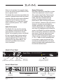
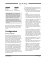
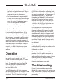
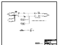
Model 80 Stereo Analog Audio Distribution Amplifier User Guide Issue 4, March 1997 This User Guide is applicable for serial numbers: Model 80 M80-00273 and later Copyright © 1997 by Studio Technologies, Inc., all rights reserved 5520 West Touhy Avenue Skokie, Illinois 60077 U.S.A. Telephone (847) 676-9177 Fax (847) 982-0747 www.studio-tech.com 50200-397, Issue 4 Table of Contents Foreword...................................................................... 5 Introduction .................................................................. 7 What This User Guide Covers ................................. 7 System Overview ..................................................... 7 System Features ...................................................... 7 Installation .................................................................... 9 Configuration ............................................................... 11 Operation ..................................................................... 12 Troubleshooting ........................................................... 12 Technical Notes ........................................................... 14 Circuit Description ....................................................... 15 Specifications............................................................... 19 Block Diagram Schematic Diagram...........................Not included in PDF Model 80 User Guide Studio Technologies, Inc. Issue 4, March 1997 Page 3 Foreword I am pleased to present the Model 80 Stereo Analog Audio Distribution Amplifier. As both president and owner of Studio Technologies, I take a very personal approach when designing products. Getting older (38 as of this writing) has increased my appreciation of the more subtle things in lifebe they a part of nature or the nuances contained in a welldesigned piece of electronic equipment. Do the technical and operational aspects of a product work together to feel right? A Studio Technologies design is ready to go only when I am completely satisfied. Many fine people worked toward making the Model 80 happen. Mitch Budniak (ace consulting engineer) designed many of the circuits. Jim Cunningham contributed to the analog design. Carrie Loving provided engineering support. Barbara Govednik coordinated the marketing communications aspects. Ben Kamen designed the automatic testing routines. Al Lux designed the printed circuit board. Jim McGuire designed the graphics. Fred Roeck performed the mechanical design. Joe Urbanczyk coordinated the safety testing and agency approvals. Additional thanks to Timothy Powell of Metro Mobile Recording, Glenview, Illinois, who provided his excellent ears when issues of sonic quality arose. His extensive field and studio experience was extremely helpful in keeping me on the audio straight and narrow. Please contact me with your questions, comments, and suggestions. I can be reached by voice at (847) 676-9177, fax at (847) 982-0747, or via the Internet @ www.studio-tech.com. Sincerely, Gordon K. Kapes President Model 80 User Guide Studio Technologies, Inc. Issue 4, March 1997 Page 5 Introduction The Model 80 Stereo Analog Audio Distribution Amplifier was developed by Studio Technologies as part of its Studio Tools group of audio support products. The Model 80 is designed to work in a large variety of applications. Specific applications include audio production, duplication, broadcast, and sound reinforcement. All Model 80 functions meet or exceed the performance of the most expensive high end audio equipment. What This User Guide Covers This User Guide is designed to assist you when installing, configuring, and using the Model 80 Stereo Analog Audio Distribution Amplifier. It also contains detailed service information, including block and schematic diagrams. System Overview The Model 80 from Studio Technologies, Inc. is the first distribution amplifier that meets the needs of the real world. The stereo input is intended to connect to virtually any line-level audio source. The ExactCal input calibration section allows for optimal audio performance over a 10 to +10dBu input level range. The eight stereo outputs meet exacting professional standards. Capable of driving balanced or unbalanced loads, each output can drive +26dBu into 600 ohms. Using front panel switches, each output can be individually configured for a nominal output level of 10 or +4dBu. The front panel controls and LEDs make installation and setup a simple job. The AC mains input power is factory configModel 80 User Guide Studio Technologies, Inc. ured for 100, 120 or 220/240V, 50/60Hz operation. Components and construction standards make the Model 80 suitable for continuous operation, even for on-air broadcast applications. System Features One Stereo Input The differential input circuitry is compatible with balanced or unbalanced signals having a nominal level range of 10 to +10dBu. Using laser trimmed components, the input offers superior commonmode signal rejection. To achieve optimal audio performance the ExactCal calibration section matches the specific input level with the Model 80s internal gain structure. Two controls and four LEDs allow fast, precise calibration. Unlike other distribution amplifiers, the Model 80 ensures that excellent audio performance can be achieved with little or no hassle. In addition to separate left and right input connectors, two input loop-through connectors are also provided. This simple feature can make installation with related equipment much easier. The loop-through connectors allow the Model 80s input source to be connected to another Model 80 or to yet another device. Eight Stereo Outputs The Model 80 contains eight independent stereo output sections. For compatibility with a range of facilities, each output section can be separately configured for 10 or +4dBu nominal output level. Each output features an electronically balanced circuit capable of driving balanced or unbalanced loads. Operating an output in an unbalanced configuration does not cause its nominal output level to change. Issue 4, March 1997 Page 7 Short circuit resistant, the rugged output circuits can drive full signal levels into 600 ohm or greater loads. The Model 80s architecture precludes the need for individual output-level trim potentiometers. With the input signal calibrated using the ExactCal section, the eight stereo outputs use 1%-tolerance components to provide precise 10 or +4dBu outputs. Audio Performance The Model 80 is the result of exacting circuit design combined with the latest state-of-the-art components. Like all Studio Technologies products, the Model 80 has survived tough listening evaluations by industry professionals. These veterans had the ears to guide us in achieving the right performance. The outcome is a product that achieves sonic excellence. Design Philosophy Most audio distribution amplifiers contain a level trim adjustment on each output. After careful study Studio Technologies concluded that these adjustments confused, and often interfered with the process of getting maximum audio performance. After checking with personnel in the field, it became clear that what is desired in virtually every distributionamplifier applications are multiple audio outputs all operating at a standard reference level. By implementing the ExactCal system, the Model 80s internal operating level can be easily calibrated to match the input signal. Once this input level matching is accomplished the eight stereo outputs can be individually configured for a 10 or +4dBu nominal operating level. In conclusion, output trim pots are not included on the Model 80 for the simple reason that better audio performance can be achieved without them! Model 80 Front Panel Input Input level Power present LED level control calibration LEDs Right input trim control 10 or +4 output level configuration switches Model 80 Back Panel AC mains connection Issue 4, March 1997 Page 8 Stereo line-level outputs Loop through output Stereo line-level input Model 80 User Guide Studio Technologies, Inc. Installation In this section you will be installing the Model 80 in an equipment rack. Audio input and output connections will be made using the Model 80s multitude of phone jacks. AC mains power will be connected to the Model 80. System Components The shipping carton contains a Model 80, User Guide, and warranty card. Units destined for North America are shipped with an AC mains cord. Your dealer or distributor will provide an AC mains cord for non-North American destinations. Mounting the Model 80 The Model 80 requires one space in a standard 19-inch (48.3cm) equipment rack. It is desirable to locate the Model 80 to allow easy access to both the front and the back panels. The back panel contains the input and output connectors. The front panel is used to access the calibration controls and output-level switches. The front panel also contains several LED indicators. The Model 80 is secured to the equipment rack using two mounting screws per side. Audio Inputs and Outputs The Model 80s audio input and output connections are made using ¼-inch 3-conductor phone jacks. The choice of phone jacks was simply a matter of real estate20 XLR connectors dont quite fit on the back of a one rack-space unit! Dont be concerned about damage to your audio quality, the jacks used in the Model 80 are manufactured by Neutrik of Switzerland and feature gold-plated contacts for excellent performance. Model 80 User Guide Studio Technologies, Inc. Balanced Connection (Input & Output) Ring () Tip ( + ) Sleeve (Shield) (Switchcraft No. 297, Neutrik NP3C, or equivalent) Unbalanced Connection (Input & Output) Tip ( + ) Sleeve (Shield) (Switchcraft No. 280, Neutrik NP2C, or equivalent) Caution: For reliable audio interconnection, the plugs you use must comply with industry standard RS-453. Switchcraft No. 297, Neutrik NP3C, or equivalent will work correctly. Refer to the Technical Notes section for details. Audio Input The Model 80 provides one stereo linelevel input. It is electronically balanced, and is compatible with balanced or unbalanced signals that have a nominal level range of 10 to +10dBu. The ExactCal section allows precise level calibration with the connected input signal. It is anticipated that in most cases a stereo signal will be connected to the input. The Model 80 can also be used as a 1-input/16-output monaural distribution amplifier, or as a dual 1-input/8-output monaural distribution amplifier. Issue 4, March 1997 Page 9 Prepare the input plugs so that tip is positive (+ or hot), ring is negative ( or cold), and sleeve is shield. The input jacks will also accept unbalanced ¼-inch 2-conductor phone plugs. With unbalanced phone plugs, tip is positive (+ or hot) and sleeve is shield. If 3-conductor phone plugs are used to connect unbalanced signals, connect positive (+ or hot) to tip and connect shield to ring and sleeve. Loop-Through The two loop-through jacks are electrically wired in parallel with the two input jacks. With this arrangement several applications are possible, such as allowing the input signals to be routed to another stereo input without the use of Y-adapters. The source signals would be connected to the input jacks. The loop-through jacks would be used to connect the source signals to the next piece of equipment using ¼-inch 3-conductor patch cords. Another application would be where more than one Model 80 is used to distribute the same input signal. Two ¼-inch 3-conductor patch cords would link the loopthrough jacks on the first Model 80 to the input jacks on the second Model 80. Yet another application would be where the Model 80 is used as a 1-input/16output monaural distribution amplifier. The monaural input would be connected to the left input jack, and a ¼-inch 3-conductor patch cord would connect the left loopthrough jack to the right input jack. Audio Outputs The Model 80 contains eight independent stereo line-level outputs which are intended for connection to a variety of analog audio devices. The outputs are Issue 4, March 1997 Page 10 electronically balanced and capable of driving balanced or unbalanced loads of 600 ohm or greater. The outputs can be individually configured for a nominal output level of 10 or +4dBu, so you can connect to all line-level inputs with no hassle. Prepare the output plugs so that tip is positive (+ or hot), ring is negative ( or cold), and sleeve is shield. The output jacks will also accept unbalanced ¼-inch 2-conductor phone plugs. With unbalanced phone plugs, tip is positive (+ or hot) and sleeve is shield. If a 3-conductor phone plug is used in an unbalanced application, connect positive (+ or hot) to tip and connect shield to ring and sleeve. AC Mains Power The Model 80 is internally configured to operate from either 100, 120, or 220/240V, 50/60Hz. In most cases, units shipped to North America are factory selected for 120V operation. Units bound for Japan are selected for 100V, while our friends down under and in Europe receive units set for 220/240V. Before connecting the Model 80 to AC mains power, check that it is configured to match the local mains voltage. Look on the back panel, adjacent to the power entry connector, for the configured voltage(s). Note that an incorrect configuration could seriously damage the unit. Should it be necessary to change the units operating voltage it must be performed only at the factory or by an authorized service technician. The Model 80 uses an IEC standard connector to mate with the AC mains cord. The wire colors in the AC mains cord should conform to the internationally recognized CEE color code and must be wired accordingly: Model 80 User Guide Studio Technologies, Inc. Connection Wire Color Neutral (N) Line (L) Protective Earth (E) Light Blue Brown Green/Yellow Safety Warning: The Model 80 does not contain an AC mains disconnect switch. As such the mains cord plug serves as the disconnection device. Safety consideration requires that the plug and associated outlet be easily accessible to allow rapid disconnection of mains power should it prove necessary. As soon as mains power is connected, the Model 80s power present LED will light. The unit is now ready for years of trusty service! Configuration Input Level Calibration With the ExactCal calibration section its simple to match the nominal level of the input signal with the Model 80s internal circuitry. Two controls, level and right trim, along with four LEDs are the ExactCal operator controls. The level control is a stereo device, adjusting the input sensitivity for both the left and right inputs. The right trim control allows the input sensitivity for the right channel to be adjusted over a 3dB range. This allows compensation to be made for small differences in the left and right input levels. Two LEDs, labeled Lo and Hi, are associated with each input. They are provided as an aid to calibration, as well as serving as signal present indicators. Model 80 User Guide Studio Technologies, Inc. The following is a step-by-step procedure for using the ExactCal section to match an input signal with the Model 80: Set the level control fully counterclockwise (all the way to the left end of the travel). Supply a 1kHz sine wave to both the left and right line inputs. Set the level of the source to be precisely the nominal operating level. If, for example, the output of a console is connected to the input of the Model 80, the console output should be adjusted so that the meters read 0dB or 100%. If the output of the console is a +4-type, then setting the consoles left and right output levels to nominal should find the console output levels to be exactly +4dBu. Slowly turn the level control clockwise. As you increase the level, watch the LEDs associated with the left channel. The LED labeled Lo will light first, then both LEDs will light, then only the LED labeled Hi will light. The correct setting is where both LEDs light. Careful adjustment is required as the window where both LEDs light is somewhat less than 1dB. Observe the LEDs associated with the right channel. If they are both lit no adjustment of the right trim control is required. If only one is lit adjust the right trim control, using a small flat blade screwdriver, so that both LEDs light. (We like the Xcelite R3324 screwdriverit has the clear green handle and is commonly used to calibrate audio equipment.) Issue 4, March 1997 Page 11 For practice, mess up the settings of the level and right trim controls. Again follow the calibration procedure and again get things set up correctly. For future reference it may be helpful to mark the correct input level and right trim adjustment points. Use a grease pencil or a piece of adhesive tape so as not to damage the front panel. Disconnect the 1kHz signal and connect the normal audio source. Output Level Selection Each of the eight stereo line-level outputs is individually configurable for a 10 or +4dBu nominal output level. Eight DIPtype switches, located on the right side of the front panel, are used to set the output levels. The legend on the switches correspond to the output channel numbers. A switch that is set to the up position sets its associated output channel for 10dBu. A switch set to the down position sets the output for +4dBu. A small screw driver may be of assistance when setting the switches. Operation Now that youve installed and configured the system, youre ready to go. You should find operation very easy, as there is almost nothing to do on a day-to-day basis. For peace of mind, the ExactCal LEDs will give you a visual indication whenever audio signals are present on the Model 80s input. The LED labeled Lo will light whenever the input signal is within the range of 18dB below and 0.5dB above the nominal operating level. The LED labeled Hi will light Issue 4, March 1997 Page 12 any time the input signal is greater than 0.5dB below the nominal operating level. This sounds a bit confusing but isnt really so hard to understand. As an example, if you have a nominal +4 signal connected to the Model 80s line input and the ExactCal section has been used to calibrate the input, the Lo LED will light when the signal is between 14 and +4.5dBu, the Hi LED will light when the signal exceeds 3.5dBu. In most cases the input level control shouldnt be changed, as it will change the input calibration. In special applications you may want to use it as a fader, simultaneously adjusting the level on all eight stereo outputs. In the fully counterclockwise position the eight outputs are completely off. Before you use the level control as a fader ensure that you mark the position of the knob where the input is calibrated. If you change the input source you can use the ExactCal section to recalibrate the input. Refer to the configuration section of this guide for details. Each of the eight outputs are fully independent. You can patch, reconnect, or even short out an interconnecting cable without effecting the other outputs. Using the front-panel DIP switches you can change the output level of any or all of the outputs whenever you wish. Troubleshooting If youre having problems getting the Model 80 up and running, this section can help. If you havent read the other sections of this guide, you should do so before proceeding. Model 80 User Guide Studio Technologies, Inc. If the Model 80 Doesnt Work At All A source of AC mains power must be connected to the Model 80. Depending on the version you have purchased, 100, 120, or 220-240Vac, 50/60Hz is required. Confirm what mains voltage is required by observing the selection boxes to the left of the AC mains connector on the back panel. Whenever mains power is connected the front panel power present LED should light. If the LED is not lit confirm that the main power source is active (hot) and that the connector on the cord is securely mated with the plug on the back panel. For safety in the event of a major internal failure or the connection of incorrect AC mains voltage, the Model 80 contains a fuse inside the cabinet. The fuse will open (blow) if the failure of an internal component causes excessive current to be drawn from the internal power supply. The fuse will also open should 220-240Vac be connected to a Model 80 that is configured for 100 or 120Vac operation. The fuse is intended to be replaced only by a qualified service technician. This person will have the training to safely access the guts of the Model 80 and identify where a problem is located. Incorrect Output Levels You must correctly set the input level and right trim controls for the eight stereo outputs to receive a precise 10 or +4dBu nominal output level. These controls match the level of the audio input signal with the Model 80s internal circuitry. Refer to the Configuration section of this guide for detailed instructions. Intermittent Audio Connections Should you experience audio connections Model 80 User Guide Studio Technologies, Inc. that seem to be flaky or intermittent, refer to the Technical Notes section of this guide. The ¼-inch 3-conductor phone jacks used on the Model 80 are of very high quality, conforming to the industry standard EIA RS-453. Some plugs do not meet this standard, specifically in the shape of the tip conductor. In rare cases you may have to replace plugs on interconnecting cables to remedy an interconnection problem. Switchcraft No. 297 or Neutrik NP3C phone plugs will function correctly. Headphones as a Troubleshooting Tool One of the simplest means of checking for the overall presence of a line-level audio signal is to listen to the signal using a pair of stereo headphones. The signal level and source impedance of contemporary audio output circuitry can easily drive headphones to quite a high sound pressure level. Carefully used, headphones are a great means of rapidly determining if signal is present on an audio line. Note that in a few cases the plugs used by headphone manufacturers do not comply with the EIA-453 specifications for ¼-inch plugs. You may want to designate a pair of headphones for linelevel testing and attach a plug of known quality. We have found that even some very high quality headphones have nonstandard plugs; be warned! Warning: Safety First! Do not plug a pair of headphones into a jack on the Model 80 while the headphone ear pieces are against your ears. High sound pressure levels may be present. Only after a signal is connected should you slowly put the headphone transducers near your ears! Issue 4, March 1997 Page 13 To confirm that a signal is present on the input of the Model 80 you can plug the headphones into the loop-through connectors associated with the left and right channels. After ensuring that the level will not hurt your ears, you can listen for the presence of audio and get an idea of the general quality of the source. With a balanced input signal you should hear the input in both the left and right earpieces of the headphones. With an unbalanced source you would, in most cases, hear signal in only the left channel of the phones. To confirm that signals are present on the eight stereo outputs you can plug the headphones into the left and right output jacks. Outputs configured for +4dBu operation will be significantly louder in the headphones. Since all Model 80 outputs are balanced, you should observe signal in both the left and right earpieces. Rapidly walking through the 16 output jacks will confirm the proper operation of the Model 80. Technical Notes ¼-Inch Plugs versus EIA RS-453 An incompatibility problem lurks between some ¼-inch phone plugs and the jacks found on professional audio equipment. While all the plugs seem to look the same, some do not comply with the industry standard, called EIA RS-453. This standard defines the physical dimensions, including the shape of the plugs tip. It seems that some plug manufacturers dont bother to make the tip comply with the standard. Why is this relevant to you? Because the phone jacks used on the Model 80 do comply with the standard. Issue 4, March 1997 Page 14 They expect to be mated with plugs that also meet the specification. When interfacing with the Model 80 be careful with the plugs you utilize. Should a connection appear flaky, sound noisy, or make an intermittent contact, the most likely problem is a nonstandard phone plug. Replace the plug if this is the case. You should find that all plugs from Switchcraft or Neutrik will work correctly, specifically Switchcraft No. 297 or Neutrik NP3C. Definition of LeveldBu Whenever possible, Studio Technologies has opted to use the dBu designation as it seems to be quite rational. Using dBm was fine when all audio line outputs were terminated with 600 ohm loads. In this way it was easy to say that 0dBm is 1 milliwatt dissipated in the known load (i.e., 0dBm across 600 ohms will measure 0.7747V). In contemporary situations an output is rarely terminated with 600 ohms; generally 10k ohms or higher. The dBu designation is better because it refers to dB referenced to 0.7747V, with no reference to load impedance. This takes into account todays audio scene where signals have a low source impedance, and a high input impedance. The dBu designation is becoming the standard for the professional audio industry. 10 Output Level Reference To those of you who are technical nitpickers we feel than an explanation is in order. Operational simplicity, rather than historical convention, led Studio Technologies to make the 10 outputs referenced to dBu rather than to dBV. We are well aware that in the past a 10 output was often referenced to 1 volt, not to 0.7747. When the Model 80 was first designed it was assumed that the +4 Model 80 User Guide Studio Technologies, Inc. output would be in dBu and the 10 output would be in dBV. We soon realized that this would cause cranium problems for many users. A user monitoring one of the Model 80s outputs would expect to see a 14dB drop on their VU meter when going from the +4 to the 10 DIP switch position on the Model 80s front panel. They actually would be switching from a +4dBu output to a 10dBV output, a difference of 11.78dB; confusion would immediately reign! To avoid this situation we took the liberty of keeping the 10 referenced to dBu. This should in no way effect the ability of the Model 80 to interface with other equipment, while making life easier for everyone. Circuit Description This information will help you understand how the Model 80 functions and, if required, help you identify where a failure may be located. Please refer to the attached block and schematic diagrams while reading this material. Schematic Nomenclature The schematics show the graphical representation of all the electronic components, along with their electrical value and connections. Traditionally, a problem with schematics has been the decimal point marking. It either disappears due to bad printing, or dust, dirt or other imperfections end up looking like decimal points. For clarity, Studio Technologies has adopted a more European component marking scheme. Upon first review it may seem quite confusing, but it can eliminate problems. For resistors, the designation K for kilo (1000) has been moved to the decimal point position. A 4700 ohm resisModel 80 User Guide Studio Technologies, Inc. tor is shown as 4K7, rather than 4.7K. An example for a one percent value, a 49900 ohm resistor would be shown as 49K9. For capacitors, the letter r is simply substituted for the decimal point marking. A 0.47uf capacitor is shown as r47uf. Once you are accustomed to this system you may well prefer it. Power Supply The Model 80 contains one linear power supply circuit that generates filtered and regulated ±15Vdc. The circuit uses a step down transformer, with the primary side containing two 115V windings. This allows it to be configured for nominal AC mains voltages of 100V, 120V, or 220/240V. For 100V and 120V operation the primaries are connected in parallel; for 220/240V operation they are connected in series. The configuration is performed using jumper straps on the circuit board. For safety, a fuse is in series with the incoming AC mains power. Because the Model 80 is intended for continuous operation, an AC mains power switch is not included. This serves several purposes: eliminating the chance of a power switch being accidently turned off, increasing the physical isolation between the nasty 50/60Hz fields and the sensitive analog circuitry, and eliminating the physical space required by a switch. The step down transformer has dual 17V secondaries for 120V and 220/240V operation, and dual 20V secondaries for 100V operation. The secondaries are connected in series, with the series connection point providing circuit common, as well as being strapped to the metal chassis and the ground pin of the power entry connector. The transformers secondary is fed to a full wave diode bridge. Issue 4, March 1997 Page 15 The output of the bridge is filtered with electrolytic capacitors, producing unregulated ±20Vdc. Two integrated circuit regulators produce the ±15Vdc from the unregulated voltages. Capacitors on the outputs of the regulators provide stability. The ±15Vdc is used by the analog circuitry. The +15Vdc is also used by the meter circuits. The 15Vdc is also used by the power present LED. Interesting technical note department: notice that a diode is connected from the output pin of each regulator to circuit common. These serve to keep the ±15Vdc rails at, worst case, one diode drop (0.7V) away from ground in the opposite polarity. This is important when supplying bipolar loads, such as operational amplifiers, etc. Without these diodes the regulators can latch-up when mains power is applied or removed. When mains power is initially applied one of the supplies can come up (get to its operating voltage) sooner than the other. This voltage is fed back through the loads (the op-amps) to the output pin of the other regulator that is still coming up to full voltage. Upon seeing this unexpected opposite polarity voltage on its output pin, the regulator may get very unhappy, possibly latching into a nonoperating state, drawing lots of current, burning up, etcetera! The protection diodes keep this condition from happening. For service assistance, several test points are included on the printed circuit board: ±20V unregulated, ±15Vdc and circuit common. Analog Circuitry The Model 80 takes advantage of an excellent series of audio-specific inteIssue 4, March 1997 Page 16 grated circuits from Analog Devices. Using these parts saved us from using literally dozens of additional components. More importantly, performance levels were achieved that would have been difficult, if not impossible, to obtain with more conventional circuitry. These Analog Devices parts have the common prefix of SSM, indicating their roots in a company called Solid State Microelectronics for Music, purchased, by way of Precision Monolithics, a few years ago. Hats off to the guys and gals at Analog Devices! Audio Input The Model 80 contains one stereo linelevel input circuit. The input is compatible with balanced or unbalanced signals having a nominal level range of 10 to +10dBu, with relative differences in signal level of up to 3dB. The function of the input circuitry is to receive the left and right audio signals, separate out commonmode hum and noise, unbalance the signals, and process them such that both the left and right signals are presented to the Model 80s internal audio buses at precisely 2dBu. Left and right line-level audio enters the Model 80 by way of two ¼-inch 3-conductor phone jacks. The loopthrough feature is implemented by simply connecting the left input/left loop-through and right input/right loop-through jacks electrically in parallel. From the input jacks the audio is also directly coupled into two SSM-2143 differential (balanced) line receiver integrated circuits. The 2143s have excellent common mode rejection, low noise, and high slew rate. Intended for professional audio applications, they contain two 12k ohm input resistors, individually laser trimmed for accuracy. By Model 80 User Guide Studio Technologies, Inc. design, the 2143 provides 6dB (voltage) of attenuation. The output of each SSM-2143 is capacitive coupled into one section of a dual (stereo) log taper potentiometer (pot). This pot is the input level control that is accessible from the front panel. The pot adjusts the input sensitivity for both the left and right inputs. Note that the coupling capacitors used to couple the 2143s to the pot are a nonpolar type, allowing for small DC voltages of unknown polarity to be received on the inputs. The wiper of each section of pot is connected to the noninverting input of a section of low-noise operational amplifier. The voltage gain of the left channel op-amp is fixed at approximately 15dB. The combination of a fixed resistor and trim potentiometer allows the voltage gain of the right channel op-amp to be adjustable over a nominal range of 13 to 17dB. This implements the right trim function accessible from the front panel, allowing differences in the left and right signal levels to be accounted for. The output of the left channel op-amp section is defined as the left channel internal audio bus. Its nominal level is 2dBu. The same holds true for the right channel op-amp, where its output is the right channel internal audio bus. Metering Outside of the overall system architecture, the metering section of the Model 80 is probably the most unique. Two identical meter circuits monitor the audio level on the left and right internal audio buses. Audio signal enters each meter circuit via an operational amplifier configured as a half-wave synchronous rectifier. The resulting DC output is smoothed via a resistor/ capacitor low pass filter. The output of the Model 80 User Guide Studio Technologies, Inc. low pass filter is connected to inputs on three sections of integrated circuit comparator. Four precision resistors are connected in series with the +15Vdc power supply rail to create three DC voltages. These act as reference voltages and are used as the switching points for the comparators. The outputs of two of the comparator sections are connected as an OR gate and control the Lo LED. The third comparator section controls the Hi LED. Notice that the comparators are connected such that the LEDs light simultaneously only over a very small voltage range. This is the calibration window that the user observes. The current through the LEDs is directly controlled by transistors, whose bases are driven by pull-up resistors on the outputs of the comparators. ExactCal One of the highlights (or should we say hype-lights!) of the Model 80 is the ExactCal section. To a user the ExactCal controls and LEDs allow a wide range of input signals to be precisely interfaced with the Model 80. ExactCal is a term that Studio Technologies selected to describe the combination of the audio input and metering circuitry. The audio input circuitry allows a user to adjust the input sensitivity to match the level of the audio source. The metering circuitry provides the user with visual feedback, allowing the controls to be set to the correct position. Audio Outputs Eight identical circuits provide the eight stereo line-level outputs. Each of the eight circuits is essentially two identical circuits that share a common nominal output level control lead. For simplicity, only the left channel of a stereo output circuit will be described. Issue 4, March 1997 Page 17 The left channel internal audio bus is connected, by way of a resistor, to the inverting input of an operational amplifier. The operational amplifier is configured as an inverting, adjustable gain circuit. One section of high performance analog switch controls the gain of the op-amp by shunting a resistor in the feedback loop. When the analog switch is in the off (open) state the op-amp is operating at essentially unity gain. When the analog switch is in the on (closed) state the gain is less than unity, providing an attenuation of 14dB (voltage). The state of the analog switch is controlled by one section of DIP switch. The DIP switch, which produces a 0 or +15Vdc logic signal, is accessible to the user by way of the front panel. The output of the op-amp is capacitor coupled to the input of an SSM-2142 differential (balanced) line driver integrated circuits. The 2142 provides an electronically balanced, low-impedance output and is capable of driving high signal levels into 600 ohms or greater. Because of the nature of a differential driver, an effective 6dB boost in signal level is achieved. The outputs of the 2142 are directly connected to the output jack. The nominal output level is controlled by our friend the analog switch. When the switch is in the off (open) state a signal at nominal 2dBu is presented to the line driver. With the intrinsic 6dB of gain the nominal level at the output jack is +4dBu. When the analog switch is in the on (closed) state a signal at nominal 16dBu is presented to the line driver. This results in a 10dBu signal at the output jack. Issue 4, March 1997 Page 18 Model 80 User Guide Studio Technologies, Inc. Specifications Audio Outputs Qty: 8, stereo (separate left and right output connectors) Model 80 Stereo Analog Audio Distribution Amplifier Type: electronically balanced, direct coupled, intended to drive loads of 600 ohms or greater, can be connected balanced or unbalanced Mounting One space in a standard 19-inch (48.3cm) rack AC Mains Requirement 100, 120, or 220/240V, ±10%, factory configured, 50/60Hz, 100-120V 0.4A maximum, 220/240V 0.2A maximum Fusing Qty: 1 Nominal Output Level: 10dBu (245mV) or +4dBu (1.228V), each output individually switch configurable Maximum Output LevelBalanced: +27dBu into 10k ohms, +26dBu into 600 ohms, Unbalanced: +21dBu into 10k ohms, +20dBu into 600 ohms Output Impedance: 50 ohms Type: 5 x 20mm time lag (Littelfuse 218-series or equivalent) Frequency Response: 10Hz-70kHz +0/0.5dB (down 1dB @ 110kHz) Rating: 0.400A for 100 and 120V mains power, 0.200A for 220/240V mains power Distortion (THD+N): 0.004% (measured at +4dBu input, +4dBu output, 20Hz-20kHz) Connectors Audio: dual, ¼-inch, 3-conductor phone jacks, gold-plated contacts. (Manufactured by Neutrik.) Mates with all plugs specified by EIA RS-453. S/N Ratio: 91dB (20Hz-20kHz, ref. +4dBu) AC Mains: standard 3-blade plug, meets IEC 320 specifications Audio Input Qty: 1, stereo (separate left and right input connectors) Loop Through: hardwired in parallel with input (separate left and right loop-through connectors) Type: electronically balanced, direct coupled Input Compatibility: can be connected to balanced or unbalanced signals Crosstalk: 75dB (1kHz, ref. +4dBu) LED Indicators Qty: 5 Function: 1 power present, 4 input level calibration Dimensions (Overall) 19.00 inches wide (48.3cm) 1.72 inches high (4.4cm) 6.65 inches deep (16.9cm) (1 standard rack space) Weight 7.0 pounds (3.2kg) Impedance: 24k ohms Nominal Input Level: 10 to +10dBu Input Level Control: allows calibration over 10 to +10dBu input range Right Trim Control: allows adjustment of right input level over a 3dB range, nominal Specifications and information contained in this User Guide subject to change without notice. Maximum Input Level: +27 dBu balanced, +21 dBu unbalanced Common Mode Rejection: 90dB @ DC and 60Hz, 85dB @ 20kHz, 60dB @ 400kHz (typical) Model 80 User Guide Studio Technologies, Inc. Issue 4, March 1997 Page 19