1
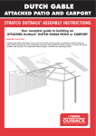
DUTCH GABLE
FREESTANDING CARPORT
STRATCO OUTBACK®ASSEMBLY INSTRUCTIONS.
Your complete guide to building a
FREESTANDING Outback DUTCH GABLE CARPORT
BEFORE YOU START
Carefully read these instructions. If you do not have all the necessary tools or information,
contact Stratco for advice. Before starting lay out all components and check them against the
delivery docket. The parts description identifies each key part, and the component location
diagram indicates their fastening position.
PARTS DESCRIPTION
RIDGE KNUCKLE
Slots inside the gable rafters to
form connection at the ridge
PURLINS
Purlins provide support for
cladding
FOOTING PLATE
Slots inside column
to form on concrete
footing connection.
EAVES KNUCKLE
Slots inside gable rafter and
column to form connection at
eaves.
FOOTING
KNUCKLE
Slots inside
column to form
an in ground
footing
connection
COLUMNS AND
RAFTERS
Pre cut 120 outback
beam make up
rafters and columns
HIP PLATE
Connects purlins to
the hip rafter.
RIDGE CAP
This flashing covers the roof
sheets at the gable ridge.
BARGE CAP
The barge cap covers
the area where the
deck finishes at portal
frame
INFILL PANELS
Sufficient number of sheets are
provided, from which the required
dutch gable infill panels can be
cut.
HIP FLASHING
Covers the roof sheet ends
along the hip rafter.
WEATHER STRIP
Weather strip supports infill
panel and covers the sheet
ends at the collar tie
HEX HEAD SELF DRILLING
SCREWS
Screw types vary depending upon
the connection, ensure correct
screws are used
10 x 16
12 x 20
PANEL STRIPS
Panel strips attach to the
infill panel where applicable
BOLTS AND RIVETS
Bolt types vary depending
upon the connection, ensure
the correct fixings are used
68 mm PURLIN
BRACKET
This bracket
fastens end
purlin supports
in place and
front purlins to
end purlin
supports
14 x 95
UTBA
V ERANDAHS
PATIOS
CARPORTS PERGOLAS
K
®
COMPONENT LAYOUT
9
15
1
20
18
13
4
19
11
12
7
21
6
10
8
5
2
3
16
17
14
Figure 1
Hip Flashing
7
Hip Plate Connection
13
Ridge Connection
18 Infill Panel
2
End Frame
8
Seated Connection
14
Footing Connection
19
3
Portal Frame
1
4
5
6
Weather Strip
9
Ridge Knuckle
15
Barge Cap
20 Panel Strips
Purlins
10
Eaves Knuckle
16
Footing Plate
21 End Purlin Support
Eaves Purlin Connection
11
Roof Cladding
120 Beam-Beam Connection
12 Collar Tie
OR
17
Footing Knuckle
OVERALL LENGTH
DUTCH GABLE PLAN VIEW
OUTSIDE OF COLUMNS
IP
H
R
E
T
F
A
R
END
FRAME
45°
OVERALL LENGTH
OUTSIDE OF COLUMNS
A
F
COLLAR TIE
OVERALL WIDTH
R
OUTSIDE OF COLUMNS
E
OVERALL WIDTH
T
END
FRAME
INTERNAL
PORTAL
FRAME
COLLAR TIE
R
INTERNAL
PORTAL
FRAME
FRONT PURLIN
IP
END FRAME
SPACING
INTERNAL
PORTAL
FRAME
OUTSIDE OF COLUMNS
H
45°
END
PURLIN
SUPPORT
FRAME CENTRES
SINGLE CARPORT
END FRAME
SPACING
FRAME CENTRES
DOUBLE CARPORT
2
CONSTRUCTION
MARKING OUT CARPORT POSITION
OUTSIDE OF COLUMNS
A) IN GROUND FOOTING
END FRAME
SPACING
FRAME SPACING
OUTSIDE OF COLUMNS
END FRAME
SPACING
Place stakes at the carport column locations using the
appropriate dimensions from the drawings supplied.
Note: These column locations are very critical, as the
roof sheet lengths are governed by these
dimensions.
4
Therefore ensure the end frame spacing and the width of
the carport are exactly as specified in the drawings.
FRAME SPACING
FRAME SPACING
STRING LINE
LS
NA
O
IAG
D
HOLE POSITIONS
END FRAME
SPACING
OUTSIDE OF COLUMNS
END FRAME
SPACING
The end frame spacing, gives the centreline spacing
between the rectangular end portal frame and the internal
gable portal frame. Where more than two internal portal
frames are required, space at the frame spacing
dimensions specified on the drawings supplied.
Place the footing plate in the appropriate locations as
specified on the drawings supplied. The orientation of the
base plate is such that the smaller dimension runs along the
width as shown in Figure 4.
Mark the position of the holes through the existing holes in
the footing plate. Remove the footing plate and drill into
concrete using the values given in Table 1.
OUTSIDE OF COLUMNS
3
Tie string lines between the stakes to ensure the footings
are in line. Check the dimensions and diagonals for
squareness.
The end frame spacing, gives the centreline spacing
between the rectangular end portal frame and the internal
gable portal frame. Where more than two internal portal
frames are required, space at the dimensions specified on
the drawings supplied.
Dig holes to the required size as stipulated by your Council
Application Form. Place bricks in the bottom of the holes to
give a solid base onto which the footing knuckles can be
positioned.
NOTE: Do not drill completely through slab, as
chemical anchors require a solid base to bear
against.
Use chemical anchors (for size refer to Table 1) together
with the appropriate anchor capsules and install according
to the manufacturers recommendations.
Leave the Stud Bolt undisturbed for the minimum time
specified by the manufacturer for the resin to cure. Curing
times are dependent on the concrete temperature at the
time of installation.
Note: Footing plates are not fixed until portal frames have
been assembled.
CARPORT
CHEMICAL ANCHOR
SIZE (mm)
HOLE DIAMETER
(mm)
HOLE DEPTH
(mm)
B) ON CONCRETE FOOTING
CARPORTS < 5000mm WIDE
IN W41 WIND SPEED
M10x130
12
95
If bolting columns onto existing concrete slab check to
ensure concrete dimensions are as specified by your
Council. Stratco does not take any responsibility for
concrete failure.
CARPORTS ³ 5000mm WIDE
IN W41 WIND SPEED
M12x160
14
115
Mark the position of the columns as shown in Figure 4.
using the appropriate dimensions from the drawings
supplied.
Note: These column locations are very critical, as the
roof sheet lengths are governed by these dimensions.
Therefore ensure the end frame spacing and the width of
the carport are exactly as specified in the drawings
supplied.
TABLE 1
ASSEMBLE PORTAL FRAMES
Place the three knuckle connections inside portal frame
members, using a hammer to tap in position (a block of
timber should be used whenever hammering to avoid
damaging paintwork).
Important note: Knuckles are colour coded as follows,
ensure that the correct knuckle is used for each connection.
22° Ridge Knuckle - Green
22° Eaves Knuckle - Red
30° Eaves and Ridge Knuckle - Yellow
Join all frame members; first insert eaves knuckle into
column to rafter joint, next the footing knuckle/base plate
into the column base, and then finally the ridge knuckle into
the two halves of the frame at the ridge (refer to figure 5 for
knuckle locations).
RIDGE
CONNECTION
2 (12 X 20 HEX HEAD SELF
DRILLING SCREWS) THROUGH
TOP OF BOTH RAFTERS
RAFTER
RAFTER
Use a hammer at the eaves knuckle to join the two sides
together as shown in Figure 5. If knuckles are difficult to
insert apply a lubricant or grease.
RAFTER/RAFTER JOINT
(RIDGE CONNECTION)
2 (12 X 20 HEX HEAD SELF
DRILLING SCREWS) EACH SIDE
OF BOTH RAFTERS
HAMMER
EAVES
CONNECTION
COLUMN/RAFTER JOINT
(EAVES CONNECTION)
6
2 (12 X 20 HEX HEAD
SELF DRILLING SCREWS) THROUGH
TOP OF EAVES PURLIN CONNECTION
AND RAFTER
EAVES PURLIN
CONNECTION
BRACKET
BLOCK OF
WOOD
COLUMN BASE
(FOOTING CONNECTION)
5
EAVES AND RIDGE CONNECTION
Screw together eaves and ridge connections, using two 12
x 20 hex head self drilling screws both sides of each
member and two 12 x 20 hex head self drilling screws
through the top (double flange side) of each member. Pilot
holes indicate screw locations as shown in figures 6 and 7.
Make sure that the two ends are flush at the connection,
leaving no gaps.
Important Note: An eaves purlin connection bracket is
attached as part of the eaves connection to both sides of the
portal frame using two 12 x 20 hex head self drilling screws
as detailed in figure 7 (pre drill for ease of fastening).
RAFTER
2 (12 X 20 HEX HEAD SELF
DRILLING SCREWS) BOTH
SIDES OF RAFTER AND
COLUMN
COLUMN
7
FOOTING
CONNECTION
COLUMN
2 (M10 CUP HEAD
BOLTS) THROUGH
PRE DRILLED HOLES
COLUMN SHOULD
NOT COME INTO CONTACT
WITH CONCRETE OR SOIL
FOOTING CONNECTION
For all footing connections, bolt together through pre drilled
holes using M10 cup head bolts as shown in figure 8.
Ensure that the bolt heads are all on the same side of the
frame.
Mark the purlin centres on the top of the portal frames.
2 (12 X 20 HEX
HEAD SELF DRILLING
SCREWS) THROUGH
OUTSIDE OF COLUMN
8
ASSEMBLE END FRAMES
Pre-drill a 10 mm diameter hole 34 mm down from the top of
the column through the centre of the double flange side
(eaves purlin will bolt onto here) as shown in Figure 9.
Attach end wall beam-column connection 30 mm down
from the top inside face of column, using two 10 x 16 hex
head self drilling screws.
Note: Double flange must always be on the outside of the
frame.
Slip end rafter over connection and fasten with four
coloured 10 x 16 hex head self drilling screws as in Figure
9.
30 mm
END FRAME
34 mm
CLAMP
10 mm DIA
HOLE
END FRAME RAFTER
FINISH CONCRETE
SLIGHTLY RAISED
TOWARDS COLUMN
DOUBLE
FLANGE
BRACES
FASTEN WITH 2 (10x16 HEX
HEAD SELF DRILLING SCREWS
ON EACH SIDE
END FRAME
COLUMN
9
BRICK
PRE-DRILL PURLINS
Note: All purlins are supplied to suit the individual Heritage
designs, It is important you refer to your plan and check
purlin lengths before cutting.
For extra long carports where you need to join two purlins,
make sure they are joined over a portal frame and that the
top lap faces the same way for both purlins to achieve a
neat joint.
Cut the eaves purlins to correct length. Pre-drill the eaves
purlins with 10 mm diameter holes at the end portal frame
locations. Only drill holes through the single side rib of the
eaves purlin (see Figure 10).
CUT AS SPECIFIED ON PLAN
34
10 mm
DIAMETER
HOLE
34
DRILL THROUGH
SIDE RIB
14 x 95 SCREW
DRILL THROUGH
DOUBLE FLANGE
34
ROOF PURLIN
CUT AS SPECIFIED ON PLAN
INTERNAL PORTAL
RAFTER
11
ENSURE THE TOP
OF THE EAVES PURLIN
IS LEVEL WITH THE TOP
OF THE END FRAME
1.0 x 3/8
HEX HEAD
BOLT
END FRAME RAFTER
EAVES PURLIN
END FRAME
END FRAME
COLUMN
12
Check column base is at the ground surface, and the clear
opening between columns is correct. Finally and most
importantly check that the columns are vertical.
EAVES PURLIN
34
FOOTING
KNUCKLE
10
Concrete the footings and leave overnight to cure.
Note: The concrete should be finished slightly raised
towards the column, ensuring water runs away from the
column, see Figure 11.
Important Note: If concrete or soil is in permanent contact
with the colorbond columns, corrosion will result in the base
of the coloured column. Refer to the "Selection, Use and
Maintenance of Stratco Steel Products" brochure for
complete details of maintenance requirements.
ERECT END FRAMES
B) ON CONCRETE FOOTING
A) IN GROUND FOOTING
Select the end rectangular portal frames. Place the footing
plates in position and bolt securely.
Stand the end portal frame in the appropriate footing
location and temporarily brace in position with clamps and
struts (see Figure 11).
Bolt the eaves purlins to the sides of the end frame columns
using the 1.0 x 3/8 hex bolts provided, so that the purlins
are level with the top of the column as shown in Figure 12.
Raise the other end frame and secure to eaves purlins.
Ensure the ends of the purlins are flush with the outside
faces of the end frames and the diagonal distances
between the end frames are equal.
ERECT PORTAL FRAMES
Now stand the internal portal frames in position, so that the
eaves purlins rest on the eaves connection brackets
Fasten the eaves purlin to the eaves connection through
the underside of the bracket using two coloured 10 x 16 hex
head self drilling screws (see Figure 18).
Note: The drawings supplied define the positioning of the
internal portal frames relative to the end frames and as
mentioned these are very critical.
CHECK FRAMES
Now that the portal frames are in place, check the
dimensions between portals are correct, and all portals are
in line and vertical. Most importantly check the diagonal
measurements are equal.
SEATED HIP
CONNECTION
IN CORNER
COLLAR TIE
14X95 SCREW
14X95
FRON
ROOF STRUCTURE
Refer to Figure 2
T PUR
LIN
C.L.
C.L.
HIP RAFTER CONNECTION PLATE
FIX WITH 10X16 SCREWS
EAVES PURLIN
110
P1
P2
C.L.
RIDGE
END WALL
RAFTER
END WALL
COLUMN
P1 = END SPAN
Attach remaining roof purlins as shown in Figure 13.
Note: Only 3 purlins for single carport, one purlin at eaves,
one at ridge and one intermediate. Quantities may vary
depending on roof cover and carport width.
C.L. = CENTRELINE
P1
C.L.
110
C.L.
14
Single Size Carport
P2 = INTERNAL SPAN
P1
HIP
RAFTER
WS
END PURLIN SUPPORTS
(IF REQUIRED)
Pre-drill the roof purlins with 14 x 95 hex head self drilling
screws at the internal portal locations, through the double
flange first. Fasten one of these roof purlins at the ridge as
shown in Figure 13. Check roof diagonals to ensure sloping
roof area is square.
P1
SCRE
RIDGE
Double Size Carport
Fasten the remaining roof purlins at the ridge location and
900 mm further down the rafter on each side. Position a
purlin (first roof purlin - see Figure 15) 900 mm up the rafter
from the eaves purlin (double flange on top).
P1 = END SPAN
C.L. = CENTRELINE
13
Screw the four seated hip rafter connections to the top
inside corners of the structure, level with the top of the
eaves purlin. Fix with two 10 x 16 hex head self drilling
screws, see Figure 14.
Lift hip rafter onto seated connection ensuring double
thickness flange is at the top. The hip rafter angles away
from the rectangular end frame at 45° and is screwed
onto the internal gable frame as shown in figure 14.
Note:This 45° angle is critical in ensuring correct
shape of the Dutch Gable and therefore the sheet
lengths.
Cut hip rafters to length and pre-drill with one large 14 x
95 hex head self drilling screw at the end, ensuring
double thickness flange is at the top. Position hip rafter
on the seated hip connection and fasten underside with
two coloured 10 x 16 hex head self drilling screws.
Screw the remaining end onto the top of the internal
portal frame. Do not over tighten, preventing crushing of
the hip rafter.
Measure and cut a 45° mitre at the ends to fit flush against
the hip rafter. Pre-drill with 14 x 95 self drilling screw at the
internal rafter locations and fasten in place.
Fix hip rafter connection plate to the underside of the hip
rafter/side purlin joint using 10 x 16 hex head self drilling
screws in the holes provided. Where end purlin supports
are not required, locate front purlin on exposed connection
plate, measure and cut a 45° mitre to fit flush with hip rafter.
Screw in place (see Figures 14 and 15).
FIRST ROOF
PURLIN
FRONT
PURLIN
HIP
RAFTER
HIP RAFTER
CONNECTION PLATE
FIX WITH 10X16 SCREWS
15
COLLAR TIE
TWO END PURLIN SUPPORTS
COLLAR TIE
The collar tie spans horizontally across the outside of the
internal gable portal frames. It aligns with the top of the hip
rafters, so that the front roof sheets can run continuously
over the rectangular end rafter, front purlin and the collar tie.
68mm PURLIN BRACKET
Again pre-drill first through the double flange material with
one large 14 x 95 hex head self drilling screw at each end,
and fasten to side of gable rafters.
2 (10 X 16 HEX HEAD SELF
DRILLING SCREWS)
THROUGH BOTH SIDES
END PURLIN SUPPORTS
End purlin supports (68mm purlins) are only required if
indicated in the drawings supplied. End purlin supports
span between the collar tie and the end frame and are to
be fastened in place using the 68mm purlin bracket
before front purlin/s are screwed in place.
If only one end purlin support is required fasten one
purlin bracket mid-span of collar tie and a second midspan of the end frame (inline with the top of 120 end
rafter) using two 10 x 16 hex head self drilling screws per
bracket (Figure 16). If two end purlin supports are
required fasten brackets at third points along both collar
tie and end rafter (ie, 2 along collar tie and 2 along end
rafter, Figure 17).
Measure, cut and mitre end purlin supports to fit flush
between collar tie and end frame ensuring double flange
is on top. When two end purlin supports are required legs
on purlin brackets may need to be bent inward or outward
slightly to accommodate angle between end purlin
supports and frame.
Fasten end purlin supports in place using two 10 x 16 hex
head self drilling screws per bracket per side of end
purlin support. Cut (and mitre if necessary) front purlin/s
to span between end purlin supports. 68mm purlin
brackets are to be fastened to end purlin supports where
they meet front purlin/s and front purlin/s are screwed in
place.
Note : This procedure applies to both ends of the Dutch
Gable unit.
ONE END PURLIN SUPPORT
COLLAR TIE
2 (10 X 16 HEX HEAD SELF
DRILLING SCREWS)
THROUGH BOTH SIDES
COLLAR TIE
FRONT
PURLIN
END PURLIN
SUPPORT
16
END FRAME
FRONT
PURLIN
17
END FRAME
END PURLIN
SUPPORTS
CONCRETE REMAINING FOOTINGS (IN
CONCRETE FOOTING)
Once the carport frame is complete concrete the remaining
footings. Only concrete the galvanised tube footing stumps.
Note: The concrete should be finished slightly raised
towards the column, ensuring water runs away from the
column, see figure 11.
Important Note: If concrete or soil is in permanent contact
with the colorbond columns, corrosion will result in the base
of the colored column. Refer to the "Selection, Use and
Maintenance of Stratco Steel Products" brochure for
complete details of maintenance requirements.
GUTTER ASSEMBLY
(a) Measure and cut gutters to the appropriate length ( ie
back length of gutter should equal outside frame
dimensions + 30mm). Rivet and silicone seal.
(b) Notch hole in gutter and insert downpipe pop so that
downpipe is in line with a portal column.
Note: If your column footings are in ground you would have
installed your portal frames with a slight fall towards
downpipe end. Ensure that the gutter is notched at the right
end.
68mm PURLIN BRACKET
END PURLIN
SUPPORT
COLLAR TIE
END PURLIN
SUPPORT
However if you are bolting the footings on to existing
concrete slab, and there is a slight fall in the slab ensure
that the downpipe is at the lower end of the slab to help the
water run off). Fasten the pop in place using rivets and
silicone seal.
(c) Cut 70 mm long metal strips from band supplied. Pop
rivet these tags to the top of the eaves purlins and end
frame rafters at 1200 mm centres. Rivet the back lip of the
gutter to these tags, ensuring the back face of the gutter is
held vertical as shown in Figure 18. Rivet and silicone seal.
EAVES
PURLIN
FIX FLASHINGS AND INFILL PANELS
STEEL STRIP RIVETED AT
1200 MM INTERVALS TO
EAVES PURLIN AND GUTTER
Refer to Figure 20 for all flashing positions. In general
fasten all flashings using 3 mm pop rivets at approximately
600 mm centres. However when fixing flashings to the infill
panels use split-tail rivets.
GUTTER
a) Dutch Gable Weather Strip: Position flashing along collar
tie member with leading edge resting on top of roof sheets.
Notch flashing to fit around gable rafters and fasten with
pop rivets.
EAVES PURLIN CONNECTED
TO BRACKET USING 2 COLOURED
(10 x 16 HEX HEAD SELF
DRILLING SCREWS)
RAFTER
COLUMN
18
ROOF SHEETING
INFILL
PANEL
GABLE SPIRE WITH
CONNECTION BRACKET
RIDGE CAP
PANEL
STRIPS
Begin sheeting the internal framework of the carport roof
with the large CGI sheets, allowing for a 40 mm overhang at
the eaves into the gutter (see Figure 19). Always have the
lap joint facing away from the prevailing wind direction on all
carport roof faces. Lap final sheet to fit last span. Position,
mark and cut triangular sheets for sides of Dutch gable roof
section.
Note: triangle offcuts are re-used on the opposite side of
roof, so make sure the cuts are clean and accurate. Make
sure offcuts are positioned correctly before laying the
longer sheets, so that capping direction can be determined.
BARGE CAP
WEATHER
STRIP
HIP FLASHING
20
Crest fix CGI sheeting with 12 x 35 Roofing Screws using 5
per sheet for end spans and 3 per sheet for internal spans.
Work from one side of the structure to the other, marking
and cutting triangular sheets as appropriate. Pan fix the
triangular sheets to the hip rafter with 10 x 16 hex head self
drilling screws.
b) Cut triangular gable infill panels (from the rectangular
panel provided ), to fit the vertical gable frames located at
each end of the Dutch gable roof. Paint the panels to the
desired colour before installing. Rest the panels on the
weather strip flashing. Fasten panels onto adjoining rafters
through the top groove using 12 x 35 roofing screws spaced
at 1000 mm centres.
Sheet the front and rear faces of the Dutch gable roof.
Crest fix the sheets and triangular offcuts at the end rafter
and front purlin locations. Pan fix with 10 x 16 hex head self
drilling screws at collar tie and hip rafter locations.
c) Hip Capping: Attach the small lengths hip capping to
cover hip rafter seams, and mitre to fit the gutter corner.
Attach the gutter straps at 1200 mm centres by crest-fixing
to roof sheets with 10 x 16 Screws. Construct two 85 mm
downpipe offsets from the downpipe lengths supplied and
attach to pops with rivets. Fasten the downpipes and straps
to the adjoining column.
d) Front and Rear Barges: The front and rear barge caps
are fixed to the crest of the CGI roof and front of the gable
infill panel. Mitre flashing to overlap weather strip and hip
cap so as to give a neat water tight finish at the Dutch gable
junction. Silicone joint if necessary.
e) If ordered, fix decorative strips to dutch gable infill panel.
**USE 5 SCREWS PER ROOF SHEET FOR EDGE
FIXING & 3 SCREWS PER ROOF SHEET FOR
INTERNAL FIXING**
f) Gable Spires (Finials): If decorative gable spires are
desired, nail the spire bracket to the back of the wooden
spire, and rivet in position at the top of the ridge.
LAYING DIRECTION
g) Ridge Cap: The ridge flashing can now be attached. The
ridge should finish flush with the end of the carport,
overlapping the front and rear barge capping to provide a
weather proof seal.
TYPE 12x35 ROOFING SCREWS (CREST FIX)
LAP
ALIGN WITH OUTER EDGE
OF REAR PORTAL
19
HELPFUL TIPS
Leave plastic coating on members until they are about to be
fastened to the structure. This will help prevent scratching
of the colorbond finish.
Sweep the roof and clean gutters after the completion of
work. Ensure any swarf and rivet stubs are removed as they
can cause unsightly rust stains.
Leave bracing struts in position until structure is complete
and concreted in. This stabilises the structure and holds it
square during construction.
Double check all measurements and drilling locations
before proceeding.
Regularly check framework for squareness and vertical
alignment to make sure it hasn't moved during construction.
MAINTENANCE
Regular washing or hosing of the inside and outside of your
Stratco Heritage Outback will ensure it looks its best at all
times. Refer to the "Selection, Use and Maintenance of
Stratco Steel Products" brochure for complete details of
maintenance requirements.
Issued: 29/08/2001