1
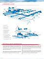
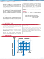
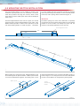
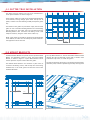
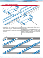
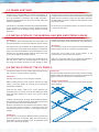
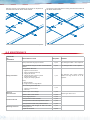
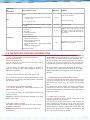
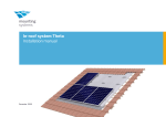
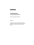
INSTALLATION
GUIDE
Solatop
TM
PV INTEGRATED ROOF SYSTEM
BEFORE YOU START
Carefully read these instructions. If you do not have all the necessary tools or information, contact Stratco for advice. Before starting
lay out all components and check them against the delivery docket.
TOOLS REQUIRED
•
•
•
•
•
Drill & Hex Adaptor
Allen Keys
Spanner Set
Large Square
Markout Pen
•
•
•
•
•
String Line
Tape Measure
Tin Snips
Gloves
Ladder
•
•
•
•
Hammer
Side Cutters
Wire Strippers
MC4 & MC3 Crimping
• Silicone Gun
• Screw Driver
• Masonary Drills
GENERAL SAFETY INFORMATION
Installers are to take suitable precautions when working on roof tops and should abide by all local regulations.
The installation guide does not document all responsibilities or requirements of the installer/electrician. It is the installer’s responsibility
to follow all local OH&S, electrical codes and regulations.
The installer assumes the risk of all injury that might occur during installation.
COMPONENT LAYOUT
2
3
1
4
7
11
1 - Mount Batten
8
2 - Solatop™ PV Panel
9
3 - Outer Gutter Tray
6
4 - Inner Gutter Tray
5 - Bottom Mount Bracket
6 - Top Mount Bracket
10
13
7 - Sarking Membrane
8 - SHCS M6x16 S/S
5
9 - 6mm Spring Washer S/S
10 - 12x20 Self Drilling Screw
11 - Existing Roof Rafter
12 - Panel Support Bracket Type 1
12
13 - Panel Support Bracket Type 2
ELECTRICAL SAFETY INFORMATION
All wiring and circuit connections are to be performed by a
suitably qualified electrician following sound electrical practice
for AC and DC circuits. Contact with electrically active parts of
the panels and system, such as terminals can result in sparks,
injury, fire burns and lethal shock whether the module is
connected or disconnected.
Short circuits in a DC circuit can cause electrical arching, which
can seriously burn and is a fire hazard. Do not cut any DC wires
or stick conductive objects in to connectors or junctions.
Disconnecting circuits or components of a DC circuit, while
under load or when generating power, can cause arching which
may not be self extinguishing. Before disconnecting connectors,
place a blanket over the panels to eliminate exposure to sunlight,
to stop the DC current flow.
Do not use damaged modules. Check each module for damage
to the back sheet of the Solatop PV panels and discard any
module with scratches or cuts. Damaging a back sheet can
cause a fire risk and will void the panel’s warranty.
Isolation boxes are required to be installed as close to the panel
array/strings as possible and in an accessible position if the
array/strings have to be disconnected from the inverter in an
emergency. Refer all local regulations and electrical codes when
evaluating a suitable location.
The Solatop PV panel is supplied with pre-wired MC4 connectors.
Do not terminate or cut these connectors during installation.
Only use pre-wired extension leads with MC4 connectors
installed. Contact Stratco for the supply of a range of lengths,
for connection leads and multi-way junction connectors.
Make sure all Solatop PV panels are disconnected when wiring
the isolation boxes and isolation box string connection
leads. Solatop PV panels have been designed for residential
applications. Do not use mirrors, magnification equipment or
other means to artificially concentrate sunlight onto the Solatop
PV panels.
Make sure the work site is dry and clean before and during the
installation.
Do not apply adhesives or paint to the underside or top of the
Solatop PV panels.
Never attempt to disassemble the Solatop PV panels or remove
the serial number plate on the underside of panel. Lift and carry
the Solatop PV panels from the edge of the glass only. Do not
attempt to lift or carry while holding the junction box or by the
wiring.
IMPORTANT
The installation is to conform to the following Australian
Standards;
AS/NZS 5033:2005 - Installation of Photovoltaic
(PV) Arrays
AS/NZS 3000:2007 - Electrical Installations
AS/NZS 4777:2005 - Grid Connection of Energy
Systems via Inverters
1.0 INTRODUCTION
The installation guide is intended for experienced solar installers
or individuals who have been suitably trained and qualified.
Photovoltaic installations must only be connected to the public
electricity grid by licensed electricians.
Note: The electrical voltages at solar installations connected to
the grid are usually life-threatening, and improper installation
can also result in fire.
levels and bolting locations before cutting, screwing or bolting
structural members.
It is recommended that the persons erecting the structure
have had some previous building experience because some
modifications to the existing house structure are required.
Stratco disclaims all liability for damages caused by inadequate
planning or faulty installation.
Please read these assembly instructions thoroughly before
commencing the construction. Double check all dimensions,
1.1 DIMENSIONS
33
6
943
172
970
3
1100
33
25
3
25
1.2 SPECIFICATION
The Solatop PV panels consist of silicon solar sells, clear glass,
EVA (ethyl vinyl acetate), a highly durable plastic rear film (tedlar
composite), tin-plated copper soldering ribbons, semiconductor
bypass diodes, connecting cables and connectors).
SOLATOP™ PV PANEL ELECTRICAL SPECIFICATIONS
MODEL
Numer of Cells
Size of Cells
Solatop PV panels are supplied with prewired flying leads with
MC4 connectors, for series connection of multiple Solatop PV
panels.
The Gutter Trays, Roof Battens and Panel Support Brackets
consist of Zinc/AL coated mild steel. The Panel Mount Brackets
are made from plastic coated aluminium.
Cell Type
Panel Construction
Nominal Mass
Overall Size
Wp
STBPM165105
42 in Series
125mm x 125mm
Mono - Si
Glass/EVA/Cells/EVA/Backsheet
14kg
943mmx970mm
x35mm
105W
All electrical specifications are at standard test conditions
(AM1.5, 1000±50W/m2, 24±oC). The current output of the
module shown in the Electrical Specifications Table is measured
at Standard Test Conditions and all electrical specifications will
have a variation tolerance of ±5%. These conditions may not be
frequently observed in actual practice.
Vmp
21.26V
Voc
26.49V
Impp
4.94A
Isc
5.29A
System Vmax
1000V
Under normal conditions, a photovoltaic module is likely
to experience conditions that produce more current and/or
voltage than reported at standard test conditions. Accordingly,
the values of Short-Circuit Current and Open-Circuit Voltage
marked on the module should be multiplied by a factor of
1.25 when determining component voltage ratings, conductor
current ratings, fuse sizes, and size of controls connected to
the PV output.
Open-Circuit Voltage
(%/deg C) & (mV/deg C)
IMPORTANT
Maximum Series Connections = System Vmax / Voc
Maximum Parallel Connections = Over Current (A) / (Isc×1.25)
Connection Cable
Temperature Rating
Bypass Diode Rating
Junction Box
Max Rated Current
Junction Box
IP Rating
Connection Cable Type
Connection Cable
Maximum Voltage
-0.33% / k
12A
Over Current Protection 10A
65
PV1-F1x4.0mm2
-40 to + 85ºC
1000V
Fire Rating
C
Application Class
A
1.3 HANDLING AND TRANSPORT
All components should be handled with care. The Solatop PV
panels are particularly breakable.
The electronic equipment (junction boxes, power inverters,
sensors etc) should be stored in a dry place.
During transport, unloading, intermediate storage and
installation they must be handled with great care. The electrical
connectors on the modules need to be protected against contact
with water (rain, snow etc).
The Gutter Tray’s need to be protected against physical damage
and excessive bending during the handling of long sections
should be avoided due to the risk of breakage and injury.
1.4 ELECTRICAL CONNECTIONS, CABLE TYPES
Each Solatop PV panel has flying leads pre-wired to the
connection box, with MC4 connectors wired to each end of the
lead.
Shielded cable with an adequate cross-section, intended for use
with solar installations is recommended for connection of the
marshalling, isolation and power inverters.
Array connections to the marshalling box or junction connectors
are to be made with original MC4 leads and junction connectors.
Do not cut the flying leads, under any circumstance.
The connectors between the modules are to be MC4 connectors.
1.5 EDGE CONTACTS AND CONNECTIONS
Edge connections should usually be dealt with by a tinsmith or
roofer. This covers the flashings, ridge covering, eaves, insect
shields, inflow sheets, skylight edges, chimneys, dormers etc.
Junctions with normal roofing materials require prior inspection
and planning, and should be carried out under the auspices of
an expert who is authorised to carry out the related operations.
Materials for these edges (for example titanium zinc, copper,
galvanised tin etc) should be selected in accordance with
materials used on the roof.
IMPORTANT
The Gutter Tray’s are only large enough to cope with water that
runs over the edge of the modules. They should not be used as
“collective” water channels under any circumstances.
It is also of absolute importance that the collected water is never
channelled directly into the Gutter Tray’s but onto the middle of
the module (small amounts) or even better into other channels
appropriate to the task.
2.0 INTEGRATION INTO AN EXISTING ROOF & WIND LOAD CAPABILITIES
The builder or council is to ensure the existing house/structure
is of a suitable structural integrity and complies with all the
relevant Australian Building codes and standards.
Materials for these edges (for example titanium zinc, copper,
galvanised tin etc) should be selected in accordance with
materials used on the roof.
Roof structure suitability is based on the Solatop PV panels,
Panel Mount Brackets, Mounting Batten, Panel Support Bracket
and Gutter Tray’s having a combined mass of 25kg per 1m2.
The Solatop PV panel system has been engineered for
residential applications in accordance with AS4055-2006 Wind
loads for housing. The system can withstand loads from wind
class, up to and including, N4 and a maximum wind speed of
50m/s (permissible). Refer to your local authorities for wind
classification in the specific installation site area.
The roof rafters are to have a maximum spacing of 1200mm
and to be in sound condition to withstand the systems mass and
environmental loading.
Due to fire hazards, a fire resistant barrier will be required to
be installed between the Mounting Battens and Rafters. Fire
resistant barriers, similar to sarking membranes and sealing
tapes, have to comply with local requirements and building
codes for fire resistance and stability.
For more information regarding the suitability of the house
structure to accommodate the Solatop PV panel system, consult
a structural engineer or a building authority. It is the builder’s
responsibility to ensure that the existing house roof structure
is capable of withstanding additional loads imposed by the
Solatop PV system.
2.1 POTENTIAL APPLICATIONS
In principle, Solatop PV panels can be installed on any roof
with a minimum slope of 20º and facing the equator. It can
occupy entire roof surfaces or just a portion of the roof surface,
meaning that there are an almost unlimited number of potential
configurations. Roofs with a slope of less than 20° should be
assessed individually. As far as possible, roofs should not lie in
the shadow of trees, neighbouring buildings or other objects on
the roof itself, otherwise performance will be correspondingly
reduced. It may be necessary to plan for the use of dummy
elements for optimum aesthetic value.
2.2 REQUIREMENTS FOR THE SUB-ROOF AND BATTEN CONSTRUCTION
The Solatop PV panel system requires ventilation between the
overlapped panels, whilst being as water tight as possible. A
fire proof sarking membrane is recommended to be installed
on top of the rafters, making sure the sarking membrane is
lapped from the top, downwards and sealed with the tape at the
lapping joint, to resist water penetration and fire hazards.
The sarking membrane is to be installed across the roof rafters,
loose enough to allow air flow underneath the Solatop PV panels,
but without the possibility of pooling water.
Allow at least 150mm of overlap between the sheets of the
sarking membrane. The sarking membrane will need to exit and
attach into the gutter, without any pooling area’s in front of the
fascia.
The Mounting Batten has been specifically designed for the
Solatop PV panel system. The Mounting Batten spacing and
placement is extremely important to the finished product. The
batten layer must be planar and should be carefully levelled if
needs be.
3.0 MOUNTING BATTEN INSTALLATION
The first Mounting Batten is to be installed as shown in the
installation layout provided for each installation. The batten
needs to be parallel to the ridge line or fascia, which in most
cases will be the most visible aspect of the roof and Solatop PV
panel system.
The Panel Support Bracket can be used as a spacer, as its overall
length is 832mm. Fasten the Mount Batten to each rafter, using
Buildex® Batten Zips®(M5.5 x40mm) or the equivalent, on each
side of the Mounting Batten, as shown in Figure 1. The battens
are to be installed past the end panels and onto the adjacent
rafter.The proceeding mount battens are then installed parallel
to the first, with a spacing distance of 832mm (Figure 2).
IMPORTANT
The batten spacings are of the exact dimensions as specified,
to guarantee the correct overlap. If the battens are not installed
parallel to the first batten, the Solatop PV panels will not
maintain a neat parallel appearance across the roof.
Panel Support Bracket
832
M5.5 x 40mm
Figure 1
832
832
832
Figure 2
When a batten run is longer than 4.0m, additional battens are to
be installed against the previous batten. A Batten Joiner bracket
is used to tie both battens together. The batten joiner is to be
Batten Joiner
fastened to both battens using 12x20mm self drilling screws, as
shown in Figure 3. Use a string line on the rear face of the batten
to make sure the battens are straight when joined together.
12x20
Self Drilling
Screws
Figure 3
3.1 GUTTER TRAY INSTALLATION
The Outer and Inner Gutter Trays are to be installed with a
centre pitch of 958mm as shown in Figure 4.
The first outer gutter tray needs to be positioned perpendicular
to the battens, leaving enough space above the top row of
panels, to make sure that a flashing suitably overlaps the gutter
tray.
The bottom of the gutter tray will either empty into the roofs
gutter or onto a transition flashing between the roof cladding
and the gutter tray. The Gutter Trays are to be fastened to the
Mounting Battens with 10x16mm self drilling screws (with
neoprene washers), along the centre of the Gutter Tray.
NOTE : Each gutter tray should be checked to be perpendicular
to the battens, to make sure the Solatop PV panels maintain a
neat appearance across the roof.
958
958
Figure 4
3.2 MOUNT BRACKETS
The Bottom Mount Brackets are placed over the top of the Mount
Battens and positioned 100mm in from the Panel Support
Bracket, as shown in Figure 5. A spare Mount Bracket can be
used to space the required 100mm from the gutter.
The Bottom Mount Brackets are fastened in place with (4)
12x20mm self drilling screws, with the top two screws being
installed first, in the small groove and then the front screws
installed afterwards.
The Top Mount Bracket is slid into the Bottom Mount Bracket
through the side and fastened in place with 2 stainless steel
socket head cap screws, as shown in Figure 6.
The top row of panels will require a row of panel mount brackets
above the panel, to allow a top flashing to overlap the top panel.
100
100
Figure 5
Figure 6
3.3 PANEL SUPPORT BRACKET
Figure 7
The Panel Support Brackets are to be positioned in line with
the inner flat surface of adjoining mount brackets. Holding a
straight edge ruler agains the inner flat surface of the mount
bracket, slide the Panel Support Bracket down to align its
bottom edge with ruler, FIgure 7.
The Panel Support Brackets are supplied in a left and right hand
configuration.
be mounted as close to the Gutter tray edge as possible. Each
Panel Support Bracket is to be fastened to the Gutter Tray with
(3) 10x16mm self drilling screws (with neoprene washers), as
shown in Figure 8.
Install the remaining Panel Support Brackets, against the edge
of the brackets above. The placement of the Panel Support
Brackets is important to make sure the panels are lapping and
alignment is consistent along the roof.
Figure 8 shows the correct orientation of the bottom fold which
mounts to the Gutter Tray. The Panel Support Brackets should
Figure 8
3.4 FRAME EARTHING
An earth lead is to be attached to one of the Mount Battens, to
avoid the hazards of electric shock or fire. The mounting frames
are to be grounded in accordance with AS/NZS 5033:2005 Installation of Photovoltaic (PV) Arrays and AS/NZS 3000:2007
- Electrical Installations.
The bolt and nut must be stainless steel and a thread size of M5.
A stainless steel star washer is to be mounted between the Mount
Batten and wire connection, making sure the washer penetrates
the Mount Battens protective coating to make electrical contact
with the bare metal.
A 6mm hole is to be drilled in the bottom lip of the Mount Batten,
for the connection of a earthing connector. Bonding shall be of
positive means, such as clamping, riveting, bolting or screwed
connectors.
The earth wire is to be double insulated, UV resistant and have
a size greater then 6mm2.
3.5 INSTALLATION OF THE MARSHALLING BOX AND STRING CABLES
IMPORTANT
The installation of the Marshalling box and string cables can
only be performed by a licensed and certified PV system installer.
It is important to plan the location of the Marshalling Box and
the routing of the string cables, before installing the Solatop PV
panels. On residential installations, the Marshalling Box can be
mounted in an accessible position under the eaves of the roof,
as close as possible to the Solatop PV panels.
Mount the Marshalling Box to the wall, using suitable fasteners
and wall anchors. Refer the electrical diagram for details of
the string and parallel connections of the Solatop PV panel
installation. Route the string connector cables through the eaves
and the roof members, to the location of the string connections.
IMPORTANT
It is important to route the string cables to the Marshalling Box
before installing the panels, to minimise panel handling.
Connect the string cables to the circuit breakers in the
marshalling box, as per the electrical diagram.
Make sure all exposed cables are in conduit and protected as
detailed in AS/NZS 5033:2005 and AS/NZS 3000:2007.
3.6 INSTALLATION OF THE PV PANELS
The Solatop PV panels are to be installed beginning with the top
row, so there is no need to walk on the panels.
IMPORTANT
Standing on the panels can cause the glass to shatter.
IMPORTANT
Do not remove the connectors from the cables. Stratco can supply
prewired cables for isolation boxes and junction connectors for
parallel connections outside of the marshalling boxes.
INSTALLATION PROCESS
Before installing the first panel, organise and plan the cable
routing, so that the panels do not have to be removed for
cabling after installation.
Carefully slot the panels up under the Panel Mount Brackets
above the panel.
Route the first panel’s cables in the correct directions for
connection to the next panel and to the marshalling box cable.
Route the cables between the Gutter Trays and the sarking
membrane.
Carefully push the panels up under the Panel Mount Brackets
above the panel, so that the bottom of the panel can be placed
in the hook section of the Panel mount bracket.
Repeat this procedure for the remainder of the panels, making
sure the correct number of panels is connected in series and
the parallel connections are correct, to the supplied electrical
diagram.
IMPORTANT
Each panel has a set of polarity dependent cables, which should
never be removed or cut through. Make sure that the routing
of the cables are not in the Gutter Tray or any path which could
lead to the cables being damaged.
Figure 9
Slide the panel up so the bottom of the panel can be placed in
the hook section of the Panel mount bracket.
The panel can then slide down securing into the hook section of
the Panel mount bracket.
Figure 10
Figure 11
4.0 MAINTENANCE
SUB-SYSTEM
OR
COMPONENT
MAINTENANCE ACTION
FREQUENCY
REMARKS
Verify mechanical integrity of conduits.
5 years
Any damaged conduit is to be replaced.
Verify insulation integrity of cables installed without
conduit.
5 years
Any damaged cable is to be replaced.
1 year
Any defective seals, clamps, blocking
diodes and surge arresters are to be
replaced.
Check junction boxes for:
Wiring Installation
1.
2.
3.
4.
tightness of connections
water accumulation/build up
integrity of lid seals
integrity of cable entrance, glands
and/or conduit sealing
5. integrity of clamping devices
Verify;
a) blocking diodes
b) surge arresters for degredation
Check earthing connections for;
1. tightness of connections
2. corrosion
Electrical
Charachteristics
Protective Devices
Mounting Structures
1 year
Measure open circuit voltages.
1 year
Measure short circuit currents.
1 year
Verify integrity of fuses.
1 year
Verify operation of CBs and RCDs.
1 year
Verify operation of earth fault protection system.
1 year
Verify operation of solar array isolation device.
1 year
Verify tightness and integrity of bolts and other
fastening devices.
1 year
Inspect for corrosion.
5 years
According to Section 6.2.1.
SUB-SYSTEM
OR
COMPONENT
MAINTENANCE ACTION
FREQUENCY
Verify;
Site
REMARKS
Clean site as required.
1. Cleanliness (accumulation of debris around and/
or under array).
1/4 year
Trim trees if required.
2. No shading of array.
Verify cleanliness (accumulation of dust or fungus
on array).
1/4 year
Clean if necessary.
Check for visual defects including;
1.
2.
3.
4.
fractures
browning
moisture penetration
frame corrosion
1 year
Modules with visual defects should
be further inspected for performance
and safety to determine the need for
replacement.
1 year
And defective seals, clamps and bypass
diodes are to be replaced.
Inspect junction boxes for:
PV Modules
1.
2.
3.
4.
tightness of connections
water accumulation/build up
integrity of lid seals
integrity of cable entrance, glands and/or conduit
sealing
5. integrity of clamping devices
Verify bypass diodes
5.0 IMPORTANT FURTHER INFORMATION
5.1 SAFETY PRECAUTIONS AND INSTRUCTIONS FOR WALKING ON THE ROOF
General safety precautions;
1. Do not touch the PV elements with metal items such as
hammers, screwdrivers etc.
Serial Number: Each Solatop Panel has a unique serial number
which consists of 16 characters for product traceability. The
8th and 9th digits are the year of manufacture. The 10th and
11th digits are the month of manufacture. The 12th digit is the
batch number, and the last 4 digits are the sequence number.
2. Do not damage the cables (High voltage, up to 800V): if
necessary, arrange for cables with damaged insulation to be
replaced by a specialist.
The serial number is permanently attached to the interior of
the module, and is visible from the top of the panel. DO NOT
REMOVE ANY LABELS. Removing labels will void the product
warranty.
3. Never disconnect connectors when under electric load
4. Try to avoid carrying tools on the belt when working near the
PV elements (risk of damaging the modules if tools are dropped
onto the glass surface).
5.2 EMERGENCY SHUT DOWN PROCEDURE
1. Turn off the INVERTER A.C. MAIN SWITCH located in the
isolation enclosure.
2. Turn off the PV ARRAY DC MAIN SWITCH located in the
isolation enclosure.
WARNING: do not open plug and socket connectors or PV string
isolators under load.
5.3 PRODUCT IDENTIFICATION
Each Solatop Panel has two labels on the rear side to provide
the following information:
Nameplate: Documents the panels electrical and physical
specifications.
5.4 COMMISSIONING AND PERIODIC MAINTANANCE
In accordance with AS/NZS 5033:2005, commissioning tests are
required to ensure that the PV array complies with the safety
requirements. See section 5.2.1 for required commissioning
tests.
The maintenance section outlines the periodic maintenance
requirements, as well as the frequency of maintenance checks
required to keep the Stratco roof Mounted Solar Panels working
at optimum capacity.
5.4.1 OPEN CIRCUIT VOLTAGE
This test is intended to ensure that the wiring polarity and
continuity of the PV array are correct.
The open circuit voltage of every string shall be measured
before connecting to other strings. All PV string open circuit
voltages shall be within 5% variation; otherwise the connections
shall be verified for polarity, continuity and possible faults and
repaired. Once the verification is complete and satisfactory, the
PV strings may be connected in parallel.
CONTACT
1300 165 165
The same procedure shall be carried out to verify PV sub-array open circuit voltages
(if relevant) and PV array open circuit voltage before connecting the PV array to the
PCU.
Notes:
1. All measurements should be made when practicable under stable irradiance
conditions. Conditions close to solar noon are preferable.
2. A guideline on open circuit voltage measurements for large PV arrays (>20 strings)
where the environmental conditions may change significantly during measurements
is given in AS/NZS 5033:2005 Appendix I.
3. Typically, this voltage should be the number of modules in the string times the
voltage of one module.
Signed_____________________________
Date __/__/_____
5.4.2 SOLAR ISOLATION DEVICE TEST
The operation of the solar isolation device shall be verified, when present.
The testing procedure shall be;
1. With the PV array in normal operation under irradiance conditions greater than
500 W/m², operate the solar isolation device according to the instructions posted
next to it and verify the PV array has been disconnected from the system.
Signed_____________________________
Date __/__/_____
2. Operate the reset facility according to the installer’s instructions and verify that
the PV array re-connects to the system.
Signed_____________________________
Date __/__/_____
5.4.3 SHUT DOWN PROCEDURE AND FIRE SAFETY LABELS
The emergency shutdown procedure sticker, and fire safety label shall be attached
to the main switchboard, in such a position as to be easily visible.
Signed_____________________________
Date __/__/_____
BROCISO
© Copyright February 2012
All brands and logos/images accompanied by ® or ™ are
trade marks of Stratco (Australia) Pty Limited.
www.stratco.com.au