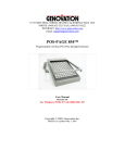
1
USER GUIDE
INDEX
Introductionp.6
Getting Started
p.8
Operating the DX1000p.10
Operational Examplesp.12
Gain Inputp.12
Xover Allp.13
Gain Outputp.15
Low Cutp.17
Low Delayp.18
Phase Allp.19
Limiterp.20
CD Hornp.22
Description of Features
Input Gain & Output Gain
p.24
2/3/4 Way Crossoverp.24
Phase Inversep.24
Low Cutp.24
Limiterp.25
CD Hornp.25
Delayp.25
Stereo On/Offp.25
LF Sump.26
Control Lockp.26
Audio Connections
2 Way Modep.27
3 Way Modep.28
4 Way Modep.28
Specificationsp.29
Crossover frequenciesp.29
Inputp.29
Outputp.29
A/D Performancep.30
D/A Performancep.30
System Perfomancep.30
Function Switchesp.30
6
INTRODUCTION
Congratulations on the purchase of your STONEWATER DX1000
digital audio crossover. We are confident that this product will meet
the high standards you have come to expect out of Stonewater
products. The DX1000 offers you the following features.
• 2/3/4 way crossover mode operation selectable with back panel
switches
• Output gain for each output
• Phase inverse option on all outputs
• Low Cut filter for each channel
• Limiter for each output
• CD horn equalization on high output channels
• Delay option for low output channels
• Distribute your mono input signal to two outputs
• Low summed output for mono sub woofer applications
• Level meters for input channel with clip indicator
• Control Lock for prevention of accidental parameter change
during operation
7
• LED’s on front panel to indicate the operational mode
• LCD display showing accurate parameter and information display
• Full digital front panel user interface with glow buttons
8
GETTING STARTED
Make sure the rear panel switches are set according to the desired
MODE of operation and control lock button is not engaged.
Plug the AC power cord (provide with the unit) to the AC power input
socket on the rear panel as shown above and turn ON the unit. The
glow buttons on front panel will light up for few seconds flashing
the unit’s model number and brand name on LCD screen. Once the
DX1000 is ready the LCD screen shows the input level of both the
input channels.
1:
2:
The bars indicate the level of input signal to DX1000. If there is no
input to the DX1000 then there will no bars to display.
NOTE: The LCD screen will display the brand name and model
number of the unit if there’s no input signal present for more than 5
seconds.
9
10
OPERATING THE DX1000
Below shown is the front panel of DX1000
1
2
3
4
5
6
1&6 – Both channels have their individual set of buttons to control
parameters
(Note when in 4 way mode operation Channel 2 button won’t
allow to select parameters)
2–
LEDs to indicate the operational mode.
3–
16x2 LCD screen for parameter and information display
purpose.
4–
Data wheel to change selected parameter.
5–
Limiter button to change the threshold setting for each output
and CD horn equalizer to engage the horn EQ for high output
channels.
When changing any parameter for any particular channel press the
respective button. The LCD will display the parameter name and the
value. In order to change the value rotate the ‘Data Wheel’, press the
button again and look for more options or press ‘Data Wheel’ to exit.
When no other options are available under that button then LCD will
change back to input level display.
11
12
OPERATIONAL EXAMPLES
GaIn Input
This button helps to set the input signal gain for a specific channel
Step 1: Press the button ‘GAIN INPUT’ of channel 1 or channel 2
(if in 4way mode the channel 2 ‘GAIN INPUT’ will not respond).
The glow button will lit up and the LCD display will change.
Ch1 Input Gain
+03dB
Step 2 : Now rotate the ‘DATA WHEEL’ in order to change the input
gain value.
Step 3 : Again press the ‘GAIN INPUT’ or ‘DATA WHEEL’ to exit or
press any other button.
Once the above step is performed the GAIN INPUT button will stop
glowing.
13
XOver aLL
This button helps user to change the crossover frequencies for various
modes. The options available will depend on device operational mode.
2 WAY : Low/High Frequency.
3 WAY : Low/Mid Frequency, Mid/High Frequency.
4 WAY : Low/Low-Mid Frequency, Low-Mid/High-Mid frequency,
High-mid/High frequency.
(accessible only with Channel 1 ‘XOVER ALL’ button)
Let’s consider the device is in 3WAY mode.
Step 1 : Press the button labeled ‘XOVER ALL’.
The glow button will lit up and LCD display will change.
Step 2 : Rotate the DATA WHEEL to change the crossover frequency
point.
Low/Mid freq
100 Hz
14
Step 3: Again press the XOVER ALL button and the LCD display will
take you to next option.
Then follow STEP 2 to change the crossover point.
Mid/High freq
900 Hz
Step 4: Again press the XOVER ALL button, since there are no more
crossover points to be changed in 3 WAY mode the LCD will go back
to the input level display. During the above procedure you can exit by
pressing the DATA WHEEL or press any other parameter button.
After completion of the above steps the XOVER ALL button will
stop glowing.
15
GaIn Output
This button will enable the user to change the output gain for Low, Mid and
High outputs for the respective channel.
Step 1 : Press the ‘Gain Output’ button and the button will lit up. The gain
options provided by the system depends on the mode selection of the unit.
2 WAY : Low Output, High Output
3 WAY : Low Output, Mid Output, High Output
4 WAY : Low Output, Low-Mid Output, High-Mid
Output & High Output.
For this example lets assume the device is in 2-WAY mode.
Step 2 : The LCD will display the first parameter option, in this case LOW
OUTPUT. Rotate the ‘DATA WHEEL’ to set the output gain.
Ch1 Low Output
+06dB
16
Step 3 : Press the ‘Gain Output’ button again to access the next
parameter option HIGH OUTPUT and follow STEP 2.
Ch1 High Output
-06dB
Step 4 : Press the ‘Gain Output’ button or ‘DATA WHEEL’ to exit or
press any other parameter button. The ‘Gain Output’ button will
stop glowing.
17
LOW Cut
This activates a low cut filter with center frequency at 40Hz which is
applied to the respective input channel.
Once pressed the glow button will lit up and the LCD display will flash
the following message for few seconds before going back to level
meter display screen.
Lowcut ON
The glow button will keep glowing indicating the ‘LOW CUT’ filter is
turned ON for that channel. When pressed again the LOW CUT filter
will be turned off and will stop glowing after flashing the following
message for few seconds.
Lowcut OFF
18
LOW DeLay
Low Delay parameter enables user to set the delay time for LOW
OUTPUT.
Step 1 : Press the ‘LOW DELAY’ button and the button will lit up. The
LCD will display the following message.
Ch1 Low Delay
1.6ms
Step 2 : Rotate the ‘DATA WHEEL’ in order to change the time value.
Step 3 : When done press the ‘LOW DELAY’ button or the ‘DATA
WHEEL’ to exit. The ‘LOW DELAY’ button will stop glowing.
19
phase aLL
This button helps to change the phase of the output signals of the
respective channel.
Step 1 : Press the ‘PHASE ALL’ button and the button will lit up.
The LCD will show the parameter option based on the device
operation mode.
2 WAY : Low Phase, High Phase
3 WAY : Low Phase, Mid Phase, High Phase.
4 WAY : Low Phase, Low- Mid Phase, High-Mid Phase,
High Phase (only accessible by channel 1
‘PHASE ALL’ button)
Ch1 Low Ph Inv?
N
Step 2 : Rotate the ‘DATA WHEEL’ to change option to ‘Y’.
Step 3 : Once done press the ‘PHASE ALL’ button again to access
other options and follow STEP 2 or press ‘DATA WHEEL’ to exit.
If there are no more options to display DX1000 will return to the initial
level meter display and the ‘PHASE ALL’ button will stop glowing.
20
LImIter
The ‘LIMITER’ option enables the user to change the limiter threshold
parameter for each and every output channel based on the device
operational mode.
2 WAY : Ch1 Low Threshold, Ch1 High Threshold,
Ch2 Low Threshold, Ch2 High Threshold
3 WAY : Ch1 Low Threshold, Ch1 Mid Threshold,
Ch1 High Threshold, Ch2 Low Threshold,
Ch2 Mid Threshold, Ch2 High Threshold.
4 WAY : Low Threshold, Low-Mid Threshold,
High-Mid Threshold, high Threshold.
Step 1 : Press the ‘LIMITER’ button and the button will lit up, providing
the option as per the device operational mode. The LCD will display
the following message considering the device is in 2 way mode.
Ch1 Low Thresh
-06dB
Step 2 : Rotate the ‘DATA WHEEL’ in order to change the threshold
value.
Step 3 : Once done press the ‘LIMITER’ button in order to access the
next parameter and repeat STEP 2 or press ‘DATA WHEEL’ to exit.
21
If all the parameter options are exhausted then DX1000 will return to
level meter display, and the ‘LIMITER’ button will stop glowing.
22
CD hOrn
This button activates the CD HORN equalizer filter on HIGH output of
the DX1000.
Press the ‘CD HORN’ button, the button will lit up and the LCD screen
will flash the following message for few seconds.
CD Horn ON
The ‘CD HORN’ button will keep glowing indicating that the CD
HORN equalization has been turned ON.
To turn OFF the CD HORN press the button again LCD will flash the
following message and the button will stop glowing.
CD Horn OFF
23
24
FEATURES
Input Gain & Output Gain
DX1000 provide input gain for two input channels ranging from -24dB
to +6dB range and output gain ranging from -48dB to +12dB for each
channel.
2/3/4 Way Crossover
DX1000 can be operated in 2/3/4 way crossover mode and the
front panel buttons’ responses will change according to the device
operation mode.
Phase Inverse
Phase inverse option is provided for each output channel. When
speakers are not in phase comb filtering effects happens, so this phase
inverse will help you to get peak performance out of your system.
Low cut
DX1000 provide Low Cut filter at 40Hz for each low-output channels.
When activated on any channel the ‘LOW CUT’ button will keep
glowing indicating low cut is activated for that particular channel.
25
Limiter
Limiters in DX1000 are of great use especially when it comes to
protecting your speakers. Each output channel is provided with a
limiter whose threshold can be controlled by user ranging from -24dB
to 0dB.
CD Horn
CD horn equalizer helps to recover the higher frequencies lost from
horn speaker’s output response.
Delay
DX1000 has the provision to introduce a delay of maximum
2milliseconds on its low output channel. In case of multi-way system
if the drivers are not exactly aligned on the same vertical axis, the
varying distance between the sound source and listener can result
in comb-filtering effect. Using this delay the user can adjust the time
mis-alignment.
Stereo On/Off
This button is located at the rear panel of DX1000. When in ‘OFF’
position the crossover performs its normal function, when turned ON the
channel 1 crossover outputs are internally summed to channel 2 outputs,
thereby one can use DX1000 as audio distribution device as well.
26
Lf sum
LF sum button is located at the rear panel of DX1000, when turned
ON the low output of channel 1 provides the summed output of
channel 1&2’s low frequencies.
COntrOL LOCK
The control lock button at the rear panel when engaged locks the
front panel buttons and data wheel. This prevents from accidental
changes of parameter values. Even if someone presses the front
panel button while the control lock is engaged the LCD will flash the
following message for few seconds.
CONTROLS
LOCKED
27
AUDIO CONNECTIONS
8
7
6
5
4
3
2
1
Above shown is the section of audio input and output connectors on
the rear panel of DX1000.
Audio input and output connections for different modes of operation
are mentioned below.
2 Way mODe
1 – Channel 1 input
2 – Low frequency output from channel 1
3 – NOT USED
4 – High frequency output from channel 1
5 – Channel 2 input
6 – Low frequency output from channel 2
7 – NOT USED
8 – High frequency output from channel 2
28
3 Way Mode
1 – Channel 1 input
2 – Low frequency output from channel 1
3 – Mid frequency output from Channel 1
4 – High frequency output from Channel 1
5 – Channel 2 input
6 – Low frequency output from channel 2
7 – Mid frequency output from channel 2
8 – High frequency output from channel 2
4 Way Mode
1 – Channel 1 input
2 – Low frequency output from channel 1
3 – Low Mid frequency output from channel 1
4 – NOT USED
5 – NOT USED
6 – NOT USED
7 – Hi Mid frequency output from channel 1
8 – High frequency output from channel 1
29
SPECIFICATIONS
Crossover frequencies
2 WAY mode:
Low/High:
45Hz to 9.6kHz
3 WAY mode:
Low/Mid:
45Hz to 960Hz
Mid/High:
450Hz to 9.6kHz
4 WAY mode:
Low/Low-Mid:
45Hz to 960Hz
Low-Mid/High Mid: 450Hz to 9.6kHz
High-Mid/High:
450Hz to 9.6kHz
Input
Connector : XLR
Type: Balanced , Unbalanced (RF filter)
Impedance: >40kohms
Nominal Input Level: +4dBu
Maximum Input Level: +20dBu
CMRR: >60dB
Output
Connector: XLR
Type: Balanced, Unbalanced (RF filter)
Impedance: 200 ohms
Maximum output level: +20dBu
30
A/D Performance
Type: 24 bit Delta Sigma A/D Converter
SNR:99dB (Typical)
Dynamic Range: 99dB (Typical)
Sampling Rate: 48kHz
D/A Performance
Dynamic Range: >106dB A-weighted
System Performance
Dynamic Range: 106dB
THD+N: 0.002% Typical
Frequency Response: 20 – 24kHz
Processing: 32bit Floating point DSP
Function Switches
Rear Panel
LF Sum:
Selects normal or summed low frequency output from low output channel 1.
Mode:
Selects 2/3/4 way mode of operation.
Stereo:
Distributes the channel 1 outputs to channel 2 output channels (summed output).
Lock:
Locks the front panel buttons
31
Power Supply
Operating voltage:
160 VAC 50/60Hz to 230 VAC 50/60Hz
Power Consumption: 10 Watts
Physical
Dimensions:
1.75”H X 19”W X 6”D (4.45cm X 48.3 cm X 15.24 cm)
Weight:1.8 Kg
Note: Specifications subject to change.
For any additional information, please write in to reachus @ :
stonewaterindia.com
Note : Specifications subject to change without notice.
32