1
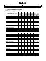
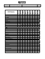
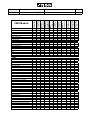
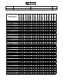
Edition
Manual
2005-05-04 Workshop Manual, Stiga Park
Chapter
1 General instructions
Workshop
manual
Park 2/4WD
2000-2008
Page
1
Edition
Manual
2008-05-19 Workshop Manual, Stiga Park
Chapter
1 General instructions
Page
1
1 General instructions
Contents in this chapter
1.1 Introduction ...............................2
1.1.1 Responsibility declaration ......2
1.1.2 How this manual is used .......2
1.1.3 Abbreviations .........................2
1.2 Safety Precautions ...................2
1.2.1 Symbols and general
warnings .................................3
1.2.2 Warm parts ............................3
1.2.3 Moving parts ..........................3
1.2.4 Lifting and blocking up ...........3
1.2.5 Cleanliness ............................3
1.2.6 Tightening torque ..................3
1.2.7 Sharp edges ..........................3
1.2.8 Replacement parts ................3
1.2.9 Inspection ..............................3
1.3 Guarantee ..................................4
1.3.1 Guarantee period ..................4
1.3.2 Extended guarantee ............. 4
1.3.3 Component guarantee,
chassis .................................. 4
1.3.4 Exeptions .............................. 4
1.3.5 Conditions for validity of
the warranties ........................ 4
1.4 Unpacking and assembly ........ 5
1.4.1 Unpacking ............................. 5
1.4.2 Battery .................................. 6
1.4.3 Assembly .............................. 8
1.4.4 Final checks .......................... 12
1.5 Service ...................................... 13
1.6 Technical specifications ......... 21
1.6.1 Machines .............................. 21
1.6.2 Motors ................................... 28
1.6.3 General tightening torque ..... 28
1.7 Instructions for use .................. 29
General
This Workshop Manual is intended for Stiga Park models 2000-2007. The article numbers
and product names are designated in the tables under “Technical specification” at page 21.
This Manual do not cover repair instructions for the motors. Regarding motors, contact the
respective representative in the actual country.
This Manual and its specifications are valid for machines in their original design. In case of
modified or changed machine, i.e. the motor is replaced, the manual accordance is limited.
The manual is divided in the following chapters:
Chapter 1 is this chapter
Chapter 2 Chassis
Chapter 3 Steering
Chapter 4 Hydraulic system
Chapter 5 Belts
Chapter 6 Control Wires
Chapter 7 Electrical system
Edition
Manual
2008-05-19 Workshop Manual, Stiga Park
Chapter
1 General instructions
Page
2
1.1 Introduction
1.1.1 Responsibility declaration
In spite of the great care we have taken there may be errors in this publication.
The author cannot be made liable for incorrect or missing information.
GGP SE reserves the right to regularly change product specifications without prior notice.
All the information in this book is based on the information available at the time of
production. Illustrations and photographs may be arranged schematically, which implies
that one picture may cover several models and therefore not correspond exactly with all
models.
1.1.2 How this manual is used
To make this manual easy to understand we have divided the machine into its main
systems and components. These parts are now the different chapters in the book.
Each chapter is divided up into sections.
There is a quick-guide on the cover of this book, which refers to the different chapters. In
each chapter there is a detailed table of contents so that you can easily and quickly find
what you are looking for.
For example, if you are looking for information on the Accessory Lifter you will find this in
chapter 3, Chassis and Body. On the first page in chapter 3 there is a detailed table of
contents which refers to the correct section, in this case section 3.1.
Always check that you are reading the right chapter for your particular machine before
starting the repair work.
1.1.3 Abbreviations
The following abbreviations are used in this manual:
HST Hydrostatic Transmission
PTO Power Take Off
1.2 Safety Precautions
This manual has been written primarily for trained mechanics working in a well-equipped
workshop. Nevertheless, the manual contains such detailed information that it can also be
of use to owners who wish to carry out simple service and repairs on their machine.
A basic knowledge of repairs, tools and repair instructions is, however, always a
prerequisite for first-rate results.
A qualified mechanic should always be consulted if the owner does not have sufficient
knowledge to carry out repairs.
During the warranty period all service must be carried out by an Authorised Workshop for
the warranty to be valid.
The following basic points should be observed if the machine is to function perfectly:
• Follow the service schedule.
• Be on the alert for sudden vibrations or abnormal noise to avoid major breakdowns.
• Always use Genuine Spare Parts
• Follow the descriptions in this manual carefully. Do not take any short cuts.
Edition
Manual
2008-05-19 Workshop Manual, Stiga Park
1.2.1 Symbols and general
warnings
Warning!
This symbol indicates a risk of
personal injury or damage if the
instructions are not followed.
Note!
This text indicates a risk of damage to
the material or risk of unnecessarily
complicated work if the instructions
are not followed.
1.2.2 Warm parts
Please observe that engine and exhaust
system picks up a lot of heat during use.
This applies above all to the silencer of
machines equipped with catalytic
converter.
To avoid injuries, allow the machine to cool
before any kind of repairs are made to or
near parts of the engine or exhaust
system.
1.2.3 Moving parts
The machines are all equipped with v-belt
transmissions. Always stop the engine and
remove the starter key before inspections
or repairs are carried out.
Always use extreme caution when testing
systems with moving parts to avoid
injuries.
Always use Genuine Spare Parts during
service work.
1.2.4 Lifting and blocking up
Before work under the machine, always
make sure that lifting devices and jackstands are approved for the weight.
Work safe!
Chapter
1 General instructions
Page
3
1.2.5 Cleanliness
Clean the machine before starting repairs.
Dirt that penetrates into sensitive
components can seriously influence the
service life of the machine.
1.2.6 Tightening torque
Unless otherwise stated the tightening
torque in the tables in the section
Technical specifications must be used for
the different sizes of screws. This does not
refer to self-tapping screws, which are
mainly used for the assembly of body
parts.
1.2.7 Sharp edges
Watch out for sharp edges, especially
when working with the mower deck. The
blades can be very sharp. Always wear
gloves when working with the blades.
1.2.8 Replacement parts
Always use Genuine Spare Parts during
service work.
1.2.9 Inspection
Each part dismantled in conjunction with
service work must be inspected.
Examine for: wear, cracks, out of
roundness, straightness, dents,
discolouring, abnormal noise and
jamming.
Edition
Manual
2008-05-19 Workshop Manual, Stiga Park
Chapter
1 General instructions
Page
4
1.3 Guarantee
1.3.1 Guarantee period
1.3.4 Exeptions
For consumer use: two years from date of
purchase.
For professional use: 200 hours or three
months, whichever comes first.
The extended warranty does not cover
damage due to the following:
• Neglect by users to acquaint themselves
with accompanying documentation.
• Carelessness.
• Incorrect and non-permitted use or
assembly.
• The use of non-genuine spare parts.
• The use of accessories not supplied or
approved by the manufacturer.
1.3.2 Extended guarantee
The guarantee period can be extended to
a maximum of 300 hours or 3 years from
the date of purchase provided that the
prescribed basic services have been
carried out at an authorised Stiga Service
workshop during the relevant guarantee
period. The services must be verified in the
service book.
1.3.3 Component guarantee,
chassis
Faults occurring in the machine’s bearing
in the articulated steering joint, as well as
the front and rear chassis, are covered by
a 10 year component guarantee from the
date of purchase
The guarantee is valid provided that the
prescribed basic services have been
carried out at an authorised service
workshop during the relevant guarantee
period. The services must be verified in the
service book.
Neither does the warranty cover:
• Wearing components such as blades,
belts, wheels,battery and cables.
• Normal wear.
• Engine and transmission. These are covered by the engine manufacturer’s warranties, with separate terms and
conditions.
The purchaser is covered by the national
laws of each country. The rights to which
the purchaser is entitled with the support of
these laws are not restricted by this
warranty.
1.3.5 Conditions for validity of the
warranties
The fully completed warranty card must be
sent to Stiga´s subsidiary or distributor.
In the event of a claim, the service history
must be confirmed with a copy of the
service book.
Edition
Manual
2008-05-19 Workshop Manual, Stiga Park
Chapter
1 General instructions
Page
5
1.4 Unpacking and assembly
Every Stiga Park has undergone an extensive
control programme before delivery. The
machines are delivered as completely
assembled as possible.
Thanks to this the assembly on delivery is rapid
and easy.
The correct and careful assembly of the
machine on delivery is a simple way of ensuring
satisfied customers!
Note!
The machine shall remain placed on the
pallet during the unpacking and
assembly.
1.4.1 Unpacking
Open up the crate and release the part as
follows:
1. Check the air pressure in the tyres. The
pressure is designated on the floor mat.
The air pressure in the tyres is of critical
importance for the performance and
handling of the machine. The correct air
pressure for mowing is 0.6 bar (9 psi) in the
front tyres, and 0.4 bar (6 psi) in the rear
tyres.
When using heavy accessories, e.g. snow
thrower, it may be necessary to increase the
pressure somewhat. However, the
maximum permitted pressure is always
Too high pressure
0.8 bar (12 psi).
Too high pressure in the tyres leads to that
the machine drives poor due to:
• A small surface in contact to the ground.
• Hard tyre = less flexibility = self cleaning characteristic deteriorate.
2. Remove the following parts from the
package and put them on the floor.
• The battery (some models).
• The steering wheel.
• The plastic bag, containing owners manuals,
information video and assembly screws.
Correct pressure
Edition
Manual
2008-05-19 Workshop Manual, Stiga Park
Chapter
1 General instructions
Page
6
1.4.2 Battery
The battery can be of the following two types,
depending on tha actual machine:
• Valve regulated type (A)
• Dry charged type (B)
Depending on the battery type, load and
assemble the battery, following the actual
instruction below.
A
Valve regulated battery
This battery needs limited maintenance. Is has
no electrolyte levels or plugs.
Warning!
Do not wear rings, metallic bracelet,
chain round the neck or similar metal
objects when working with the
battery. It can cause short-circuit,
burns and fire.
Warning!
The battery must be fully charged before being used for the first time. The
battery must always be stored fully
charged. If the battery is stored while
discharged, serious damage will occur.
Charging with the engine
The battery can be charged using the engine’s
generator as follows:
1. Install the battery in the machine as shown
below.
2. Place the machine outdoors or install an
extraction device for the exhaust fumes.
3. Start the engine according to the
instructions in the user guide.
4. Allow the engine to run continuously for 45
minutes.
5. Stop the engine. The battery will now be
fully charged.
A
B
Charging using battery charger
When charging using a battery charger, a
battery charger with constant voltage
must be used.
Ordering number: 1136-0602-01.
The battery can be damaged if a standard
type battery charger is used.
Edition
Manual
2008-05-19 Workshop Manual, Stiga Park
Chapter
1 General instructions
Page
7
Dry charged battery
Dry charged batteries are delivered without
battery acid in their cells.
Warning!
Filling with battery acid shall take
place in a well illuminated and
ventilated place with rapidly access
to fluiding water for rinsing.
Warning!
Wear rubber gloves and eye protection
and handle the acid with great care to
avoid spillage.
Warning!
The acid can burn the skin and destroy
clothing and other materials it comes
in contact with.
Warning!
Do not wear rings, metallic bracelet,
chain round the neck or similar metal
objects when working with the
battery. It can cause short-circuit,
burns and fire.
Maintain the dry charged battery as follows:
1. Fill carefully all cells with battery acid. The
acid level shall be ca 5 mm above the cell
packet edges.
2. Let the battery acid draw in into the cell
material during 20 minutes. Adjust after that
the cell levels again.
3. Let the battery stand for 2 hours before use.
During this time it is suitably to assemble the
rest of the machine as described below.
4. After 2 hours, install the battery as described
below.
Installation of battery
See also the respective installation manual,
delivered with the machine.
After the battery is charged, remove the motor
casing and install it in the machine. Connect
first the red cable to plus (+) and then the black
cable to minus (-).
If the cables are disconnected/
connected in the wrong order,
there is a risk of a short-circuit
and damage to the battery.
If the cables are interchanged,
the generator and the battery
will be damaged.
The engine must never be driven
with the battery disconnected.
There is a risk of serious damage to the generator and the
electrical system.
Edition
Manual
2008-05-19 Workshop Manual, Stiga Park
Chapter
1 General instructions
Page
8
1.4.3 Assembly
The assembly procedure shall take place in a
clean, well illuminated and dry place.
Assemble the machine as follows:
Assembly of steering wheel
Instructions for machines with mechanic
steering:
The machine is delivered with two shims, one
with a thickness of 0.5 mm and one with a
thickness of 1.0 mm.
In order to minimise the axial play in the
steering column, the shim washers (0.5 mm)
and/or (1.0 mm) must be installed on the
steering column between the steering column
jacket and the bracket as follows.
1. Install the steering column jacket on the
steering column and secure by knocking in
the tension pin approximately 1/3 of its
length.
2. Pull the steering column jacket and the
steering column up.
3. From the outside, check whether no
washers, the 0.5 mm washer, the 1.0 mm
washer or both washers can be inserted into
the gap. The washer/washers must not be
forced in, as there must be a little axial play.
4. Pull out the cotter pin and dismantle the
steering wheel jacket.
5. Install the washer/washers in accordance
with point 3 above.
Instructions for machines with hydraulic
steering:
6. Install the steering column jacket on the
steering column and secure by knocking in
the tension pin fully. Use a counterhold.
Also make sure that the logo on the steering
wheel is in the correct position.
1. Adjust the machine in the straight
forward direction.
2. Attach the steering wheel with the
logotype readable from the driver
position.
Edition
Manual
2008-05-19 Workshop Manual, Stiga Park
Chapter
1 General instructions
Page
9
Assembly of seat (adjusting knobs under)
Install the mounting in the rear (upper) holes as
follows:
H
1. Install the shoulder washers (E) on the
screws (F).
E
2. Insert the screws through the slots in the
bracket. Place a washer (H) between the
seat and the bracket.
F
3. Tighten the screws in the seat. Tightening
torque: 9±1.7 Nm.
If the screws are tightened more than
9±1.7 Nm, the seat will be damaged.
H
G
4. Check that the seat moves easily in the
slots in the bracket.
Install the mounting in the front (lower) holes as
follows:
1. Install a washer (H) on each knob (G).
2. Insert the knobs through the slots in the
bracket and tighten by hand in the seat.
3. Fold the seat down and place it in the
desired position.
4. Tighten the screw knobs (G) by hand.
The screw knobs (G) and the seat will
be damaged if tools are used.
Assembly of seat (adjusting wings under)
Release the catch (S) and fold up the seat
bracket.
Install the mounting in the rear (upper) holes as
follows:
I
1. Install the shoulder washers (F) on the screws
(K).
F
2. Insert the screws through the slots in the
bracket. Place a washer (I) between the seat
and the bracket.
I H
3. Tighten the screws in the seat. Tightening
torque: 9±1.7 Nm.
K
G
S
Edition
Manual
2008-05-19 Workshop Manual, Stiga Park
Chapter
1 General instructions
If the screws are tightened more than
9±1.7 Nm, the seat will be damaged.
4. Check that the seat moves easily in the slots
in the bracket.
Install the mounting in the front (lower) holes as
follows:
1. Install the screw knobs (H) on the screws (G).
2. Install a washer (I) on each screw.
3. Insert the screws through the slots in the
bracket and tighten by hand in the seat.
4. Fold the seat down and place it in the desired
position.
5. Tighten the screw knobs (H) by hand.
The screw knobs (H) and the seat will
be damaged if tools are used.
Assembly of seat (adjusting by lever)
1. Remove the following components from the
seat bracket:
• 4 Nuts (for transport locking, not used).
• 4 Screws.
• 4 Shoulder washers.
2. Position the seat over the mounting in the seat
bracket.
3. Install the shoulder washers on the screws.
4. Insert the screws with the attached shoulder
washers through the slots in the seat bracket
and the holes in the seat plate. Screw the seat
into place.
Tightening torque: 9±1.7 Nm.
If the screws are tightened more than
9±1.7 Nm, the seat will be damaged.
5. Check that the seat moves easily in the slots
in the bracket.
Page
10
Edition
Manual
2008-05-19 Workshop Manual, Stiga Park
Chapter
1 General instructions
Page
11
Arm rest (if applicable)
The arm rests and the installation components
are supplied in a separate box. Assemble as
follows:
1. Assemble the left and right mounts onto the
seat. Use 3 screws (Q) supplied at each
side.
Q
2. Assemble the arm rests with screws (R),
nuts (S) and spacers (T).
3. Tighten the screws so that the arm rests
simply can be folded up/down.
Towing plate
S
R
Fitting according to customer requirements.
Engine oil
Check the oil level in the engine and top up if
necessary.
HST oil
Check the oil level in the HST’s expansion tank
after test driving, and top up if necessary.
T
Edition
Manual
2008-05-19 Workshop Manual, Stiga Park
Chapter
1 General instructions
Page
12
1.4.4 Final checks
Removing from pallet
Steering chain / Steering wire
All the above measures shall have been done
with the machine standing on the pallet. Now,
loosen the remaining straps and roll off the
machine from the pallet.
Fit and adjust accessories.
Check that the steering chain / steering
wire is sufficiently taut. Adjust if
necessary.
Test driving
Warning!
Do not drive without a work
equipment (mover deck) attached.
Risk for turning over.
Drive the machine for a few minutes. Test all
the functions. Pay special attention to the
safety functions. If the machine is to be
delivered with mower deck or other
accessories, fit these before test driving the
machine.
HST oil
Check the oil level in the HST’s expansion tank
after test driving, and top up if necessary.
Miscellaneous
Give the machine a general inspection.
• Is the machine clean?
• Is there any oil leakage?
• Abnormal noise or rattle?
Receipt
By filling in the guarantee certificate you
guarantee that the delivery service has
been correctly conducted.
Remember to make sure that the
customer receives all the documentation
when the machine is collected / delivered.
Edition
Manual
2008-05-19 Workshop Manual, Stiga Park
Chapter
1 General instructions
Page
13
1.5 Service
Every new machine is delivered with a service book. This service book is part of the active
post-market programme and shall be kept in a safe place during the entire lifetime of the
machine. Hand over the service book if the machine is sold in 2:nd hand.
Service should generally be carried out at least every 50 operating hours (exception of the
first service), although in accordance with the conditions below.
There are three different grades of service events. Every service event consists of a
number of service points as described in the following paragraphs. Every service point has
a number which refer to a describing text after the schedules.
Some service points do not coincide with the scheduled service intervals, but shall be
performed in connection with a scheduled service when possible. E.g. some items shall be
performed at every second service and some also between two services. These service
points are described with procedure and interval in the respective “Instruction for use”.
Typical service points wich not coincide with scheduled service intervals are:
• Cleaning/changing air filter in some motors.
• Change of oil in some motors.
• Valve adjustments for some motors.
• Change of transmission oil in 4 WD machines.
• Change of spark plug in some motors.
Edition
Manual
2008-05-19 Workshop Manual, Stiga Park
Chapter
1 General instructions
Page
14
1.5.1 First Service
1.5.2 Intermediate Service
The first service shall be performed within 5
hours of running and includes the service
points as per the table below.
The intermediate service shall be conducted
between two basic services. That means:
This service is very important to safeguard
the continuing function of the machine.
Number
Service point
1
Safety check.
2
Tyres, air pressure.
3
Engine oil, change.
Machines with filter, replace it
together with the oil.
4A
Oil level in HST, check
(Valid for machines with HST
only).
5
Belt transmissions, check.
6
Steering adjustment.
7
Battery check.
21
Test driving.
*
Transmission oil, change and
tank filter/HST filter, clean.
(Valid for 4WD machines only)
*
Filter for transmission oli,
change. (Valid for 4WD
machines with external
hydraulic only)
*) See section 4.
For Pro Diesel: 100 hours after a basic
service.
For all other machines: 50 hours after a basic
service.
Number
1
2
3
4A
6
9
10
11
12
Service point
Safety check.
Tyres, air pressure.
Engine oil, change.
Oil level in HST, check.
(Valid for machines with HST
only).
Steering adjustment.
Air filter, cleaning.
Air filter catalytic converter,
cleaning.
Cooling fins, clean.
Lubrication
The intermediate service is not as extensive
as the Basic Service and can therefore be
conducted by the customer, or by an
authorised Service Workshop. Regardless of
who conducts the service, it must be
documented in the service book.
Edition
Manual
2008-05-19 Workshop Manual, Stiga Park
Chapter
1 General instructions
Page
15
1.5.3 Basic Service
The basic service shall be conducted as follows:
For Pro Diesel:
Every 200 hours or every
year, which first occur.
For all other machines:Every 100 hours or every
year, which first occur.
The Basic Service must always be conducted by
an authorized Service Workshop, and
documented with a stamp in the service book.
Number
Service item
1
Safety check
2
Tires, air pressure
3
Engine oil, change.
Machines with filter, replace it
together with the oil.
4B
Oil in HST, check/replace.
Machines with filter, replace it
together with the oil.
(Valid for machines with HST
only)
5
Belt transmissions, check
6
Steering adjustment
7
Battery check
8
Air filter for engine, clean/
replace
*) See also “Safety check”.
**) See also the mover deck manual.
***) See the motor manual.
Number
Service item
9
Air filter catalytic converter,
clean
(Valid for machines with
catalytic converter only)
10
Cooling fins, clean
11
Spark plug, check/replace
13
Transmission, check
14
Speed check
15
Bearing boxes, check**
16
Exhaust system, check*
17
Electrical system, check*
18
Mower deck, check**
19
Blades, check**
20
Power take-off, check
21
Control check
22
Valve play***
23
Test driving
Edition
Manual
2008-05-19 Workshop Manual, Stiga Park
Chapter
1 General instructions
Page
16
1.5.4 Description of service points
1. Safety check
Check the safety functions. It is often appropriate to do this check in conjunction with test
driving. The following items shall be checked at all machines:
• No leakage on fuel lines and connections.
• No mechanical damages to the electrical cables. All insulation intact.
• The muffler shall be undamaged and its screws tightened. No exhaust leakage in connections.
The electrical check items at the respective machine up to model 2004 are listed in the
tables below. For models 2005 and up, see the respective “Instructions for use”.
Senator, electrical safety check
Test Status
1 Brake pedal not pressed.
PTO activated.
No gear activated.
2 Brake pedal pressed.
PTO activated.
No gear activated.
3 Brake pedal not pressed.
PTO not activated.
A gear is activated.
4 Motor running.
PTO activated.
5 Motor running.
A gear activated.
6 Motor running.
Action
Result
Turn the key and make a Motor shall not
start attempt.
start.
Turn the key and make a Motor shall not
start attempt.
start.
Turn the key and make a Motor shall not
start attempt.
start.
Operator rises from the
seat.
Operator rises from the
seat.
Disconnect cable from the
shut off valve.
President and Comfort, electrical safety check
Test Status
Action
1 Brake pedal not pressed.
Turn the key and make a
PTO not activated.
start attempt.
2 Brake pedal pressed.
Turn the key and make a
PTO activated.
start attempt.
3 Motor running.
Operator rises from the
PTO activated.
seat.
4 Motor running.
Disconnect cable from the
shut off valve.
Motor shall
stop.
Motor shall
stop.
Motor shall
stop after a few
minutes.
Result
Motor shall not
start.
Motor shall not
start.
Motor shall
stop.
Motor shall
stop after a few
minutes.
Edition
Manual
2008-05-19 Workshop Manual, Stiga Park
Royal and Pro 16, electrical safety check
Test Status
1 Brake pedal not pressed.
PTO not activated.
2 Brake pedal pressed.
PTO activated.
3 Motor running.
PTO activated.
4 Cruise control activated.
5
Motor running.
Pro 20, electrical safety check
Test Status
1 Brake pedal not pressed.
PTO magnetic clutch not activated.
Chapter
1 General instructions
Page
17
Action
Turn the key and make a
start attempt.
Turn the key and make a
start attempt.
Operator rises from the
seat.
Operator rises from the
seat.
Result
Motor shall not
start.
Motor shall not
start.
Motor shall not
start.
Cruise control
shall
disengage
Disconnect cable from the Motor shall
shut off valve.
stop after a few
minutes.
Action
Result
Turn the key and make a Motor shall not
start attempt.
start.
2
Brake pedal pressed.
PTO magnetic clutch activated.
Turn the key and make a Motor shall not
start attempt.
start.
3
Motor running.
PTO magnetic clutch activated.
Operator rises from the
seat.
4
Cruise control activated.
5
Hydraulic lift in neutral position.
6
Motor running.
PTO magnetic
clutch shall
disengage.
Operator rises from the
Cruise control
seat.
shall
disengage.
Attempt to engage the
PTO magnetic
PTO magnetic clutch.
clutch shall not
engage.
Disconnect cable from the Motor shall
shut off valve.
stop after a few
minutes.
Edition
Manual
2008-05-19 Workshop Manual, Stiga Park
Pro Diesel, electrical safety check
Test Status
1
Brake pedal not pressed.
PTO magnetic clutch not activated.
Chapter
1 General instructions
Page
18
Action
Result
Turn the key and make a Motor shall not
start attempt.
start.
2
Brake pedal pressed.
PTO magnetic clutch activated.
Turn the key and make a Motor shall not
start attempt.
start.
3
Motor running.
PTO magnetic clutch activated.
Operator rises from the
seat.
4
Cruise control activated.
Operator rises from the
seat.
5
Hydraulic lift in neutral position.
Attempt to engage the
magnetic clutch.
PTO magnetic
clutch shall
disengage.
Cruise control
shall
disengage
PTO magnetic
clutch shall not
engage.
Edition
Manual
2008-05-19 Workshop Manual, Stiga Park
Chapter
1 General instructions
Page
19
2 Tyres, air pressure
11 Spark plug
Check the air pressure. Adjust if necessary.
The recommended air presure is
designated at the floor mat.
Remove the spark plug (not valid for Pro
Diesel) and clean it or replace if necessary.
See also the engine manufacturer manual.
3 Engine oil and oil filter
12 Lubrication
See the “Instructions for use”, delivered
with the machine or “Instructions for use” at
page 29. See also the engine manufacturer
manual.
Lubricate the articulation point (4 nipples)
and all moving parts such as wires and
levers. See also the instruction manual,
delivered with the machine.
4 Oil, HST
13 Transmission
See the “Instructions for use”, delivered
with the machine.
5 Belt transmissions, check
Listen for abnormal noise.
Manual models: Check that the drive
function works properly at all gears. Adjust
if required.
Check the condition of all the belts and belt
tensioners.
14 Speed check
6 Steering, adjustment
Check that the speed corresponds to the
specified value. See pages 18-22.
See section 3.
7 Battery, check
Valid for dry charged batteries only.
Check the acid level. Top up with distilled
water if necessary. See page 6-7.
8 Engine air filter
15 Bearing boxes
Listen for abnormal noise from the
bearings. Check that there are no wear,
play or seizure.
16 Exhaust system
See the “Instructions for use”, delivered
with the machine. See also the engine
manufacturer manual.
Check that there are no cracks, leakage or
other damages. Check the attachment
devices. See also the engine
manufacturer manual.
9 Catalytic converter air filter
17 Electrical system
See the “Instructions for use”, delivered
with the machine. See also the engine
manufacturer manual.
Check that there are no damaged cables,
contacts or other devices. Check that all
cables are properly secured to the chassis
and with cable holders. Check that there is
no friction between cables and chassis,
which can result in cable damage and
short circuit.
10 Cooling fins
Remove protective covers from the engine
and cleans between cooling fins. Use a
brush and compressed air. See also the
engine manufacturer manual.
Edition
Manual
2008-05-19 Workshop Manual, Stiga Park
18 Mower deck
Warning!
The blades are sharp. Always
wear gloves when working with
the blades to avoid injury.
Check if there are collision damages or
wear at the deck body and painting. Align,
repair and touch up the painting as
required.
Check the tightening of the bearing boxes
screws and tighten.
Chapter
1 General instructions
Page
20
20 Power take-off (PTO)
Check that the magnetic clutch (if
applicable) engage the work equipment
rotation in the desired time and that it not
slips during normal load. Replace the
clutch if necessary.
Check that the power take-off belt (if
applicable) engage the work equipment
rotation in the desired time and that it not
slips during normal load. Adjust if
necessary. See section 4.
Rotate the blades and check the the shafts
are correct, not bent, no abnormal bearing
noise and no plays.
Check that the power take-off brake (if
applicable) brakes the rotation movement
in the desired time. Adjust if necessary.
See section 4.
Check the belts and their tensions, see
section 4.
21 Control check
Check that the lifting mechanism moves
evenly, not jammed and no play and that it
locks in desired position.
Check that all controls function properly,
that there are no jammings or excessive
plays. Adjust if nesaccary. See section 5.
Check the electrical function of the
electrikal mower lifter (if applicable).
22 Valve play
Check the plastic guide bar between the
blades. Replace if required.
19 Blades
Warning!
The blades are sharp. Always
wear gloves when working with
the blades to avoid injury.
Check that the blades are sharp. Sharpen
as reqiured.
See the engine manual regarding
procedure and interval.
23 Test driving
Drive the machine during a few minutes
and make the following attentions in
different speeds and turnings in right and
left. Check that all functions work evenly
and proper and without any abnormal
noise.
• Brake function
• Clutch function
• Power take-off
• Steering
Check that there are no abnormal
vibrations.
Edition
Manual
2008-05-19 Workshop Manual, Stiga Park
Chapter
1 General instructions
Page
21
1.6 Technical specifications
STEERING
Servoassisted
Steering knob
Height adjustable steering wheel
Chain/wire
Chain/chain
SEAT
Backrest with additional height
Foldable armrest
Suspended seat
Comfort suspended seat
WHEEL
16"
17"
Double ball bearings
FEATURES
Mechanic PTO
Electrical PTO
Elektrical cutting height adj.
Speed cruiser
Switch and socket for rear rake
Harness for rear rake
Switch and socket for sand spreader
Pedal implement lifter
Pedal implement lifter, servoassisted
ROYAL
13-6114-11
13-6114-12
x
PRO 20
13-6221-11
13-6221-12
SPEED
Max speed km/h
x
PRO 18
13-6218-11
13-6218-12
TRANSMISSION
Gearbox 5+R
HST
Switchable differential lock
Wheel shaft dia
x
PRO 16
13-6216-11
13-6216-12
FUEL
12 litres
Fuel meter
External fuel cap
PRESIDENT
13-6113-11
13-6113-12
MOTOR
B&S I/C
B&S Vanguard
B&S Intek
Cylinders/Hp
COMFORT
13-6113-22
2000/2001 Models
SENATOR
13-6112-11
13-6112-12
1.6.1 Machines
x
x
x
x
2/16
2/16
2/18
2/20
x
x
x
x
x
x
x
x
x
K62
x
1"
K66
x
1"
11
13
x
x
x
x
x
x
x
x
x
x
x
x
x
x
x
x
x
x
x
x
x
x
x
x
x
x
x
x
x
x
x
x
x
x
1/12,5
1/15,5
1/12,5
x
x
x
x
x
x
x
x
x
K46
K46
K46
3/4"
3/4"
3/4"
3/4"
K62
x
1"
9
10
10
10
11
MST205
x
x
x
x
x
x
x
x
x
x
x
x
x
x
x
x
x
x
x
x
x
x
x
x
x
x
FUEL
Big Tank
Fuel meter
External fuel cap
TRANSMISSION
Gearbox 5+R
HST
Switchable differential lock
Wheel shaft dia
SPEED
Max speed km/h
STEERING
Servoassisted
Steering knob
Height adjustable steering wheel
Chain/wire
Chain/chain
SEAT
Backrest with additional height
Foldable armrest
Suspended seat
Comfort suspended seat
WHEEL
16"
17"
Double ball bearings
FEATURES
Mechanic PTO
Electrical PTO
Elektrical cutting height adj.
Speed cruiser
Switch and socket for rear rake
Harness for rear rake
Switch and socket for sand spreader
Harness for sand spreader
Pedal implement lifter
Hydraulic implement lifter
x
x
x
PRO DIESEL
13-6231-13
PRO 20 Cat
13-6221-23
x
PRO 20
13-6221-13
x
Page
22
PRO 16
13-6216-13
x
ROYAL
13-6114-13
x
POWER
13-6113-93
COMFORT
13-6113-23
MOTOR
B&S I/C Quiet
B&S Vanguard
Honda GCV 520
Hatz 1B40W
Cylinders/Hp
PRESIDENT
13-6113-13
2002 Models
Chapter
1 General instructions
SENATOR
13-6112-13
Edition
Manual
2008-05-19 Workshop Manual, Stiga Park
x
1/12,5 1/12,5
x
1/11
1/15,5
2/18
2/14
2/16
2/20
2/20
x
x
x
x
x
x
x
x
x
x
K66
x
1"
K66
x
1"
K66
x
1"
x
x
x
x
x
x
x
x
x
x
x
K46
K46
K46
K46
3/4"
3/4"
3/4"
3/4"
3/4"
K62
x
1"
9
10
10
10
10
11
12
12
12
x
x
x
x
x
x
x
x
x
x
x
x
x
x
x
x
x
x
x
x
x
x
x
x
x
x
x
x
x
x
x
x
x
x
x
x
x
x
x
x
x
x
x
x
x
x
x
x
x
x
x
x
x
x
x
x
x
MST205
x
x
x
x
x
x
x
x
x
x
x
x
x
x
x
x
x
x
x
x
x
x
x
x
x
x
x
x
x
x
x
x
x
x
x
x
x
FUEL
Big Tank
Fuel meter
External fuel cap
TRANSMISSION
Gearbox 5+R
HST
Switchable differential lock
Wheel shaft dia
SPEED
Max speed km/h
STEERING
Hydraulic servoassisted
Steering knob
Height adj. steering wheel
Chain/wire
Chain/chain
SEAT
Backrest with additional height
Foldable armrest
Suspended seat, pivot
Suspended seat, vertical
Comfort suspended seat
WHEEL
16"
17"
Double ball bearings
FEATURES
Mechanic PTO
Electrical PTO
Elektrical cutting height adj.
Speed cruiser
Switch and socket for rear rake
Harness for rear rake
Switch/socket, sand spreader
Harness for sand spreader
Pedal implement lifter
Hydraulic implement lifter
PRO 20 Cat
13-6221-24
x
x
x
PRO DIESEL
13-6231-14
PRO 20
13-6221-14
Page
23
PRO 16
13-6216-14
x
ROYAL
13-6114-14
x
POWER
13-6113-94
x
GOVERNOR
13-6113-84
x
x
Chapter
1 General instructions
PRESIDENT
13-6113-14
C UNLIMITED
13-6113-34
MOTOR
B&S mod 28
B&S mod 282H I/C
B&S Intek
Honda GCV 530
B&S Vanguard
Hatz 1B40W
Cylinders/Hp
COMFORT
13-6113-24
2003 Models
SENATOR
13-6112-14
Edition
Manual
2008-05-19 Workshop Manual, Stiga Park
x
x
x
1/12,5 1/15,5 1/15,5 1/12,5 1/12,5
x
x
x
x
1/11
1/18
2/14
2/16
2/20
2/20
x
x
x
x
x
x
x
x
x
x
K66
x
1"
K66
x
1"
K66
x
1"
x
x
x
x
x
x
x
x
x
x
x
x
x
K46
K46
K46
K46
K46
K46
3/4"
3/4"
3/4"
3/4"
3/4"
3/4"
3/4"
K62
x
1"
9
10
10
10
10
10
10
11
12
12
12
x
x
x
x
x
x
x
x
x
x
x
x
x
x
x
x
x
x
x
x
x
x
x
x
x
x
x
x
x
x
x
x
x
x
x
x
x
x
x
x
x
x
x
x
x
x
x
x
x
x
x
x
x
x
x
x
x
MST205
x
x
x
x
x
x
x
x
x
x
x
x
x
x
x
x
x
x
x
x
x
x
x
x
x
x
x
x
x
x
x
x
x
x
x
x
x
x
x
x
x
x
x
x
x
x
x
x
x
SPEED
Max speed km/h
STEERING
Hydraulic servoassisted
Steering knob
Height adj. steering wheel
Chain/wire
Chain/chain
SEAT
Backrest with additional height
Foldable armrest
Suspended seat, pivot
Suspended seat, vertical
Comfort suspended seat
WHEEL
16"
17"
Double ball bearings
FEATURES
Mechanic PTO
Electrical PTO
Elektrical cutting height adj.
Speed cruiser
Switch and socket for rear rake
Harness for rear rake
Switch/socket, sand spreader
Harness for sand spreader
Pedal implement lifter
Hydraulic implement lifter
PRO DIESEL
13-6231-15
PRO 20 Cat
13-6221-25
COMPACT
13-6101-15
COMPACT
HST
13-6103-15
POWER
13-6113-95
ROYAL
13-6114-15
PRO 20
13-6221-15
TRANSMISSION
Gearbox 5+R
HST
Switchable differential lock
Wheel shaft dia
Page
24
PRO 16
13-6216-15
FUEL
Fuel meter
External fuel cap
x
Chapter
1 General instructions
JUBILEE
13-6113-55
MOTOR
B&S mod 21
B&S mod 282H I/C
B&S Intek
Honda GCV 530
B&S Vanguard
Hatz 1B40W
Cylinders/Hp
PRESIDENT
13-6113-15
2004 Models
COMFORT
13-6113-25
Edition
Manual
2008-05-19 Workshop Manual, Stiga Park
x
x
x
x
2/16
2/16
2/20
2/20
x
x
x
x
x
x
K66
x
1"
K66
x
1"
K66
x
1"
x
x
x
x
x
1/15,5 1/13,5 2/14 1/12,5 1/15,5 2/18
x
x
x
x
K46
K46
K46
3/4"
3/4"
3/4"
10
10
10
x
x
1/11
x
x
x
K46
K46
K46
3/4"
3/4"
3/4"
3/4"
K62
x
1"
10
10
10
10
11
12
12
12
x
x
x
x
x
x
x
x
x
x
x
x
x
x
x
x
x
x
x
x
x
x
x
x
x
x
x
x
x
x
x
x
x
x
x
x
x
x
x
x
x
x
x
x
x
x
x
x
x
x
x
x
x
x
x
x
x
Dana
x
x
x
x
x
x
x
x
no
x
x
no
x
x
x
x
x
no
x
x
x
x
x
x
x
x
x
x
x
x
x
x
x
x
x
x
x
x
x
x
x
x
x
x
x
x
x
x
x
x
FUEL
Fuel meter
External fuel cap
TRANSMISSION
Gearbox 5+R
HST
Switchable differential lock
Wheel shaft dia
SPEED
Max speed km/h
STEERING
Hydraulic servoassisted
Steering knob
Height adj. steering wheel
Chain/wire
Chain/chain
SEAT
Backrest with additional height
Foldable armrest
Suspended seat, pivot
Suspended seat, vertical
WHEEL
16" x 6.00
16" x 7.50
17" x 8.00
Double ball bearings
FEATURES
Mechanic PTO
Electrical PTO
Elektrical cutting height adj.
Speed cruiser
Switch and socket for rear rake
Harness for rear rake
Switch/socket, sand spreader
Harness for sand spreader
Pedal implement lifter
Hydraulic implement lifter
Page
25
PRO DIESEL
13-6231-16
x
PRO 16
13-6216-16
COMPACT
13-6102-16
x
x
COMPACT
13-6103-16
COMPACT
13-6101-16
MOTOR
B&S mod 21
B&S mod 282H I/C
B&S Intek
Honda GCV 530
B&S Vanguard
Hatz 1B40W
Cylinders/Hp
Chapter
1 General instructions
ROYAL
13-6123-11
2005 Models
COMFORT
13-6122-11
Edition
Manual
2008-05-19 Workshop Manual, Stiga Park
x
x
x
1/15,5
2/14
x
x
x
K46
K46
3/4"
3/4"
10
10
1/12,5 1/13,5 1/15,5
x
x
x
K46
K46
3/4"
3/4"
10
10
2/16
x
1/11
x
x
Dana
x
x
x
x
x
x
x
x
x
x
x
3/4"
K62
x
1"
K66
x
1"
10
11
12
x
x
x
x
x
x
x
x
x
x
x
x
x
x
x
x
x
x
x
x
x
x
x
x
x
x
x
x
x
x
x
x
x
x
x
x
x
x
x
x
x
x
x
x
x
x
x
x
x
x
PETROL TANK
6L
12 L
14 L
TRANSMISSION
Gearbox 5+R
HST K46
KTM -7 4WD
KTM -10 4WD
Wheel shaft dia
SPEED
Max speed km/h
STEERING
Hydraulic servoassisted
Steering knob
Chain/wire
Chain/chain
Height adj. steering wheel
Bushings steering rod
Ball bearings steering rod
SEAT
Backrest with additional height
Foldable armrest
Suspended seat, pivot
Suspended seat, vertical
WHEEL
16" x 6.00
16" x 7.50
17" x 8.00
FEATURES
Mechanic PTO
Electrical PTO
Elektrical cutting height adj.
Speed cruiser
Switch and socket for rear rake
Harness for rear rake
Switch/socket, sand spreader
Harness for sand spreader
Pedal implement lifter
Hydraulic implement lifter
PRO 25 4WD
13-6246-12
PRO 20 4WD
13-6244-12
PRO Svan 4WD
13-6241-22
PRO 16 4WD
13-6241-12
Page
26
DIESEL 4WD
13-6181-32
DIESEL
13-6180-32
PRESTIGE 4WD
13-6185-12
ROYAL
13-6183-12
COMFORT
13-6182-12
FARMER
13-6133-36
X
Chapter
1 General instructions
PRESIDENT
13-6113-17
COMPACT 4WD
13-6104-17
X
EXCELLENT
13-6113-56
COMPACT HST
13-6103-17
MOTOR
B&S mod21 I/C
B&S mod 21 I/C
B&S mod282H I/C
Honda GCV530
Honda GXV530
B&S Vanguard
B&S Vanguard
Kohler Courage SV 540
Kohler Command Pro
Hatz B40 Diesel
Cylinders/Hp
COMPACT HST
13-6102-17
2006 Models
COMPACT
13-6101-17
Edition
Manual
2008-05-19 Workshop Manual, Stiga Park
X
X
X
X
X
X
X
X
X
X
X
X
X
1/12,5 1/13,5 1/15,5 1/15,5 2/16 1/13,5 1/11 2/16 2/16 1/18 1/11 1/11 2/16 2/16 2/20 2/25
X
X
X
X
X
X
X
X
X
X
X
X
X
X
X
Dana
X
X
X
X
X
X
X
X
X
X
X
3/4"
3/4"
3/4"
3/4"
3/4"
1"
1"
1"
1"
1"
1"
1"
X
1"
X
1"
X
1"
X
1"
9
9
9
9
10
10
10
10
10
10
10
10
11
11
11
11
X
X
X
X
X
X
X
X
X
X
X
X
X
X
X
X
X
X
X
X
X
X
X
X
X
X
X
X
X
X
X
X
X
X
X
X
X
X
X
X
X
X
X
X
X
X
X
X
X
X
X
X
X
X
X
X
X
X
X
X
X
X
X
X
X
X
X
X
X
X
X
X
X
X
X
X
X
X
X
X
X
X
X
X
X
X
X
X
X
X
X
X
X
X
X
X
X
X
X
X
X
X
X
X
X
X
X
X
X
X
X
X
X
X
X
X
X
X
X
X
X
X
X
X
X
X
X
X
X
X
X
X
X
X
X
X
X
X
X
X
X
X
X
X
X
X
X
X
X
X
X
X
X
X
X
X
X
X
X
X
X
X
X
X
X
2007 Models
MOTOR
B&S mod 21 I/C
B&S mod 21 I/C
B&S mod282H I/C
B&S Intec 18
Honda GCV530
Honda GXV530
B&S Vanguard
B&S Vanguard
Kohler Courage SV 540
Kohler Command Pro
Hatz B50 Diesel
Power, Hp
Cylinders
PETROL TANK
6L
12 L
14 L
TRANSMISSION
Gearbox 5+R
HST K46
KTM -7 4WD
KTM -10 4WD
Wheel shaft dia
SPEED
Max speed km/h
STEERING
Hydraulic servoassisted
Steering knob
Chain/wire
Chain/chain
Height adj. steering wheel
Bushings steering rod
Ball bearings steering rod
SEAT
Backrest with additional height
Foldable armrest
Suspended seat, pivot
Suspended seat, vertical
One hand sliding control
WHEEL
16" x 6.00
16" x 7.50
17" x 8.00
Chapter
1 General instructions
Page
27
COMPACT
13-6101-18
COMPACT HST
13-6102-18
COMPACT HST
13-6103-18
COMPACT 4WD
13-6104-18
UNLIMITED 14
13-6184-53
PRESIDENT 14
13-6184-03
POWER 18
13-6187-13
EXCELLENT 16
13-6189-03
UNLIMITED 2WD
13-6190-03
UNLIMITED 4WD
13-6191-13
COMFORT
13-6182-13
ROYAL
13-6183-13
PRESTIGE 4WD
13-6185-13
DIESEL
13-6180-33
DIESEL 4WD
13-6181-33
PRO 16 4WD
13-6241-13
PRO Svan 4WD
13-6241-23
PRO 20 4WD
13-6244-13
PRO 25 4WD
13-6246-13
Edition
Manual
2008-05-19 Workshop Manual, Stiga Park
X
X
X
X
X
X
X
X
X
X
X
X
X
X
X
X
X
12,5 13,5 15,5 15,5 13,5 13,5
1
1
1
1
1
1
X
X
X
18
1
16
2
18
1
18
1
15,5
1
16
2
18
1
X
12
1
X
X
X
X
X
X
X
X
X
12
1
X
16
2
16
2
20
2
25
2
X
X
X
X
X
X
X
Dana
X
X
X
X
X
X
X
X
3/4" 3/4" 3/4" 3/4"
9
9
9
9
X
X
X
X
X
X
X
X
X
X
X
X
X
X
X
X
1"
1"
1"
1"
1"
1"
1"
1"
1"
1"
1"
X
1"
X
1"
X
1"
X
1"
10
10
10
10
10
10
10
10
10
10
10
11
11
11
11
X
X
X
X
X
X
X
X
X
X
X
X
X
X
X
X
X
X
X
X
X
X
X
X
X
X
X
X
X
X
X
X
X
X
X
X
X
X
X
X
X
X
X
X
X
X
X
X
X
X
X
X
X
X
X
X
X
X
X
X
X
X
X
X
X
X
X
X
X
X
X
X
X
X
X
X
X
X
X
X
X
X
X
X
X
X
X
X
X
X
X
X
X
X
X
X
X
X
X
X
X
X
X
X
X
X
X
X
X
X
X
X
X
X
X
X
X
X
X
X
X
X
X
X
X
X
X
X
X
X
X
X
X
X
X
X
X
X
X
X
X
X
X
X
X
X
FEATURES
Mechanic PTO
X
X
X
Electrical PTO
Elektrical cutting height adj.
Speed cruiser
Switch and socket for rear rake
Harness for rear rake
Switch/socket, sand spreader
Harness for sand spreader
Pedal implement lifter
X
X
X
Adjustable drive pedal
Hydraulic implement lifter with hand lever valve
X
X
X
X
X
X
X
X
X
X
X
X
X
X
X
X
X
X
X
X
X
X
X
X
X
X
X
X
X
X
X
X
X
X
X
X
X
X
X
X
X
X
X
X
X
Edition
Manual
2008-05-19 Workshop Manual, Stiga Park
Chapter
1 General instructions
Page
28
Campain machines
Outside the ordinary sortiment, the following campain
machines are manufactured during 2000-2005.
Introduction
time
Article number
Name
Motor
Transm.
Autumn 2000
Autumn 2001
Spring 2002
Autumn 2002
Spring 2003
13-6113-11
13-6113-22
13-6113-93
13-6113-13
13-6113-94
President
Comfort
Power
President
Power
B&S I/C 12,5
B&S I/C 15,5 OHV
B&S Vanguard 18
B&S I/C 12,5
B&S intek 18
HST
HST
HST
HST
HST
mechanic
102M
mechanic 107M plus
mechanic
mechanic
92M
mechanic
Spring 2003
Autumn 2003
Autumn 2003
Autumn 2004
Spring 2005
13-6113-34
13-6113-84
13-6113-24
13-6113-55
13-6113-15
Comfort Unlimited
Governor
Comfort
Jubilee
President
B&S I/C 15,5 OHV
B&S I/C 12,5
B&S I/C 15,5 OHV
B&S Vanguard 16
B&S 13.5 OHV
HST
HST
HST
HST
HST
mechanic
mechanic
mechanic
mechanic
mechanic
PTO
Deck
92M
107M
107M
Remark/
Other items
are similar to
Incl. snow
equipm.
President
President
President
Seat susp
Fuel meter
Comfort
President
President
President
Older steering
1.6.2 Motors
Below is listed only oil and filter data for the motors.
Regarding additional information about motors, contact
the respective representative in the actual country.
Oil and filter
data
MOTOR
B&S single cylinder
B&S Intek twin
B&S Vanguard twin
Honda twin
Hatz diesel
Kohler Courage
Kohler Command
Oil filter
change
interval
Oil
change
interval
Volume
without
filter
Volume
with filter
Oil quality
Oil grade
50 h/12 m
1.4 L
SF or higher
SAE 30/<4°C, 5W-30
100 h
50 h/12 m
1,8 L
1,9 L
SF or higher
SAE 30/<4°C, 5W-30
100 h
50 h/12 m
1,3 L
1,4 L
SF or higher
SAE 30/<4°C, 5W-30
100 h/6 m
0.9 L
SF or higher
SAE 10W-40/<-20°C, 5W-30
*
200 h/12 m
1.7 L
API CD or higher
SAE 10W-40
100 h/12 m 100 h/12 m
1,9 L
2,0 L
SF or higher
SAE 10W-30
200 h/12 m 100 h/12 m
2,0 L
2,1 L
SF or higher
SAE 10W-30
* = Metal filter, shall be cleaned and refitted after 1000 hours of operation.
1.6.3 General tightening torque
Unless otherwise stated, the following tightening torque
are applicable for screws and nuts on the machine:
Tightening torques
Thread
Torque
M5
5 Nm
M6
9 Nm
M8
22 Nm
M10
45 Nm
Edition
Manual
2008-05-19 Workshop Manual, Stiga Park
Chapter
1 General instructions
Page
29
1.7 Instructions for use
Some procedures, e.g. changing motor oil, motor filter etc., are refered to the instruction for
use, delivered with the actual machine.
The table below shows the numbers of the documents for the respective machines.
Most of the instruction of use are written in 16 languages. If 2 numbers are denoted, the
instruction for use is divided in two parts. The first part always contains the languages SV,
FI, DA, NO, DE, EN, FR and NL.
Item
number
Denomination
13-6101-16
Park Compact
13-6101-17
Park Compact
13-6101-18
Park Compact 13
13-6102-16
Park Compact HST
13-6102-17
Park Compact HST
13-6102-18
Park Compact 14
13-6102-47
Park Compact HST
13-6103-16
Park Compact HST
13-6103-17
Park Compact HST
13-6103-18
Park Compact 16
13-6103-46
Park Compact HST
13-6103-47
Park Compact HST
13-6103-48
Park Compact 16
13-6104-17
Park Compact HST 4WD
13-6104-18
Park Compact 16 4WD
13-6104-47
Park Compact HST 4WD
13-6104-48
Park Compact 16 4WD
13-6113-17
President
13-6113-55
Park Jubilee
13-6113-56
Park Excellent
13-6122-11
Park Comfort
13-6122-41
Park Comfort
13-6123-11
Park Royal
13-6123-41
Park Royal
13-6125-11
Park Prestige
13-6125-41
Park Prestige
13-6133-36
Park Farmer
13-6180-32
Park Diesel
13-6180-33
Park Diesel
13-6181-32
Park Diesel 4WD
13-6181-33
Park Diesel 4WD
13-6182-12
Park Comfort
13-6182-13
Park Comfort 16
13-6182-42
Park Comfort
13-6183-12
Park Royal
13-6183-13
Park Royal 16
Manual
8211-1031-01
8211-1032-01
8211-0553-01
8211-0554-01
8211-0001-70
8211-0002-70
8211-1031-01
8211-1032-01
8211-0553-01
8211-0554-01
8211-0001-70
8211-0002-70
8211-0553-01
8211-0554-01
8211-1031-01
8211-1032-01
8211-0553-01
8211-0554-01
8211-0001-70
8211-0002-70
8211-1031-01
8211-1032-01
8211-0553-01
8211-0554-01
8211-0001-70
8211-0002-70
8211-0553-01
8211-0554-01
8211-0001-70
8211-0002-70
8211-0553-01
8211-0554-01
8211-0001-70
8211-0002-70
8211-0276-10
8211-0276-06
8211-0276-07
8211-0276-08
8211-0276-09
8211-0276-06
8211-0276-07
8211-0276-06
8211-0276-07
8211-0276-06
8211-0276-07
8211-0276-06
8211-0276-07
8211-0540-01
8211-0545-01
8211-0540-01
8211-0545-01
8211-0551-01
8211-0552-01
8211-0555-01
8211-0556-01
8211-0007-70
8211-0008-70
8211-0555-01
8211-0556-01
8211-0007-70
8211-0008-70
8211-0562-01
8211-0563-01
8211-0003-70
8211-0004-70
8211-0562-01
8211-0563-01
8211-0562-01
8211-0563-01
8211-0003-70
8211-0004-70
Item
number
Denomination
13-6183-42
Park Royal
13-6184-03
Park President 14
13-6184-53
Park Unlimited 14
13-6185-12
Park Prestige 4WD
13-6185-13
Park Prestige 18 4WD
13-6185-42
Park Prestige 4WD
13-6185-43
Park Prestige 18 4WD
Manual
8211-0562-01
8211-0563-01
8211-0014-70
8211-0015-70
8211-0014-70
8211-0015-70
8211-0562-01
8211-0563-01
8211-0003-70
8211-0004-70
8211-0562-01
8211-0563-01
8211-0003-70
8211-0004-70
8211-0014-70
8211-0015-70
8211-0014-70
8211-0015-70
13-6187-13
Park Power 18
13-6189-03
Park Excellent 16
13-6190-03
Park Unlimited
8211-0017-70
13-6191-13
Park Unlimited 4WD
8211-0017-70
13-6192-23
Park Power 4WD
8211-0063-70
13-6194-23
Park Power 4WD
8211-0064-70
13-6216-16
Park Pro 16
13-6231-16
Park Pro Diesel
13-6241-11
Park Pro 16
13-6241-12
Park Pro 16 4WD
13-6241-13
Park Pro 16 4WD
13-6241-22
Park Pro Svan 4WD
13-6241-23
Park Pro Svan 4WD
13-6241-41
Park Pro 16
13-6241-42
Park Pro 16 4WD
13-6241-43
Park Pro 16 4WD
13-6244-11
Park Pro 20
13-6244-12
Park Pro 20 4WD
13-6244-13
Park Pro 20 4WD
13-6244-21
Park Pro 20 Cat
13-6244-41
Park Pro 20
13-6244-42
Park Pro 20 4WD
13-6244-43
Park Pro 20 4WD
13-6246-11
Park Pro 25
13-6246-12
Park Pro 25 4WD
13-6246-13
Park Pro 25 4WD
13-6246-41
Park Pro 25
13-6246-42
Park Pro 25 4WD
13-6246-43
Park Pro 25 4WD
8211-0276-06
8211-0276-07
8211-0315-03
8211-0325-03
8211-0540-01
8211-0545-01
8211-0540-02
8211-0545-02
8211-0005-70
8211-0006-70
8211-0540-02
8211-0545-02
8211-0005-70
8211-0006-70
8211-0540-01
8211-0545-01
8211-0540-02
8211-0545-02
8211-0005-70
8211-0006-70
8211-0540-01
8211-0545-01
8211-0540-02
8211-0545-02
8211-0005-70
8211-0006-70
8211-0540-01
8211-0545-01
8211-0540-01
8211-0545-01
8211-0540-02
8211-0545-02
8211-0005-70
8211-0006-70
8211-0540-01
8211-0545-01
8211-0540-02
8211-0545-02
8211-0005-70
8211-0006-70
8211-0540-01
8211-0545-01
8211-0540-02
8211-0545-02
8211-0005-70
8211-0006-70
Edition
Manual
2008-05-19 Workshop Manual, Stiga Park
Chapter
2 Chassis and body
Page
1
2 Chassis and body
Contents in this chapter
2.1 Description .................................2
2.2 Articulation point .......................3
2.2.1 Radial deterioration ................3
2.2.2 Axial deterioration...................4
2.3 Lifting mechanism, manual ......6
2.3.1 Description..............................6
2.3.2 Dismantling.............................6
2.3.3 Repair of lifting lock ................11
2.3.4 Assembly ................................11
2.4 Lifting mechanism, hydraulic ...13
2.4.1 Description..............................13
2.4.2 Dismantling.............................13
2.4.3 Assembly ................................16
2.5 Seat suspension........................ 17
2.5.1 Basic Type ............................. 17
2.5.2 Pro Type ´ .............................. 17
2.6 Rear wheel ................................. 18
2.6.1 Wheel with separate hub ....... 18
2.6.2 Wheel with direct mounted rim19
2.7 Cruise control............................ 20
2.7.1 Description ............................. 20
2.7.2 Replace and repair ................ 20
2.8 Lubrication chassis .................. 21
2.9 Hydraul pump ............................ 22
2.9.1 Dismantling ............................ 22
2.9.2 Assembly ............................... 24
General
To facilitate the driving, handling of work equipment and to make it comfortable for the
driver, the machines are equipped with a various number of aid equipments. These
equipments are mainly the same for all the machines covered by this manual, but in some
cases configurated in different ways. Where divergences occour between the machines,
particular instructions are given for each particular equipment.
This chapter gives a brief description of the equipments and describes their repair and
replacements.
Edition
Manual
2008-05-19 Workshop Manual, Stiga Park
Chapter
2 Chassis and body
2.1 Description
The chassis is built up on and around a
articulated frame with its articulation point in the
middle. This configuration imply that both the
front wheels and the rear wheels participate in
the turning actions and the rear wheels follow
the traces of the front wheels. This is a great
advantage in common and a requirement when
cutting around trees and corners. The rear
wheel will never pass a bend in an inner circle
and interfere with the obstruction.
This configuration also gives an optimal small
uncut circle, when driving with maximal turning.
The articulated frame is also articulating in the
vertical plane with ±5°. This makes it possible
for all the four wheels to press evenly against
the ground when the ground is bumpy.
To the chassis is also fitted control organs,
which conduct operator commands to the
actual device at the machine. I.e. wire and rod
between brake and pedal, PTO wire, lifting
mechanism, throttle wire, etc.
Page
2
Edition
Manual
2008-05-19 Workshop Manual, Stiga Park
Chapter
2 Chassis and body
Page
3
2.2 Articulation point
2.2.1 Radial deterioration
Validation
The articulation point consists of the following
parts:
• Two articulated plain bearings.
• Shaft.
• Bushings and washers according to the
respective spare parts book.
When the machine is new, there is a small
radial play in the upper and lower articulated
plain bearings. After a long terms of use, this
play will be increased.
The limit value is 0.250 mm.
Wears can occour in the bearings themselves,
between bearings and shaft and between shaft
and clevis holes.
To measure the play in the upper part (upper
bearing) proceed as follows:
1. Remove the motor hood and the spoiler in
front of the motor.
2. Arrange a dial indicator with its adjustable
stand as illustrated.
3. Read the value at the dial indicator.
4. Place a hydraulic jack under the pulley and
lift carefully just until the articulation poins is
unloaded.
5. Read the value at the dial indicator. The different between the two values is the radial
play.
Since the upper part is most exposed to wear,
it is not necessary to measure the lower part
(lower bearing).
Repair
The clevis holes can be restored using an
articulation point repair kit. The repair kit, with
instructions, is supplied by the retail dealer.
From right
From left
Edition
Manual
2008-05-19 Workshop Manual, Stiga Park
Chapter
2 Chassis and body
Page
4
2.2.2 Axial deterioration
After a long term of use, the axial play in the
articulation point can increase. This have
nothing to do with the machine performance or
reliability, but can in some cases give a
hearable noise. To validate and decrease the
axial play proceed as follows:
Validation
1. Remove the motor hood and the spoiler in
front of the motor.
2. Arrange a dial indicator with its adjustable
stand on the wire plate with the dial tip on
the upper fork leg. See the figures.
3. Force the bearing tube, welded to the rear
frame downwards. Use a big screwdriver as
illustrated.
4. Read the value at the dial indicator.
5. Force the bearing tube upwards with the
screwdriver. See the figure.
6. Read the value at the dial indicator. The different between the two values is the axial
play.
Decreasing the axial play
Warning!
The axial play must be more than
zero. The clevis is not allowed to
press against the bearings. This will
shorten the bearing durability.
The axial play is determined of the distance
between the clevis fork arms. The fork arms are
pinched together when the screws in the shaft
ends are tightened.
Since the screws can pinch the fork arms to an
external distance which is similar to the shaft
length, there can occour a remaining play.
This play is decreased if shim/shims is
mounted against the bearing inner ring to force
the fork legs further.
Ev. play
Edition
Manual
2008-05-19 Workshop Manual, Stiga Park
Chapter
2 Chassis and body
Mount she shim/shims as follows:
1. Remove the lower center screw from the
shaft.
2. Remove the remaining details under the
pulley, some models a washer only and
some models have also a tension arm with
bushings.
3. Now, the bearing inner ring is displayed.
Choose shim/shims as follows:
• The inner diameter of the shims shall be 17
mm. The shim shall press on the bearing
inner ring. Not on the shaft.
• The total thickness of the shim/shims is not
allowed to exceed the axial play, determined under “Validation”.
Ex. If the axial play is 1.1 mm, it is advisable to mount one shim, thickness 1.0 mm.
This gives a play of 0.1 mm.
• The remaining play shall not exceed 0.5
mm.
4. Apply some grease to the bearing and fit the
desired shim/shims to the bearing inner
ring.
5. Refit the details, dismounted under steps 1
and 2 above.
Page
5
Edition
Manual
2008-05-19 Workshop Manual, Stiga Park
Chapter
2 Chassis and body
Page
6
2.3 Lifting mechanism,
manual
2.3.1 Description
The work equipment lifting arm is automatic
locked in elevated position by pressing down
the lifting pedal. Next time the pedal is pressed,
the mechanism will release and the arm drops
down.
C
C
D
The locking function is created in the lifting lock.
The principle is described below and shown in
the figure.
A. Locked in lifted position by the ratchet (C).
B. Unlocked. Ratchet (C) is released.
C. Ratchet which is tilted by the pin (D) every
time the pedal is pressed down.
A
2.3.2 Dismantling
To dismantle the lifting lock it is normally
necessary to dismantle the steering console.
Nevertheless, it is possible for a skilful person
to dismantle the lifting lock without releasing
the steering console.
Alt. A
The dismantling is performed as follows:
1. Dismantle the steering wheel by tapping out
the pin.
If applicable, observe the spacers and the
location when disassembly the steering
wheel.
See section 1.
2. Remove the screws for the top cover
according to alt. A or alt B..
In alt. B (Compact) also remove the following:
• The bullet from the throttle handle by twisting and pulling it simultaneously.
• The ignition switch nut.
Alt. B
B
Edition
Manual
2008-05-19 Workshop Manual, Stiga Park
Chapter
2 Chassis and body
3. Alt. A:
Dismantle the headlamp part of the front
section.
Alt. A
Note!
It is not necessary to dismantle the
top part of the front section, just lift it a
few cm.
Alt. B (Compact):
Dismantle the front cover by unscrewing the
two screws at the under side.
4A.Implement lifter, equipped with mechanic
return spring.
Unhook the return spring.
Alt. B
Page
7
Edition
Manual
2008-05-19 Workshop Manual, Stiga Park
Chapter
2 Chassis and body
4B.Implement lifter, equipped with air spring.
Warning!
The air spring pushes down the lifting
fork with great force. To avoid personal
injury it is extremely important to release the air spring before continuing.
Release the air spring by turning the adjusting screw so that the air spring comes as
far as possible into the steering console.
5. Dismantle the lifting pedal located on the lifting arm.
6. For Compact only:
Dismantle the throttle control as follows:
1. Loosen the control.
2. Observe where the location of the
conduit in the clamp to refit it in the same
position.
Page
8
Edition
Manual
2008-05-19 Workshop Manual, Stiga Park
Chapter
2 Chassis and body
7. Remove the screws that hold the steering
console at the floor plate, and lift off the
steering console.
8. Remove the screws that hold the lifting fork
at the lifting lock.
9. Remove the nut that holds the lifting lock on
the underside of the floor plate, and remove
the lifting lock.
Page
9
Edition
Manual
2008-05-19 Workshop Manual, Stiga Park
10.Carefully dismantle the left bearing in the
support with a screwdriver.
11.Remove the lifting fork from the support.
Chapter
2 Chassis and body
Page
10
Edition
Manual
2008-05-19 Workshop Manual, Stiga Park
Chapter
2 Chassis and body
Page
11
2.3.3 Repair of lifting lock
The lifting lock can be purchased as a complete
spare part.
The parts can be lubricated with a thin
lubricant, e.g. silicon spray, 5-56, WD40, or the
like, if the lock jams.
Note!
Viscous lubricant such as consistent
grease must not be used.
2.3.4 Assembly
Assemble in reverse order.
Check that the accessory lifter functions as
intended by repeatedly lifting and lowering it.
Notes!
Pay attention to the following notes
during the assembly:
A. Apply a thin layer of universal grease to the
plastic bushings at the lifter arm.
B. It does not matter how the lifting lock
is fitted since it is symmetrical.
UNIVERSAL GREASE
Edition
Manual
2008-05-19 Workshop Manual, Stiga Park
Chapter
2 Chassis and body
C. Fit the top cover before the consol screws
are tightened.
The consol is aligned against the top cover.
D. The spring for the parking brake is
easiest to fit with a hook of steel wire.
E. When fitting the throttle control at Compact,
install the wire conduit as observed at the
dismantling.
F. If applicable, observe the spacers and the
location when reassembly the steering
wheel.
See section 1.
Page
12