1
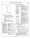
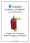
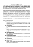
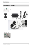
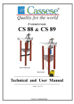
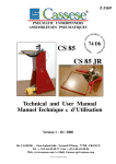
Z 6904
CS 486 XL
AIR-OPERATED ELECTRONIC UNDERPINNER
ASSEMBLEUSE ELECTRO - PNEUMATIQUE
Technical and User Manual
Manuel Technique & d’ Utilisation
Version1 - 02/2006
Cassese Communicatioon
GETTING FAMILIAR WITH YOUR CS 486 XL
Fig 1
STAPLING
BUTTON (DA)
INDICATOR INDICATOR INDICATOR
SS
V
I
REBATE
CLAMP PRESSURE
ADJUSTER
TOP PRESSER
SPEED ADJUSTER
MANOMETER
START-STOP
PRE-CLAMPING
BUTTON (PG)
BUTTON (AU)
COMPRESSED AIR
VALVE COMMAND
(KEY)BOARD
Fig 2
TOP PRESSER PLUNGER
POTENCE
BACKFENCES INCLINATION
ADJUSTERS (RI)
TOP PRESSER (Pr)
(G2) PIVOTING CLAMP
ASSEMBLY ANGLE ADJUSTER (AS)
(G1) FIXED CLAMP
(MB) SLIDING
TABLE
LOCKING
LEVER
WEDGE
DISTRIBUTOR
(BLOCK H)
REFERENCE
WORK POSITION
for explanations
(TC) SLIDING TABLE
LEFT HAND
BACKFENCE (B1)
RIGHT HAND
BACKFENCE (B2)
WIRE FOR WEDGE PUSHER
SPRING (F)
A
CS 486 XL
AIR LINE FITTINGS
Advised way of fitting :
USA
STANDARD
Male Connector
on Machine
Z 675
Z 675
quick release (Q/R)
female air connector
Z 749
Q/R US male
connector
Standard hose
connector
Z 701
Z 556
AIR SOURCE (compressor)
CONNECTING TO COMPRESSED AIR
QR
Open the access trap of the machine with the trapdoor key
supplied. See above for the air fittings supplied with machine accessories. Before connecting the compressed air
arrival hose to these fittings, screw into the quick release
female connector QR EITHER the standard hose connector
OR the US male connector. Then, connect it to an air
source of 7 bars (100 psi).
B
CS 486 XL V3
CONTENTS
Pages
IMPORTANT
- GETTING FAMILIAR WITH YOUR CS 486 XL
- CONNECTING TO COMPRESSED AIR SUPPLY
INTRODUCTION
- ACCESSORIES
- SPECIFICATIONS
- OPTIONS
- GUARANTEE
INSTALLATION
- PREPARATION
- CONNECTING TO ELECTRICITY
- CONNECTION TO POWER SUPPLY
PUTTING INTO OPERATION
A
B
1
2
2
ADJUSTMENTS
- CHOICE OF A TOP PRESSER
- USE OF THE SET OF SPACER BARS
- ADJUSTING THE SLIDING TABLE
- ADJUSTING THE INCLINATION OF THE FENCES
- ADJUSTING THE ASSEMBLY ANGLE
3
3
4
4
5
-
6
6
6
7-8
USE
MEANS OF ASSEMBLY
LOADING & CHANGING THE WEDGE CARTRIDGE
SELECTION OF STAPLING POSITIONS
SETTING & RECORDING AN ASSEMBLY PROCESS
(EXAMPLE WITH 5 WEDGE POSITIONS)
- ASSEMBLING FRAMES
MAINTENANCE
- ERROR MESSAGES E-0 / E-1
- CLEARING A WEDGE HALF ENGAGED IN WEDGE DISTRIBUTOR
- IN CASE OF HAMMER & WEDGE JAMMING + REPLACING HAMMER
- ERROR MESSAGES E2 - E3 - E4 - E5 - E6 - E7 - E8
9
10
10
11
12
INTRODUCTION
You have just bought a CS 486 XL numeric frame joining machine, so we congratulate on your sensible choice
and thank you for your trust in Cassese products.
The CS 486 XL benefits from the experience of the joining machines that brought Cassese a certain reputation.
It makes it possible to join wooden mouldings of all profiles (patent n° 7522814).
The CS 486 XL is designed to allow the operator to move all around the machine.
The joining operation is carried out by using metal wedges especially designed to perform a tight join. These
wedges come in throw-away plastic cartridges, without glue, individually lubricated and rust-protected for the
toughest challenges.
IMPORTANT : Do not use any other wedge cartridges but genuine Cassese cartridges.
(registered mark CS).
ACCESSORIES SUPPLIED WITH THE MACHINE
The CS 486 comes with a cardboard accessory box that contains:
-1 Key for machine door
-1 triangle support with 1 black rubber triangle (hard) +1 white triangle (soft)
-1 round rubber support with - according to mouldings shape and height:
2 green rubber ends for hardwood types (1 short and 1 long)
2 yellow rubber ends for soft wood types (1 short and 1 long)
-Spacer bars for small mouldings / 3 allen keys for hexagonal nuts (# 2.5 – 3 –5mm)
-1 Wedge pusher tool / 1 spare hammer (wedge driver blade) / 1 tube of grease/ 1 Ball lock,
-1 Air exhaust Silencer (muffler) / 1 quick release female air connector for the male one that is on machine / 1
quick release US male connector / 1 hose connector /
- 2 wires to connect machine to mains supply (one with standard + one with US plug).
TECHNICAL SPECIFICATIONS OF CS 486 XL
-Moulding width : Minimum 3 mm (1/8”) - maximum width : 150 mm (6”)
-Moulding height : Minimum 5 mm (3/16”) – maximum: 112 mm (4”1/2)
-Maximum width of stapling from the heel (back) of the moulding : 127mm
-Minimum dimensions of a frame : 85 mm x 85 mm visibly (3½” x 3½”)
-Wedge sizes in cartridges of 275 pieces : 5, 7, 10, 12 and 15 mm. On special order size #4 and #3 (1/8”) are
also available for assembly of slips (filets).
-Two wedge types : for soft and for hardwoods. Don’t use Hardwood wedges on softwoods.
-Machine weight : 100 kg (222 lbs)
-Dimensions : Width 48 cm (19”) x Depth 44 cm (17½”) (without optional rotating extension table) x Height
114 cm (45”)
-Power supply : Electric : 220 V - 110 V single phased, Consumption 200 W.
Pneumatic : compressed air 7 bar (100 psi). Average consumption: 5 liters / cycle.
-Air preparation : pressure reducing valve + manometer, connecting pipe, inside diameter 8 mm.
OPTIONS
-Independent rotating table, diameter 1300 mm (50¼”) to make the handling of large frames easier (frame dimensions not exceeding table diameter). Cassese Item # Z.3074.
-Set of furniture clamps to join mouldings without rebate and/or small frames. Item # Z.2763.
-Angle inserts for 6-sided frames (Item Z.3204), for 8-sided (Z.3203) or other forms on request.
-Bar code scanner system .
GUARANTEE
One year guarantee for parts and labour against manufacturing defects. Wear parts and those damaged
as a result of non appliance with the instructions of the present manual are excluded from the guarantee.
1
Wood piece
Mtc
INSTALLATION
Tc
( Connecting to compressed air: see page B)
To avoid damages due to vibrations during transit,your CS 486 XL
comes with a piece of wood located between the wedge distributor
and the sliding table Tc. To remove it, loosen Mtc (Sliding table
locking lever) and slide the table Tc backwards.
Reassemble the four feet of the machine supplied among accessories
and adjust the level of the machine to your floor so that the machine
vibrates or moves as little as possible which is the most important
reason for fast mechanical ageing of all equipment.
Wedge distributor
FITTING THE SILENCER (MUFFLER)
E
CONNECTING TO ELECTRICITY
Your machine comes with the voltage selector (S) in position
220-240 V. If your local tension is 110 V, just follow the instructions below and connect machine to 220 or 110 V single phased
grounded power socket, either with the cable supplied with
standard plug or with the one that has a US plug at its end.
Voltage
needed
Screw the silencer on machine’s frame into
nut E. Put some grease on the (threaded)
screw part of the silencer ; a full tube of
grease is delivered in the accessory box of
the machine.
S
To change machine to 110 V,
with a flat screwdriver, remove from underneath the selector S, and turn it upside down. Push it back in. The
voltage needed by machine is marked in left, upper corner of selector S.
1
Manometer
AU
PUTTING INTO OPERATION
Turn on the compressed air valve. The pressure shown on
manometer should be between 6 to 7 bars (90 to 100 p.s.i.)
If your compressor is sending out a higher pressure but the
manometer is showing less, increase the pressure at machine’s
regulator -where the air arrival is connected.
2
Compressed Air Valve
1.
Turn the red Start/Stop button (AU) (Fig.1) so that it comes up
to START (ON) position. Press on R-key (Fig.2) (RESUME)
on the keybaord to confirm the start :
1
- all indicator lights come on and off
- machine introduces the version of its program : e.g. 1-2
- wedge position P and quantity Q indicators start to blink
Pressing any key or the foot pedal, the 486 XL initialise itself and is ready to be set for wedge position P # 1.
Now all keyboard lights are fixed.
2
ADJUSTMENTS
SELECTION OF A TOP PRESSER END
Pin
1
2 top pressers comes now with your CS 486 as a standard
feature. They adapt themselves on the plunger head thanks to the
pin G and can be set up in 4 to 6 positions from the table. Pay
attention to position well the triangle : the sides of the triangle
must be parallel to stops B1 and B2 (see fig2 page A)
3
4
5
BLACK TRIANGLE PRESSER
WHITE TRIANGLE PRESSER
GREEN RUBBER TIPS
YELLOW RUBBER TIPS
HARD WOOD
SOFT WOOD
HARD WOOD 30 and 45 mm
SOFT WOOD 30 and 45 mm
Triangle top pressers are good for flat mouldings or for mouldings
presenting a flat or horizontal area to come down on. The round
rubber ends are good for complicated forms (uphill, downhill or
reverse mouldings).
6
Presser
Moulding
1 ) 54 mm
2 ) 72 mm
3 ) 90 mm
4 ) 108 mm
LOCATING THE TRIANGLE TOP PRESSER
The moulding height capacity of the new triangle top
presser support for its 4 positions :
Z15852
LOCATING THE ROUND RUBBER TOP PRESSER
A similar adjustable support for the round rubber top pressers is now available with 6 positions for its height.
As the round rubbers are available in two lengths (30mm & 45mm) and in two hardness finishes (orange for
softwoods & green for very hardwoods), the maximum height of moulding that this optional round rubber support
can work in its 6 positions are :
MAXIMUM HEIGHT FOR THE MOULDINGS
Position hole # With short round rubber With long round rubber
1
2
3
4
5
6
Z15855
20 mm
36 mm
52 mm
68 mm
84 mm
100 mm
05 mm
21 mm
37 mm
53 mm
69 mm
85 mm
USING THE SET OF SPACER BARS
Presser
In case you have to join small mouldings with
a smaller height than the fences, you must put
the spacer bars between the mouldings and the
fences to create a distance.
Fences
Moulding
INCORRECT
CORRECT
Set of spacer bars
Wedge distributor
3
ADJUSTING THE SLIDING TABLE TO THE MOULDING
1) Turn to ON the pre-clamp command button PG (Fig 1 page A) to make advance slightly the
rebate (rabbet) clamp of the machine G1 & G2 (Fig 2).
2) Make sure that the knobs of backfences inclination adjusters RI (Fig 2, page A) are at O
(zero).
3) Standing behind the machine (as seen on Fig.2, page A), put a moulding chop against left
hand fence B1.
4) Move sliding table TC (fig2 pA) forward as far as the moulding comes into contact with the
clamp G1 (fig2, pageA).
5) Tighten the sliding table blocking handle MB (fig2,pA).
6) Now you can turn the pre-clamp button PG to OFF position again.
ADJUSTMENT OF THE INCLINATION OF THE FENCES
ADJUSTMENT KNOBS ( RI ) FOR
THE INCLINATION OF THE FENCES
+
If the corner has an opening on top, turn the two
adjustment buttons (RI) an identical value to the
MINUS (-) (see above picture ) until the opening
disappears when mouldings are clamped.
0
-
If the corner has an opening underneath, turn the
same two adjustment buttons (RI) an identical
value to the PLUS (+) until the opening disappears when mouldings are clamped.
4
ADJUSTMENT OF THE ASSEMBLY ANGLE
If several cutting machines are being used in your production or if you receive
your mouldings already cut by your suppliers (chop service), the angles of the mouldings will be
slightly different from one cutting machine to the other. The wider the moulding the more visible
will be this angle difference.This is why the joining angle of your CS 486 XL can be adapted to
find precisely the cutting angle of the cutting machine.
If the corner is open towards outside, (standing behind the machine) screw in the adjustment screw AS (see picture below ) to correct the fault and check the quality of the angle
by clamping the corner again.
Open Outside
Inside
If the corner is open towards inside, unscrew the same angle adjuster AS to correct the fault
and check the quality of the corner by clamping the mouldings again.
In the event of such a result, check your cutting angle that
is actually bad because under 45°.
Have the angle of your cutting machine corrected, as it is
impossible to make a rectangle frame with angles smaller
than 90°.
( AS ) SETTING SCREW FOR
THE ASSEMBLY ANGLE
5
USE
MEANS OF ASSEMBLY
The joining is performed by using metal wedges, a Cassese invention, designed to ensure very tight corners. Five standard sizes are available : 5, 7,
10, 12 and 15 mm. On special request #3 & 4 are available for slips (filets).
They all come in throw-away cartridges that are colour-coded per size for
easy identification.
Cartridge wedges exist in two versions : NORMAL for soft and normal
timbers and HW for very hard timbers. These hardwood wedges are to be
used only on hardwoods.Your CS 486 XL is designed to use all sizes of
Cassese cartridges without having to change any parts on the machine or
having to adjust anything. For the long term performance and reliability of
your CS 486 XL, only use genuine CASSESE wedge cartridges. Beware
of bad quality copies that would cause technical problems and would age
your machine prematurely.
LOADING AND CHANGING THE WEDGE CARTRIDGE ON MACHINE
Pull the wire with ball of the wedge pusher spring F (fig.2, page A) fully out.
If there is a cartridge on machine, holding the wire pulled out, remove it by simply sliding out
the cartridge.
Holding the wire pulled out, put a new cartridge on machine and pay attention that it is
fully inserted in the wedge distributor’s window.
Release gently the wire with ball of the wedge pusher spring F.
SELECTION OF STAPLING POSITIONS
The CS 486 XL is designed to join mouldings (A) in 1 to 5 places (positions) with 1 to 5 wedges (B) in any of
those places and on a maximum width of 127mm from the heel (back) of the moulding
. In the case of several wedges in the same position, they will penetrate the wood pushing the previous
wedge(s) deeper inside. The selection of the size of wedge to be used and the number of positions depends on
the width and thickness of the moulding to be assembled.
A MINIMUM of 2 mm clearance (approx. 1/8”) above the wedges shall be respected. The harder the
wood timber, the more should be this clearance to prevent the moulding from cracking.
Advice : To get the best and tightest corners possible, make sure that wedges in each position penetrate and
pull together at least 2/3 of the height in this area.
Example: As a general rule, the joining must be carried out as close as possible to the thickest (highest)
parts of the mouldings.
minimum 2 mm (approx. 1/8”)
minimum 2 mm (approx. 1/8”)
minimum 2 mm (approx. 1/8”)
B
10mm
(3/8”wedges)
0 mm
MAXIMUM WIDTH : 127 MM
A=150mm max
6
SETTING & RECORDING AN ASSEMBLY PROCESS
EXAMPLE WITH MULTIPLE (up to 5) STAPLING POSITIONS
1 ) PREPARATION
1
2
3
4
5
0 mm
MAXIMUM WIDTH : 127 MM
Depending on the width of the mouldings, your CS 486 XL can join corners 1 to 5 stapling positions (=areas
where the wedges will be inserted). It allows the operator to set up and memorise the stapling positions just by
physically bringing the wedge distributor (Block H) to those areas. To do so :
1. Standing in the advised work position (Fig.2, page A) behind the machine, nearer to the keyboard, take the
left hand moulding chop on which for the first trials you may mark with a pencil at the bottom of the mitred
surface the positions where you want to insert wedges.
2. Put now this left moulding chop in front of the left back fence B1 (on Fig 2, page A) so that its mitred end
is in contact with the right back fence B2.
3. Turn ON the pre-clamping button PG (Fig 1, page A) and press RESET key to clear all wedge positions P
and quantities Q.
4. Now, push the sliding table TC forward with the moulding in front of it, until the moulding reaches the rebate (rabbet) clamp (G 1). And tighten the position of the table with handle MB.
• Pressing RESET key when the pre-clamp button PG is ON clears the last (whole) assembly process from
the memory of the machine,
• Pressing RESET key and the wedge position key P at the same time when the pre-clamp button PG is
OFF clears from record this memorised position,
• Pressing RESET key and the wedge quantity key Q at the same time when the pre-clamp button PG is
OFF clears the quantity and changes to 0.
Notice : When a wedge position is “empty”, i.e. either not recorded yet or cleared from memory- a dot appears
next to the number of the position.
¤ If the machine has been moved to reach its maximum or minimum capacity to outside or inside of frame, the
MINI or MAXI keys will light up and the move of the mechanism is stopped.
¤ While setting a wedge position using key
, if the machine’s wedge distributor is stopped harshly by the
sliding table (TC), because the machine reached the outside limit of the moulding, the stepping motor –counting and recording the position- may skid. In this case, move the machine back using key
and turn Preclamp button PG ON and OFF; this will enable the motor to initialise itself to record correctly the next wedge
position.
a ) First Stapling Position P1 (outside of the frame)
OUTSIDE
(
key)
INSIDE
(
key)
1
2
3
4
5
Wedge distributor’s exit slot
1
5
Although the CS 486 XL accepts the stapling positions in any order and would carry out the assembly
in the order recorded (from Position 1 to 5), it is
wise to memorise the stapling positions from outside to inside of frame, this would make the machine work faster and would create for the operator
a bigger space to bring the corner out of machine.
Move the wedge distributor (Block H) to the outside across
the moulding pressing on key
until the wedge exit slot
finds physically the position chosen (or marked with a pen).
Now specify the quantity of wedges you want to insert (or
stack on each other) by pressing repeatedly the Q–key until
the quantity chosen is there ; in example above : 5.
7
b) Second Stapling Position P 2
OUTSIDE
(
key)
INSIDE
(
key)
1
2
3
4
5
Wedge
distributor’s exit slot
Press P-key to change it to P 2. Move the wedge distributor
(Block H) across the moulding pressing on key
until the
wedge exit slot finds physically the second position chosen,
here to the inside of frame with
key. Now specify the
quantity of wedges you want to insert (or stack on each other)
by pressing repeatedly the Q–key until the quantity chosen
is there ; in example above : 3.
2
3
c) Third Stapling Position P 3
OUTSIDE
(
key)
INSIDE
(
key)
1
2
3
4
5
Wedge
distributor’s exit slot
3
3
Press P-key to change it to P 3. Move the wedge distributor
(Block H) across the moulding pressing on key
until the
wedge exit slot finds physically the third position chosen, here
to the inside of frame with
key. Now specify the quantity
of wedges you want to insert (or stack on each other) by pressing repeatedly the Q–key until the quantity chosen is there ;
in example above : 3 again.
d) Repeat the same operation as in b) or c) above for the fourth and fifth stapling positions.
At the end, once all positions and wedge quantities are recorded, turn the pre-clamp button PG to OFF. This
will make the rebate clamp come slightly back to create the space needed to bring out the corners without having to loosen the sliding table of the machine.
Notice : There is no rule or sense to be respected for the stapling positions ; P-1 can be close to the rebate
of the frame, P-2 close to the outside, then the P-3 again closer to the rebate, etc. Your 486 XL accepts
stapling positions in any order and would carry out the assembly in the order recorded (from P-1 to P-5).
See advice below. There is no obligation to record all 5 positions P-1 to P-5 ; for a small profile only one
or two positions will be sufficient ; the machine will carry out only the positions recorded.
ADVICE : There is no rule or sense to be respected for the stapling positions but, unless there is a special reason, it is advised to
memorise the stapling positions from outside to inside of frame, this would make the machine work faster and would create for the
operator a bigger space to bring the frames out of machine.In fact, sometimes this may not be possible with some too difficult profiles
which oblige the operator to start in a specific area to prevent the mouldings from rocking ; this means the Position 1 may be in the
middle, then a P-2 to the back and a P-3 for example to the inside ; the machine will carry out in the order recorded, making sure
mouldings cannot rock. TIP : your 486 XL machine accepts stapling positions with 0 (zero) no wedges and will go to that position
without inserting wedges there ; in this case the plunger will have enough time to come completely up. This ability of the machine is
very useful for some special profiles –for instance like an L – to prevent from hitting the profile because of the speed when
the machine goes from position to position to insert wedges.
8
ASSEMBLING FRAMES
Standing in the work position used as reference (Fig 2, page A), first put on the machine the left hand moulding
chop that has been used to make up the settings for the assembly process (see chapters).
Place now the right hand chop in front of the right hand back fence B2 so that they form a corner.
To join them ; there is a choice between two Assembly Modes :
a) AUTOMATIC MODE (AUTO) ; faster, more suitable for volume
production. Automatic means that the machine will carry out the whole cycle just by
pressing on the foot pedal ; will clamp mouldings at their rebate + clamp them on top
+ will go throughout all the wedge positions recorded inserting all the wedges
required.
To do so, Press AUTO-key ; the indicator lights up. Keeping mouldings well against
each other, press on the foot pedal.
RELEASE THE PEDAL ONLY AFTER THE STAPLING
CYCLE IS FINISHED AND AFTER HAVING TAKEN THE
MOUDINGS OFF THE JOINING TABLE.
b) MANUAL MODE (MAN) ; more suitable for production with profiles
changing often. Manual means that by pressing on the foot pedal, the machine will
only clamp mouldings at their rebate, so that the quality of the corner can be visually
checked before inserting wedges. Then, by pushing on the stapling button DA, the
machine will carry out all the rest of the cycle ; will clamp mouldings on top + will
go throughout all the wedge positions recorded inserting all the wedges required.
To do so, Press MAN-key ; the indicator lights up. Keeping mouldings well against
each other, press on the foot pedal. Check the quality of the corner ; if there is any
opening on top or to the inside or to the back of the corner, proceed with the adjustments proposed (see those chapters) to remedy the problem. After any adjustment,
press the foot pedal again to check the corner once more. If the quality is satisfactory,
press on stapling button DA (Fig.1 page A) to finish the assembly of the corner.
RELEASE THE PEDAL ONLY AFTER THE STAPLING
CYCLE IS FINISHED AND AFTER HAVING TAKEN THE
MOUDINGS OFF THE JOINING TABLE.
ADVICE : When you start with a new moulding or profile, join the first corner in MANUAL mode to adjust
perfectly the backfences, assembly angle etc by clamping the mouldings and seeing the result without inserting
wedges yet. Then for the following corners or frames, change to AUTOMATIC. If all these moulding chops
were cut on the same cutting machine, the machine will give you every time exactly the same result as the first
corner.
NOTICE :
While the assembly of the corner is carried out by the machine, the stapling positions and the quantity of
wedges to be inserted light up as and when proceeded.
At the end of the assembly, if more than one stapling positions has been carried out, the top presser plunger
of the machine initialises itself and goes to the first position, ready for the next corner.
If the clamp safety indicator (SS) (see Fig.1, page A) lights up, this means the machine is not clamping the
mouldings well ; (the reason may be that the table was not tightened well and went slightly backwards) if this
lights up before the start of a cycle -when pushed on foot pedal, the cycle will not be carried out, not to waste
mouldings with a bad assembly.
But if the clamp safety SS lights up while an assembly cycle is in progress –for instance if the table with
mouldings slides away progressively, while the assembly is being carried out-, the machine will continue the
cycle to the end.
9
MAINTENANCE
BEFORE ANY INTERVENTION,
UNPLUG THE POWER SUPPLY AND CLOSE THE AIR VALVE.
To prevent your machine from ageing prematurely by lack of maintenance, your Cassese 486 XL machine is
equipped with a Periodical Maintenance and easy Trouble Diagnosis System which is introduced by the machine as ERROR massages on its keyboard : the letter E lights up in the stapling positions (P) section of the
keyboard followed by a number from 0 to 8 in the wedge quantity (Q) section.
After proceeding with the maintenance required, press on RESET-key
E-0 : means PLEASE PROCEED WITH REGULAR MAINTENANCE OF WEDGE DISTRIBUTION
Your Cassese 486 XL is equipped with an internal counter to request periodical maintenance : Each time a total
of 50,000 wedges has been inserted by the machine, this message comes up.
• Remove the wedge cartridge from machine.
• With hexagonal Allen key # 3mm (accessory box) loosen the locking screw of Block H (wedge distributor).
• Remove Block H from machine and clean it with blowing air ; no need to dismantle it.
• Before putting back into machine, put a little quantity of grease (supplied with machine) into its down hole,
for the lubrication of the hammer (driver blade of the machine that pushes up the wedges).
• When putting back Block H into machine, make sure the its window is facing the cartridge side.
• And before tightening the blocking screw, check the height of Block H ; touching with your thumb, check
that it is flush with the table of the machine.
TO SWITCH OFF THE MAINTENANCE LIGHT
PUSH AT THE SAME TIME ON :
E-1 : PLEASE CHECK TOP PRESSER
•
Either the distance between the top presser and the stapling area of the moulding is more than maximum
50mm (2”) allowed ; if so please reduce the distance using a longer top presser pad.
• Or the top presser is coming down too slowly ; in this case increase the speed with the top presser speed
adjuster (Fig.1, p.A)
In these two cases a wedge may be half engaged in the wedge distributor (block H) : proceed as follows :
CLEARING OF A WEDGE HALF ENGAGED IN WEDGE DISTRIBUTOR
During assembly, one or more wedges may get stuck in the
wedge distributor (block H).
• Switch off the power and close the air valve.
• Try to remove the cartridge that is on machine.
• If it resists, use the wedge pusher tool (in accessory box)
to replace the wedge back in cartridge.
-In case of hammer and wedge jamming,
see the following section (3)
WEDGE PUSHER TOOL
6mm (1/4 ”) MAXIMUM
WEDGE
DISTRIBUTOR
( BLOCK H )
WEDGE EXIT
10
IN CASE OF HAMMER & WEDGE JAMMING
WEDGE
DISTRIBUTOR
( BLOCK H)
SCREW POSITIONS
OF BLOCK H
A
D
GF1
SLIDING TABLE
GF2
F
BLOCKING
SCREW
E
B
C
In case of the hammer (wedge driver blade) and a wedge jamming in the wedge distribution block, proceed as
follows, after having unplugged the machine from mains supply and closed the air valve.
-Remove the wedge cartridge from machine.
-With the 3mm allen key (supplied with machine), loosen (no need to remove) the blocking screw of block H
(see above).
-Remove the block H from machine and check:
1) If there is no wedge or hammer stuck inside it, put it back in machine.
2) If the hammer (like a very long wedge, approx. 8cm (3”) long) is stuck in it, we need to open the block
H to get rid of the old hammer: Use for this the smaller (2.5mm) Allen key (supplied with machine) and
remove the 2 central screws (see above GF1 & GF2) that hold the fixed (square) guide of Block H in place.
Remove the fixed guide completely to free the old hammer. If still not possible to get rid of the old hammer, remove the 4 corner screws (A-B-C-D) and open the block H. Two factory set locator pins E & F
allow the plates to be re-positioned precisely again.
Remove the old hammer. Assemble the block H back again.
PUTTING A NEW HAMMER
-Put a drop of grease (tube of grease supplied with the machine) in the bottom hole of the wedge distributor
(block H).
-Insert a new hammer into the wedge distributor from the top, with the hole of the hammer downwards.
-Re-position the wedge distributor in its housing on the machine, with the window towards the cartridge.
-If the upper end of the new hammer stays out of block H, push it fully in with a piece of wood or moulding.
-Now, connect the machine to air (must be 6-7 bars = 100 psi) and to power. Turn the start button to start and
press R-key (RESUME) on the keyboard.
-Put any of the top presser ends (triangle or round rubber) on the machine and place a piece of flat moulding or
corner on the block H, under the top presser. (The distance between the top presser and the moulding should
not exceed 50mm (2”).)
-Check that the Pre-clamp button PG is OFF ; now, keeping the RESET-key pressed, press at the same time
also on the Stapling Button (DA) ; indicator lights blink.
-Approximately, 1 second later the top presser plunger comes down and simulates a stapling ; the hammer must
have taken automatically its place in the mechanism.
AFTER ANY INCIDENT, IF THE HAMMER (driver blade) REMAINS STUCK IN WEDGE
DISTRIBUTOR (Block H), REPLACE IT BY A NEW ONE TO ELIMINATE THE RISKS OF
FURTHER JAMMINGS AND DAMAGING OTHER PARTS.
11
E-2 : START OF TRAVEL SWITCH IS DEFECT (GIVING SIGNAL CONTINUOUSLY)
This is an internal part needed by the machine to carry out its joining cycles correctly.
Solution : contact your regular supplier of Cassese products for technical help.
E-3 : END OF TRAVEL SWITCH DEFECT (GIVING SIGNAL CONTINUOUSLY)
This is another internal part needed by the machine to carry out its joining cycles correctly.
Solution : contact your regular supplier of Cassese products for technical help.
E-4 : START OF TRAVEL SWITCH DEFECT (GIVING NO SIGNAL)
Solution : contact your supplier of Cassese products for technical help.
E-5 : END OF TRAVEL SWITCH DEFECT (GIVING NO SIGNAL)
Solution : contact your supplier of Cassese products for technical help.
E-6 : YOU ARE TRYING TO START A CYCLE (i.e. FOOT PEDAL PRESSED) WHILE THE PRE-CLAMP
BUTTON PG IS STILL ON
Solution : Turn Pre-clamping Button PG (see Fig.1, page A) to OFF. Press RESET and then start the cycle
again.
E-7 : means PLEASE PROCEED WITH PREVENTIVE MAINTENANCE OF OTHER MOVING PARTS OF
THE MECHANISM
Your Cassese 486 XL is equipped with an internal counter to request periodical preventive maintenance : Every
time the machine’s mechanism (the wedge distributor and top presser) has moved a distance of 5 km (about 3
miles), the machine reminds the operator to make a short maintenance to prevent moving parts from wearing
and ageing too fast.
P
(See picture next) Top presser plunger (P) must be a little
lubricated, using a SAE 20/40 oil.
Before turning the machine on again, make the mechanism
move by hand back and forth several times to diffuse the
lubrication.
TO SWITCH OFF THE MAINTENANCE LIGHT
PUSH AT THE SAME TIME ON :
E-8 : means INSUFFICIENT OR NO AIR PRESSURE (below 6 bars = 85 psi)
Please check that the source of compressed air is supplying the pressure needed; check the arrival hoses and
make sure that the air valve of the machine is turned ON.
You get this error message also if you turn on the power before air on the machine. Once the problem is solved,
press RESET to cancel the error message.
12