1
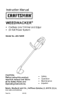
SONY
SU-27HVl y SU-32HVl 9 SU-36HVl
TV STANDlSOPORTE
DELTELEVISOR
MEUBLEDETELEVISION
INSTRUCTIONS
The SU-27HVl TV stand is designed for use only with Sony 27-inch TV sets
listed to the right.
The SU-32HVi TV stand is designed for use only with Sony 32-inch TV sets
listed to the right.
The SU-36HVl TV stand is designed for use only with Sony 364nch TV sets
listed to the right.
ha sido diseriado para ser usado
27” notados a la derecha.
ha sido diseriado para ser usado
32” notados a la derecha.
ha sido disehado para ser usado
36” notados a la derecha.
INSTRUCTIONS
Le meuble de television SU-27HVl TV est conpu pour etre utilise avec un
televiseur Sony de 68.6 cm (27 pouces).
Le meuble de television SW32HVl TV est concu pour etre utilise avec un
televiseur Sony de 82 cm (32 pouces).
Le meuble de television SU-36HVl TV est concu pour etre utilise avec un
televiseur Sony de 92 cm (36 pouces).
NOTES ON USE
l
l
KV-32FV300
KV-32HS500
KV-32HV600
KV-34DRC500
KV-34FV250
SU-36HVl:
ASSEMBLED STAND
SOPORTE ENSAMBLADO
MEUBLE ASSEMBLe
KV-36FV300
KV-36HS500
KW38DRC500
KW38FV250
NOTAS ACERCA DEL US0
Do not place the stand in a location near a
heat source, such as a radiator, or in a place
subject to direct sunlight.
Clean the stand periodically with a soft cloth.
If finger prints, food and beverage stains, etc.,
are difficult to remove, use a cloth moistened
with a mild detergent solution. Do not use a
scouring powder, abrasive pad or solvent.
WARNING / ADVERTENCIA
KW27FV300
KV-29FV300
SU-32HVl:
INSTRUCCIONES
Este soporte de televisor SU-27HVl
solamente con 10s televisores Sony de
Este soporte de televisor SU32HVl
solamente con 10s televisores Sony de
Este soporte de televisor SW36HVl
solamente con 10s televisores Sony de
SU-27HVl:
l
l
No instale el soporte de televisor en un lugar cerca
de un fuente de calor, tal coma un radiador, ni
tampoco bajo la Iuz directa del sol.
Limpie el mueble periodicamente
con un pario
suave.
Si tiene dificultad para eliminar huellas
dactilares, manchas de comida o de bebida use un
patio mojado en una solution detergente suave.
No utilice polvos o esponjas abrasivas, ni tampoco
solventes.
NOTES D’EMPLOI
l
l
N’installez
pas le meuble a proximite
d’une
source de chaleur, notamment un radiateur, ou dans
un endroit expose aux rayons directs du soleil.
Nettoyez regulierement le meuble avec un chiffon
doux. S’il est difficile de faire disparaitre
des
empreintes, des taches de boisson ou d’aliments,
par exemple, utilisez un chiffon humide et une
solution
a base de detergent
doux.
N’utili
sez pas de poudre a recurer, de tampon abrasif
ou de solvant.
/ AVERTISSEMENT
Do not use dolly.
No usar diablito.
Ne pas utiliser un diable.
Do not push/pull on legs
of TV stand.
No empujar o jalar sobre
10s pilares de el soporte
de televisor.
Do not push/pull TV set.
No empujar o jalar
televisor.
Ne pas poussemirer le
televiseur.
Ne pas pousser/tirer sur
les jambes du meuble de
television.
To avoid serious injury, do
not allow children to hang
from the television set.
To avoid injury to the user
and damage to the stand, do
not use the shelf as a step.
Para evitar lesiones
severas, no permita que 10s
nirios se cuelguen del
conjunto del televisor.
Para evitar lesiones al
usuario y daAo al mueble, no
use la repisa corn0 escalon.
Pour eviter les blessures
graves, ne laissez aucun
enfant s’accrocher au
televiseuc
0 2002 by Sony Electronics Inc.
Pour eviter que I’utilisateur
se blesse et que le meuble
soit endommage, ne I’utilisez
pas comme marchepied.
Be cautious of the base board
when walking near the stand
to prevent foot injury.
Favor de tener precaution
cuando se camine cerca del
estante para evitar accidentes.
Soyez prudent avec la
planche de base lorsque VOW
passez proche du stand afin
d’eviter une blessure aux
pieds.
PARTSLIST
LISTA DE PARTES
LISTE DESPIECES
SU-27HVl
SU-27HVl
SU-27HVl
MODEL:
MOI iL0:
-MOI ZLE:
Item
Adieu’
Article
Zlty Part
Description
Descripci6n
Description
1
No.
:ant No.parte
XC N” de pi&c :e
Top board
Repisa superior
Panneau superieur
1
Adjustable shelf
Repisa ajustable
Etagere reglable
1
,
I
t
XW2892-,1 1
-
Base board
Repisa inferior
Panneau inferieur
Side board (Left)
Panel lateral (Izquierda)
Panneau lateral (Gauche)
Side board (Ri ht)
Panel lateral ( 8 erecha)
Panneau lateral (Droit)
Side illar (Left)
Pilar gterai (Izqurerda)
Montant lateral (Gauche)
SU-32HVl
iU-32HVl
W32HVl
Part No.
No.parte
No de pi&e
-
SU-36HVl
SU-36HVl
U-36HVl
!2
ml
-
Part No.
No.parte
N” de pike
XW2881-1 1 xw2902-1
XW289: 3 1 XW2882 1 xw2903
-
1 XW284 4 1
-
1 xw2904
- --
1 XW28916 1 XW2885
-
1 xw2907
1 XW289! 5 1 XW2886
-
1 XW2906
-
1 XW28916 1 XW2887
-
1 xw2909
-
1 XW289 7 1 XW2888
-
1 XW2908
-
Front pillar (Left)
Pilar frontal (I2 uierda)
Montant avant 7.Gauche)
1 XW29Ol 0 1
1
Front pillar (Right)
Pilar frontal (Derecha)
Montant avant (Droit)
1 XW289! 9 1
Inner board (Left)
Soporte interior (Izquierda)
Panneau interieur (Gauche)
1 XW291l 6 1
Inner board (Right)
Soporte interior (Derecha)
Panneau interieur (Droit)
1
Back panel
Panel trasero
Panneau arriere
1 xw290 1 1
Side illar (Right)
Pilar fatera (Derecha)
Montant lateral (Droit)
XW2889
XW2890
1
-
MO018
4+
Part No.
Uo.parte
U” de pi&cc
ItYr I‘art No.
t r4o.parte
I2 ! rPde pike
2
-
MO221
>
4
-
MOO19
2
MO223
ItY
an
tti
Part No.
No.parte
N‘ de pike
MO220
2 MO222
-
t
-
MOO19
4 MOO19
-
>
MO223
2 MO223
-
PO178
1
-
-
Magnet
Receptor
Aimant
1 PO178
I
-
-
PO178
magnetic0
2
PO068
)
PO068
PO068
PO264
PO264
MO21 9
MO21 9
PO010
PO010
-
2
2
XW2891
1
-
XW2918
2
PO264
)
MO219
>
1
-
xw2917
Hinge cap (Left)
Tapa de bisagra (Izqurerda)
Couvre-charm&e
(Gauche)
1
xw2912
(pie-installed)
(pre-&ala&)
(pm-rnstallee)
1 PO265
’
Qsil
2
GO354
1 MOO18
-
1
MOO18
(pm-rnstalled)
(pm-instalada)
(pm-rnstallse)
8
so035
4 SO064
4
-
SO064
4 SO064
- --
0 BOO77
I(
BOO77
IO BOO77
Spreading bolt
Esprea moldeada
Boulon d’ecartement
-
-
2 MO202
2
-
MO202
2
MO202
3 so030
9
-
so030
9
-
so030
Screw% M4x16
Tornillo%M4x16
Vis % M4x16
1 so122
1
-
so1 22
1 so1 22
-
Screw $ M8x8
Tornillo %M8x8
Vis % M&8
S SO063
6
-
SO063
8
SO063
4 SO006
4
-
SO006
4
SO006
0 BOO56
IC BOO56
Cam casting (preinstalled)
Leva moldeada (pre-instalada)
Came (prs-installee)
IO BOO56
-
>
Washer
Arandela
Rondelle
1 PO266
Qa
~
0-D
1
PO265
1
PO267
PO266
1
PO268
-
GO353
8
PO010
-
Hinge cap (Right)
Tapa de bisagra (Derecha)
Couvre-charniere
(Drort)
2
-
I
SU-36HVl
SU-36HVl
I-36HVl
TV clip holder
Hevilla de plastrco
Porte-pince
du televrseur
Dowel 08x30
Espiga 08x30
Goujon 08x30
3 so035
4
Metal pin
Perno metalico
Broche metallique
xw2910
Confirmat screw (Hex.)
Tornillo Confirmat
Vis (Hexagonale 8.t&e creuse)
Screw%M3x14
Tornillo %M3x14
Vis%M3x14
g$%;;ue=
SU-32HVl
SU-32HVl
Sl I-32HVl
-
XW291! 5 1
1
-&3X@
Door frame
Marco de la puerta
Cadre de Porte
-r
-
-
&z&T”~
Screw% #6x5/8”
Tornillo%#‘6xs/8”
Vis% #6x5/8”
0
0
xw2911
-
ml
Item
Description
4rticulf Descripcih
Micle Description
-
2 GO355
Strike plate
Placa receptora
G&he
-<
2xi
-
-
Glass door
Puerfa de vidrio
Porte vitree
Screw% M4x30
Tornillo% M4x30
Vis% M4x30
&
SU-27HVl
SU-27HVl
I-27HVl
MODEL:
MOt :Lo:
-MOC :LE:
I
0
-
-
8
woo92
3
-
woo92
8
-
2
-
PO189
>
PO189
2
-
PO189
REPLACEMENT
PARTS INFORMATION
(TV stand parts only)
NOTES ON ASSEMBLY
. You will need a medium size Phillips head screwdriver.
. Assemble the stand only by the method shown in this
instruction sheet.
. Assemble the stand near the location where the stand will be used.
. The circled letters in the illustrations are the same as those in the “PARTS LIST”.
For easier assembly, line up the parts in the order they will be required.
. Retain this manual for future reference.
NOTAS ACERCA DEL MONTAJE
Review parts list before assembly.
Please examine all packing material before discarding
If any parts are missing or damaged, identify and refer to
the instructions on the warrantv Daae.
To purchase replacement
number listed below.
l-619-661-6136
INFORMACION
. Usted necesitara un desarmador mediano de cruz.
. Ensamble el sopotte de televisor siguiendo unicamente el metodo mostrado en
estas instrucciones.
. Haga el montaje cerca del lugar donde se usara.
. Las letras encerradas en circulo en las ilustraciones, son las mismas letras en la
“LISTA DE PARTES”. Para facilitar et montaje alinie las partes en el orden en
que seran usadas.
. Conserve este manual para referencia futura
for residents of the United States.
PARA PARTES DE REEMPLAZO
(Solo para soporte de TV)
Revise la lista de partes antes de ensamblar.
Por favor examine el contenido del empaque antes de tirarlo.
Si alguna parte falta o esta datiada, identifiquela
instrucciones en la hoia de aarantia.
Para ordenar partes de reemplazo,
y siga las
llame al tel.
I-61 g-661-61 36 para residentes de 10s Estados Unidos.
INFORMATIONS
NOTES D’ASSEMBLAGE
parts only, call the telephone
SUR LES PI&ES
DE RECHANGE
(Concernent uniquement le meuble de television)
.
.
.
.
Vous aurez besoin d’un tournevis cruciforme de taille moyenne.
Assemblez le meuble uniquement selon la methode d&rite dans ce mode d’emploi.
Assemblez le meuble pres de I’endroit ou il sera utilise.
Les lettres entoureesdans les schemas sont les memes que celles figurant dans la
liste (c LISTE DES PIECES )). Afin de faciliter I’assemblage, alignez les pieces par
ordre de montage.
. Gardez ce manuel pour reference ulterieure.
Verifiez toutes les pieces avant I’assemblage.
Veuillez examiner tous les emballages avant de les jeter.
Si certaines pieces sont manquantes ou defectueuses,
reportez-vous aux instructions de la paae de aarantie.
Pour I’achat de pieces de rechange uniquement, appelez
le numero ci-dessous.
l-619-661-6136
NOTE: Cam casts are pre-installed into wood pieces.
NOTA: Las “levas moldeadas” estan preinstaladas en las piezas de madera.
NOTE: Les tames sont pre-installees dans les pieces en bois.
II
pour les habitants des ctats-Unis.
Arrow direction shows front.
La direction de la flecha indica el frente.
La direction de la f&he indique le devant.
INCORRECT
INCORRECT0
CORRECT
0x2
Insert the spreading bolt by hand into the hole.
fnserte la esprea moldeada a mano en el agujero.
lntroduisez le boulon d’ecartement dans le trou a la main.
REPISA INFERIOR
PANNEAU INFliRIEUR
CAUTION:
DO NOT ATTACH THE SPREADING
PRECAUCION:
ATTENTION:
NO AJUSTE
BOLT TO ANY BOARD OR PANEL WITH A HAMMER.
LA ESPREA MOLDEADAA
NE FIXEZ PAS LE BOULON
CUALQUIERA
D’ECARTEMENT
REPISA 0 PANEL CON UN MARTILLO.
A UN PANNEAU
3
OU UNE PLANCHE
AVEC UN MARTEAU.
See Fig. 1 & 2 on this page.
Vea las ilustraciones
Reportez-vous
1 y 2 en esta pdgina.
aux Fig. 1 et 2 de cette page.
Fig. 1
Spreading
bolt hole
Agujero para
la esnrea moldeada
/
Orifice du boulon
d’ecartement
NOTE: The arrow mark on the cam casts
must point towards the edge of board.
IFig.
2
NOTA: La flecha serialada en la “leva moldeada”
debe apuntar hacia la orilla de la tabla.
NOTE: La f&he sur les tames doit etre pointee
vers le bord du panneau
Turn clockwise.
--
.
Dele vueltas en el
sentido de las
manecillas del reloj.
Tournez dans le
sens des aiguilles.
0c
x4
See Fig. 1 & 2 on page 4.
Vea las ilustraciones 1 y 2 en la pdgina 4.
Reportez-vous aux Fig. 1 et 2 de la page 4.
When attaching top board to side and inner board do
not tighten the screws. For proper alignment, hold
the panels in place, insert screws in all the holes,
then tighten alternating sides.
Cuando una el tablero superior al tablero lateral y al
tablero interior no apriete 10s tornillos. Para obtener
una alineacion apropiada, sostenga 10s paneles en el
lugar, inserte 10s tornillos en todos 10s agujeros, y
luego apriete 10s tornillos alternando lados.
Ne serrez pas les vis lors de la fixation du panneau
superieur au panneau interieur lateral. Pour un
alignement correct, maintenez le panneau en place,
introduisez les vis dans tous les trous et serrez en
alternant de c&es.
El
722
_:
-..
0
9
See Fig. 1 & 2 on page 4.
Vea las ilustraciones
eportez-vous
1 y 2 en la phgina 4.
aux Fig. 1 et 2 de la page 4.
I
WHEN INSTALLING ITEM @ a@, INSERT
BOTTOM END FIRST THEN PIVOT TOP END WITH
SPREADING BOLT@ INTO HOLE.
CUANDO INSTALE LOS ARTiCULOS @ Y @ ,
INSERTE PRIMER0 EL EXTREMO INFERIOR;
LUEGO, GIRE EL EXTREMO SUPERIOR CON LAS
ESPREAS MOLDEADAS @ EN ELAGUJERO.
~0~s DE LA POSE DES ELEMENTS @ ET @,
INTRODUISEZ L’EXTRcMITe INFCRIEURE EN
PREMIER ET FAITES ENSUITE PIVOTER
CEXTRliMIT6 SUPiRlEURE AVEC LE BOULON
D’CCARTEMENT 0 DANS LE TROUS.
Screw magnet into plastic receptacle and hand tighten.
Atornille el iman en el receptaculo plastico y aprietelo a
mano.
Vissez I’aimant dans le receptacle en plastique et serrez
a la main.
Choose the appropriate holes for shelf adjustment
depending on the components to be installed.
Escoja 10s agujeros adecuados para ajustar la repisa
dependiente a 10s componentes que se instalaran.
Le choix des trous appropries au reglage de l’etagere
depend des appareils a installer.
6
b
P x2
Tighten these 2 screws first.
Apriete estos 2 tornillos primero.
Snrrnz d’abord ces 2 vis.
m
T
(pre-installed)
(pre-instalada)
(p&install&?)
P
INSERT DOOR FRAME OVER METAL PIN
BEFORE INSTALLING HINGE HOLDER.
INSERTE EL MARCO DE LA PUERTA SOBRE
EL PERNO METALICO ANTES DE INSTALAR
EL SOPORTE DE LA BISAGRA.
IhlTDnnl IISEZ LE CADRE DE LA PORTE
SUR LA BRlOCHE MeTALLIQUE AVANT DE
POSER LE DnRTF-CHARNICRE.
, v, , , L -. ., . ., .._ .I,”
I
I
l”Y”lC
7
DIMENSIONS OF GLASS DOOR
DIMENSIONES DE LA PUERTA DE,VIDRIO
DIMENSIONS DE LA PORTE VITREE
DISTANCE
DISTANCIA
DISTANCE
SU27HVl
mm
H
B
SU-32HVl
mm
SU36HVl
mm
(Inch)
(inch)
(Inch)
290.8
350.2
(13 *%a)
443
400
(15 314)
398.3
(15 ‘l/16)
(11 7/16)
480.9
(18
15/16)
(17
7/i6)
Tempered Glass I Vidrio Templado
I Verre Tremp6
The glass panels in this stand are made of tempered glass. Although it is more shock-resistant than ordinary glass, tempered
glass may shatter if it receives a sudden shock. Be careful not to drop or scratch the glass.
I
Iml
La puerta de vidrio de este soporte de televisor esta hecha de vidrio templado. Aunque es mas resistente a impactos que
el vidrio ordinario, puede fracturarse si recibe un golpe repentino. Tenga cuidado en no dejar caer o en rayar el vidrio.
Les panneaux en verre de ce meuble sont en verre trempe. Bien qu’il rosiste mieux aux chocs que le verre ordinaire, le
verre trempe peut se fissurer s’il est soumis a un choc brutal. Veillez a ne pas le laissar tomber et a ne pas le griffer.
SU-36HVl
0
E x2
0E
x2
LA PUERTA
IZQUIERDA DE
PORTE GAUCHE
PORTE GAUCHE
FOLLOW
THE SAME INSTRUCTIONS
TO INSTALL THE RIGHT DOOR
SIGA LAS MISMAS INSTRUCCIONES
PARA INSTALAR LA PUERTA DERECHA DE VIDRIO
SUIVEZ LES MEMES INSTRUCTIONS
POUR INSTALLER LA PORTE DROITE.
CAUTION: FAILURE TO SECURELY FASTEN THE DOOR WHEN TIGHTENING THE HINGE SCREWS COULD RESULT IN INJURY.
PRECAUCION: FALLAR AL SUJETAR LA PUERTA MIENTRAS SE APRIETAN LOS TORNILLOS DE LA BISAGRA PUEDE RESULTAR EN UNA LESION.
Al-EN-RON: IL EXISTE UN RISQUE DE BLESSURE LORS DU SERRAGE DES VIS DES CHARNIERES SI LA PORTE NEST PAS CORRECTEMENTATTACHEE.
DOOR ADJUSTMENT
I AJUSTE DE LAS PUERTAS DE VIDRIO I AJUSTE DE LAS PUERTAS DE VIDRIO
Loosen the screws and adjust the glass door positions if the door clearance is not adequate.
Afloje 10s tornillos y ajuste las posicicnes de las puertas si las aperturas de las puertas no estan adequadas.
Desserrez les vis et ajustez la position de la potte en verre si I’espace avec la Porte n’est pas adequat.
CAUTION / PRECAUCION
/ATTENTION
PLEASE INSTALL GLASS DOORS AFTER THE STAND IS SET AT THE FINAL LOCATION.
REMOVE GLASS DOORS PRIOR TO MOVING THE STAND.
FAVOR DE INSTALAR LAS PUERTAS DE VIDRIO DESPUES DE COLOCAR EL MUEBLE EN SU POSICION FINAL.
QUITE LAS PUERTAS DE VIDRIO ANTES DE MOVER EL MUEBLE.
INSl?REZ LES PORTES EN VERRE UNE FOIS LE MEUBLE INSTALLk DANS SON EMPLACEMENT
RETIREZ LES PORTES EN VERRE AVANT DE DtiPLACER LE MEUBLE.
8
DEFINITIF.
INSTALLING THE TV
INSTALACbN
DEL TELEVISOR
INSTALLATION DU TgLiVISEUR
SU-27HVl:
KV-27FV300
KV-29FV300
SU-32HVl:
KV-32FV300
KV-32HS500
KV-32HV600
KV-34DRC500
KV-34FV250
PROTECT EDGES WHEN
SETTING TV ONTO STAND.
SU-36HVl:
PROTEJA LOS BORDES CUANDO
COLOCA LATV SOBRE EL
SOPORTE.
KV-36FV300
KV-36HS500
KV-38DRC500
KV-38FV250
NOTE: FOLLOWING
/131
NOTA: SIGUIENTE
NOTE: L’ETAPE
q
PROTEGEZ LES BORDS LORS
DE LA POSE DU TELEVISEUR
SUR LE MEUBLE.
STEP
PASO
q WILL INCREASE
q INCREMENTARA
Cl-DESSOUS
RENFORCE
THE STABILITY
LA ESTABILIDAD
LA STABILITE
1
OF THE FlNALTELEVISION/STAND
DEL COMBINADO
DE L’ENSEMBLE
UNIT.
TELEVISOR/SOPORTE.
TELEVISEUR/MEUBLE.
Attach the TV clip holder to the
TV with the screw. Then, insert
the buckle into the slot on the TV
clip holder.
Ajuste la hevilla de plastic0 al
televisor con el tornillo. Luego,
inserte el cinturon de seguridad
en la ranura de la parte posterior
de la hevilla de plastico.
Fixez le Porte-pince du
televiseur au televiseur a I’aide
de la v/s. lnserez ensuite la
boucle dans la fente du portepince du televiseur.
2
Tighten the strap by
pulling in downward direction.
Apriete la correa jalando
hacia abajo.
Serrez la courroie en
tirant vers le bas.
Unit
: mm (inches)
Unidad : mm (pulgadas)
Unite : mm (pouces)
DIMENSIONS
DIMENSIONES
DIMENSIONS
-
-
SU-27HVl
Weight : Approx. 27 Kg (59.5 Ibs.)
Peso : Aprox. 27 Kg (59.5 Ibs.)
Poids : Environ 27 Kg (59.5 Ibs.)
A
B
C
1 814
1 629.7
502.2
D
487.9
19 7i32
450.5
405.7
15
E
F
507.1
N/A
19 3'132
469.7
479.0
18 ‘lz
18 27/s2
424.9
434.4
16 %a
17 3132
G
476.9
18 2%
594.5
23
I3132
640.4
25
7/32
H
448.1
17
561 .O
22
3132
602.0
23
"116
15 2%
399.0
15
23/32
399.0
15 =/ss
710.4
27
31/32
739.5
29 '18
712.9
28 ‘IIS
742.0
29 7/32
I
399.0
J
581.4
K
583.9
25132
25132
N/A
2'132
22
7/a
23
1 746.5
547.4
1
29 3/a
21 Vi6
17
314
1 843.3
632.5
1 33 3/16 1
24 28132
3'i32
L
303.5
ii
15/16
283.3
11 5132
262.9
10 "132
M
273.5
10
25/32
253.3
9 31/32
232.9
9 5132
N
0
243.5
213.5
9
8
‘9132
‘3/32
223.3
193.3
8 26132
7 5/a
202.9
172.9
6
8
13/i6
P
183.5
7
7132
163.3
6
7/16
142.9
5 5/a
Q
153.5
6
'132
133.3
5
'I4
112.9
4 7/16
314
128.3
5
'116
97.7
15/16
158.3
6
7/32
127.7
5
'132
188.3
7
‘3132
157.7
6
7/32
218.3
8
‘9132
187.7
7
318
248.3
9 2%
217.7
8
g/i6
278.3
10
247.7
9
R
146.0
S
176.0
T
206.0
U
SU-32HVl
Weight : Approx. 32.9 Kg (72.5 Ibs.)
Peso : Aprox. 32.9 Kg (72.5 tbs.)
Poids : Environ 32.9 Kg (72.5 Ibs.)
I24
19
236.0
266.0
5
6
8
‘la
9 9132
10
15/32
3'/32
3 27/s2
314
SU-36HVl
Weight : Approx. 37.6 Kg (83 Ibs.)
Peso : Aprox. 37.6 Kg (83 Ibs.)
Poids : Environ 37.6 Kg (83 Ibs.)
CARRYING CA PACITY OF EACH SHELF
DE CADA REPISA
RESISTENCIA
CAPACITt
DE RESISTANCE DES tTAGli
SONY ELECTRONICS
SONY ELECTRONICS
SONY ELECTRONICS
INC. PRINTED IN USA
INC. IMPRESO EN EUA
INC. IMPRIME AUX ETATS-UNIS
RES
Design and specifications subject to change without notice.
Diserio y especificaciones sujetos a cambio sin previo aviso.
Conception et caracteristiques susceptibles d’etre modifiees sans avis prealable.
10
SONY;
FOR RESIDENTS OF CANADA
POUR LES HABITANTS DU CANADA
PARA RESIDENTES DE CANADIENSES
SU-27HVl
SU-32HVl
SU-36HVl
Please examine all packaging materials before discarding.
If any parts are missing or damaged,
please review the parts list found in the assembly manual,
identify the missing or damaged part,
and call the Sony customer service center at
I-877-779-9929.
Veuillez examiner tout I’emballage avant de le jeter.
Si des pieces sont manquantes ou endommagees,
veuillez v&ifier les pi&es qui se trouvent dans le manuel de montage,
identifier les pieces manquantes ou endommagees,
et appeler le service client de Sony au num&o:
I-877-779-9929.
Por favor examine todo el material de empaque antes de tirarlo.
Si cualquier parte resulta faltante o estti daAada,
por favor revise la lista de partes que se encuentra
en el manual de ensamble, identifique la parte dafiada o faltante,
y llame al centro servicio al cliente de Sony al
I-877-779-9929.
SONY@
SU-27HVl
SU-32HVl
SU-36HVl
FOR RESIDENTS OF THE UNITED STATES
PARA RESIDENTES DE LOS ESTADOS UNIDOS
POUR LES HABITANTS DES ETATS-UNIS
Sony Electronics Inc. (“Sony”) warrants this product against defects in material or workmanship. subject to
any conditions set forth as follows:
1. This warranty is expressly limited to the replacement of Sony TV Stand parts and components.
2. For a period of 30 days from the date of purchase, Sony will supply parts that are determined to be
defective or missing, at no charge. to the origmal purchaser. After the warranty period. you will be
charged for all orders.
This warranty does not cover damages which occur in shipment or failures due to nctb of God. accident.
misuse, abuse, negligence, faulty installation. misapplication, setup. improper maintenance. commercial use.
or modification of. or to any part of the product. This warranty does not cover Products sold AS IS or WITH
ALL FAULTS. This warranty is valid only in the United States.
Proof of purchase in the form of a bill of sale or receipted invoice. which is evidence that the umt is within the
warranty period, must be presented to obtain the replacement parts.
REPLACEMENT PARTS AS PROVIDED UNDER THIS WARRANTY ARE THE EXCLUSIVE REMEDY OF THE CONSUMER. SONY SHALL NOT BE LIABLE FOR ANY INCIDENTAL OR CONSEQUENTIAL DAMAGES FOR BREACH OF ANY EXPRESS OR IMPLIED WARRANTY ON THIS PRODUCT. EXCEPT TO THE EXTENT PROHIBITED BY APPLICABLE LAW. ANY IMPLIED WARRANTY
OF MERCHANTABILITY
OR FITNESS FOR A PARTICULAR PURPOSE ON THIS PRODUCT IS LIMITED IN DURATION TO THE DURATION OF THIS WARRANTY.
Some states do not allow the exclusion or limitation of incidental or consequential damages. or allow limitations on how long an implied warranty lasts. so the above limitations or exclusions may not apply to you. This
warranty gives you specific legal rights, and you may have other rights which vary from state to state.
In order to obtain replacement parts. you must provide a PROOF OF PURCHASE and complete the information on this warranty card. Fax or mail these to:
Tocabi America Corp.
755 Main Street, Cbula Vista, CA 91911
Fax No.: (619) 656-8181
www.tocabi.com
game:
iddress:
zity:
State: ~
Zip Code: ~-
Phone: -
Ylodel:
Part No.
Quantity
Description
Reason
__~~-
Printed in USA
4-064-678-01
12