1
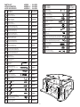
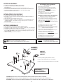
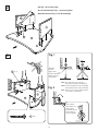
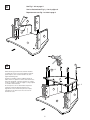
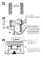
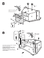
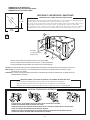
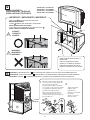
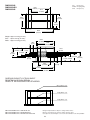
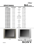
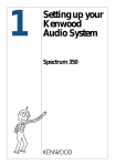
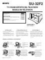
SU-32F2
TV STAND/SOPORTE DEL TELEVISOR/
MEUBLE DE TÉLÉVISION
SU-32F2:
INSTRUCTIONS
The SU-32F2 TV stand is designed for use only with Sony 32-inch TV set
listed to the right.
INSTRUCCIONES
Este soporte del televisor SU-32F2 ha sido diseñado para ser usado
solamente con el televisor Sony de 82 cm (32 pulg.) notado a la derecha.
INSTRUCTIONS
Le meuble de télévision SU-32F2 est conçu pour être utilisé avec un
téléviseur Sony de 82 cm (32 pouces) indiqué à droite.
KV-32FS120
KV-32FS210
KV-32FS320
KV-32FV300
KV-32FV310
KV-32HS500
KV-32HS510
KV-32HV600
ASSEMBLED STAND
SOPORTE ENSAMBLADO
MEUBLE ASSEMBLÉ
NOTES ON USE
●
●
Do not place the stand in a location near a
heat source, such as a radiator, or in a place
subject to direct sunlight.
Clean the stand periodically with a soft cloth.
If finger prints, food and beverage stains, etc.,
are difficult to remove, use a cloth moistened
with a mild detergent solution. Do not use a
scouring powder, abrasive pad or solvent.
NOTES D’EMPLOI
NOTAS ACERCA DEL USO
●
●
No instale el soporte de televisor en un lugar cerca
de una fuente de calor, tal como un radiador, ni
tampoco bajo la luz directa del sol.
Limpie el mueble periodicamente con un paño
suave. Si tiene dificultad para eliminar huellas
dactilares, manchas de comida o de bebida use un
paño mojado en una solución detergente suave.
No utilice polvos o esponjas abrasivas, ni tampoco
solventes.
●
●
N’installez pas le meuble à proximité d’une
source de chaleur, notamment un radiateur, ou dans
un endroit exposé aux rayons directs du soleil.
Nettoyez régulièrement le meuble avec un chiffon
doux. S’il est diffi cile de faire d i s p a r a î t r e d e s
empreintes, des taches de boisson ou d’aliments,
par exem ple, utilisez un chiffon humide et u n e
solution à base de détergent d o u x .
N’utili
sez pas de poudre à récurer, de tampon abrasif
ou de solvant.
WARNING / ADVERTENCIA / AVERTISSEMENT
Do not use dolly.
No usar diablito.
Ne pas utiliser un diable.
Do not push/pull on legs
of TV stand.
No empujar o jalar sobre
los pilares de el soporte
de televisor.
Do not push/pull TV set.
No empujar o jalar el
televisor.
Ne pas pousser/tirer le
téléviseur.
Ne pas pousser/tirer sur
les jambes du meuble de
télévision.
To avoid serious injury, do
not allow children to hang
from the television set.
To avoid injury to the user
and damage to the stand, do
not use the shelf as a step.
Be cautious of the base board
when walking near the stand
to prevent foot injury.
Para evitar lesiones
severas, no permita que
los niños se cuelguen del
conjunto del televisor.
Para evitar lesiones al
usuario y daño al mueble, no
use la repisa como escalon.
Favor de tener precaución
cuando se camine cerca del
estante para evitar accidentes.
Pour éviter que l’utilisateur
se blesse et que le meuble
soit endommagé, ne l’utilisez
pas comme marchepied.
Soyez prudent avec la planche
de base lorsque vous passez
près du meubleafin d’éviter
une blessure aux pieds.
Pour éviter les blessures
graves, ne laissez aucun
enfant s’accrocher au
téléviseur.
© 2004 by Sony Electronics Inc.
1
PARTS LIST
LISTA DE PARTES
LISTE DES PIÈCES
Item Description
Artículo Descripción
Réf.
Description
1
Top board
Repisa superior
Panneau supérieur
2
Adjustable shelf
Repisa ajustable
Etagère réglable
3
Base board
Repisa inferior
Panneau inférieur
4
Side board (Left)
Pánel lateral (Izquierdo)
Panneau latéral (Gauche)
5
Side board (Right)
Pánel lateral (Derecho)
Panneau latéral (Droit)
6
Side pillar (Left)
Pilar lateral (Izquierdo)
Montant latéral (Gauche)
7
Side pillar (Right)
Pilar lateral (Derecho)
Montant latéral (Droit)
8
Front pillar (Left)
Pilar frontal (Izquierdo)
Montant avant (Gauche)
9
Front pillar (Right)
Pilar frontal (Derecho)
Montant avant (Droit)
MODEL : SU-32F2
MODELO : SU-32F2
MODÈLE : SU-32F2
Qty
Cant.
Qté
1
1
1
1
1
1
1
1
1
Part No.
Nro. de parte
N° de pièce
4
M0019
M
Metal pin
Perno metálico
Broche métallique
2
M0223
N
TV clip holder
Hevilla de plástico
Porte-pince du téléviseur
1
P0178
O
Magnet
Receptor magnético
Aimant
2
P0068
P
Stop guide
Topes guía
Butoir
2
P0264
Q
Hinge holder
Soporte de bisagra
Porte-charnière
2
M0219
R
Bushing
Buje
Coussinet
2
P0010
S
Hinge cap (Left) (pre-installed)
Tapa de bisagra (Izquierda) (pre-instalada)
Couvre-charnière (Gauche) (pré-installé)
1
P0265
T
Hinge cap (Right) (pre-installed)
Tapa de bisagra (Derecha) (pre-instalada)
Couvre-charnière (Droit) (pré-installé)
1
P0266
U
Dowel Ø8x30
Espiga Ø8x30
Goujon Ø8x30
4
W0092
V
Washer
Rondana
Rondelle
2
P0189
W
Connecting bolt
Perno de conexion
Boulon d’assemblage
2
B0005
XW3716
XW3122
XW3121
XW3662
XW3661
P0322
P0323
11
Inner board (Right)
Soporte interior (Derecho)
Panneau intérieur (Droit)
1
XW3123
12
Back panel
Pánel trasero
Panneau arrière
1
XW2891
13
Glass door
Puerta de vidrio
Porte vitrée
2
G0369
A
Allen wrench
Llave Allen
Clé Allen
1
M0018
B
Confirmat screw (Hex.)
Tornillo Confirmat
Vis (Hexagonale à tête creuse)
8
S0035
C
Screw M4x35
Tornillo M4x35
Vis M4x35
4
S0156
D
Spreading bolt
Esprea moldeada
Boulon d'écartement
8
B0077
E
Strike plate
Placa receptora
Gâche
2
M0202
F
Screw #6x5/8"
Tornillo #6x5/8"
Vis #6x5/8"
9
S0030
G
Screw M4x16
Tornillo M4x16
Vis M4x16
1
H
Screw M8x8
Tornillo M8x8
Vis M8x8
6
I
Screw M3x14
Tornillo M3x14
Vis M3x14
J
Cam casting (pre-installed)
Leva moldeada (pre-instalada)
Came (pré-installée)
K
Door frame
Marco de la puerta
Cadre de porte
Part No.
Nro. de parte
N° de pièce
Metal tube
Tubo metálico
Tube métallique
XW2882
10
Qty
Cant.
Qté
L
XW3713
Inner board (Left)
Soporte interior (Izquierdo)
Panneau intérieur (Gauche)
1
Item Description
Artículo Descripción
Réf.
Description
XW3124
1
6
10
12
4
8
2
S0122
K
S0063
11
13
13
4
S0006
3
10 B0056
2
5
M0220
2
7
K
9
NOTES ON ASSEMBLY
●
●
●
●
●
REPLACEMENT PARTS INFORMATION
(TV stand parts only)
You will need a medium size Phillips head screwdriver.
Assemble the stand only by the method shown in this
instruction sheet.
Assemble the stand near the location where the stand will be used.
The circled letters in the illustrations are the same as those in the "PARTS LIST".
For easier assembly, line up the parts in the order they will be required.
Retain this manual for future reference.
Review parts list before assembly.
Please examine all packing material before discarding.
If any parts are missing or damaged, identify and refer to
the instructions on the warranty page.
To purchase replacement parts only, call the telephone
number listed below.
1-619-661-6136 for residents of the United States.
1-877-779-9929 for residents of Canada.
NOTAS ACERCA DEL MONTAJE
●
●
●
●
●
INFORMACION SOBRE PARTES DE REEMPLAZO
Usted necesitará un desarmador mediano de cruz.
Ensamble el soporte de televisor siguiendo únicamente el método mostrado en
estas instrucciones.
Haga el montaje cerca del lugar donde se usará.
Las letras encerradas en círculo en las ilustraciones, son las mismas letras en la
"LISTA DE PARTES". Para facilitar el montaje alinie las partes en el orden en
que serán usadas.
Conserve este manual para referencia futura
(Partes para el soporte del televisor únicamente)
Revise la lista de partes antes de ensamblar.
Por favor examine el material del empaque antes de tirarlo.
Si alguna parte falta o está dañada, identifíquela y siga las
instrucciones en la hoja de garantía.
Para ordenar partes de reemplazo, llame al teléfono indicado
a continuación.
1-619-661-6136 para residentes de los Estados Unidos.
NOTES D’ASSEMBLAGE
●
●
●
●
●
1-877-779-9929 para residentes de Canadá.
Vous aurez besoin d’un tournevis cruciforme de taille moyenne.
Assemblez le meuble uniquement selon la méthode décrite dans ce mode d’emploi.
Assemblez le meuble près de l’endroit où il sera utilisé.
Les lettres entourées dans les schémas sont les mêmes que celles figurant dans la
liste « LISTE DES PIÈCES ». Afin de faciliter l’assemblage, alignez les pièces par
ordre de montage.
Gardez ce manuel pour référence ultérieure.
INFORMATIONS SUR LES PIÈCES DE RECHANGE
(meuble de télévision uniquement)
Vérifier toutes les pièces avant l’assemblage.
Inspecter tous les matériaux d’emballage avant de les jeter.
Si des pièces sont absentes ou défectueuses,
consulter les instructions de la page de garantie.
Pour l’achat de pièces de rechange uniquement, composer le
numéro ci-dessous.
1-619-661-6136 pour les résidents des États-Unis.
1-877-779-9929 pour les résidents du Canada.
Arrow direction shows front.
La dirección de la flecha indica el frente.
La direction de la flèche indique l’avant.
NOTE: Cam casts are pre-installed into wood pieces.
NOTA: Las "levas moldeadas" estan pre-instaladas en las piezas de madera.
NOTE: Les cames sont pré-installées dans les pièces en bois.
1
INCORRECT
INCORRECTO
INCORRECT
CORRECT
CORRECTO
CORRECT
U x 2
D x 8
Insert the spreading bolt by hand into the hole.
Inserte la esprea moldeada a mano en el agujero.
Introduisez le boulon d’écartement dans le trou à la main.
R x 2
3
BASE BOARD
REPISA INFERIOR
PANNEAU INFÉRIEUR
CAUTION: DO NOT ATTACH THE SPREADING BOLT TO ANY BOARD OR PANEL WITH A HAMMER.
PRECAUCION: NO AJUSTE LA ESPREA MOLDEADA A CUALQUIERA REPISA O PANEL CON UN MARTILLO.
ATTENTION: NE FIXEZ PAS LE BOULON D’ÉCARTEMENT À UN PANNEAU OU UNE PLANCHE AVEC UN MARTEAU.
3
2
See Fig. 1 & 2 on this page.
Vea las ilustraciones Fig. 1 y 2 en esta página.
Reportez-vous aux Fig. 1 et 2 de cette page.
4
5
A
3
3
Fig. 1
Spreading
bolt hole
C x 4
Agujero para
la esprea moldeada
Orifice du boulon
d’écartement
6
NOTE: The arrow mark on the cam casts
must point towards the spreading bolt.
4
Fig. 2
NOTA: La flecha señalada en la “leva moldeada”
debe apuntar hacia la esprea moldeada
NOTE: La flèche sur les cames doit être pointée
vers le boulon d’écartement.
5
7
3
Turn clockwise.
Dele vueltas en el
sentido de las
manecillas del reloj.
Tournez dans le
sens des aiguilles.
C x 4
4
OK
4
See Fig. 1 & 2 on page 4.
Vea las ilustraciones Fig. 1 y 2 en la página 4.
Reportez-vous aux Fig. 1 et 2 de la page 4.
10
A
11
6
4
5
7
3
A
5
B x 8
When attaching top board to side and inner board do
not tighten the screws. For proper alignment, hold the
panels in place, insert screws in all the holes, then
tighten alternating sides.
Cuando una el tablero superior al tablero lateral y al
tablero interior no apriete los tornillos. Para obtener una
alineación apropiada, sostenga los páneles en el lugar,
inserte los tornillos en todos los agujeros, y luego apriete
los tornillos alternando lados.
Ne serrez pas les vis lors de la fixation du panneau
supérieur au panneau intérieur latéral. Pour un
alignement correct, maintenez le panneau en place,
introduisez les vis dans tous les trous et serrez en
alternant de côtés.
1
U x 2
6
4
10
5
11
3
5
7
6
W
8
9
See Fig. 1 & 2 on page 4.
Vea las ilustraciones Fig. 1 y 2 en la página 4.
7
Reportez-vous aux Fig. 1 et 2 de la page 4.
A
1
10
6
4
8
5
WHEN INSTALLING ITEM 8 & 9 , INSERT
BOTTOM END FIRST THEN PIVOT TOP END WITH
CONNECTING BOLT W INTO HOLE.
11
7
3
CUANDO INSTALE LOS ARTICULOS 8 Y 9 ,
INSERTE PRIMERO EL EXTREMO INFERIOR;
LUEGO, GIRE EL EXTREMO SUPERIOR CON LOS
PERNOS DE CONEXION W EN EL AGUJERO.
9
LORS DE LA POSE DES ÉLÉMENTS 8 ET 9 ,
INTRODUISEZ L’EXTRÉMITÉ INFÉRIEURE
EN PREMIER ET FAITES ENSUITE PIVOTER
L’EXTRÉMITÉ SUPÉRIEURE AVEC LE BOULON
D’ASSEMBLAGE W DANS LE TROUS.
O x 2
8
Screw magnet O into plastic receptacle and
hand tighten.
Atornille el imán O en el receptáculo de
plástico y apriételo a mano.
9
8
Vissez l’aimant O dans le réceptacle en
plastique et serrez à la main.
2
10
4
5
Choose the appropriate holes for shelf adjustment
depending on the components to be installed.
11
Escoja los agujeros adecuados para ajustar la repisa
dependiendo de los componentes que se instalarán.
3
Le choix des trous appropriés au réglage de l’étagère
dépend des appareils à installer.
L x 4
6
9
P x 2
9
7
Tighten these 2 screws first.
1
Apriete estos 2 tornillos primero.
Serrez d’abord ces 2 vis.
8
5
2
6
4
3
F x 9
12
F x 9
I x 4
10
Q x 2
T
I x 4
(pre-installed)
(pre-instalada)
(pré-installé)
S
(pre-installed)
(pre-instalada)
(pré-installé)
1
K
8
V x 2
10
4
2
5
INSERT DOOR FRAME OVER METAL PIN BEFORE
INSTALLING HINGE HOLDER.
INSERTE EL MARCO DE LA PUERTA SOBRE
EL PERNO METALICO ANTES DE INSTALAR EL
SOPORTE DE LA BISAGRA.
INTRODUISEZ LE CADRE DE LA PORTE SUR
LA BROCHE MÉTALLIQUE AVANT DE POSER LE
PORTE-CHARNIÈRE.
9
M x 2
3
7
K
7
DIMENSIONS OF GLASS DOOR
DIMENSIONES DE LA PUERTA DE VIDRIO
DIMENSIONS DE LA PORTE VITRÉE
IMPORTANT! / IMPORTANTE! / IMPORTANT!
TEMPERED GLASS / VIDRIO TEMPLADO / VERRE TREMPÉ
443
(17 7/16)
The glass panels in this stand are made of tempered glass. Although it is more shock-resistant than ordinary glass, tempered
glass may shatter if it receives a sudden shock. Be careful not to drop or scratch the glass.
Las puertas de este soporte de televisor estan hechas de vidrio templado. Aunque es más resistente a impactos que el
vidrio ordinario, puede fracturarse si recibe un golpe repentino. Tenga cuidado de no dejar caer o rayar el vidrio.
TEMPERED GLASS
Les panneaux en verre de ce meuble sont en verre trempé. Bien qu’il résiste mieux aux chocs que le verre ordinaire, le
verre trempé peut se fissurer s’il est soumis à un choc brutal. Veillez à ne pas le laisser tomber et à ne pas le rayer.
349.6
(13 3/4)
E x 2
11
1
K
13
7
13
LEFT DOOR
LA PUERTA IZQUIERDA
5
9
K
PORTE GAUCHE
3
H x 3
FOLLOW THE SAME INSTRUCTIONS TO INSTALL THE RIGHT DOOR.
SIGA LAS MISMAS INSTRUCCIONES PARA INSTALAR LA PUERTA DERECHA.
SUIVEZ LES MÊMES INSTRUCTIONS POUR INSTALLER LA PORTE DROITE.
CAUTION: FAILURE TO SECURELY FASTEN THE DOOR WHEN TIGHTENING THE HINGE SCREWS COULD RESULT IN INJURY.
PRECAUCION: EL FALLO AL SUJETAR LA PUERTA MIENTRAS SE APRIETAN LOS TORNILLOS DE LA BISAGRA PUEDE
RESULTAR EN UNA LESION.
ATTENTION: IL EXISTE UN RISQUE DE BLESSURE LORS DU SERRAGE DES VIS DES CHARNIERES SI LA PORTE N’EST PAS
CORRECTEMENT ATTACHEE.
DOOR ADJUSTMENT / AJUSTE DE LAS PUERTAS / AJUSTEMENT DE VERRE DE PORTE
Loosen the screws and adjust the glass door positions if the door clearance is not adequate.
Afloje los tornillos y ajuste las posiciónes de las puertas si sus aperturas no están adequadas.
Desserrez les vis et ajustez la position de la porte en verre si l’espace avec la porte n’est pas adéquat.
CAUTION / PRECAUCION / ATTENTION
PLEASE INSTALL GLASS DOORS AFTER THE STAND IS SET AT THE FINAL LOCATION.
REMOVE GLASS DOORS PRIOR TO MOVING THE STAND.
FAVOR DE INSTALAR LAS PUERTAS DE VIDRIO DESPUES DE COLOCAR EL MUEBLE EN SU POSICION FINAL.
QUITE LAS PUERTAS DE VIDRIO ANTES DE MOVER EL MUEBLE.
INSÉREZ LES PORTES EN VERRE UNE FOIS LE MEUBLE INSTALLÉ DANS SON EMPLACEMENT DÉFINITIF.
RETIREZ LES PORTES EN VERRE AVANT DE DÉPLACER LE MEUBLE.
8
12
INSTALLING THE TV
INSTALACION DEL TELEVISOR
INSTALLATION DU TÉLÉVISEUR
KV-32FS120
KV-32FS210
KV-32FS320
KV-32FV300
KV-32FV310
KV-32HS500
KV-32HS510
KV-32HV600
IMPORTANT! / IMPORTANTE! / IMPORTANT!
STOP GUIDE P MUST BE INSTALLED SECURELY
BEFORE INSTALLING TV.
LA GUIA P DEBERA SER INSTALADA Y ASEGURADA
ANTES DE INSTALAR EL TELEVISOR.
IL FAUT INSTALLER FERMEMENT LE GUIDE DE BUTÉE P
AVANT L’INSTALLATION DU TÉLÉVISEUR.
!
CORRECT
CORRECTO
CORRECT
!
INCORRECT
INCORRECTO
INCORRECT
P x 2
PROTECT EDGES WHEN SETTING TV
ONTO STAND.
PROTEJA LOS BORDES CUANDO
COLOCA LA TV SOBRE EL SOPORTE.
PROTÉGEZ LES BORDS LORS DE LA
POSE DU TÉLÉVISEUR SUR LE MEUBLE.
13
IMPORTANT!: FOLLOWING STEP 13 WILL INCREASE THE STABILITY OF THE FINAL TELEVISION/STAND UNIT.
IMPORTANTE!: EL SIGUIENTE PASO 13 INCREMENTARA LA ESTABILIDAD DEL CONJUNTO TELEVISOR/SOPORTE.
IMPORTANT!: L’ÉTAPE 13 CI-DESSOUS RENFORCE LA STABILITÉ DE L’ENSEMBLE TÉLÉVISEUR/MEUBLE.
1
Attach the TV clip holder to the TV with
the screw. Then, insert the buckle into
the slot on the TV clip holder.
Ajuste la hevilla de plastico al televisor
con el tornillo. Luego, inserte el cinturón
de seguridad en la ranura de la parte
posterior de la hevilla de plástico.
Fixez le porte-pince du téléviseur au
téléviseur à l’aide de la vis. Insérez
ensuite la boucle dans la fente du portepince du téléviseur.
G
9
7
5
12
N
9
G
2
Tighten the strap by
pulling in downward direction.
Apriete la correa jalando
hacia abajo.
Serrez la courroie en
tirant vers le bas.
DIMENSIONS
DIMENSIONES
DIMENSIONS
Unit
: mm (inches)
Unidad : mm (pulgadas)
Unité : mm (pouces)
744.6
(29 5/16)
547.4
(21 9/16)
479.0
(18 27/32)
450.5
(17 3/4)
469.7
(18 1/2)
929.0
(36 9/16)
Weight : Approx. 32.9 Kg (72.5 lbs.)
Peso : Aprox. 32.9 Kg (72.5 lbs.)
Poids : Approx. 32.9 Kg (72.5 lbs.)
133.3
(5 1/4)
594.5
(23 13/32)
561.0
(22 3/32)
158.3
(6 7/32)
253.3
193.3
(9 31/32) 223.3 (7 5/8)
(8 25/32)
283.3
(11 5/32)
248.3
188.3
218.3 (9 25/32) 278.3
(10 31/32)
(7 13/32) (8 19/32)
163.3
(6 7/16)
399.4
(15 23/32)
710.4
(27 31/32)
128.3
(5 1/16)
712.9
(28 1/16)
CARRYING CAPACITY OF EACH SHELF
RESISTENCIA DE CADA REPISA
CAPACITÉ DE RÉSISTANCE DES ÉTAGÈRES
80 kg (176 lbs. 6 oz)
25 kg (55 lbs. 2 oz)
25 kg (55 lbs. 2 oz)
SONY ELECTRONICS INC. PRINTED IN USA
SONY ELECTRONICS INC. IMPRESO EN EUA
SONY ELECTRONICS INC. IMPRIMÉ AUX ÉTATS-UNIS
Design and specifications subject to change without notice.
Diseño y especificaciones sujetas a cambio sin previo aviso.
Conception et caractéristiques sous réserve de modification sans avis préalable.
10
SU-32F2
FOR RESIDENTS OF CANADA
POUR LES RÉSIDENTS DU CANADA
PARA RESIDENTES DE CANADÁ
Please examine all packaging materials before discarding.
If any parts are missing or damaged,
please review the parts list found in the assembly manual,
identify the missing or damaged part,
and call the Sony customer service center at
1-877-779-9929.
Inspecter tous les matériaux d’emballage avant de les jeter.
Si des pièces sont absentes ou défectueuses,
consulter la liste des pièces du manuel de montage,
identifier les pièces absentes ou endommagées
et appeler le service clientèle de Sony au
1-877-779-9929.
Por favor examine todo el material de empaque antes de tirarlo.
Si cualquier parte resulta faltante o está dañada,
por favor revise la lista de partes que se encuentra en el manual de ensamblaje,
identifique la parte dañada o faltante,
y llame al centro de servicio al cliente de Sony al
1-877-779-9929.
11
SU-32F2
FOR RESIDENTS OF THE UNITED STATES
PARA RESIDENTES DE LOS ESTADOS UNIDOS
POUR LES RÉSIDENTS DES ÉTATS-UNIS
TV Stand
S
LIMITED WARRANTY
Sony Electronics Inc. (“Sony”) warrants this product against defects in material or workmanship, subject to
any conditions set forth as follows:
1. This warranty is expressly limited to the replacement of Sony TV Stand parts and components.
2. For a period of 30 days from the date of purchase, Sony will supply parts that are determined to be
defective or missing, at no charge, to the original purchaser. After the warranty period, you will be
charged for all orders.
This warranty does not cover damages which occur in shipment or failures due to acts of God, accident,
misuse, abuse, negligence, faulty installation, misapplication, setup, improper maintenance, commercial use,
or modification of, or to any part of the product. This warranty does not cover Products sold AS IS or WITH
ALL FAULTS. This warranty is valid only in the United States.
Proof of purchase in the form of a bill of sale or receipted invoice, which is evidence that the unit is within the
warranty period, must be presented to obtain the replacement parts.
REPLACEMENT PARTS AS PROVIDED UNDER THIS WARRANTY ARE THE EXCLUSIVE REMEDY OF THE CONSUMER. SONY SHALL NOT BE LIABLE FOR ANY INCIDENTAL OR CONSEQUENTIAL DAMAGES FOR BREACH OF ANY EXPRESS OR IMPLIED WARRANTY ON THIS PRODUCT. EXCEPT TO THE EXTENT PROHIBITED BY APPLICABLE LAW, ANY IMPLIED WARRANTY
OF MERCHANTABILITY OR FITNESS FOR A PARTICULAR PURPOSE ON THIS PRODUCT IS LIMITED IN DURATION TO THE DURATION OF THIS WARRANTY.
Some states do not allow the exclusion or limitation of incidental or consequential damages, or allow limitations on how long an implied warranty lasts, so the above limitations or exclusions may not apply to you. This
warranty gives you specific legal rights, and you may have other rights which vary from state to state.
In order to obtain replacement parts, you must provide a PROOF OF PURCHASE and complete the information on this warranty card. Fax or mail these to:
Tocabi America Corp.
755 Main Street, Chula Vista, CA 91911
Fax No.: (619) 656-8181
E-mail: [email protected]
www.tocabi.com
Name:
Address:
City:
State:
Zip Code:
Phone:
Model:
Part No.
Description
Quantity
4-064-678-01
Reason
Printed in USA
R0974
12