1
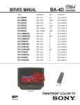
BA-4D CHASSIS
SERVICE MANUAL
MODEL
COMMANDER
DEST
CHASSIS NO.
KV-20M42
KV-20M42
KV-20S42
KV-20S42
KV-20S43
KV-20S43
KV-21MB42C
KV-21MB42M
KV-21MB42P
KV-21ME42
KV-21ME42C
KV-21SB42C
KV-21SB42M
KV-21SE42
KV-21SE42C
KV-21SE82
KV-21SE82C
RM-Y156
US
SCC-S27A-A
RM-Y156
CND
SCC-S28B-A
RM-Y155
US
SCC-S27B-A
RM-Y155
CND
SCC-S28C-A
RM-Y156W
US
SCC-S27C-A
RM-Y156W
CND
SCC-S28D-A
RM-Y156
E
SCC-S25E-A
RM-Y156
MX
SCC-S26A-A
RM-Y156
E
SCC-S25A-A
RM-Y156
E
SCC-S25B-A
RM-Y156
E
SCC-S25F-A
RM-Y155
E
SCC-S25G-A
RM-Y155
MX
SCC-S26B-A
RM-Y155
E
SCC-S25D-A
RM-Y155
E
SCC-S25H-A
RM-Y165
E
SCC-S25J-A
RM-Y165
E
SCC-S25K-A
RM-Y155
KV-21SE82
MICROFILM
TRINITRON® COLOR TV
KV-20M42/20S42/20S43/21MB42C/21MB42M/21MB42P/21ME42/21ME42C/
21SB42C/21SB42M/21SE42/21SE42C/21SE82/21SE82C
SPECIFICATIONS
KV-20M42
KV-21MB42C,
KV-21MB42M,
KV-21MB42P
KV-21ME42,
KV-21ME42C
120V 60Hz
AUTO VOLT
120-220V,
50/60 Hz
2
KV-20S42,
KV-20S43
KV-21SB42C,
KV-21SB42M
KV-21SE42,
KV-21SE42C
KV-21SE82,
KV-21SE82C
AUTO VOLT
120-220V,
50/60 Hz
120V 60 Hz
AUTO VOLT
120-220V,
50/60 Hz
AUTO VOLT
120-220V,
50/60 Hz
AUTO VOLT
120-220V,
50/60 Hz
2
2
2
2
2
2
2
2
2
2
2
2
2
-
-
-
-
-
-
1
3W
3W
3Wx2
3W x 2
3Wx2
4Wx2
5Wx2
In Use (Max)
80W
80W
80W
90W
90W
90W
90W
In Standby
1W
1W
1W
1W
1W
1W
1W
522 x 477 x 479
mm
522 x 477 x 479
mm
522 x 477 x 479
mm
522 x 477 x 479
mm
522 x 477 x 479
mm
522 x 477 x 479
mm
522 x 477 x 479
mm
Power Requirements
Number of inputs/outputs
Video 1)
Audio Input
Audio Out
2)
3)
Speaker Output (W)
Power Consumption (W)
Dimensions (W/H/D)
(mm)
205/8 x 1813/16 x 205/8 x 1813/16 x 205/8 x 1813/16 x 205/ 8 x 1813/16 x 205/ 8 x 1813/16 x 205/ 8 x 1813/16 x 205/ 8 x 1813/16 x
(in)
187/8 in.
187/8 in.
187/8 in.
187/8 in.
187/8 in.
187/8 in.
187/8 in.
(kg)
21.6 kg
21.6 kg
21.6 kg
21.6 kg
21.6 kg
21.6 kg
21.6 kg
(lbs)
48 lbs.
48 lbs.
48 lbs.
48 lbs.
48 lbs.
48 lbs.
48 lbs.
Mass
1) 1
Vp-p 75 ohms unbalanced, sync negative
2 ) 500
Television system
American TV standard/NTSC
3)
mVrms (100% modulation), impedance: 47 kilohms
More than 408 mVrms at the maximum volume setting (variable)
More than 408 mVrms (fix), Impedance: 5 kilohms
Picture tube
Trinitron® Tube
Channel coverage
VHF:2-13/UHF:14-69/CATV:1-125
Visible screen size
20" picture measured diagonally
Actual screen size
21" picture measured diagonally
Antenna
75 ohm external terminal for VHF/UHF
Supplied Accessories
Remote Commander (RM-Y155)
(KV-20S42/21SB42M/42C/21SE42/42C)
Remote Commander (RM-Y156)
(KV-20M42/21MB42C/42M/42P/21ME42/42C)
Remote Commander (RM-Y156W)
(KV-20S43)
Remote Commander (RM-Y165)
(KV-21SE82/82C)
Size AA (R6) batteries (2)
•
•
(
) SRS (SOUND RETRIEVAL SYSTEM)
The ( ) SRS (SOUND RETRIEVAL SYSTEM) is
manufactured by Sony Corporation under license
from SRS Labs, Inc. It is covered by U.S. Patent No.
4,748,669. Other U.S. and foreign patents pending.
Optional Accessories
Dipole antenna
Connecting cables VMC-810S/820S, VMC-720M,
YC-15V/30V, RK74A
U/V mixer EAC-66
•
The word ‘SRS’ and the SRS symbol ( ) are
registered trademarks of SRS Labs, Inc.
Design and specifications are subject to change without notice.
—2—
BBE and BBE symbol are trademarks of BBE
Sound, Inc. and are licensed by BBE Sound, Inc.
under U.S. Patent No. 4,638,258 and 4,482,866.
KV-20M42/20S42/20S43/21MB42C/21MB42M/21MB42P/21ME42/21ME42C/
21SB42C/21SB42M/21SE42/21SE42C/21SE82/21SE82C
TABLE OF CONTENTS
Section
Title
Page
Warnings and Cautions .................................................................................................................................................. 4
Self-Diagnostic Function ................................................................................................................................................. 4
Safety Check Out Instructions ........................................................................................................................................ 7
1.
2.
GENERAL ............................................................................................................................................................ 8
DISASSEMBLY
2-1.
2-2.
2-3.
2-4.
3.
SET-UP ADJUSTMENTS
3-1.
3-2.
3-3.
3-4.
3-5.
3-6.
4.
6-4.
Block Diagram ............................................................................................................................................................... 27
Circuit Board Location .................................................................................................................................................. 30
Printed Wiring Boards and Schematic Diagrams ......................................................................................................... 33
• A Board ..................................................................................................................................................................... 33
• C Board .................................................................................................................................................................... 42
Semiconductors ............................................................................................................................................................ 43
EXPLODED VIEWS
7-1.
7-2.
8.
Setting the Service Adjustment Mode .......................................................................................................................... 19
Memory Write Confirmation Method ............................................................................................................................. 19
Adjust Buttons and Indicators ....................................................................................................................................... 19
A Board Adjustments .................................................................................................................................................... 22
DIAGRAMS
6-1.
6-2.
6-3.
7.
R582 Confirmation Method (HV Hold-Down Confirmation and Readjustments) .................................................... 17
B+ Voltage Confirmation and Adjustment .................................................................................................................... 17
CIRCUIT ADJUSTMENTS
5-1.
5-2.
5-3.
5-4.
6.
Beam Landing ............................................................................................................................................................... 14
Convergence ................................................................................................................................................................. 15
Focus ............................................................................................................................................................................ 16
Screen (G2) ................................................................................................................................................................... 16
Method of Setting the Service Adjustment Mode .............................................................................. ........................... 16
White Balance Adjustments .......................................................................................................................................... 16
SAFETY RELATED ADJUSTMENTS
4-1.
4-2.
5.
Rear Cover Removal .................................................................................................................................................... 12
A Board Removal .......................................................................................................................................................... 12
Service Position ............................................................................................................................................................ 12
Picture Tube Removal .................................................................................................................................................. 13
Chassis (KV-20S43/21SE42/42C/82/82C/ME42/42C) ................................................................................................. 44
Chassis (KV-20M42/S42/21MB42C/42M/42P/SB42C/42M) ........................................................................................ 45
ELECTRICAL PARTS LIST ...........................................................................................................................47
Table of Contents for Parts List ...........................................................................................................................................47
A Board Common Parts Listing............................................................................................................................................48
C Board Parts List................................................................................................................................................................56
A Board Variant Parts Lists...................................................................................................................................................57
Packaging List and Accessories....................................................................................................................................................65
—3—
KV-20M42/20S42/20S43/21MB42C/21MB42M/21MB42P/21ME42/21ME42C/
21SB42C/21SB42M/21SE42/21SE42C/21SE82/21SE82C
WARNINGS AND CAUTIONS
CAUTION
ATTENTION
SHORT CIRCUIT THE ANODE OF THE PICTURE TUBE AND
THE ANODE CAP TO THE METAL CHASSIS, CRT SHIELD, OR
CARBON PAINTED ON THE CRT, AFTER REMOVING THE
ANODE.
APRES AVOIR DECONNECTE LE CAP DE L'ANODE, COURT-CIRCUITER L'ANODE
DU TUBE CATHODIQUE ET CELUI DE L'ANODE DU CAP AU CHASSIS
METALLIQUE DE L'APPAREIL, OU AU COUCHE DE CARBONE PEINTE SUR LE
TUBE CATHODIQUE OU AU BLINDAGE DU TUBE CATHODIQUE.
WARNING!!
ATTENTION!!
AN ISOLATION TRANSFORMER SHOULD BE USED DURING
ANY SERVICE TO AVOID POSSIBLE SHOCK HAZARD,
BECAUSE OF LIVE CHASSIS. THE CHASSIS OF THIS
RECEIVER IS DIRECTLY CONNECTED TO THE AC POWER
LINE.
AFIN D'EVITER TOUT RESQUE D'ELECTROCUTION PROVENANT D'UN CHÁSSIS
SOUS TENSION, UN TRANSFORMATEUR D'ISOLEMENT DOIT ETRE UTILISÉ
LORS DE TOUT DÉPANNAGE. LE CHÁSSIS DE CE RÉCEPTEUR EST
DIRECTEMENT RACCORDÉ À L'ALIMENTATION SECTEUR.
SAFETY-RELATED COMPONENT WARNING!!
ATTENTION AUX COMPOSANTS RELATIFS A LA SECURITE!!
COMPONENTS IDENTIFIED BY SHADING AND MARK
ON
THE SCHEMATIC DIAGRAMS, EXPLODED VIEWS, AND IN THE
PARTS LIST ARE CRITICAL FOR SAFE OPERATION. REPLACE
THESE COMPONENTS WITH SONY PARTS WHOSE PART
NUMBERS APPEAR AS SHOWN IN THIS MANUAL
OR IN SUPPLEMENTS PUBLISHED BY SONY. CIRCUIT
ADJUSTMENTS THAT ARE CRITICAL FOR SAFE OPERATION
ARE IDENTIFIED IN THIS MANUAL. FOLLOW THESE
PROCEDURES WHENEVER CRITICAL COMPONENTS ARE
REPLACED OR IMPROPER OPERATION IS SUSPECTED.
LES COMPOSANTS IDENTIFIES PAR UNE TRAME ET PAR UNE MARQUE
SUR
LES SCHEMAS DE PRINCIPE, LES VUES EXPLOSEES ET LES LISTES DE
PIECES SONT D'UNEIMPORTANCE CRITIQUE POUR LA SECURITE DU
FONCTIONNEMENT. NE LES REMPLACER QUE PAR DES COMPOSANTS SONY
DONT LE NUMERO DE PIECE EST INDIQUE DANS LE PRESENT MANUEL OU
DANS DES SUPPLEMENTS PUBLIES PAR SONY. LES REGLAGES DE
CIRCUIT DONT L'IMPORTANCE EST CRITIQUE POUR LA SECURITE DU
FONCTIONNEMENT SONT IDENTIFIES DANS LE PRESENT MANUEL. SUIVRE CES
PROCEDURES LORS DE CHAQUE REMPLACEMENT DE COMPOSANTS
CRITIQUES, OU LORSQU'UN MAUVAIS FONTIONNEMENT SUSPECTE.
SELF-DIAGNOSTIC FUNCTION
The units in this manual contain a self-diagnostic function. If an error occurs, the STANDBY/TIMER LED will automatically begin to
flash. The number of times the LED flashes translates to a probable source of the problem. A definition of the STANDBY/TIMER LED
flash indicators is listed in the instruction manual for the user’s knowledge and reference. If an error symptom cannot be reproduced, the
Remote Commander can be used to review the failure occurrence data stored in memory to reveal past problems and how often these
problems occur.
Diagnostic Test Indicators
When an error occurs, the STANDBY/TIMER LED will flash a set number of times to indicate the possible cause of the problem. If
there is more than one error, the LED will identify the first of the problem areas.
Results for all of the following diagnostic items are displayed on screen. No error has occurred if the screen displays a “0”.
Diagnostic Item
Description
Power does not turn on
No. of Times
Self-diagnostic Display/
STANDBY/TIMER
Diagnostic Result
LED Flashes
Does not light
Probable Cause
Location
Detected Symptoms
• Power cord is not plugged in.
• Power does not come on.
• Fuse is burned out (F601).
• No power is supplied to the TV.
• H.OUT (Q502) is shorted (A Board)
• Power does not come on.
• IC701 and Q701 (C Board) are shorted.
• Load on power line is shorted.
• +13V is not supplied. (A Board)
• Has entered standby state after horizontal raster.
• IC541 is faulty. (A Board)
• Vertical deflection pulse is stopped.
• AC power supply is faulty.
+B overcurrent (OCP)*
Vertical deflection stopped*
2 times
4 times
2:0 or 2:1
4:0 or 4:1
• Power line is shorted or power supply is stopped.
White balance failure
(not balanced)
5 times
5:0 or 5:1
• Video OUT (Q394 to 392) is faulty. (A Board) • No raster is generated.
• IC301 is faulty. (A Board)
• Screen (G2) is improperly adjusted.**
* If a +B overcurrent is detected, stoppage of the vertical deflection is detected simultaneously.
The symptom that is diagnosed first by the microcontroller is displayed on the screen.
** Refer to Screen (G2) Adjustments in Sections 3 and 4 of this manual.
—4—
• CRT cathode current detection reference
pulse output is small.
KV-20M42/20S42/20S43/21MB42C/21MB42M/21MB42P/21ME42/21ME42C/
21SB42C/21SB42M/21SE42/21SE42C/21SE82/21SE82C
Display of Standby/Timer LED Flash Count
2 times
4 times
5 times
LED ON 0.3 sec.
LED OFF
3 sec.
LED OFF 0.3 sec.
Diagnostic Item
+B overcurrent
Vertical deflection stopped
White balance failure
STANDBY/TIMER LED
Flash Count*
2 times
4 times
5 times
*One flash count is not used for self-diagnostic.
Stopping the Standby/Timer LED Flash
Turn off the power switch on the TV main unit or unplug the power cord from the outlet to stop the STANDBY/TIMER LED from
flashing.
Self-Diagnostic Screen Display
For errors with symptoms such as “power sometimes shuts off” or “screen sometimes goes out” that cannot be confirmed, it is
possible to bring up past occurrences of failure on the screen for confirmation.
To Bring Up Screen Test
In standby mode, press buttons on the Remote Commander sequentially, in rapid succession, as shown below:
Display
Channel 5
Sound volume
Power ON
Note that this differs from entering the service mode (sound volume + ).
Self Diagnostic Screen Display
SELF DIAGNOSTIC
2:
0
3:
N/A
0
4:
0
5:
1
101:
N/A
0
Numeral “0” means that no fault was detected.
Numeral “1” means a fault was detected one time only.
—5—
KV-20M42/20S42/20S43/21MB42C/21MB42M/21MB42P/21ME42/21ME42C/
21SB42C/21SB42M/21SE42/21SE42C/21SE82/21SE82C
Handling of Self-diagnostic Screen Display
Since the diagnostic results displayed on the screen are not automatically cleared, always check the self-diagnostic screen during
repairs. When you have completed the repairs, clear the result display to “0”.
Unless the result display is cleared to “0”, the self-diagnostic function will not be able to detect subsequent faults after completion
of the repairs.
Clearing the Result Display
To clear the result display to “0”, press buttons on the Remote Commander sequentially when the diagnostic screen is displayed,
as shown below:
Channel 8
ENTER
Quitting the Self-Diagnostic Screen
To quit the entire self-diagnostic screen, turn off the power switch on the Remote Commander or the main unit.
Self-diagnostic Circuit
IC301
Y/CHROMA JUNGLE
FROM
CRT
21 IK IN
FROM
IC521
PIN 7
18 HP/PROTECT
IC541
V. OUT
REF
IC001
SYSTEM
IO-BDAT 36
17 I-PROT
3
SDA 35
37 IO-SDAT
IC003
MEMORY
5
B-DAT
O-LED 18
DISPLAY
+B overcurrent (OCP)
Occurs when an overcurrent on the +B (115V) line is detected by pin 18 of IC301. If the voltage
of pin 18 of IC301 is less than 1V when V.SYNC is more than seven verticals in a period, the
unit will automatically turn off.
Vertical deflection stopped
Occurs when an absence of the vertical deflection pulse is detected by pin 17 of IC001. Power
supply will shut down when waveform interval exceeds 2 seconds.
White balance failure
If the RGB levels* do not balance within 2 seconds after the power is turned on, this error will be
detected by IC301. TV will stay on, but there will be no picture.
*(Refers to the RGB levels of the AKB detection Ref pulse that detects 1K.)
—6—
KV-20M42/20S42/20S43/21MB42C/21MB42M/21MB42P/21ME42/21ME42C/
21SB42C/21SB42M/21SE42/21SE42C/21SE82/21SE82C
SAFETY CHECK-OUT
After correcting the original service problem, perform the
following safety checks before releasing the set to the
customer:
1. Check the area of your repair for unsoldered or poorly
soldered connections. Check the entire board surface
for solder splashes and bridges.
2. Check the interboard wiring to ensure that no wires
are “pinched” or touching high-wattage resistors.
3. Check that all control knobs, shields, covers, ground
straps, and mounting hardware have been replaced.
Be absolutely certain that you have replaced all the
insulators.
Leakage Test
The AC leakage from any exposed metal part to earth
ground and from all exposed metal parts to any exposed
metal part having a return to chassis, must not exceed
0.5 mA (500 microampere). Leakage current can be
measured by any one of three methods.
1. A commercial leakage tester, such as the Simpson
229 or RCA WT-540A. Follow the manufacturers'
instructions to use these instructions.
2. A battery-operated AC milliammeter. The Data
Precision 245 digital multimeter is suitable for this job.
4. Look for unauthorized replacement parts, particularly
transistors, that were installed during a previous
repair. Point them out to the customer and
recommend their replacement.
5. Look for parts which, though functioning, show
obvious signs of deterioration. Point them out to the
customer and recommend their replacement.
6. Check the line cords for cracks and abrasion.
Recommend the replacement of any such line cord
to the customer.
3. Measuring the voltage drop across a resistor by
means of a VOM or battery-operated AC voltmeter.
The “limit” indication is 0.75 V, so analog meters must
have an accurate low voltage scale. The Simpson’s
250 and Sanwa SH-63Trd are examples of passive
VOMs that are suitable. Nearly all battery-operated
digital multimeters that have a 2 VAC range are
suitable (see Figure A).
How to Find a Good Earth Ground
7. Check the B+ and HV to see if they are specified
values. Make sure your instruments are accurate;
be suspicious of your HV meter if sets always have
low HV.
8. Check the antenna terminals, metal trim, “metallized”
knobs, screws, and all other exposed metal parts for
AC leakage. Check leakage as described below.
A cold-water pipe is guaranteed earth ground; the coverplate retaining screw on most AC outlet boxes is also at
earth ground. If the retaining screw is to be used as your
earth ground, verify that it is at ground by measuring the
resistance between it and a cold-water pipe with an
ohmmeter. The reading should be zero ohms. If a coldwater pipe is not accessible, connect a 60- to 100-watt
trouble light (not a neon lamp) between the hot side of the
receptacle and the retaining screw. Try both slots, if
necessary, to locate the hot side on the line; the lamp
should light at normal brilliance if the screw is at ground
potential (see Figure B).
To Exposed Metal
Parts on Set
Trouble Light
AC Outlet Box
Ohmmeter
AC
Voltmeter
(0.75 V)
Cold-water Pipe
Earth Ground
Figure A. Using an AC voltmeter to check AC leakage.
Figure B. Checking for earth ground.
—7—
The instructions mentioned here are partial abstracts from the Operating Instruction
Manual. The page numbers shown reflect those of the
Operating Your
Instruction
Connecting
TV Manual.
GENERAL
User Guide
Connecting Additional Equipment
Connecting Your TV
TV and VCR
Read this chapter before setting up your TV for the first time. This section
covers basic connections in addition to any optional equipment you may
be connecting.
Basic Connections
TV with indoor or outdoor antenna, or CATV cable
Depending on the cable available in your home, choose one of the
connections below:
—8—
1
Connect the coaxial cable from your TV antenna or cable TV to the IN
jack on your VCR.
2
Connect a coaxial cable (not supplied) from the OUT jack on your
VCR to the VHF/UHF IN jack on the TV.
✍
To watch video programs from your VCR, tune your TV to channel 3 or 4 (as
set on the rear of your VCR).
(Optional Connection)
3
✍
If you are connecting to an indoor or outdoor antenna, it will be necessary to
adjust the orientation of the antenna for best reception.
3
4
If your VCR is equipped with video inputs, for best picture quality
you should connect A/V connectors to AUDIO/VIDEO OUT on
your VCR to AUDIO/VIDEO IN on your TV. You can use the
button to switch between the TV and VCR inputs.
KV-20M42/20S42/20S43/21MB42C/21MB42M/21MB42P/21ME42/21ME42C/
21SB42C/21SB42M/21SE42/21SE42C/21SE82/21SE82C
SECTION 1
Connecting Your TV
TV and Cable Box
User Guide
TV, VCR, and Cable box
2
Connect the coaxial cable from the wall to the IN jack on your cable
box.
2
Connect a coaxial cable (not supplied) from the OUT jack on your
cable box to the VHF/UHF IN jack on the TV.
✍
✍
To view channels from your cable box, tune your TV to channel 3 or 4 (as set
on the rear panel of your cable box) and use the cable box’s remote control to
change channels.
If you will be controlling all channel selection through your cable box, you
should consider using the CHANNEL FIX feature on page 17.
1
Connect the coaxial cable from the wall to the IN jack on your cable
box.
2
Connect a coaxial cable (not supplied) from the OUT jack on your
cable box to the IN jack on your VCR.
3
Connect a coaxial cable from OUT on your VCR to VHF/UHF IN on
your TV.
✍
If you will be controlling all channel selection through your cable box, you
should consider using the CHANNEL FIX feature on page 17.
(Optional Connection)
4 If your VCR is equipped with video inputs, for best picture quality
you should connect A/V connectors to AUDIO/VIDEO OUT on
your VCR to AUDIO/VIDEO IN on your TV. You can use the
button to switch between the TV and VCR inputs.
5
6
KV-20M42/20S42/20S43/21MB42C/21MB42M/21MB42P/21ME42/21ME42C/
21SB42C/21SB42M/21SE42/21SE42C/21SE82/21SE82C
—9—
1
Connecting a Camcorder
Using A/V cables, connect AUDIO and VIDEO OUT on your camcorder
to AUDIO and VIDEO IN on your TV.
(Front A/V Panel)
Using the Remote Control and Basic Functions
Using the Remote Control and
Basic Functions
This section shows you how to use more advanced buttons on the remote
control and how to use the on-screen menus.
A/V output
Turns the TV off automatically in approximately 30, 60 or 90
minutes. Cancel by pressing until SLEEP OFF appears.
Instantly turns off the sound. Press again or press
sound.
to restore
Cycles through the available video inputs.
Press once to show current time, (if set) and channel number.
Press again to activate CAPTION VISION settings, if available. To
cancel, press again until DISPLAY OFF appears.
— 10 —
✍
Cycles through the Multi-Channel TV Sound (MTS) options:
STEREO, SAP (Second Audio Programming) and MONO,
(KV-20S42, 20S43 only).
For model KV-13M42, this connection can be made to the A/V input located
on the rear of the TV.
-
-
Press for channel selection, the channel will change after 2
seconds.
Press after selecting a channel using the
immediately activate selection.
-
buttons to
Alternates back and forth between the last two channels selected
with the buttons.
Displays the on-screen menu. Press again to exit the menu at any
time.
Activates highlighted selections in the on-screen menu.
Moves the cursor in the on-screen menu.
Press to restore factory settings while in the on-screen menu.
✍
7
Buttons shown are for remote control RM-Y155, your remote control
may not look exactly like the one illustrated.
9
KV-20M42/20S42/20S43/21MB42C/21MB42M/21MB42P/21ME42/21ME42C/
21SB42C/21SB42M/21SE42/21SE42C/21SE82/21SE82C
Connecting Your TV
Other Information
Other Information
Troubleshooting
If you are having a problem with your TV, try the suggestions below. If
the problem persists, contact your nearest Sony dealer.
❏
❏
Poor or no
picture, good
sound
❏
❏
❏
Adjust PICTURE in the VIDEO menu (page 13).
Adjust BRIGHTNESS in the VIDEO menu (page 13).
Check the antenna and/or cable connections (page 3).
Good picture,
no sound
❏
Press
so that MUTING disappears from the
screen (page 9).
Check your AUDIO settings. Your TV may be set to
SAP (page 14).
❏
❏
— 11 —
❏
❏
No color
❏
Adjust COLOR in the VIDEO menu (page 13).
Only snow
appears on the
screen
❏
Check the CABLE setting in the SET UP menu
(page 17).
Check the antenna and/or cable connections (page 3).
Make sure the channel selected is currently
broadcasting.
Dotted lines or
stripes
❏
❏
Adjust the antenna.
Move the TV away from other electronic equipment.
Some electronic equipment can create electrical noise,
which can interfere with TV reception.
Double images
or ghosts
❏
Check your outdoor antenna or call your cable service.
❏
❏
Cannot receive
higher number
channels (UHF)
when using an
antenna
❏
Cable stations
don’t seem to
work
❏
Remote control
does not
operate
❏
❏
Batteries could be weak. Replace them (page 2).
Move the TV 3-4 feet away from fluorescent lights.
The TV needs
to be cleaned
❏
Clean the TV with a soft dry cloth. Never use strong
solvents such as thinner or benzine, which might
damage the finish of the cabinet.
Lost password
for PARENTAL
CONTROL
❏
In the password screen, enter the following master
password: 4357. After using the master password, you
must create a new password, it cannot be used to
unlock currently blocked programs.
❏
❏
Make sure CABLE is set to OFF in the SET UP menu
(page 17).
Use AUTO PROGRAM to add channels that are not
presently in the memory (page 17).
Make sure CABLE is set to ON in the SET UP menu
(page 16).
Use AUTO PROGRAM to add channels that are not
presently in the memory (page 17).
If, after reading these operating instructions, you have additional questions related to the use of your
Sony television, please call our Direct Response Center at 1-800-222-SONY (7669) (U.S. customers
only) or (416) 499-SONY (7669) (Canadian customers only).
25
26
KV-20M42/20S42/20S43/21MB42C/21MB42M/21MB42P/21ME42/21ME42C/
21SB42C/21SB42M/21SE42/21SE42C/21SE82/21SE82C
❏
Make sure the power cord is plugged in.
If a red light is flashing on the front of your TV for
more than a few minutes, call your local service center.
Check the TV/VIDEO settings: when watching TV, set
to TV; when watching video equipment, set to VIDEO
(page 13).
Check your PARENTAL CONTROL settings, (see
pages 22-23).
Make sure the batteries have been inserted correctly
into the remote control.
Try another channel, it could be station trouble.
No picture, no
sound
User Guide
KV-20M42/20S42/20S43/21MB42C/21MB42M/21MB42P/21ME42/21ME42C/
21SB42C/21SB42M/21SE42/21SE42C/21SE82/21SE82C
SECTION 2
DISASSEMBLY
2-1. REAR COVER REMOVAL
Rear Cover
Four Screws
(BVTP 4x16)
2-2. A BOARD REMOVAL
2-3. SERVICE POSITION
C Board
C Board
Claw
A Board
A Board
— 12 —
KV-20M42/20S42/20S43/21MB42C/21MB42M/21MB42P/21ME42/21ME42C/
21SB42C/21SB42M/21SE42/21SE42C/21SE82/21SE82C
2-4. PICTURE TUBE REMOVAL
Two Screws
WARNING:
BEFORE REMOVING
THE ANODE CAP
Two Speaker Boxes (KV-21SE82/82C ONLY)
High voltage remains in the CRT
even after the power is disconnected.
To avoid electric shock, discharge
CRT before attempting to remove the
anode cap. Short between anode and
CRT coated earth ground strap.
A Board
Degaussing Coil
Tension Spring (B)
Tuner
C Board
Deflection Yoke
Two Screws
Four Tapping Screws
Anode Cap
Coated
Earth
Ground
Strap
Picture Tube
Cushion
ANODE CAP REMOVAL
WARNING: High voltage remains in the CRT even after the power is disconnected. To avoid electrical shock, discharge the CRT before
attempting to remove the anode cap. Short between anode and coated earth ground strap of CRT.
NOTE:
After removing the anode, short circuit the anode of the picture tube and the anode cap to either the metal chassis, CRT shield,
or carbon painted on the CRT.
REMOVAL PROCEDURES
c
b
a
Anode Button
1
Turn up one side of the rubber cap in
the direction indicated by arrow a .
2
Use your thumb to pull the rubber
cap firmly in the direction indicated
by arrow b .
HOW TO HANDLE AN ANODE CAP
1
Do not use sharp objects which may cause damage to the
surface of the anode cap.
2
To avoid damaging the anode cap, do not squeeze the rubber
covering too hard. A material fitting called a shatter-hook terminal
is built into the rubber.
3
Do not force turn the foot of the rubber cover. This may cause
the shatter-hook terminal to protrude and damage the rubber.
— 13 —
3
When one side of the rubber cap
separates from the anode button,
the anode cap can be removed by
turning the rubber cap and pulling
it in the direction of arrow c .
KV-20M42/20S42/20S43/21MB42C/21MB42M/21MB42P/21ME42/21ME42C/
21SB42C/21SB42M/21SE42/21SE42C/21SE82/21SE82C
SECTION 3
SET-UP ADJUSTMENTS
The following adjustments should be made when
a complete realignment is required or when a new
picture tube is installed.
Perform the adjustments in order as follows:
1. Beam Landing
2. Convergence
3. Focus
4. Screen (G2)
5. White Balance
These adjustments should be performed with rated
power supply voltage unless otherwise noted.
Set the controls and switch as follows unless
otherwise noted.
Note: Test equipment required:
•
•
•
•
PICTURE control ................. Normal
BRIGHTNESS control ......... Normal
Color bar pattern generator
Degausser
DC power supply
Digital multimeter
5. Move the deflection yoke forward and adjust so that the
entire screen becomes green.
3-1. BEAM LANDING
Before beginning adjustment procedure:
1. Degauss the entire screen.
2. Feed in the white pattern signal.
Adjustment Procedure
1. Input a raster signal with the pattern generator.
2. Loosen the deflection yoke mounting screw and set the
purity control to the center as shown below.
Purity Control
6. Switch over the raster signal to red and blue and confirm
the condition.
7. When the position of the deflection yoke is determined,
tighten it with the deflection yoke mounting screw.
8. If landing at the corner is not right, adjust by using the disk
magnets.
3. Turn the raster signal of the pattern generator to green.
4. Move the deflection yoke backward and adjust the purity
control so that green is in the center and red and blue are
at the sides evenly.
Blue
Purity control
corrects this area
Red
a
b
c
d
Disk magnets
or rotatable disk
magnets correct
these areas (a-d)
Deflection yoke positioning
corrects these areas
Green
a
c
b
d
— 14 —
KV-20M42/20S42/20S43/21MB42C/21MB42M/21MB42P/21ME42/21ME42C/
21SB42C/21SB42M/21SE42/21SE42C/21SE82/21SE82C
3-2. CONVERGENCE
If the blue dot does not converge with the red and green dots,
perform the following:
Before starting convergence adjustments:
1. Move BMC magnet (a) to correct insufficient H. Static
convergence.
1. Perform FOCUS, V.LIN AND V.SIZE adjustments.
2. Set BRIGHTNESS control to minimum.
2. Rotate BMC magnet (b) to correct insufficient V. Static
convergence.
3. Feed in dot pattern.
3. In either case, repeat Beam Landing Adjustment.
Vertical Static Convergence
PURITY
1. Adjust V.STAT magnet to converge red, green and blue
dots in the center of the screen (vertical movement).
Center dot
V. STAT
R
G
R G B
BMC MAGNET
B
V.STAT magnet
BMC magnet
a
2. Tilt the V.STAT magnet and adjust static convergence
to open or close the V.STAT magnet.
b
Dynamic Convergence Adjustment
Before performing this adjustment, perform Horizontal
and Vertical Static Convergence Adjustment.
When the V.STAT magnet is moved in the direction of
arrows
and
, red, green,