1
INSTRUCTION MANUAL
VISUAL PERFORMANCE® SERIES
SST AND SUR SPEAKERS
Introduction
Thank you for purchasing Sonance Visual Per formance
Single-Stereo Technology ® (SST) or surround (SUR) speakers.
When properly installed your new speakers will give you years
of entertainment pleasure.
®
S AFETY W ARNING :
T HESE SPEAKERS HAVE FAST M OUNT ®
SUR Models:
5.1-Channel Home Theater System
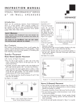
Mount the left and right surround speakers on the ceiling 2 – 6
feet (0.6m – 1.8m) behind the listening position. The speakers
should be 6 – 10 feet (1.8m – 3m) apart. Orient the speakers so
the tweeters face the front and rear walls of the room. Use Figure
2 as a guide.
TABS THAT PREVENT THE
SPEAKER FROM FALLING OUT OF THE MOUNTING HOLE DURING THE
INSTALLATION PROCESS .
T HE
U SE
EDGES OF THE F AST M OUNT TABS ARE
CAUTION WHEN HANDLING THE SPEAKER .
VERY
SHARP.
Box Contents
Item
Visual Performance Speaker
Paintable Grille
Plastic Paint Plug
Mounting Cutout Template
Quantity (SST)
1
1
1
1
Quantity (SUR)
2
2
2
1
Speaker Placement
Because a single SST speaker reproduces both stereo channels
from a single location, it will deliver outstanding performance
from a wide variety of mounting locations where a pair of stereo
speakers would be impractical, including hallways, bathrooms
and closets.
The table below shows how far apart SST speakers can be
spaced in distributed audio applications while still providing
good coverage for standing and seated listeners (see Figure 1 ).
Spacing (Standing)
5’7” (1.7m)
9’7” (3.0m)
13’7” (4.2m)
17.7’ (5.4m)
Spacing (Seated)
9’5” (2.9m)
13’5” (4.1m)
17’5” (5.3m)
21’5” (6.6m)
SPEAKER
SPACING
COVERAGE
AREA
6' – 10'
(1.8m – 3m)
apart
TV
2' – 6'
Left Surround
(0.6m – 1.8m) Speaker
FIGURE 2: SUR SPEAKER PLACEMENT
SST Models
Ceiling Height
9-Foot Ceiling
10-Foot Ceiling
12-Foot Ceiling
14-Foot Ceiling
Right Surround
Speaker
IN A
SUR Models:
7.1-Channel Home Theater System
Mount the left and right surround speakers directly to the sides of
the listening position, 6 – 10 feet (1.8m – 3m) apart. Mount the
surround back speakers 2 – 6 feet (0.6m – 1.8m) behind the
listening position. The surround back speakers should be closer
together than the left and right surround speakers, 3 – 6 feet
(0.9m – 1.8m) apart. Use Figure 3 as a guide.
Right Surround
Speaker
Surround
Back
Speaker
3' – 6'
(0.9m – 1.8m)
apart
2' – 6'
(0.6m – 1.8m)
TV
COVERAGE
AREA
5.1-CHANNEL SYSTEM
Left Surround
Speaker
FIGURE 3: SUR SPEAKER PLACEMENT
IN A
Surround
Back
Speaker
7.1-CHANNEL SYSTEM
FIGURE 1: DISTRIBUTED AUDIO SPEAKER SPACING
1
SONANCE VISUAL PERFORMANCE
Before Installation: Retrofit
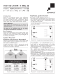
1. Determine the location for the speaker (see
Placement , on page 1).
Speaker
2. Perform an obstruction survey to be certain that there are no
studs, conduit, pipes, heating ducts, pocket doors or air returns
in the wall or ceiling cavity that will interfere with the speaker.
3. M o u n t i n g s p a c e r e q u i r e m e n t s :
• L a r g e r o u n d S S T & S U R : 10 1⁄8 " (257mm) diameter
cut-out; 5 7⁄8 " (149mm) depth within the mounting cavity.
• L a r g e s q u a r e S S T : 10¼" x 10¼" (260mm x 260mm)
cut-out; 5 7⁄8 " (149mm) depth within the mounting cavity.
• M e d i u m r o u n d S S T & S U R : 8¼" (210mm) diameter
cut-out; 4¾" (121mm) depth within the mountinig cavity.
• M e d i u m s q u a r e S S T : 8¼" x 8¼" (210mm x 210mm)
cut-out; 4¾" (121mm) depth within the mounting cavity.
• Medium rectangle SST: 6 15⁄16 " x 10¾" (176mm x 273mm)
cut-out; 3 9⁄16 " (91mm) depth within the mounting cavity.
• M e d i u m T h i n L i n e r o u n d S S T : 8¼" (210mm) diameter
cut-out; 3 1⁄32 " (77mm) depth within the mounting cavity.
• S m a l l r o u n d S S T : 5 7⁄8 " (149mm) diameter cut-out;
3 7/8" (97mm) depth within the mounting cavity.
• S m a l l s q u a r e S S T : 5 5⁄8 " x 5 5⁄8 " (143mm x 143mm)
cut-out; 3 7/8"
" (97mm) depth within the mounting cavity.
4. Position the included cut-out template where the speaker is to
be located and pencil an outline on the wall or ceiling. If you
are unsure about obstructions, drill a small hole in the center
of the outline and insert a coat hanger wire into the hole to
feel-around for possible obstructions.
5. Cut the mounting hole using a keyhole or drywall saw, and
run the speaker wires from the mounting hole to the amplifier
location.
N OTE : C ONSULT
LOCAL BUILDING CODES BEFORE RUNNING
SPEAKER WIRES THROUGH CEILINGS .
Installation
5. Make sure all the RotoLock clamps are in the
full clockwise position
so that they are tucked
within the mounting
hole’s border. Insert the
speaker into the hole in
the wall or ceiling
( Figure 4 ). The RotoLock system can accommodate a maximum
wall or ceiling material
thickness
of
1¼”
(32mm).
®
SST & SUR
Roto-Lock Clamps
(retracted)
The FastMount tabs
will prevent the speaker from falling out of
the mounting hole,
allowing the installer
to let go of the speaker
to pick-up tools or
other items ( Figure 5 ).
FIGURE 4: INSERT SPEAKER INTO
MOUNTING HOLE
FastMount Tabs
NOTE: THE FASTMOUNT
TABS ARE DESIGNED FOR
ONE -TIME
IF
THE
REMOVED
USE
ONLY.
SPEAKER
IS
FROM
THE
HOLE
THE
MOUNTING
FASTMOUNT
DISCONNECT
TABS WILL
AND
FIGURE 5: FASTMOUNT TABS
REMAIN INSIDE THE WALL
OR CEILING.
6. Tighten the four screws on the front of the speaker baffle
( Figure 6 ). The Roto-Lock clamps will automatically rotate into
position and begin clamping the speaker. When you notice resistance on the screws the speaker has been clamped successfully.
Visual Performance SST AND SUR speakers feature exclusive
FastMount tabs and an integral Roto-Lock ® mounting system for
quick mounting directly into existing walls and ceilings.
WARNING: The edges of FastMount tabs are ver y
sharp. Use caution when handling the speaker.
1. Remove the paint plug from the speaker.
2. Run speaker wire from each speaker to the amplifier location.
3. Strip ¼” – ½” (6mm – 12mm) of insulation from each speaker lead. Twist the strands or tin the exposed wire with solder
to ensure that there are no stray strands. (Stray strands that
touch each other can cause a short-circuit that can damage
the amplifier.)
4. The speaker’s connector posts are spring-loaded. Push the top
of each connector post down to open the connector and insert
the exposed wires into the holes in the posts.
• The speaker’s positive post is labeled with a red dot; the negative post is labeled with a black dot. Double-check that you
connected amplifier “+” to speaker “+” and amplifier “–” to
speaker “–”.
2
Roto-Lock
Screws
Roto-Lock
Screws
FIGURE 6: TIGHTENING
THE
ROTO-LOCK SCREWS
SONANCE VISUAL PERFORMANCE ® SST & SUR
N OTE : A DJUSTING
THE TENSION OF THE
R OTO -L OCK
CLAMPS
SO THAT THE SPEAKER FRAME IS FLAT WILL HELP ENSURE THAT THE
GRILLE CONTACTS THE WALL ALL THE WAY AROUND THE SPEAKER
FOR A PROPER FIT.
7. The new micro-trim grille is held in place by several small,
powerful magnets on the speaker frame. Place the grille
against the speaker and the magnets will hold it firmly in
place. When properly installed, the grille trim should make
contact with the wall all the way around the speaker.
Painting The Speakers and Grilles
Please refer to the included Painting Instructions sheet.
Speaker Adjustments
Pivoting Woofer
Some SST and SUR models have a pivoting woofer assembly. This
allows you to direct sound toward or away from the listening
area, depending on how the speakers are being used:
• For SST models, pivoting the woofer towards the listening
position will maximize the speaker’s clarity and definition.
• For SUR models, you can create a more diffuse, spacious
surround effect by aiming the woofers towards a wall or
window, away from the listeners.
N OTE : W HEN P IVOTING
THE
WOOFERS
IN
SUR
MODEL
SPEAKERS , MAKE SURE THAT THE TWEETERS REMAIN ORIENTED
TOWARDS THE FRONT AND REAR WALLS FOR SIDE SURROUND
SPEAKERS , AND TOWARDS THE SIDE WALLS FOR SURROUND BACK
SPEAKERS .
To pivot the woofer,
apply pressure on the
outer edge of the
tweeter support bracket, as shown in Figure
7 . Do not touch or
apply pressure to the
woofer cone.
FIGURE 7:
PIVOTING THE WOOFER
3
LIMITED LIFETIME WARRANTY
Sonance warrants to the first end-user purchaser that this Sonance-brand product (“Product”), when purchased from an
authorized Sonance Dealer/Distributor, will be free from defective workmanship and materials for the life of the Product,
except for the grille, which is warranted for five (5) years. Sonance will at its option and expense either repair the defect
or replace the Product with a new or remanufactured Product or a reasonable equivalent.
EXCLUSIONS
TO THE EXTENT PERMITTED BY LAW, THE WARRANTY SET FORTH ABOVE IS IN LIEU OF, AND EXCLUSIVE OF, ALL OTHER
WARRANTIES, EXPRESS OR IMPLIED, AND IS THE SOLE AND EXCLUSIVE WARRANTY PROVIDED BY SONANCE. ALL OTHER
EXPRESS AND IMPLIED WARRANTIES, INCLUDING THE IMPLIED WARRANTIES OF MERCHANTABILITY, IMPLIED WARRANTY OF
FITNESS FOR USE, AND IMPLIED WARRANTY OF FITNESS FOR A PARTICULAR PURPOSE ARE SPECIFICALLY EXCLUDED.
No one is authorized to make or modify any warranties on behalf of Sonance.
The warranty stated above is the sole and exclusive remedy and Sonance’s performance shall constitute full and final
satisfaction of all obligations, liabilities and claims with respect to the Product. IN ANY EVENT, SONANCE SHALL NOT BE
LIABLE FOR CONSEQUENTIAL, INCIDENTAL, ECONOMIC, PROPERTY, BODILY INJURY, OR PERSONAL INJURY DAMAGES
ARISING FROM THE PRODUCT, ANY BREACH OF THIS WARRANTY OR OTHERWISE.
This warranty statement gives you specific legal rights, and you may have other rights which vary from state to state. Some
states do not allow the exclusion of implied warranties or limitations of remedies, so the above exclusions and limitations
may not apply. If your state does not allow disclaimer of implied warranties, the duration of such implied warranties is
limited to period of Sonance’s express warranty.
Your Product Model and Description: Sonance Visual Performance Series SST and SUR Speakers
Additional Limitations and Exclusions from Warranty Coverage: The warranty described above is non-transferable, applies
only to the initial installation of the Product, does not include installation of any repaired or replaced Product, does not
include damage to allied or associated equipment which may result for any reason from use with this Product, and does not
include labor or parts caused by accident, disaster, negligence, improper installation, misuse (e.g. overdriving the
amplifier or speaker, excessive heat or cold or humidity, outdoor installation), or from service or repair which has not been
authorized by Sonance.
Obtaining Authorized Service: To qualify for the warranty, you must contact your authorized Sonance Dealer/Installer or call
Sonance Customer Service at (800) 582-0772, must obtain a return merchandise number (RMA), and must deliver the
Product to Sonance shipping prepaid during the warranty period, together with the original sales receipt, or invoice or other
satisfactory proof of purchase.
©2009 Sonance. All rights reserved. Sonance, Visual Performance, Single-Stereo Technology, FastMount and Roto-Lock
are registered trademarks of Dana Innovations.
Due to continuous product improvement, all features and specifications are subject to change without notice.
For the latest Sonance product specification information visit our website: www.sonance.com
212 Avenida Fabricante • San Clemente, CA 92672-7531 USA • (800) 582-7777 or (949) 492-7777 • FAX: (949) 361-5151
Technical Support: (800) 582-0772
w w w. s o n a n c e . c o m
33-4942
061009aFinal