1
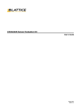
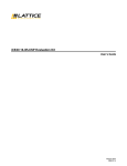
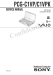
Information in this document is subject to change without notice.
Sony and VAIO are trademarks of Sony. Microsoft, MS-DOS,
Windows, the Windows 95, Windows 98, Windows 2000, Windows
ME and Windows XP logo are trademarks of Microsoft Corporation.
All other trademarks are trademarks or registered trademarks of
their respective owners. Other trademarks and trade names may be
Caution Markings for Lithium/Ion Battery - The following or similar
texts shall be provided on battery pack of equipment or in both the
operating and the service instructions.
CAUTION: Danger of explosion if battery is incorrectly replaced.
Replace only with the same or equivalent type recommended by
the manufacturer. Discard used batteries according to the
manufacturer’s instructions.
used in this document to refer to the entitles claiming the marks and
names or their produces. Sony Corporation disclaims any proprietary
CAUTION: The battery pack used in this device may present a fire
interest in trademarks and trade names other than its own.
or chemical burn hazard if mistreated. Do not disassemble, heat
above 100°C (212°F) or incinerate.
Dispose of used battery promptly.
Keep away from children.
CAUTION: Changing the back up battery.
• Overcharging, short circuiting, reverse charging, multilation
or incineration of the cells must bi avoided to prevent one or
more of the following occurrences; release of toxic materials,
release of hydrogen and/or oxygen gas, rise in surface
temperature.
• If a cell has leaked or vented, it should be replaced
immediately while avoiding to touch it without any protection.
Service and Inspection Precautions
1. Obey precautionary markings and instructions
Labels and stamps on the cabinet, chassis, and components identify areas
requiring special precautions. Be sure to observe these precautions, as
well as all precautions listed in the operating manual and other associated
documents.
2. Use designated parts only
The set’s components possess important safety characteristics, such as
noncombustibility and the ability to tolerate large voltages. Be sure that
replacement parts possess the same safety characteristics as the originals.
Also remember that the 0 mark, which appears in circuit diagrams and
parts lists, denotes components that have particularly important safety
functions; be extra sure to use only the designated components.
After servicing, inspect to make sure that all screws, components, and wiring
have been returned to their original condition. Also check the area around
the repair location to ensure that repair work has caused no damage, and
confirm safety.
5. When replacing chip components...
Never reuse components. Also remember that the negative side of tantalum
capacitors is easily damaged by heat.
6. When handling flexible print boards...
• The temperature of the soldering-iron tip should be about 270˚C.
• Do not apply the tip more than three times to the same pattern.
• Handle patterns with care; never apply force.
3. Always follow the original design when
mounting parts and routing wires
The original layout includes various safety features, such as inclusion of
insulating materials (tubes and tape) and the mounting of parts above the
printer board. In addition, internal wiring has been routed and clamped so
as to keep it away from hot or high-voltage parts. When mounting parts or
routing wires, therefore, be sure to duplicate the original layout.
4. Inspect after completing service
Confidential
PCG-C1MV/C1MVP (AM)
–2–
Caution: Remember that hard disk drives are easily damaged by
vibration. Always handle with care.
TABLE OF CONTENTS
Section
Title
Page
CHAPTER 1. REMOVAL ............................................... 1-1
Please confirm disassembly method by “Repair Manual” which
has been informed you separately.
CHAPTER 2. SELF DIAGNOSTICS .......................... 2-1
Please confirm “Self Diagnostics” method which will be informed
you with distribution of “Self Diagnostics” software.
CHAPTER 3. BLOCK DIAGRAM ............................... 3-1
(to 3-2)
CHAPTER 4. FRAME HARNESS DIAGRAM ........ 4-1
(to 4-2)
CHAPTER 5. EXPLODED VIEWS AND
PARTS LIST
5-1.
5-2.
5-3.
5-4.
•
Main Section .................................................................... 5-1
LCD Section .................................................................... 5-3
Port Assy Section ............................................................. 5-5
Accessories ...................................................................... 5-6
(to 5-6)
Abbreviations
UC : US model / Canadian model
History of the changes is shown as the “Revision
History” at the end of this data.
Confidential
–3–
PCG-C1MV/C1MVP (AM)
CHAPTER 1.
REMOVAL
< ATTENTION >
Please confirm disassembly method by “Repair Manual”
which has been informed you separately.
Confidential
1-1
(END)
PCG-C1MV/C1MVP (AM)
CHAPTER 2.
SELF DIAGNOSTICS
< ATTENTION >
Please confirm “Self Diagnostics” method which will be informed
you with distribution of “Self Diagnostics” software.
Confidential
2-1
(END)
PCG-C1MV/C1MVP (AM)
CHAPTER 3.
BLOCK DIAGRAM
ModeBitRom
microchip
93LC56BT
CPU
Transmeta
Cruesoe(TM)
DDR SDRAM
256Mb × 4
128MB
TM5800
TDM CN 30P
SDRAM
DIMM CN
PCI Debug CN
AD25
1010 000x
(AD11)
PCI Bus (3.3V)
Inverter
CN 6P
IDE(Primary)
50P CN
CN 6P
BT,HDDB,
BATT,PWR
STNDBY LED
CN 20p
LCD
1280 × 600
CN 50P
IFX-166
1-683-136-12
USB3
3
4
USB2
1
USB0
BIOS ROM
2MB
MBM29F016A
AD21
REQ5,GNT5
i.LINK CN
South
Bridge
ALi
M1535+ A1-D
South AD18
IDE AD27
USB1 AD31
USB2 AD26
PMU AD28
AUDIO AD17
MODEM AD19
X-Bus (5V)
RTC
bq3285LD
AD29
REQ2,GNT2
JIG CN 50P
Port80
H8Crisis
SM Bus2
Graphics
ATI Rage
Mobility
M6
AD22
REQ4,GNT4
VGA CN
AD23
REQ3,GNT3
PC Card CN
4
7
Rominfo
AC 97
Yamaha
YMF753
MODEM
Ambit
T60M283.00
7
8
5
8
0100 001x
Clock Gen
IMI
IMIC9716IBTD
RJ11 CN
CAM
Module
SD23
LPC I/F (3.3V)
CN 16p
JOG SW
CN 16p
Sometaro
CXD401
6
HP CN
MS JIG CN
Bus
SW
4MB Flash
USB2
3
0110 000x
Keybaord CN
TP SW
CN 8p
CN 5p
CN 5p
TP
CN 8p
SPKR CN × 2
SWX-84
1-683-135-12
HITACHI
H8S 2149
0101 110x
CAM CN
Bus
SW
1001 100x
USB0
1
SM Bus1
CNX-144
1-683-133-12
SM Bus0
BATT CN
3-1
3-2
(END)
MS CN
USB CN0
IFX-168
1-683-137-12
Battery
0001 011x
MBX-60 1-683-132-12
CN 12P
EC/KBC
Bus
SW
Magic Gate
Sony
CXD3451GA
SUMIRE
TI
F731791C
PBK-TEB
CN 12P
SWX-83 1-683-134-12
I/O Exp
O2micro
OZ998
CNX-147
1-683-138-11
MIC CN
CAM CN
ATF
Analog
Devices
ADM1030
AV IN CN
5
MS,NUM,CAPS,SCRL LED
PWR,CAM,BT SW
USB CN1
L/RIN
COMP IN
VIDEO
Decoder
Philips
SAA7114
6
USB1
AV out CN
PI2C
Selector
MDC CN 30P
L/ROUT
COMP OUT
2
AC LINK
MDC CN 30P
LAN CN
CN 60P
USB1
AD20
REQ0,GNT0
LAN
Realtek
RTL8100BL
CN 60P
2
MPEG2
Real Time
Encoder
KONATSU
CN 40P
BT CN
PC Card
RICOH
R5C475II
(CSP144)
CN 40P
CN 30P
Serial/Parallel
for Debug
24P CN
i.LINK
TI
TSB43AA
22PDT
Confidential
PCG-C1MV/C1MVP (AM)
CHAPTER 4.
FRAME HARNESS DIAGRAM
LCD HOUSING ASSY
MIC
IFX-166 BOARD
FROM board connector (direct connection)
Harness (connector at both end)
Harness (soldered at one end)
LITHIUM ION
BATTERY PACK
INVERTER UNIT
CN2602
LCD
UNIT
Rear
6
CN2102
30
29
2
1
POWER
BUTTON
MODEM
CARD
1
NICKEL HYDROGEN
BATTERY
CN5300
Side L
Side R
1
MODULAR
HARNESS
16
CN1211
1 2
CN2601
26
1
50
HARNESS (MDC TO CNX)
FLEXIBLE FLAT CABLE
CN2600
2 1
DC IN
1
2
CN2100
CN1700
i.LINK
CN1201
1
15
CN1600
2
1
PC
CARD
CONNECTOR
59
60
CN1203
MBX-60 BOARD
SIDE A
1
16
2
40
MBX-60 BOARD
SIDE B
25
49
CN1202
2
1
KEY BOARD
UNIT
1
M
CN1206
5
2
DC FAN
(WITH HEATSINK)
1
FFC (MBX-SWX)
7
CN1204
8
1
CN3220
2
1
HDD
20GB
143
60
J3231
MIC IN
J3230
HEADPHONE OUT
144
CNX-144 BOARD
SIDE A
FLEXIBLE FLAT CABLE
1
EXTENSION
MEMORY MODULE
PCGA-MM128T
(C1MV/C1MVP)
PORT
REPLICATOR
PCGA-PRC1
CN1213
1
59
1
CN3221
2
21
20
50
CN1205
8
CN1210
2
1
CN630
1
2
CN1100
1 2
PRINT PWB SIMPLE
SUBSTANCE
PC
CARD
MODULAR
JACK
HARNESS (DC)
CN1501
1
CAMERA
SHUTTER
SWX-83 BOARD
SIDE A
2 1
LCD HARNESS
JOG
DIAL
CN1212
1
CN2200
1
12
10
12
CN1214
FFC (IFX-CNX)
IFX-168 BOARD
SIDE A
SWX-84 BOARD
SIDE A
Front
MEMORY
STICK
SPEAKER
Rch
SPEAKER
Lch
4-1
Confidential
4-2
(END)
PCG-C1MV/C1MVP (AM)
CHAPTER 5.
EXPLODED VIEWS AND PARTS LIST
Ref.No. Part No.
1
4-655-327-01
2
1-544-951-11
3
4-643-073-11
4
4-641-838-01
5
A-8066-884-A
NOTE:
The components identified by mark 0 or
dotted line with mark 0 are critical for safety.
Replace only with part number specified.
• The mechanical parts with no reference number in the
exploded views are not supplied.
• Items marked “ * ” are not stocked since they are seldom
required for routine service. Some delay should be
anticipated when ordering these items.
• When the same reference numbers are written down in the
list, please use the one listed in the first place as the main
part.
Les composants identifiés par une marque
0 sont critiques pour la sécurité.
Ne les remplacer que par une pièce portant
le numéro spécifié.
5-1. Main Section
Description
RETAINER, SPEAKER
SPEAKER (WITH HARNESS)
SHEET (SPEAKER), ADHESIVE
CUSHION (SP)
MOUNTED PWB SWX-84
Ref.No. Part No.
16
1-823-465-11
17
A-8067-126-A
18
1-823-466-11
* 19
4-656-219-01
21
1-476-912-41
6
7
8
9
10
1-823-467-11
4-655-318-01
X-4623-996-2
X-4623-814-3
4-655-346-01
CABLE, FLEXIBLE FLAT 8P
WINDOW, MS
ESCUTCHEON (MS) SUB ASSY
REST SUB ASSY (B), PALM
BUTTON, POWER
22
23
24
25
26
X-4623-997-1
1-763-741-11
4-654-350-01
A-8067-121-A
4-655-344-02
ESCUTCHEON (L) SUB ASSY
FAN, DC (WITH HEAT SINK)
SHEET (CPU), THERMAL
MBX-60 TM58/733 ASSY (S)
SHEET (PC CARD), INSULATING
11
12
13
14
15
4-655-314-01
1-476-060-71
4-655-460-01
A-8066-887-A
1-793-100-11
LENS (KEYBOARD), LED
ENCODER (ROTARY)
BUTTON, CAPTURE
COMPLETE PWB IFX-168
CONNECTOR, USB
27
28
1-793-637-21
6-701-830-01
29
30
31
4-658-557-01
4-655-345-01
4-655-333-02
CONNECTOR, PC CARD (EJECTOR)
(C1MV/M,C1MVP/M)...
IC M463S1654CT1-L7A
SHEET (FAN), INSULATING
SHEET (BOTTOM), INSULATING
COVER, BATTERY CONNECTOR
32
33
34
35
36
1-761-457-11
4-655-326-01
1-961-397-11
1-468-624-11
1-761-449-11
CARD, MODEM
OFF, STAND
HARNESS (MDC TO CNX)
BATTERY (FOR BACK UP)
PWB, FLEXIBLE PRINT
* 37
38
39
40
41
4-655-311-01
1-761-452-11
A-8025-175-A
1-961-370-11
4-643-040-11
BRACKET, HDD
PWB, FLEXIBLE PRINT (FOR HDD)
ASSY HDD 20GB (I,15) (S)
HARNESS (DC POWER)
COVER (L), MAIN
42
43
44
45
46
4-643-041-11
4-658-021-01
1-961-414-11
A-8066-877-A
1-694-760-21
COVER (R), MAIN
SHEET (MODULAR), INSULATING
HARNESS (MODEM)
COMPLETE PWB CNX-144
JACK, SMALL TYPE (HEAD PHONE)
47
48
49
52
53
1-694-760-31
X-4623-882-2
X-4623-815-2
4-636-934-01
4-635-956-01
JACK, SMALL TYPE (MIC)
ESCUTCHEON (R) SUB ASSY
CABINET SUB ASSY, BOTTOM
SPACER (SPRING)
SPRING (B), COMPRESSION COIL
55
56
58
59
60
4-650-469-01
4-655-339-01
4-659-658-01
4-659-659-01
4-659-656-02
FOOT
LID, MEMORY
CUSHION (HDD)
GASKET (IFX)
SHEET (MBX), INSULATING
61
62
63
64
65
4-659-657-01
4-659-774-01
4-659-683-02
4-645-941-01
4-661-192-02
CUSHION (MDC)
CUSHION (FAN)
SHEET (MS), BLIND
GASKET (RING)
GASKET (SPEAKER)
B1
B2
B3
B4
B5
4-639-112-31
4-657-192-01
4-645-214-01
4-645-214-21
3-930-461-11
SCREW M2X4
SCREW, TAPPING, SPECIAL (2X3)
GRIP, M2 (2X3)
GRIP, M2 (2X5.5)
SCREW (DIA. 1.4X3.5),PRECISION
B6
B7
B8
B9
B10
4-656-239-01
7-628-253-35
4-653-582-11
4-635-301-01
4-659-702-01
M2 SCREW (2X3)
SCREW +PS 2X8
SCREW M2 (NE) (2X5)
SCREW M3X4
SCREW (M2 (EG)), +PS (2X4)
B11
4-644-637-21
GRIP, M2 EG (2X7)
B4
B6
32
25
31
22
34
27
I
9
26
B10
37
33
A
33
8
B9
qd
qd
B
A
1
306
21
qs
H
K
B8
D
B
B10
qa
F
E
B9
0
qg
qh
38
J
23
6
J
35
5
qf
B7
H
2 PCG-C1MV/M,
C1MVP/M
B6
61
24
28
39
B6
36
B6
29
58
60
C
B4
B4
30
64
D
3
8
K
3
9
49
9
19
4
qs
3
1
B4
43
6
52
44
1 6
2
40
41
42
4
B1
Description
FFC 12P
PWB SWX-83 NON-BT ASSY (S)
CABLE, FLEXIBLE FLAT 16P
HEAT SINK
KEYBOARD UNIT (US)
E
62
5
C
5
53
qa
13
7
B5 12
qf
3
B2
11
0
B11
10
59 F
I
qh
B1
7
7
4
65
15
63
B3 16
1
B1
qg
45
B3
B11
8
2
2
G
18
G
17
47
56
55
B1
14
46
48
B3
Confidential
5-1
5-2
PCG-C1MV/C1MVP (AM)
5-2. LCD Section
Ref.No. Part No.
101
X-4623-818-2
102
X-4623-812-2
103
4-646-976-11
104
4-643-078-11
105
A-8067-128-A
128
126
123
125
D
2
122
133
1
119
3
115 (*1)
116
5
C
6
118
114
B15
B13
113 (*2)
112
111
2
136
117
C
B13
B14
124
122
127
135
132
5
120
D
B4
121
4
A
B13
123
B13
129
B6
3
A
1
B
110
B
107
104 B12
Description
COVER SUB ASSY, HINGE
BEZEL SUB ASSY (B), LCD
CUSHION (LATCH)
RUBBER (UNDER), BLIND
LCD 8.9WSXGA ASSY (S)
106
107
108
109
110
1-476-913-11
1-961-294-11
1-961-422-12
4-655-335-01
4-655-343-01
INVERTER UNIT
HARNESS (INVERTER 6P)
HARNESS (LCD)
HINGE (L)
PLATE (CAMERA), ORNAMENTAL
111
112
113
114
115
X-4623-813-1
4-655-341-01
4-655-336-01
4-656-886-01
A-8067-127-A
COVER SUB ASSY, CAMERA
HOLDER, RING
RING, FOCUS
SHEET (CAMERA), PROTECTION
CCD BCX-SD23 ASSY (S)
116
117
118
119
120
4-655-347-01
4-655-334-01
4-655-445-01
4-655-323-01
4-655-330-02
NUT PLATE
HINGE (C)
BEARING (C)
CABINET, CAMERA
DETECTOR
121
122
123
124
125
4-656-052-01
4-655-340-01
4-656-237-01
4-655-316-13
1-542-472-11
PLATE (SMALL), GROUND
LATCH
SPRING, COMPRESSION
LENS (HOUSING), LED
MICROPHONE, ELECTRET CONDENSER
126
127
128
129
132
X-4623-816-2
A-8067-124-A
4-660-539-01
4-661-726-01
4-659-134-01
HOUSING SUB ASSY (B)
IFX-166 NON-BT ASSY (S)
SHEET (CAMERA), ESD
SHEET (KEL), ADHESIVE
CUSHION (HOUSING)
133
135
136
136
136
4-659-655-01
4-659-652-03
4-655-312-21
4-655-312-31
4-655-312-61
SHEET (EMI), HINGE
SHEET (IFX-166), INSULATING
(C1MV)...LABEL (ID)
(C1MVP)...LABEL (ID)
(C1MV/M)...LABEL (ID)
136
B4
B6
B12
B13
4-655-312-71
4-645-214-21
4-656-239-01
4-653-582-21
4-653-582-31
(C1MVP/M)...LABEL (ID)
GRIP, M2 (2X5.5)
M2 SCREW (2X3)
SCREW M2 (NE) (2X6)
SCREW M2 (NE) (2X4)
B14
B15
4-645-497-21
3-318-382-31
SCREW (M2.6),CROSS (HOLE) BIND
SCREW (1.7X3), TAPPING
109
108
6
106
not dismantle the CCD BCX-SD23 assy (Ref. 115).
*1 Do
For example, removing the connector.
mounting the focus ring (Ref. 113), align markings of
*2 When
camera (side of gear) and groove of focus ring.
4
103
105
101
If disintegrated, do not turn focus ring (Ref. 113).
Focus adjustment is off.
102
104
B12
101
Confidential
PCG-C1MV/C1MVP (AM)
5-3
5-4
5-3. Port Assy Section
211
210
213
B18
Ref.No. Part No.
201
4-655-763-01
202
4-655-758-02
* 203
4-655-760-01
204
A-8066-914-A
205
1-794-548-11
Description
FOOT, RUBBER
CABINET (LOWER)
PLATE, CONNECTOR
COMPLETE PWB CNX-147
CONNECTOR, USB (A)
* 206
207
208
209
210
4-656-128-01
1-823-344-11
4-655-761-01
4-656-127-02
X-4624-077-2
BRACKET
CABLE, I/F
HOLDER, CONNECTOR
ESCUTCHEON (CONNECTOR)
CABINET (UPPER) SUB ASSY
211
212
213
B16
B17
4-655-762-01
4-659-565-01
4-659-666-01
7-685-105-14
4-635-966-12
LABEL, CONNECTOR
SHEET (PORT REPLICATOR)
GASKET
TAPPING +P 2X8 NON-SLIT
SCREW (HEX)
B18
4-639-112-01
SCREW M2X4
208
209
B18
206
208
207
205
212
204
203
B17
202
B16
201
201
B16
B16
Confidential
5-5
PCG-C1MV/C1MVP (AM)
5-4. Accessories
Ref.No. Part No.
Description
ACCESSORIES
***********
301
0301
303
306
0307
308
309
303
1-757-562-31
1-757-673-11
4-655-329-01
1-476-942-11
1-756-074-41
CORD, POWER
CORD, CONNECTION
CAP (IN BAG), SENSOR
ADAPTOR, AC
BATTERY PACK, LITHIUM ION
PORT ASSY
4-659-022-01
QUICK START, C1MVP, MV
AV Connecting Cable
The components identified by mark 0 or
dotted line with mark 0 are critical for safety.
Replace only with part number specified.
306
Les composants identifiés par une marque
0 sont critiques pour la sécurité.
Ne les remplacer que par une pièce portant
le numéro spécifié.
Spare Cap
(for Stick)
307
AC Adaptor
308
Battery Pack
309
Port Replicator
*Refer to “5-3. Port Assy Section’’
Confidential
PCG-C1MV/C1MVP (AM)
5-6
(END)
PCG-C1MV/C1MVP (AM)
List of PCG-C1 Series for American Area
(As of January, 2002)
Model
Service Manual
Parts No.
PCG-C1XS
9-872-053-11
PCG-C1VN
9-872-126-11
PCG-C1VP
PCG-C1VPK
9-874-422-11
PCG-C1MV
PCG-C1MV/M
PCG-C1MVP
PCG-C1MVP/M
9-874-449-01
*
*
: Additional Model
American Area : North, Central and South Americas
This manual and the constituent data may not be
replicated, copied nor reprinted in whole or in part
without prior written authorization of Sony Corporation.
Sony Corporation
9-874-449-01
– 24 –
English
2002A0500-1
© 2002 Sony Corporation
Published by Sony EMCS VAIO-GSC [SNT]
Revision History
Suffix
Ver.
Date
-01
Ver. 1
2002.01.23
Contents
QM No.
First Edition
<Remarks>
[Confidential]
PCG-C1MV/C1MVP (AM)