1
INSTRUCTION MANUAL
SONANCE THIN LINE TL622R
6½” IN-CEILING SPEAKER
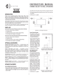
Distributed Audio Placement (Mono Signal)
To reduce noise produced by unsupported drywall, install fiberglass
insulation in the ceiling bays adjacent to the speaker location.
Sonance TL622R in-ceiling speakers have very smooth and
predictable off-axis response, increasing placement options while
providing excellent coverage in distributed audio systems. The chart
below shows how far apart the speakers can be placed while still providing good coverage. The distances are based on ear heights of 62” for
standing listeners and 40” for seated listeners.
Sonafill® Resonance Cancellation System
To dramatically reduce sound transmission to adjacent rooms and
improve speaker performance, Sonance recommends installing the
Sonafill® in-ceiling resonance cancellation system (part# 91928) in each
speaker’s ceiling cavity. Sonafill utilizes acoustic damping tiles and
acoustic absorption pillows to cancel drywall vibration and reduce the
resulting coloration of the speakers’ sound. The Sonafill system can be
easily retrofitted into existing ceilings.
Speaker spacing in feet for a distributed audio system
Standing Listener
Seated Listener
8-foot ceiling
5.7'
9.5'
10-foot ceiling
9.7'
13.5'
12-foot ceiling
13.7'
17.5'
14-foot ceiling
17.7'
21.5'
INSTALLING THE SPEAKERS
New Construction
For installations in new construction, Sonance recommends using
a Symphony FlexBracket (part# 92902) to reserve a location for the
speaker. The FlexBracket is nailed or screwed to the studs and serves as
a guide for the drywaller so that the speaker hole will be in the desired
location once the drywall is installed.
WIRE GAUGE
Extra resistance in the speaker wire can make a speaker sound less
dynamic and reduce definition of the bass frequencies. In extreme cases,
it can even attenuate high frequencies. Also, amplifier power is wasted in
wire with extra resistance, reducing your system’s maximum output level.
Ceiling Joist
To prevent degrading sound quality, the total wire resistance should be
less than 10% of the speaker’s impedance. This means that for an 8-ohm
speaker, the total resistance of the wire should be less than 0.8 ohms.
Refer to the following table when selecting the proper wire gauge for
your system:
FlexBracket Wing
Wire resistance in Ohms vs. length of cable run
Distance in Feet
50' 100' 150' 200' 250' 300'
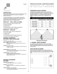
Illustration 4: Symphony FlexBracket Installation
20 gauge
1.04
2.07 3.11
4.14 5.18 6.22
18 gauge
.65
1.30 1.96
2.61 3.26 3.91
Symphony FlexBrackets are compatible with the RotoLock mounting
system (see Retrofit, below).
16 gauge
.41
.82
1.22
1.63 2.04 2.45
Retrofit
14 gauge
.26
.52
.77
1.03 1.29 1.55
12 gauge
.16
.32
.49
.65
.81
.97
TL622R Speakers feature an integral RotoLock® mounting system for
quick mounting directly into existing ceilings and walls. Once the hole is
cut and the cable is run, you can install the speaker in a matter of seconds.
10 gauge
.10
.20
.31
.41
.51
.61
1. Determine the location for the speaker (see Speaker Placement).
2. Perform an obstruction survey to be certain that there are no studs,
conduit, pipes, heating ducts or air returns that will interfere with the
speaker.
3. The cutout for the TL622R speaker is 85/32” (207mm). There also must
be at least 31/16” (77mm) depth within the ceiling cavity for the speaker.
4. Find the cutout template provided in the speaker packaging. Position
the template where the speaker is to be located and pencil an outline
on the ceiling.
• If you are unsure about obstructions, drill a small hole in the center
of the outline and insert a coat hanger wire into the hole to
feel-around for possible obstructions.
5. Cut the hole using a drywall saw, and run the speaker wires.
6. Remove the paint plug from the speaker. Connect the speaker wire to
the terminals on the back of the speaker. Double-check that you connected amplifier + to speaker + and amplifier – to speaker –.
PREPARING THE INSTALLATION LOCATION
All Sonance speakers are designed to be relatively insensitive to
variations in enclosure volume. To achieve the ultimate performance
from your speakers, a section of the ceiling bay can be sectioned-off and
sealed to form a back box. Building such an enclosure will create a
dramatic improvement in bass performance and power handling.
Ideal back box volume requirements:
Thin Line TL622R 1.2 ft3
Insulating the Ceiling Cavity
To reduce sound transmission to adjacent rooms and further improve
speaker performance, insulate the ceiling cavity by inserting a sheet of
unfaced fiberglass insulation behind and around the speaker.
2