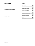
1
Preface
RUGGEDCOM RSG2288
Introduction
1
Installing Device
2
Communication Ports
3
Technical Specifications
4
Dimension Drawings
5
Certification
6
Installation Guide
10/2013
RUGGEDCOM RSG2288
Installation Guide
Copyright © 2013 Siemens AG
All rights reserved. Dissemination or reproduction of this document, or evaluation and communication of its contents, is not authorized
except where expressly permitted. Violations are liable for damages. All rights reserved, particularly for the purposes of patent application or
trademark registration.
This document contains proprietary information, which is protected by copyright. All rights are reserved. No part of this document may be
photocopied, reproduced or translated to another language without the prior written consent of Siemens AG.
Disclaimer Of Liability
Siemens has verified the contents of this manual against the hardware and/or software described. However, deviations between the product
and the documentation may exist.
Siemens shall not be liable for any errors or omissions contained herein or for consequential damages in connection with the furnishing,
performance, or use of this material.
The information given in this document is reviewed regularly and any necessary corrections will be included in subsequent editions. We
appreciate any suggested improvements. We reserve the right to make technical improvements without notice.
Registered Trademarks
ROX™, Rugged Operating System On Linux™, CrossBow™ and eLAN™ are trademarks of Siemens AG. ROS® is a registered trademark of
Siemens AG.
Other designations in this manual might be trademarks whose use by third parties for their own purposes would infringe the rights of the
owner.
Third Party Copyrights
Siemens recognizes the following third party copyrights:
• Copyright © 2004 GoAhead Software, Inc. All Rights Reserved.
Security Information
Siemens provides products and solutions with industrial security functions that support the secure operation of plants, machines, equipment
and/or networks. They are important components in a holistic industrial security concept. With this in mind, Siemens ’ products and solutions
undergo continuous development. Siemens recommends strongly that you regularly check for product updates.
For the secure operation of Siemens products and solutions, it is necessary to take suitable preventive action (e.g. cell protection concept)
and integrate each component into a holistic, state-of-the-art industrial security concept. Third-party products that may be in use should also
be considered. For more information about industrial security, visit http://www.siemens.com/industrialsecurity.
To stay informed about product updates as they occur, sign up for a product-specific newsletter. For more information, visit http://
support.automation.siemens.com.
Warranty
Siemens warrants this product for a period of five (5) years from the date of purchase, conditional upon the return to factory for maintenance
during the warranty term. This product contains no user-serviceable parts. Attempted service by unauthorized personnel shall render all
warranties null and void. The warranties set forth in this article are exclusive and are in lieu of all other warranties, performance guarantees
and conditions whether written or oral, statutory, express or implied (including all warranties and conditions of merchantability and fitness for
a particular purpose, and all warranties and conditions arising from course of dealing or usage or trade). Correction of nonconformities in the
manner and for the period of time provided above shall constitute the Seller’s sole liability and the Customer’s exclusive remedy for defective
or nonconforming goods or services whether claims of the Customer are based in contract (including fundamental breach), in tort (including
negligence and strict liability) or otherwise.
For warranty details, visit www.siemens.com/ruggedcom or contact a Siemens customer service representative.
Contacting Siemens
ii
Address
Telephone
E-mail
Siemens AG
Industry Sector
300 Applewood Crescent
Concord, Ontario
Canada, L4K 5C7
Toll-free: 1 888 264 0006
Tel: +1 905 856 5288
Fax: +1 905 856 1995
[email protected]
Web
www.siemens.com/ruggedcom
RUGGEDCOM RSG2288
Installation Guide
Table of Contents
Table of Contents
Preface ................................................................................................................
v
Alerts .................................................................................................................................................. v
Related Documents ............................................................................................................................. v
Accessing Documentation .................................................................................................................... v
Training .............................................................................................................................................. vi
Customer Support .............................................................................................................................. vi
Chapter 1
Introduction ..........................................................................................................
1
1.1 Feature Highlights ........................................................................................................................ 1
1.2 Ports, Controls and Indicator LEDs ............................................................................................... 2
Chapter 2
Installing Device ..................................................................................................
5
2.1 Mounting the Device .................................................................................................................... 5
2.1.1 Mounting the Device to a Rack .......................................................................................... 6
2.1.2 Mounting the Device on a DIN Rail .................................................................................... 7
2.1.3 Mounting the Device to a Panel ......................................................................................... 7
2.2 Connecting Power ........................................................................................................................ 8
2.2.1 Connecting AC Power ....................................................................................................... 9
2.2.2 Connecting DC Power ..................................................................................................... 10
2.2.3 Wiring Examples ............................................................................................................. 12
2.3 Connecting the Failsafe Alarm Relay ........................................................................................... 14
2.4 Grounding the Device ................................................................................................................. 15
2.5 Connecting to the Device ........................................................................................................... 15
2.6 Cabling Recommendations ......................................................................................................... 16
2.6.1 Protection On Twisted-Pair Data Ports .............................................................................. 16
2.6.2 Gigabit Ethernet 1000Base-TX Cabling Recommendations ................................................. 17
Chapter 3
Communication Ports .........................................................................................
19
3.1 Copper Ethernet Ports ................................................................................................................ 20
3.2 Fiber Optic Ethernet Ports .......................................................................................................... 21
3.3 SFP Optic Ethernet Ports ........................................................................................................... 21
3.3.1 Installing an SFP Optical Port .......................................................................................... 22
iii
Table of Contents
RUGGEDCOM RSG2288
Installation Guide
3.3.2 Removing an SFP Optical Port ......................................................................................... 23
3.4 GBIC Optic Ethernet Ports .......................................................................................................... 23
3.4.1 Installing a GBIC Optical Port ........................................................................................... 24
3.4.2 Removing a GBIC Optical Port ......................................................................................... 25
3.5 Precision Time Protocol (PTP) Card and IEEE1588 v2 ................................................................. 25
3.5.1 PTP Source Card Connectors .......................................................................................... 26
3.5.2 GPS Antenna Installation ................................................................................................. 27
3.5.3 GPS Antenna Specifications ............................................................................................. 27
3.5.4 GPS Antenna Cabling ...................................................................................................... 28
3.5.5 Lightning Considerations .................................................................................................. 29
3.5.6 Line Amplification and Filtering ......................................................................................... 29
3.5.7 IRIG-B Outputs ................................................................................................................ 29
Chapter 4
Technical Specifications .....................................................................................
31
4.1 Power Supply Specifications ....................................................................................................... 31
4.2 Failsafe Relay Specifications ...................................................................................................... 31
4.3 Supported Networking Standards ................................................................................................ 32
4.4 Copper Ethernet Port Specifications ............................................................................................ 32
4.4.1 Copper Gigabit Ethernet (1 Gbps) Port Specifications ........................................................ 33
4.5 Fiber Optic Ethernet Port Specifications ....................................................................................... 33
4.5.1 10FL Ethernet Optical Specifications ................................................................................ 33
4.5.2 Fast Ethernet (10/100 Mbps) Optical Specifications ........................................................... 34
4.5.3 Gigabit Ethernet (1 Gbps) Optical Specifications ................................................................ 34
4.6 PTP Specifications ..................................................................................................................... 35
4.7 Operating Environment ............................................................................................................... 36
4.8 Mechanical Specifications ........................................................................................................... 36
Chapter 5
Dimension Drawings ..........................................................................................
37
Chapter 6
Certification ........................................................................................................
41
6.1 Agency Approvals ...................................................................................................................... 41
6.2 FCC Compliance ........................................................................................................................ 41
6.3 Industry Canada Compliance ...................................................................................................... 41
6.4 EMI and Environmental Type Tests ............................................................................................. 42
iv
RUGGEDCOM RSG2288
Installation Guide
Preface
Preface
This guide describes the RUGGEDCOM RSG2288. It describes the major features of the device, installation,
commissioning and important technical specifications.
It is intended for use by network technical support personnel who are responsible for the installation,
commissioning and maintenance of the device. It is also recommended for use by network and system planners,
system programmers, and line technicians.
Alerts
The following types of alerts are used when necessary to highlight important information.
DANGER!
DANGER alerts describe imminently hazardous situations that, if not avoided, will result in death or
serious injury.
WARNING!
WARNING alerts describe hazardous situations that, if not avoided, may result in serious injury and/or
equipment damage.
CAUTION!
CAUTION alerts describe hazardous situations that, if not avoided, may result in equipment damage.
IMPORTANT!
IMPORTANT alerts provide important information that should be known before performing a procedure
or step, or using a feature.
NOTE
NOTE alerts provide additional information, such as facts, tips and details.
Related Documents
Other documents that may be of interest include:
• ROS User Guide for the RSG2288
Accessing Documentation
The latest Hardware Installation Guides and Software User Guides for most RUGGEDCOM products are
available online at www.siemens.com/ruggedcom.
Alerts
v
Preface
RUGGEDCOM RSG2288
Installation Guide
For any questions about the documentation or for assistance finding a specific document, contact a Siemens
sales representative.
Training
Siemens offers a wide range of educational services ranging from in-house training of standard courses on
networking, Ethernet switches and routers, to on-site customized courses tailored to the customer's needs,
experience and application.
Siemens' Educational Services team thrives on providing our customers with the essential practical skills to make
sure users have the right knowledge and expertise to understand the various technologies associated with critical
communications network infrastructure technologies.
Siemens' unique mix of IT/Telecommunications expertise combined with domain knowledge in the utility,
transportation and industrial markets, allows Siemens to provide training specific to the customer's application.
For more information about training services and course availability, visit www.siemens.com/ruggedcom or
contact a Siemens sales representative.
Customer Support
Customer support is available 24 hours, 7 days a week for all Siemens customers. For technical support or
general information, please contact Customer Support at:
Toll Free (North America): 1 866 922 7975
International: +1 905 856 5288
Website: http://support.automation.siemens.com
vi
Training
RUGGEDCOM RSG2288
Installation Guide
Chapter 1
Introduction
Introduction
The RUGGEDCOM RSG2288 is a rugged, fully managed, modular Ethernet switch specifically designed
to operate reliably in electrically harsh and climatically demanding utility substation, railway and industrial
environments. The RSG2288 includes the IEEE 1588 v2 protocol with hardware time stamping, allowing high
precision time synchronization over the Ethernet network with accuracies of 1 μs or better. The RSG2288’s
superior rugged hardware design coupled with the embedded Rugged Operating System (ROS) provides
improved system reliability and advanced cyber security and networking features, making it ideally suited for
creating Ethernet networks for mission-critical, real-time, control applications.
The RSG2288 ’s modular flexibility offers 100/1000BaseX fiber and 10/100/1000BaseTX copper port
combinations. Support for front or rear mount connectors coupled with support for multiple fiber connector types
(SFP, GBIC, LC, SC) without loss of port density makes the RSG2288 highly versatile and suitable for any
application. The RSG2288 is packaged in a rugged, galvanized steel enclosure with industrial grade DIN, panel,
or 48 cm (19 in) rack-mount mounting options.
The following sections provide more information about the RSG2288:
• Section 1.1, “Feature Highlights”
• Section 1.2, “Ports, Controls and Indicator LEDs”
Section 1.1
Feature Highlights
Ethernet Ports
• Up to 9-Gigabit Ethernet ports supporting copper and fiber media
• Up to 9 100FX Fiber Fast Ethernet ports
• 2 port modules for tremendous flexibility
• Fiber types supported include multimode, singlemode, and bidirectional single strand
• Full compliance with IEEE: 802.3, 802.3u & 802.3z
• Non-blocking, store and forward switching
• Full duplex operation and flow control (IEEE 802.3x)
• Industry standard fiber optic connectors: LC, SC, SFP, GBIC
• Long haul optics allow Gigabit distances up to 70 km
Advanced Time Synchronization
• Support for IEEE 1588 v2, GPS, and IRIG-B time synchronization
• Hardware time stamping on all ports including Gigabit
• Transparent clock operation for high precision on switched networks (1us or better)
• Peer-to-peer path delay measurements
• High precision TCXO (Temperature Compensated Oscillator)
• Supports master, slave and transparent clock modes
Feature Highlights
1
Chapter 1
Introduction
RUGGEDCOM RSG2288
Installation Guide
• Support for IRIG-B input and output
Cyber Security Features
• Multi-level user passwords
• SSH/SSL encryption
• MAC-based port security
• Selective port enable/disable
• Port-based network access control using IEEE 802.1x
• VLAN support (IEEE 802.1Q) to segregate and secure network traffic
• RADIUS centralized access management
• SNMPv3 featuring encrypted authentication and session
Rated for Reliability in Harsh Environments
• Immunity to EMI and heavy electrical transients:
▪ Zero-Packet-Loss™ Technology
▪ Meets IEEE 1613 (electric utility substations)
▪ Exceeds IEC 61850-3 (electric utility substations)
▪ Exceeds IEC 61800-3 (variable speed drive systems)
▪ Exceeds NEMA TS-2 (traffic control equipment)
▪ Exceeds IEC 61000-6-2 (generic industrial environment)
• -40 to 85 °C (-40 to 185 °F) operating temperature (no fans)
• Conformal coated printed circuit boards (optional)
• 18 AWG galvanized steel enclosure
• Hazardous Location Certification: Class 1 Division 2
Universal Power Supply Options
• Fully integrated, dual-redundant (optional) power supplies
• Universal high-voltage range: 88-300 VDC or 85-264 VAC
• Popular low voltage ranges: 24 VDC (10-36 VDC), 48 VDC (36-72 VDC)
• Screw or pluggable terminal blocks for reliable, maintenance-free connections
• CSA/UL 60950-1 safety approved to 85 °C (185 °F)
Section 1.2
Ports, Controls and Indicator LEDs
The RSG2288 features various ports, controls and indicator LEDs on the front panel for configuring and
troubleshooting the device.
2
Ports, Controls and Indicator LEDs
RUGGEDCOM RSG2288
Chapter 1
Installation Guide
Introduction
4
5
1
2
3
6
Figure 1: Front Panel
1. Port Status Indicator LEDs 2. Display Mode Indicator LEDs
LEDs 6. RS232 Serial Console Port (RJ45)
Port Status Indicator LEDs
3. Mode Button
4. Alarm Indicator LED
5. Power Module Indicator
These LEDs indicate the state of each port.
When Status mode is selected, these LEDs indicate when ports are active.
• Green (Solid) = Link detected
• Green (Blinking) = Link activity
• Off = No link detected
When Duplex mode is selected, these LEDs indicate when ports are operating in full or half
duplex mode.
• Green (Solid) = Full duplex mode
• Orange (Solid) = Half duplex mode
• Off = No link detected
When Speed mode is selected, these LEDs indicate the port speed.
•
•
•
•
Green (Solid) = 1000 Mb/s
Green (Blinking) = 100 Mb/s
Orange (Solid) = 10 Mb/s
Off = No link detected
Display Mode Indicator LEDs
These LEDs indicate the current display mode for the port status indicator LEDs (i.e. Status,
Duplex or Speed).
Mode button
The Mode button sets the display mode for the port status indicator LEDs (i.e. Status,
Duplex or Speed). It can also be used to reset the device if held for 5 seconds.
Alarm Indicator LED
The alarm indicator LED illuminates when an alarm condition exists.
Power Module Indicator LEDs
These LEDs indicate the status of the power modules.
• Green = The power supply is supplying power
• Red = Power supply failure
• Off = No power supply is installed
RS232 Serial Console Port
Ports, Controls and Indicator LEDs
This port is for interfacing directly with the device and accessing initial management
functions.
3
RUGGEDCOM RSG2288
Installation Guide
Ports, Controls and Indicator LEDs
Chapter 1
Introduction
4
RUGGEDCOM RSG2288
Installation Guide
Chapter 2
Installing Device
Installing Device
The following sections describe how to install the device, including mounting the device, installing/removing
modules, connecting power, and connecting the device to the network.
DANGER!
Electrocution hazard – risk of serious personal injury and/or damage to equipment. Before performing
any maintenance tasks, make sure all power to the device has been disconnected and wait
approximately two minutes for any remaining energy to dissipate.
WARNING!
Radiation hazard – risk of serious personal injury. This product contains a laser system and is
classified as a CLASS 1 LASER PRODUCT. Use of controls or adjustments or performance of
procedures other than those specified herein may result in hazardous radiation exposure.
IMPORTANT!
This product contains no user-serviceable parts. Attempted service by unauthorized personnel shall
render all warranties null and void.
Changes or modifications not expressly approved by Siemens AG could invalidate specifications, test
results, and agency approvals, and void the user's authority to operate the equipment.
IMPORTANT!
This product should be installed in a restricted access location where access can only be gained by
authorized personnel who have been informed of the restrictions and any precautions that must be
taken. Access must only be possible through the use of a tool, lock and key, or other means of security,
and controlled by the authority responsible for the location.
• Section 2.1, “Mounting the Device”
• Section 2.2, “Connecting Power”
• Section 2.3, “Connecting the Failsafe Alarm Relay”
• Section 2.4, “Grounding the Device”
• Section 2.5, “Connecting to the Device”
• Section 2.6, “Cabling Recommendations”
Section 2.1
Mounting the Device
The RSG2288 is designed for maximum mounting and display flexibility. It can be equipped with connectors that
allow it to be installed in a 48 cm (19 in) rack, 35 mm (1.4 in) DIN rail, or directly on a panel.
NOTE
For detailed dimensions of the device with either rack, DIN rail or panel hardware installed, refer to
Chapter 5, Dimension Drawings.
Mounting the Device
5
Chapter 2
RUGGEDCOM RSG2288
Installing Device
Installation Guide
The following sections describe the various methods of mounting the device:
• Section 2.1.1, “Mounting the Device to a Rack”
• Section 2.1.2, “Mounting the Device on a DIN Rail”
• Section 2.1.3, “Mounting the Device to a Panel”
Section 2.1.1
Mounting the Device to a Rack
For rack mount installations, the RSG2288 can be equipped with rack mount adapters pre-installed at the front or
rear of the chassis. Additional adapters are provided to further secure the device in high-vibration or seismically
active locations.
To secure the device to a standard 48 cm (19 in) rack, do the following:
NOTE
The device can be ordered with the communication ports located at the front or rear of the device.
Placing the ports at the rear allows all data and power cabling to be installed and connected at the rear
of the rack.
1.
Make sure the rack mount adapters are installed on the correct side of the chassis.
NOTE
The chassis features multiple mounting holes, allowing the rack mount adapters to be installed up
to 25 mm (1 in) from the face of the device.
1
2
3
3
Figure 2: Rack Mount Adaptors
1. Rear
2. Front
3. Rack Mount Adaptor
2.
If required, install adapters on the opposite side of the device to protect from vibrations.
3.
Insert the device into the rack.
NOTE
Since heat within the device is channelled to the enclosure, it is recommended that 1 rack-unit
of space, or 44 mm (1.75 in), be kept empty above the device. This allows a small amount of
convectional airflow.
Forced airflow is not required. However, any increase in airflow will result in a reduction of ambient
temperature and improve the long-term reliability of all equipment mounted in the rack space.
4.
6
Secure the adapters to the rack using the supplied hardware.
Mounting the Device to a Rack
RUGGEDCOM RSG2288
Chapter 2
Installation Guide
Installing Device
Section 2.1.2
Mounting the Device on a DIN Rail
For DIN rail installations, the RSG2288 can be equipped with panel/DIN rail adapters pre-installed on each side
of the chassis. The adapters allow the device to be slid onto a standard 35 mm (1.4 in) DIN rail.
To mount the device to a DIN rail, do the following:
1.
Align the adapters with the DIN rails and slide the device into place.
1
3
2
2
3
Figure 3: DIN Rail Mounting
1. Panel/DIN Rail Adaptor
2.
2. DIN Rail
3. Screw
Install one of the supplied screws on either side of the device to secure the adapters to the DIN rails.
Section 2.1.3
Mounting the Device to a Panel
For panel installations, the RSG2288 can be equipped with panel/DIN rail adapters pre-installed on each side of
the chassis. The adapters allow the device to be attached to a panel using screws.
To mount the device to a panel, do the following:
1.
Place the device against the panel and align the adapters with the mounting holes.
Mounting the Device on a DIN Rail
7
Chapter 2
RUGGEDCOM RSG2288
Installing Device
Installation Guide
1
1
2
Figure 4: Panel Mounting
1. Screw
2.
2. Panel/DIN Rail Adaptor
Install the supplied screws to secure the adapters to the panel.
Section 2.2
Connecting Power
The RSG2288 supports single or dual redundant AC and/or DC power supplies. The use of two power modules is
recommended to provide redundancy and load balancing.
The RSG2288 can be equipped with either a screw-type or pluggable terminal block, which provides power
to both power supplies. The screw-type terminal block is installed using Philips screws and compression
plates, allowing either bare wire connections or crimped terminal lugs. Use #6 size ring lugs for secure, reliable
connections under severe shock or vibration.
NOTE
• For maximum redundancy in a dual power supply configuration, use two independent power
sources.
• For 100-240 VAC rated equipment, an appropriately rated AC circuit breaker must be installed.
• For 125/250 VDC rated equipment, an appropriately rated DC circuit breaker must be installed.
• A circuit breaker is not required for 12, 24 or 48 VDC rated power supplies.
• It is recommended to provide a separate circuit breaker for each power supply module.
8
Connecting Power
RUGGEDCOM RSG2288
Installation Guide
Chapter 2
Installing Device
• Equipment must be installed according to applicable local wiring codes and standards.
The following sections describe how to connect power to the device:
• Section 2.2.1, “Connecting AC Power”
• Section 2.2.2, “Connecting DC Power”
• Section 2.2.3, “Wiring Examples”
Section 2.2.1
Connecting AC Power
To connect a high AC power supply to the device, do the following:
CAUTION!
Electrical hazard – risk of damage to equipment. Do not connect AC power cables to terminals for DC
power. Damage to the power supply may occur.
CAUTION!
Electrical hazard – risk of damage to equipment. Before testing the dielectric strength (HIPOT) in the
field, remove the metal jumper. This metal jumper connects transient suppression circuitry to chassis
ground and must be removed in order to avoid damage to transient suppression circuitry during testing.
NOTE
The terminal block is divided into separate terminals for each internal power supply. Make sure to
connect the external power supply to the appropriate terminals.
1.
Remove the terminal block cover.
2.
If a screw-type terminal block is installed, remove the screws from the appropriate terminals. Use these
screws along with #6 ring lugs to secure the wires to the terminal block.
3.
Connect the positive wire from the power source to the positive/live (+/L) terminal on the terminal block. For
more information, refer to Section 2.2.3, “Wiring Examples”.
Connecting AC Power
9
Chapter 2
RUGGEDCOM RSG2288
Installing Device
Installation Guide
6
4
7
5
6
4
5
1
2
3
4
5
6
4
7
5
3
6
Figure 5: Terminal Block Wiring
1. Screw-Type Terminal Block 2. Pluggable Terminal Block 3. Jumper
Terminal (-/N) 6. Surge Ground Terminal 7. Chassis Ground Terminal
4. Positive/Live (+/L) Terminal
5. Negative/Neutral (-/N)
4.
Connect the negative wire from the power source to the negative/neutral (-/N) terminal on the terminal block.
For more information, refer to Section 2.2.3, “Wiring Examples”.
5.
Install the supplied metal jumper between terminals 2, 4 and 6 to connect the surge ground terminals to the
chassis ground terminal. The surge ground terminals are used as the ground conductor for all surge and
transient suppression circuitry internal to the unit.
6.
Connect the ground terminal on the power source to the chassis ground terminal on the device. For more
information, refer to Section 2.4, “Grounding the Device”
DANGER!
Electrocution hazard – risk of death, serious personal injury and/or damage to the device. Make
sure the supplied terminal block cover is always installed before the device is powered.
7.
Install the terminal block cover.
Section 2.2.2
Connecting DC Power
To connect a high or low DC power supply to the device, do the following:
CAUTION!
Electrical hazard – risk of damage to equipment. Before testing the dielectric strength (HIPOT) in the
field, remove the metal jumper. This metal jumper connects transient suppression circuitry to chassis
ground and must be removed in order to avoid damage to transient suppression circuitry during testing.
NOTE
The terminal block is divided into separate terminals for each internal power supply. Make sure to
connect the external power supply to the appropriate terminals.
10
Connecting DC Power
RUGGEDCOM RSG2288
Chapter 2
Installation Guide
Installing Device
NOTE
The screw-type terminal block is installed using Philips screws and compression plates, allowing either
bare wire connections or crimped terminal lugs. Use #6 size ring lugs for secure, reliable screws, which
must be removed to make connections.
1.
Remove the terminal block cover.
2.
If a screw-type terminal block is installed, remove the screws from the appropriate terminals. Use these
screws along with #6 ring lugs to secure the wires to the terminal block.
3.
Connect the positive wire from the power source to the positive/live (+/L) terminal on the terminal block. For
more information, refer to Section 2.2.3, “Wiring Examples”.
6
4
7
5
6
4
5
1
2
3
4
5
6
4
7
5
3
6
Figure 6: Terminal Block Wiring
1. Screw-Type Terminal Block 2. Pluggable Terminal Block 3. Jumper
Terminal (-/N) 6. Surge Ground Terminal 7. Chassis Ground Terminal
4. Positive/Live (+/L) Terminal
5. Negative/Neutral (-/N)
4.
Connect the negative wire from the power source to the negative/neutral (-/N) terminal on the terminal block.
For more information, refer to Section 2.2.3, “Wiring Examples”.
5.
Install the supplied metal jumper between terminals 2, 4 and 6 to connect the surge ground terminals to the
chassis ground terminal. The surge ground terminals are used as the ground conductor for all surge and
transient suppression circuitry internal to the unit.
6.
Connect the ground terminal on the power source to the chassis ground terminal on the device. For more
information, refer to Section 2.4, “Grounding the Device”
DANGER!
Electrocution hazard – risk of death, serious personal injury and/or damage to the device. Make
sure the supplied terminal block cover is always installed before the device is powered.
7.
Install the terminal block cover.
Connecting DC Power
11
Chapter 2
Installing Device
RUGGEDCOM RSG2288
Installation Guide
Section 2.2.3
Wiring Examples
The following illustrate how to connect power to single and dual power supplies.
Figure 7: Single AC Power Supply
Figure 8: Single DC Power Supply
12
Wiring Examples
RUGGEDCOM RSG2288
Installation Guide
Chapter 2
Installing Device
Figure 9: Dual AC Power Supply
Figure 10: Dual DC Power Supply
Wiring Examples
13
Chapter 2
RUGGEDCOM RSG2288
Installing Device
Installation Guide
Figure 11: Dual AC/DC Power Supply
Section 2.3
Connecting the Failsafe Alarm Relay
The failsafe relay can be configured to latch based on alarm conditions. The NO (Normally Open) contact is
closed when the unit is powered and there are no active alarms. If the device is not powered or if an active alarm
is configured, the relay opens the NO contact and closes the NC (Normally Closed) contact.
NOTE
Control of the failsafe relay output is configurable through ROS . One common application for this relay
is to signal an alarm if a power failure occurs. For more information, refer to the ROS User Guide for
the RSG2288.
The following shows the proper relay connections.
14
Connecting the Failsafe Alarm Relay
RUGGEDCOM RSG2288
Chapter 2
Installation Guide
Installing Device
1
3
2
Figure 12: Failsafe Alarm Relay Wiring
1. Normally Open
2. Common
3. Normally Closed
Section 2.4
Grounding the Device
The RSG2288 chassis ground terminal uses a #6-32 screw. It is recommended to terminate the ground
connection with a #6 ring lug and torque it to 1.7 N·m (15 lbf·in).
2
3
1
Figure 13: Chassis Ground Connection
1. Stainless Steel Stud
2. #6-32 Screw
3. #6 Ring Lug
Section 2.5
Connecting to the Device
The following describes the various methods for accessing the ROS console and Web interfaces on the device.
For more detailed instructions, refer to the ROS User Guide for the RSG2288.
Grounding the Device
15
Chapter 2
RUGGEDCOM RSG2288
Installing Device
Installation Guide
Management Port
Connect a PC or terminal directly to the management port to access the boot-time control and ROS interfaces.
The management port provides access to ROS's console and Web interfaces.
IMPORTANT!
The management port is intended to be used only as a temporary connection during initial
configuration or troubleshooting.
The management port is a 10/100/1000Base-T copper Ethernet port with an RJ45 connector. The following is the
pin-out for the management port:
8
1
Figure 14: RJ45 Management Port
Pin
Name
Description
1
TX+
Transmit Data+
2
TX-
Transmit Data-
3
RX+
Receive Data+
4
Reserved (Do Not Connect)
5
Reserved (Do Not Connect)
6
RX-
Receive Data-
7
Reserved (Do Not Connect)
8
Reserved (Do Not Connect)
Communication Ports
Connect any of the available Ethernet ports on the device to a management switch and access the ROS console
and Web interfaces via the device's IP address. For more information about available ports, refer to Chapter 3,
Communication Ports.
Section 2.6
Cabling Recommendations
Before connecting the device, be aware of the recommendations and considerations outlined in the following
sections:
• Section 2.6.1, “Protection On Twisted-Pair Data Ports”
• Section 2.6.2, “Gigabit Ethernet 1000Base-TX Cabling Recommendations”
Section 2.6.1
Protection On Twisted-Pair Data Ports
Siemens does not recommend the use of copper cabling of any length for critical, real-time substation automation
applications. All copper Ethernet ports on RUGGEDCOM products include transient suppression circuitry
to protect against damage from electrical transients and conform with IEC 61850-3 and IEEE 1613 Class 1
standards. This means that during a transient electrical event, communications errors or interruptions may occur,
but recovery is automatic.
16
Cabling Recommendations
RUGGEDCOM RSG2288
Chapter 2
Installation Guide
Installing Device
Siemens also does not recommend using copper Ethernet ports to interface with devices in the field across
distances that could produce high levels of ground potential rise (i.e. greater than 2500 V), during line-to-ground
fault conditions.
Section 2.6.2
Gigabit Ethernet 1000Base-TX Cabling Recommendations
The IEEE 802.3ab Gigabit Ethernet standard defines 1000 Mbit/s Ethernet communications over distances of up
to 100 m (328 ft) using all 4 pairs in category 5 (or higher) balanced, unshielded twisted-pair cabling. For wiring
guidelines, system designers and integrators should refer to the Telecommunications Industry Association (TIA)
TIA/EIA-568-A wiring standard that characterizes minimum cabling performance specifications required for proper
Gigabit Ethernet operation. For reliable, error-free data communication, new and pre-existing communication
paths should be verified for TIA/EIA-568-A compliance.
The following table summarizes the relevant cabling standards:
Cabling Category
1000BaseTX Compliant
<5
No
New wiring infrastructure required.
5
Yes
Verify TIA/EIA-568-A compliance.
5e
Yes
No action required. New installations should be designed with Category 5e or higher.
6
Yes
No action required.
>6
Yes
Connector and wiring standards to be determined.
Required Action
Follow these recommendations for copper data cabling in high electrical noise environments:
• Data cable lengths should be as short as possible, preferably 3 m (10 ft) in length. Copper data cables should
not be used for inter-building communications.
• Power and data cables should not be run in parallel for long distances, and should be installed in separate
conduits. Power and data cables should intersect at 90° angles when necessary to reduce inductive coupling.
• Shielded/screened cabling can be used when required. Care should be taken to avoid the creation of ground
loops with shielded cabling.
Gigabit Ethernet 1000Base-TX Cabling
Recommendations
17
RUGGEDCOM RSG2288
Installation Guide
Gigabit Ethernet 1000Base-TX Cabling
Recommendations
Chapter 2
Installing Device
18
RUGGEDCOM RSG2288
Chapter 3
Installation Guide
Communication Ports
Communication Ports
The RSG2288 can be equipped with various types of communication ports to enhance its abilities and
performance.
1
3
5
2
4
6
Figure 15: Port Assignment
Each type of module has a specific location in the RSG2288 chassis:
• Slots 1 to 4 support any combination of two-port fiber or copper Ethernet modules up to 1 Gbps
• Slot 5 supports a one-port fiber or copper Ethernet module up to 1 Gbps
• Slot 6 houses the PTP Source Card
The exact configuration of the device can be determined by reading the factory data file through the ROS user
interface. For more information about how to read the factory data file, refer to the ROS User Guide for the
RSG2288.
Each communication port is equipped with an LED that indicates the link/activity state of the port.
LED State
Description
Green (Solid)
Link established
Green (Blinking)
Link activity
Off
No link detected
1
Figure 16: Port LEDs
1. Port LED
The following sections describe the available communication ports:
• Section 3.1, “Copper Ethernet Ports”
• Section 3.2, “Fiber Optic Ethernet Ports”
• Section 3.3, “SFP Optic Ethernet Ports”
• Section 3.4, “GBIC Optic Ethernet Ports”
19
Chapter 3
RUGGEDCOM RSG2288
Communication Ports
Installation Guide
• Section 3.5, “Precision Time Protocol (PTP) Card and IEEE1588 v2”
Section 3.1
Copper Ethernet Ports
The RSG2288 supports several 10/100/1000Base-TX Ethernet ports that allow connection to standard Category
5 (CAT-5) unshielded twisted-pair (UTP) cables with either RJ45 male connectors. The RJ45 connectors are
directly connected to the chassis ground on the device and can accept CAT-5 shielded twisted-pair (STP) cables.
WARNING!
Electric shock hazard – risk of serious personal injury and/or equipment interference. If shielded
cables are used, make sure the shielded cables do not form a ground loop via the shield wire and the
RJ45 receptacles at either end. Ground loops can cause excessive noise and interference, but more
importantly, create a potential shock hazard that can result in serious injury.
Figure 17: 1 x 10/100/1000Tx with RJ45 Ports (1CG01)
Figure 18: 2 x 10/100/1000Tx with RJ45 Ports (CG01)
Each port features an LED that indicates the state of the port.
State
Description
Yellow (Solid)
Link established
Yellow (Blinking)
Link activity
Off
No link detected
The following are the pin-out descriptions for the RJ45 connectors:
8
1
Figure 19: RJ45 Ethernet Port Pin Configuration
Pin
Description
10/100Base-TX
1000Base-TX
1
RX+
BI_DB+
Receive Data+
or Bi-Directional
2
RX-
BI_DB-
Receive Dataor Bi-Directional
3
TX+
BI_DA+
Transmit Data+
or Bi-Directional
4
Reserved (Do Not Connect)
5
Reserved (Do Not Connect)
6
20
Name
TX-
BI_DA-
Transmit Dataor Bi-Directional
7
Reserved (Do Not Connect)
8
Reserved (Do Not Connect)
Copper Ethernet Ports
RUGGEDCOM RSG2288
Chapter 3
Installation Guide
Communication Ports
For specifications on the available copper Ethernet ports, refer to Section 4.4, “Copper Ethernet Port
Specifications”.
Section 3.2
Fiber Optic Ethernet Ports
Fiber optic Ethernet ports are available with either MTRJ (Mechanical Transfer Registered Jack), LC (Lucent
Connector), SC (Standard or Subscriber Connector) or ST (Straight Tip) connectors. Make sure the Transmit (Tx)
and Receive (Rx) connections of each port are properly connected and matched to establish a proper link.
1
1
2
Figure 21: LC Port
Figure 20: MTRJ Port
1. Tx Connector
1. Tx Connector
2. Rx Connector
1
2
Figure 22: SC Port
1. Tx Connector
2
2. Rx Connector
1
2
Figure 23: ST Port
2. Rx Connector
1. Tx Connector
2. Rx Connector
For specifications on the available fiber optic Ethernet ports, refer to Section 4.5, “Fiber Optic Ethernet Port
Specifications”.
Section 3.3
SFP Optic Ethernet Ports
SFP (Small Form-Factor Pluggable) optic Ethernet ports are available with LC (Lucent Connector) connectors.
Make sure the Transmit (Tx) and Receive (Rx) connections of each port are properly connected and matched to
establish a proper link.
1
2
Figure 24: LC Port
1. Tx Connector
2. Rx Connector
Fiber Optic Ethernet Ports
21
Chapter 3
RUGGEDCOM RSG2288
Communication Ports
Installation Guide
NOTE
SFP modules, as well as their optical ports, can be safely inserted and removed while the chassis is
powered and operating.
The following sections describe how to install and remove SFP optical ports:
• Section 3.3.1, “Installing an SFP Optical Port”
• Section 3.3.2, “Removing an SFP Optical Port”
Section 3.3.1
Installing an SFP Optical Port
To install an SFP optical port, do the following:
CAUTION!
Electrical hazard – risk of damage to equipment. Use only components certified by Siemens with
RUGGEDCOM products. Damage to the module and device may occur if compatibility and reliability
have not been properly assessed.
CAUTION!
Electrical hazard – risk of damage to equipment. Make sure all electrostatic energy is dissipated
before installing or removing components from the device. An electrostatic discharge (ESD) can cause
serious damage to the component once it is outside the chassis.
1.
Make sure all potential electrostatic build-up has been properly discharged to prevent electrostatic
discharges (ESD). This can be accomplished by wearing an ESD wrist strap or by touching Earth or the
chassis ground.
2.
Remove the dust cover from the port opening in the module.
CAUTION!
Mechanical hazard – risk of component damage. SFP optical ports are designed to insert in only
one orientation. Do not force the port into the module.
3.
Remove the port from its packaging.
4.
Insert the port into the module and swing the bail-latch up to lock it in place.
1
2
Figure 25: Installing an SFP Optical Port (Typical)
1. SFP Optical Port
22
2. Metal Bail-Latch
5.
Remove the dust cover from the port.
6.
Connect a cable to the port and test the connection.
Installing an SFP Optical Port
RUGGEDCOM RSG2288
Chapter 3
Installation Guide
Communication Ports
Section 3.3.2
Removing an SFP Optical Port
To remove an SFP optical port, do the following:
CAUTION!
Electrical hazard – risk of damage to equipment. Make sure all electrostatic energy is dissipated before
performing installing or removing components from the device. An electrostatic discharge (ESD) can
cause serious damage to the component once it is outside the chassis.
1.
Make sure all potential electrostatic build-up has been properly discharged to prevent electrostatic
discharges (ESD). This can be accomplished by wearing an ESD wrist strap or by touching Earth or the
chassis ground.
2.
Disconnect the cable from the port.
3.
Swing the metal bail-latch down and pull the port from the module.
1
2
Figure 26: Removing an SFP Optical Port (Typical)
1. SFP Optical Port
2. Metal Bail-Latch
4.
Store the port in an ESD-safe bag or other suitable ESD-safe environment, free from moisture and stored at
the proper temperature (-40 to 85 °C or -40 to 185 °F).
5.
Insert a plug in the empty port opening to prevent the ingress of dust and dirt.
Section 3.4
GBIC Optic Ethernet Ports
GBIC (Gigabit Interface Converter) optic Ethernet ports are available with SC (Standard or Subscriber Connector)
connectors.
1
2
Figure 27: SC Port
1. Tx Connector
2. Rx Connector
The following sections describe how to install and remove GBIC optical ports:
• Section 3.4.1, “Installing a GBIC Optical Port”
Removing an SFP Optical Port
23
Chapter 3
RUGGEDCOM RSG2288
Communication Ports
Installation Guide
• Section 3.4.2, “Removing a GBIC Optical Port”
Section 3.4.1
Installing a GBIC Optical Port
To install a GBIC optical port, do the following:
CAUTION!
Electrical hazard – risk of damage to equipment. Use only components certified by Siemens with
RUGGEDCOM products. Damage to the module and device may occur if compatibility and reliability
have not been properly assessed.
CAUTION!
Electrical hazard – risk of damage to equipment. Make sure all electrostatic energy is dissipated
before installing or removing components from the device. An electrostatic discharge (ESD) can cause
serious damage to the component once it is outside the chassis.
1.
Make sure all potential electrostatic build-up has been properly discharged to prevent electrostatic
discharges (ESD). This can be accomplished by wearing an ESD wrist strap or by touching Earth or the
chassis ground.
2.
Remove the dust cover from the port opening in the module.
CAUTION!
Mechanical hazard – risk of component damage. GBIC optical ports are designed to insert in only
one orientation. Do not force the port into the module.
3.
Remove the port from its packaging.
4.
Squeeze the latches on either side of the port and insert the port into the module.
1
2
3
Figure 28: Installing a GBIC Optical Port
1. GBIC Optical Port Module
24
2. GBIC Optical Port
3. Locking Latch
5.
Release the latches and make sure the module is locked in place.
6.
Remove the dust cover from the port.
7.
Connect a cable to the port and test the connection.
Installing a GBIC Optical Port
RUGGEDCOM RSG2288
Chapter 3
Installation Guide
Communication Ports
Section 3.4.2
Removing a GBIC Optical Port
To remove an GBIC optical port, do the following:
CAUTION!
Electrical hazard – risk of damage to equipment. Make sure all electrostatic energy is dissipated before
performing installing or removing components from the device. An electrostatic discharge (ESD) can
cause serious damage to the component once it is outside the chassis.
1.
Make sure all potential electrostatic build-up has been properly discharged to prevent electrostatic
discharges (ESD). This can be accomplished by wearing an ESD wrist strap or by touching Earth or the
chassis ground.
2.
Disconnect the cable from the port.
3.
Squeeze the latches on either side of the port and pull it from the module.
1
2
3
Figure 29: Removing a GBIC Optical Port
1. GBIC Optical Port Module
2. GBIC Optical Port
3. Locking Latch
4.
Store the port in an ESD-safe bag or other suitable ESD-safe environment, free from moisture and stored at
the proper temperature (-40 to 85 °C or -40 to 185 °F).
5.
Insert a plug in the empty port opening to prevent the ingress of dust and dirt.
Section 3.5
Precision Time Protocol (PTP) Card and IEEE1588
v2
The Precision Time Protocol (PTP) source card module adds the ability to provide time synchronization via IRIGB (Inter Range Instrumentation Group, modulation type B), and to synchronize to an external IRIG-B source or to
the GPS network.
The following are the time synchronization sources supported by the RSG2288, with and without the PTP card:
Removing a GBIC Optical Port
25
Chapter 3
RUGGEDCOM RSG2288
Communication Ports
Installation Guide
Synchronization Source
Without PTP Card
With PTP Card
NTP
Yes
Yes
IEEE 1588 v2
Yes
Yes
IRIG-B PWM
No
Yes
GPS
No
Yes
The following are the time synchronization services supported by the RSG2288, with and without the PTP card:
Synchronization Service
Without PTP Card
With PTP Card
NTP
Yes
Yes
IEEE 1588 v2
Yes
Yes
IRIG-B AM
No
Yes
IRIG-B PWM
No
Yes
NTP (Network Time Protocol) is the standard for synchronizing the clocks of computer systems throughout the
Internet and is suitable for systems that require accuracies in the order of 1 ms.
IRIG-B time synchronization is an even older, established, inter-device time synchronization mechanism providing
accuracy on the order of 1 ms to 1 µs.
The Global Positioning System (GPS), as a source of accurate time, requires an external GPS antenna input to
provide accurate time signals on the order of 500 ns. The RSG2288 can use the GPS receiver on the PTP card
to provide the time base for the system.
IEEE 1588 is designed to fill a niche not well served by either of the two older, dominant protocols, NTP and
IRIG-B. IEEE 1588 is designed for local systems requiring accuracies on the order of 100 ns. IEEE 1588 is also
designed for applications that cannot bear the cost of a GPS receiver at each node or for which GPS signals are
inaccessible. Every Ethernet port on the RSG2288 supports IEEE1588.
The PTP source card module is an ideal product for use in existing installations already well served by NTP,
IRIG-B or GPS. It also provides a migration path for the use of the new IEEE 1588 v2 standard. As more end
devices enter the market with IEEE 1588 compatibility, this card provides an easy transition to this new time
synchronization standard.
Section 3.5.1
PTP Source Card Connectors
The four BNC connectors on the front panel of the PTP card are defined in the table below:
26
PTP Source Card Connectors
RUGGEDCOM RSG2288
Chapter 3
Installation Guide
Communication Ports
1
2
3
4
Figure 30: PTP Card Panel Description
1. AM OUT Connector 2. TTL OUT Connector
Connector 4. GPS IN Connector
3. TTL IN
Connector
Function
AM OUT
IRIG-B126/B127 AM signal
output, software enabled
TTL OUT
IRIG-B006/B007 PWM
or 1 PPS signal output,
software selectable
TTL IN
TTL-level IRIGB PWM signal input
GPS IN
GPS antenna connector.
SeeSection 3.5.2, “GPS
Antenna Installation”.
Note that only one input is active at a time. The IRIG-B PWM input or the GPS input is selected in software. The
color of the LED on the front panel of the PTP card indicates the status of the incoming timing signal, depending
on the input selected:
Color
GPS Input
IRIG-B PWM Input
Green
Lock
Valid signal
Red
Holdover mode (GPS lock has been
achieved but the receiver no longer sees
the minimum number of required satellites.)
Problems with IRIG-B signal
Off
No signal detected
No signal detected
Section 3.5.2
GPS Antenna Installation
The signals received from the GPS satellite network are at a frequency of 1575.42 MHz with a minimum power
of -162 dBW. The GPS antenna must have a clear view of the sky in order to receive the low power signals and
track the maximum number of satellites. Rooftops or other structures clear of obstructions and with a clear view
of the horizon are ideal.
Elements of a typical GPS antenna system include the following:
• Active GPS Antenna (required)
• Coaxial cable to connect the elements (required)
• Lightning arrestor (optional)
• Line Amplifier or Filter (optional)
To ensure correct GPS signal reception, the overall system of antenna, cabling, lightning arrestor, line amplifier
and filters requires a relative gain which should be greater than 5 dBi but less than 18 dBi (to avoid signal
saturation at the receiver input).
Section 3.5.3
GPS Antenna Specifications
There are two major types of GPS antennas: passive and active. A passive antenna requires no power and is
an option when signal strength is not a concern. An active antenna has a built in Low Noise Amplifier (LNA)
GPS Antenna Installation
27
Chapter 3
RUGGEDCOM RSG2288
Communication Ports
Installation Guide
to increase the strength of the signal, and to compensate for the signal loss in a long cable connection. Active
antennas are used when the antenna input is connected to the receiver through a coaxial cable (usually longer
than 3 m) or any high loss transmission path.
The PTP Card requires an active antenna with the following specifications:
Characteristic
Active Antenna
Polarization
Right-Hand Circular Polarized
Receive Frequency
1.57542 GHz ± 1.023 MHz
Power Supply
5 VDC
DC Current
< 10 mA at 3 VDC
Antenna Gain
Select antenna gain based on system configuration
Total Gain at PTP GPS Input (includes antenna gain, cable
loss, lightning arrestor loss, line amplifier gain and filter loss)
Total Gain≤ 18 dBi
Axial Ratio
< 3 dB
Output VSWR
< 2.5
NOTE
• The PTP card’s GPS input provides 5 VDC at up to 10 mA to power the antenna.
• Best results can be achieved with a total gain of 16 dB (includes antenna gain, cable loss, lightning
arrestor loss, line amplifier gain and filter loss) at the antenna input.
Section 3.5.4
GPS Antenna Cabling
Cable Impedance
Siemens recommends low loss 50Ω coaxial cabling.
Cable Delay
Using any length of coaxial cable will add some time delay to the GPS signal, which degrades the accuracy of
the calculated time and position. The time delay is dependent on the type of dielectric material in the cable and
ranges from 1 to 2 ns/ft. The table below gives some examples of the delay that can be expected based on the
dielectric type.
28
Dielectric Type
Time Delay (ns/ft)
Propagation Velocity (% of c)
Solid Polyethylene (PE)
1.54
65.9
Foam Polyethylene (FE)
1.27
80.0
Foam Polystyrene (FS)
1.12
91.0
Air Space Polyethylene (ASP)
1.15-1.21
84-88
Solid Teflon (ST)
1.46
69.4
Air Space Teflon (AST)
1.13-1.20
85-90
GPS Antenna Cabling
RUGGEDCOM RSG2288
Installation Guide
Chapter 3
Communication Ports
Section 3.5.5
Lightning Considerations
Although it is not possible to protect the antenna from a direct lighting strike, the antenna and connected
components can be protected from secondary effects through installation location and protection devices.
Install the antenna at least 15 meters away from and lower than any structures that attract lightning. GPS
antenna damage is usually not the result of a direct lightning strike, but due to high currents induced by the
effects of a lightning strike on a nearby structure. Siemens also recommends installing lightning arrestors in the
antenna line to protect the receiver and connected devices. If a lightning arrestor is installed, it is important to
ensure that it has a low impedance path to the ground.
Section 3.5.6
Line Amplification and Filtering
Although an active antenna has gain, depending on the length of the coaxial cable used, it may not be enough, in
which case a line amplifier will be required as well.
Most active antennas include filters; however, if there is a high potential for electromagnetic interference, such
as from the near field of a radio transmitter, though the antenna system, additional antenna line filtering may be
necessary.
Section 3.5.7
IRIG-B Outputs
The PTP card provides IRIG-B outputs in both AM (Amplitude Modulated) and PWM (Pulse Width Modulated)
formats. The IRIG-B126/B127 signal format is supported on the AM OUT port, and the IRIG-B006/B007 signal
format is supported on the TTL OUT port. Enabling and disabling the outputs, and selecting between PWM and
PPS on the TTL OUT port, is done through software.
The number of IRIG-B devices that can be connected to the AM or PWM sources is dependent on the cabling
type and length as well as the input impedances of the devices. The following simplified circuit schematic shows
the interface between an IRIG-B source and connected devices.
Lightning Considerations
29
Chapter 3
RUGGEDCOM RSG2288
Communication Ports
Installation Guide
RS
RC
VS
1
RL/N
2
3
Figure 31: IRIG-B Simplified Circuit Schematic
1. Source
2. Cabling
3. Device
The maximum number of devices (N) that can be connected to the source is determined by checking if the source
current (IS) required to drive the connected devices is less than the maximum drive current the source can
provide, and verifying that the load voltage (VL) the connected devices see is greater than the minimum required
voltage. For IRIG-B output port specifications, seeSection 3.5.7, “IRIG-B Outputs”.
30
IRIG-B Outputs
RUGGEDCOM RSG2288
Chapter 4
Installation Guide
Technical Specifications
Technical Specifications
The following sections provide important technical specifications related to the device and available modules:
• Section 4.1, “Power Supply Specifications”
• Section 4.2, “Failsafe Relay Specifications”
• Section 4.3, “Supported Networking Standards”
• Section 4.4, “Copper Ethernet Port Specifications”
• Section 4.5, “Fiber Optic Ethernet Port Specifications”
• Section 4.6, “PTP Specifications”
• Section 4.7, “Operating Environment”
• Section 4.8, “Mechanical Specifications”
Section 4.1
Power Supply Specifications
Power Supply Type
24 VDC
48 VDC
Internal Fuse Rating
Minimum
Maximum
10 VDC
36 VDC
6.3 A(F)
36 VDC
72 VDC
3.15 A(T)
d
88 VDC
300 VDC
2 A(T)
d
85 VAC
264 VAC
2 A(T)
HI (125/250 VDC)
HI (110/230 VAC)
Input Range
a
(F) denotes fast-acting fuse
b
(T) denotes time-delay fuse.
c
Power consumption varies based on configuration. 10/100Base-TX ports consume roughly 1 W less than fiber optic ports.
d
The HI power supply is the same power supply for both AC and DC.
ab
Maximum Power
c
Consumption
28 W
Section 4.2
Failsafe Relay Specifications
Parameter
Value (Resistive Load)
Max Switching Voltage
240 VAC, 125 VDC
Rated Switching Current
2 A @ 240 VAC, 0.15 A @ 125 VDC, 2 A @ 30 VDC
Maximum Switching Capacity
150 W, 500 VA
Power Supply Specifications
31
Chapter 4
RUGGEDCOM RSG2288
Technical Specifications
Installation Guide
Section 4.3
Supported Networking Standards
Standard
10 Mbps Ports
100 Mbps Ports
1000 Mbps
Ports
Notes
IEEE 802.3
10BaseT/10BaseFL
IEEE 802.3u
IEEE 802.3x
100BaseTX/100BaseFX
ü
ü
Flow Control
IEEE 802.3z
ü
1000BaseLX
IEEE 802.3ab
ü
1000BaseTx
IEEE 802.3ad
ü
Link Aggregation
ü
ü
IEEE 802.1D
ü
ü
ü
MAC Bridges
IEEE 802.1D
ü
ü
ü
Spanning Tree Protocol (STP)
IEEE 802.1p
ü
ü
ü
Class of Service (CoS)
IEEE 802.1Q
ü
ü
ü
VLAN (Virtual LAN) Tagging
IEEE 802.1w
ü
ü
ü
Rapid Spanning Tree Protocol (RSTP)
IEEE 802.1x
ü
ü
ü
Port-Based Network Access Control
IEEE
802.1Q-2005
(formerly 802.1s)
ü
ü
ü
Multiple Spanning Tree Protocol (MSTP)
Standard
Description
IEEE 802.3
10BaseT
IEEE 802.3u
100BaseTX/100BaseFX
IEEE 802.3z
1000BaseSX/LX
IEEE 802.3ab
1000BaseTx
IEEE 802.3x
Flow Control
IEEE 802.1D
MAC Bridges
IEEE 802.1Q
VLAN (Virtual LAN) Tagging
IEEE 802.1p
Class of Service
IEEE 1588 v2
Precision Time Protocol
Section 4.4
Copper Ethernet Port Specifications
The following details the specifications for copper Ethernet ports that can be ordered with the RSG2288.
32
Supported Networking Standards
RUGGEDCOM RSG2288
Chapter 4
Installation Guide
Technical Specifications
Section 4.4.1
Copper Gigabit Ethernet (1 Gbps) Port Specifications
NOTE
• Maximum segment length is greatly dependent on factors such as fiber quality, and the number
of patches and splices. Consult a Siemens sales associate when determining maximum segment
distances.
• All optical power numbers are listed as dBm averages.
• F51 transceivers are rated for -40 to 85 °C (-40 to 185 °F).
e
Cable Type
Wiring
g
Standard
Maximum
h
Distance
Isolation
> Category 5
TIA/EIA T568A/B
100 m (328 ft)
1.5 kV
f
Order Code
Connector
Duplex
CG01
RJ45
FDX/HDX
f
Shielded or unshielded.
g
Auto-crossover and auto-polarity.
h
Typical distance. Dependent on the number of connectors and splices.
i
RMS 1 minute.
i
Section 4.5
Fiber Optic Ethernet Port Specifications
The following sections list specifications of the optical transceivers used in the modules available for the
RSG2288:
NOTE
Order codes are contained within each product when assembled and configured at the factory. Refer to
the ROS User Guide for the RSG2288 for information on how to obtain the factory configuration data.
• Section 4.5.1, “10FL Ethernet Optical Specifications”
• Section 4.5.2, “Fast Ethernet (10/100 Mbps) Optical Specifications”
• Section 4.5.3, “Gigabit Ethernet (1 Gbps) Optical Specifications”
Section 4.5.1
10FL Ethernet Optical Specifications
Order
Code
Mode
Connector
Type
FL01
MM
ST
Cable
Type
(µm)
62.5/125
50/125
Copper Gigabit Ethernet (1 Gbps) Port Specifications
Tx λ
(typ.)
(nm)
850
Tx min
(dBm)
Tx max
(dBm)
-16
-9
-19.8
-12.8
Rx
Rx
Sensitivity Saturation
(dBm)
(dBm)
-34
-11.2
Distance
(typ.)
(km)
2
Power
Budget
(dB)
18
14.2
33
Chapter 4
RUGGEDCOM RSG2288
Technical Specifications
Installation Guide
Section 4.5.2
Fast Ethernet (10/100 Mbps) Optical Specifications
j
Cable
Type
(µm)
Tx λ
(typ.)
(nm)
Order
Code
Mode
Connector
Type
FXA01
MM
ST
FXA02
MM
SC
FXA03
MM
MTRJ
FXA04
SM
ST
9/125
1310
FXA05
SM
SC
9/125
FXA06
SM
LC
FXA07
SM
FXA08
62.5/125
Tx max.
(dBm)
-19
Rx
Rx
Maximum
Sensitivity Saturation Distance
j
(dBm)
(dBm)
(km)
Power
Budget
(dB)
12
-14
-31
-14
2
-14
-31
-14
2
-14
-31
-14
2
-15
-8
-32
-3
20
17
1310
-15
-8
-31
-7
20
16
9/125
1310
-15
-8
-34
-7
20
19
SC
9/125
1310
-5
0
-34
-3
50
29
SM
LC
9/125
1310
-5
0
-35
3
50
30
FXA09
SM
SC
9/125
1310
0
5
-37
0
90
37
FXA10
SM
LC
9/125
1310
0
5
-37
0
90
37
FXA11
MM
LC
62.5/125
1300
-19
-14
-32
-14
2
13
50/125
62.5/125
50/125
62.5/125
50/125
1300
Tx min.
(dBm)
1300
1300
-22.5
-19
-22.5
-19
-22.5
8.5
12
8.5
12
8.5
Typical distance. Dependent on the cable type, number of connectors and number of splices.
Section 4.5.3
Gigabit Ethernet (1 Gbps) Optical Specifications
Fixed Gigabit Transceivers
Tx λ
m
(nm)
Tx
Minimum
n
(dBm)
850
-9
-2.5
-20
0
0.5
11
9/125
1310
-10
-3
-20
-3
10
10
LC
9/125
1310
-9.5
-3
-21
-3
10
11.5
SM
SC
9/125
1310
-5
0
-20
-3
25
15
SM
LC
9/125
1310
-7
-3
-24
-3
25
17
Order
k
Code
Mode
Connector
Type
FG01
MM
LC
FG02
SM
SC
FG03
SM
FG04
FG05
Cable
Type
l
(µm)
50/125
62.5/125
Tx
Rx
Rx
Maximum
Maximum Sensitivity Saturation Distance
n
n
n
o
(dBm)
(dBm)
(dBm)
(km)
k
These transceivers utilize a distributed feedback (DFB) type laser and are rated for -20 to 85 °C (-4 to 185 °F) operation only.
l
All cabling is duplex type unless specified otherwise.
Power
Budget
(dB)
m
Typical.
n
34
All optical power numbers are listed as dBm averages.
Fast Ethernet (10/100 Mbps) Optical Specifications
RUGGEDCOM RSG2288
Chapter 4
Installation Guide
o
Technical Specifications
Typical distance. The maximum segment length is greatly dependent on factors such as fiber quality, and the number of patches and splices. Consult a Siemens
sales associates when determining maximum segment distances.
SFP Gigabit Transceivers
Tx λ
q
(nm)
Tx
Minimum
r
(dBm)
850
-9
-2.5
-20
0
9/125
1310
-9.5
-3
-19
-3
10
9.5
LC
9/125
1310
-7
-3
-23
-3
25
16
LC
9/125
1550
0
5
-23
-3
70
23
Order
p
Code
Mode
Connector
Type
FG51
MM
LC
FG52
SM
LC
FG53
SM
t
SM
FG54
Cable
Type
(µm)
50/125
62.5/125
Tx
Rx
Rx
Maximum
Maximum Sensitivity Saturation Distance
r
r
r
s
(dBm)
(dBm)
(dBm)
(km)
0.5
0.3
Power
Budget
(dB)
11
p
Operating temperature range of -40 to 85 °C (-40 to 185 °F), unless specified otherwise.
q
Typical.
r
All optical power numbers are listed as dBm averages.
s
Typical distance. The maximum segment length is greatly dependent on factors such as fiber quality, and the number of patches and splices. Consult a Siemens
sales associates when determining maximum segment distances.
t
Operating temperature range of -20 to 85 °C (-4 to 185 °F).
GBIC Gigabit Transceivers
Order
u
Code
Mode
Connector
Type
Cable
Type
(µm)
Tx λ
v
(nm)
Tx
Minimum
w
(dBm)
FG71
SM
SC
9/125
1310
-9.5
-3
-21
-3
10
11.5
FG72
SM
SC
9/125
1310
-7
-3
-24
-3
25
17
y
SM
SC
9/125
1550
0
5
-23
-3
70
23
FG73
Tx
Rx
Rx
Maximum
Maximum Sensitivity Saturation Distance
w
w
w
x
(dBm)
(dBm)
(dBm)
(km)
Power
Budget
(dB)
u
Operating temperature range of -40 to 85 °C (-40 to 185 °F), unless specified otherwise.
v
Typical.
w
All optical power numbers are listed as dBm averages.
x
Typical distance. The maximum segment length is greatly dependent on factors such as fiber quality, and the number of patches and splices. Consult a Siemens
sales associates when determining maximum segment distances.
y
Operating temperature range of -20 to 85 °C (-4 to 185 °F).
Section 4.6
PTP Specifications
IRIG-B PWM Input Specifications
PTP Specifications
Parameter
Typical Value
Input Voltage
TTL-Compatible
Input Impedance
>200 kΩ
35
Chapter 4
RUGGEDCOM RSG2288
Technical Specifications
Installation Guide
IRIG-B003 PWM Output Specifications
Parameter
Typical Value
Output Current (Is)
100 mA
Output Voltage (Vs)
5 Vp-p
Output Impedance (Rs)
50 Ω
IRIG-B123 AM Output Specifications
Parameter
Typical Value
Carrier Frequency
1 kHz
Modulation Depth
3:1±10%
Output Current (Is)
24 mA
Output Impedance (Rs)
10 Ω
Output Voltage (Vs)
6 Vp-p
Section 4.7
Operating Environment
Parameter
Range
Comments
Ambient Operating Temperature
-40 to 85 °C (-40 to 185 °F)
Ambient Temperature as measured from a 30 cm
radius surrounding the center of the enclosure.
Ambient Relative Humidity
5% to 95%
Non-condensing
Ambient Storage Temperature
-40 to 85 °C (-40 to 185 °F)
Section 4.8
Mechanical Specifications
36
Parameter
Value
Dimensions
Refer to Chapter 5, Dimension Drawings
Weight
4.8 kg (10.6 lbs)
Ingress Protection
IP40 (1 mm or 0.04 in objects)
Enclosure
18 AWG Galvanized Steel
Operating Environment
RUGGEDCOM RSG2288
Chapter 5
Installation Guide
Dimension Drawings
Dimension Drawings
NOTE
All dimensions are in millimeters, unless otherwise stated.
303.28
44.45
285.24
438.15
Figure 32: Overall Dimensions
37
Chapter 5
RUGGEDCOM RSG2288
Dimension Drawings
Installation Guide
479.29
4.57
Figure 33: Rack Mount Dimensions
38
31.75
6.35
461.01
6.35
308.10
314.71
28.96
51.05
12.70
25.40
32.77
21.08
11.68
39
Figure 34: Panel and DIN Rail Mount Dimensions
11.4
158.0
80.0
84.1
125.5
159.8
134.4
P1
P2
P3
P4
P5
P6
P7
P8
P9
P10
P11 P12
TX
RX
TX
RX
TX
RX
TX
RX
AM OUT
TTLOUT
TTLIN
GPSIN
7
11
15
19
23
27
31
13 14
17 18
21 22
25 26
29 30
6
10
5
9
3
2
1
4
8
12
16
20
24
28
32
STATUS
DUPLEX
SPEED
127.5
TX
RX
TX
RX
TX
RX
TX
RX
10.4
7.4
ALARM
POWER1
POWER2
CONSOLE
57600-N-8-1
MODE
38.9
51.6
486.4
476.3
Installation Guide
Dimension Drawings
RUGGEDCOM RSG2288
Chapter 5
RUGGEDCOM RSG2288
Installation Guide
Chapter 5
Dimension Drawings
40
RUGGEDCOM RSG2288
Chapter 6
Installation Guide
Certification
Certification
The RSG2288 device has been thoroughly tested to guarantee its conformance with recognized standards and
has received approval from recognized regulatory agencies.
• Section 6.1, “Agency Approvals”
• Section 6.2, “FCC Compliance”
• Section 6.3, “Industry Canada Compliance”
• Section 6.4, “EMI and Environmental Type Tests”
Section 6.1
Agency Approvals
Agency
Standards
Comments
CSA
CSA C22.2 No. 60950-1, UL 60950-1
Approved
CE
EN 60950-1, EN 61000-6-2, EN60825-1,
EN55022 Class A, EN 50581
CE Compliance is claimed via
Declaration of Self Conformity Route
FCC
FCC Part 15, Class A
Approved
FDA/CDRH
21 CFR Chapter I, Sub-chapter J
Approved
ISO
ISO9001:2008
Designed and manufactured using an
ISO9001:2008 certified quality program
Section 6.2
FCC Compliance
This equipment has been tested and found to comply with the limits for a Class A digital device pursuant to Part
15 of the FCC Rules. These limits are designed to provide reasonable protection against harmful interference
when the equipment is operated in a commercial environment.
This equipment generates, uses and can radiate radio frequency energy and, if not installed and used in
accordance with the instruction manual, may cause harmful interference to radio communications. Operation of
this equipment in a residential area is likely to cause harmful interference in which case the user will be required
to correct the interference on his own expense.
Section 6.3
Industry Canada Compliance
CAN ICES-3 (A) / NMB-3 (A)
Agency Approvals
41
Chapter 6
RUGGEDCOM RSG2288
Certification
Installation Guide
Section 6.4
EMI and Environmental Type Tests
The RSG2288 has passed the following EMI and environmental tests.
IEC 61850-3 EMI Type Tests
NOTE
• If the unit contains copper ports, the IEC 1613 conformance is Class 1, during which disturbance
errors may occur but recovery is automatic.
• If the unit contains all fiber ports, the IEC 1613 conformance is Class 2, during which no disturbance
errors will occur.
Test
IEC 61000-4-2
Description
ESD
Test Levels
Severity Levels
Enclosure Contact
+/- 8 kV
4
Enclosure Air
+/- 15 kV
IEC 61000-4-3
Radiated RFI
Enclosure Ports
20 V/m
IEC 61000-4-4
Burst (Fast Transient)
Signal Ports
+/- 4 kV @ 2.5 kHz
D.C. Power Ports
+/- 4 kV
4
Signal Ports
+/- 4kV Line-to-Earth,
+/- 2kV Line-to-Line
4
D.C. Power Ports
+/- 2kV Line-to-Earth,
+/- 1kV Line-to-Line
3
A.C. Power Ports
+/- 4kV Line-to-Earth,
+/- 2kV Line-to-Line
4
Signal Ports
10 V
3
A.C. Power Ports
Earth Ground Ports
IEC 61000-4-5
IEC 61000-4-6
Surge
Induced (Conducted) RFI
D.C. Power Ports
A.C. Power Ports
Earth Ground Ports
IEC 61000-4-8
Magnetic Field
Enclosure Ports
40 A/m, Continuous,
1000 A/m for 1 s
IEC 61000-4-29
Voltage Dips and
Interrupts (D C.
Power Ports)
D.C. Power Ports
30% for 0.1 s
60% for 0.1 s
100% for 0.05 s
A.C. Power Ports
30% for 1 period
60% for 50 periods
IEC 61000-4-11
42
Voltage Dips and
Interrupts (A. C.
Power Ports)
A.C. Power Ports
100% for 5 periods
100% for 50 periods
EMI and Environmental Type Tests
RUGGEDCOM RSG2288
Chapter 6
Installation Guide
Certification
Test
IEC 61000-4-12
Description
Damped Oscillatory
Signal Ports
D.C. Power Ports
Test Levels
Severity Levels
2.5 kV Common,
1 kV Differential
Mode @1 MHz
3
30 V Continuous,
300 V for 1s
4
3
A.C. Power Ports
IEC 61000-4-16
Mains Frequency Voltage
Signal Ports
D.C. Power Ports
IEC 61000-4-17
Ripple on D.C.
Power Supply
D.C. Power Ports
10%
IEC 60255-5
Dialiectric Strength
Signal Ports
2 kVAC (FailSafe Relay Output)
D.C. Power Ports
1.5 kVDC
A.C. Power Ports
2 kVAC
Signal Ports
5 kV (Fail-Safe
Relay Output)
D.C. Power Ports
5 kV
H.V. Impulse
A.C. Power Ports
IEC 1613/C37.90
Dialiectric Strength
H.V. Impulse
IEC 1613/C37.90.1
Oscillatory
Fast Transient
Signal Ports
5 kV (Fail-Safe
Relay Output)
D.C. Power Ports
5 kV
A.C. Power Ports
5 kV
Signal Ports
2 kVAC
D.C. Power Ports
1.5 kVDC
A.C. Power Ports
2 kVAC
Signal Ports
2.5 kV Common
Mode @1 MHz
D.C. Power Ports
A.C. Power Ports
2.5 kV Common,
1 kV Differential
Mode @1 MHz
Signal Ports
+/- 4 kV @ 2.5 kHz
D.C. Power Ports
+/- 4 kV
A.C. Power Ports
Earth Ground Ports
IEEE C37.90.2
Radiated RFI
Enclosure Ports
35 V/m
IEC 1613/C37.90.3
ESD
Enclosure Contact
+/- 8kV
Enclosure Air
+/- 15kV
EMI and Environmental Type Tests
43
Chapter 6
RUGGEDCOM RSG2288
Certification
Installation Guide
IEEE 1613 (C37.90.x) EMI Immunity Type Tests
NOTE
The RSG2288 meets Class 2 requirements for an all-fiber configuration and Class 1 requirements for
copper ports.
Test
IEEE C37.90.3
Description
ESD
Test Levels
Enclosure Contact
+/-8 kV
Enclosure Air
+/-15 kV
IEEE C37.90.2
Radiated RFI
Enclosure Ports
35 V/m
IEEE C37.90.1
Fast Transient
Signal Ports
+/- 4 kV @ 2.5 kHz
D.C. Power Ports
+/- 4 kV
A.C. Power Ports
+/- 4 kV
Earth Ground Ports
+/- 4 kV
Signal Ports
2.5 kV Common Mode @1MHz
D.C. Power Ports
2.5 kV common, 1 kV
differential mode @ 1 MHz
A.C. Power Ports
2.5 kV common, 1 kV
differential mode @ 1 MHz
Signal Ports
5 kV (Fail-Safe Relay Output)
D.C. Power Ports
5 kV
A.C. Power Ports
5 kV
Signal Ports
2 kVAC
D.C. Power Ports
1.5kVDC
A.C. Power Ports
2 kVAC
Oscillatory
IEEE C37.90
IEEE C37.90
H.V. Impulse
Dielectric Strength
Environmental Type Tests
Test
44
Description
Test Levels
IEC 60068-2-1
Cold Temperature
Test Ad
-40 °C (-40 °F), 16 Hours
IEC 60068-2-2
Dry Heat
Test Bd
85 °C (185 °F), 16 Hours
IEC 60068-2-30
Humidity (Damp Heat, Cyclic)
Test Db
95% (non-condensing),
55 °C (131 °F), 6 cycles
IEC 60068-21-1
Vibration
2g @ 10-50 Hz
IEC 60068-21-2
Shock
30 g @ 11 ms
EMI and Environmental Type Tests