1
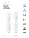
Micro Dimmer
Owner’s Manual
2442-222 (US)
2442-422 (EU)
2442-522 (AUS/NZ)
North America
EU/AUS/NZ
Page 1 of 24
2442-222/2442-422/2442-522 - Rev: 9/24/2014 12:45 PM
About Micro Dimmer ................................................................................................................................. 4
Features and Benefits ............................................................................................................................. 4
Before Installation..................................................................................................................................... 4
Identifying the Electrical Wires in Your Home (North America only) ........................................................ 5
Identifying the Electrical Wires in Your Home (Europe/Australia/New Zealand) ...................................... 5
Identify Switch Type ................................................................................................................................ 5
Installation ................................................................................................................................................. 6
Switch Operation Mode ............................................................................................................................ 7
Change to Single Momentary Mode ........................................................................................................ 7
Change to Dual Momentary Mode........................................................................................................... 7
Change to Latching Mode (default) ......................................................................................................... 8
3-Way Toggle Mode (Latching Switches Only, Default)......................................................................... 8
Local Control Operation ........................................................................................................................... 9
Latching Switch (Default)......................................................................................................................... 9
Single Momentary Switch ........................................................................................................................ 9
Dual Momentary Switch........................................................................................................................... 9
Adjust Local Settings ............................................................................................................................. 10
Local On-Level ...................................................................................................................................... 10
Local Ramp Rate................................................................................................................................... 10
Resume Dim.......................................................................................................................................... 11
Change LED Brightness (or turn it off)................................................................................................... 11
Error Blink.............................................................................................................................................. 12
Blink on Traffic....................................................................................................................................... 12
Beep on Button Press............................................................................................................................ 12
Programming Lock ................................................................................................................................ 12
INSTEON Setup ....................................................................................................................................... 12
INSTEON Controllers, Responders and Links....................................................................................... 12
Configure INSTEON Settings ................................................................................................................ 13
Make Micro Module a Responder (Set button) ...................................................................................... 13
Make Micro Module a Responder (Switch) ............................................................................................ 13
Make Micro Module a Controller (Set button) ........................................................................................ 13
Make Micro Module a Controller (Switch) .............................................................................................. 14
Groups................................................................................................................................................... 14
Scenes .................................................................................................................................................. 14
Make Micro Module a Controller of Multiple Responders ...................................................................... 15
Remove Micro Module as a Controller .................................................................................................. 15
Remove Micro Module as a Responder ................................................................................................ 15
Remove Micro Module as a Controller of Multiple Responders ............................................................. 15
Factory Reset ........................................................................................................................................ 16
X10 Setup................................................................................................................................................. 16
Add X10 Address .................................................................................................................................. 16
Remove X10 Address............................................................................................................................ 16
Specifications.......................................................................................................................................... 17
Troubleshooting...................................................................................................................................... 20
Stuck/Disabled Buttons ......................................................................................................................... 22
Phase Bridge Detect Beacon/RF Range Test ....................................................................................... 22
Certification and Warranty ..................................................................................................................... 23
Certification ........................................................................................................................................... 23
FCC and Industry Canada Compliance Statement................................................................................ 23
Declaration of Conformity ...................................................................................................................... 23
ETL/UL Warning (Safety Warning) ........................................................................................................ 23
Page 2 of 24
2442-222/2442-422/2442-522 - Rev: 9/24/2014 12:45 PM
Limited Warranty ................................................................................................................................... 24
Limitations ............................................................................................................................................. 24
Page 3 of 24
2442-222/2442-422/2442-522 - Rev: 9/24/2014 12:45 PM
About Micro Dimmer
LED
Sense #1
(yellow)
Sense #2
(purple)
Antenna (secured for
shipping purposes)
Features and Benefits
-
Integrated dimmer featuring 32 dim levels and 32 ramp rates
Wires in behind existing wall switch or in fixture box (requires neutral wire)
Compatible with latching, single momentary and dual momentary switches
Sense wires allow local control from any standard wall switch
Can contain up to 400 controller/responder links
X10 compatible
All settings preserved in non-volatile memory, even through power failures
Beeper for easy setup assistance; can also function as a chime module
Local programming lockout available via software
2-year warranty
In the Box
Micro Dimmer
Quick Start Guide
Tools Needed
Slotted screwdriver
Phillips screwdriver
Wire cutter/stripper
Voltage meter
Optional Accessories
Mini Remote
INSTEON Hub
Before Installation
CAUTIONS AND WARNINGS
Read and understand these instructions before installing and retain them for future reference.
This product is intended for installation in accordance with the National Electric Code and local regulations in the United States or
the Canadian Electrical Code and local regulations in Canada. Use indoors only.
This product is not designed or approved for use on power lines other than 100-240VAC,50Hz or 60Hz, single phase. Attempting
to use this product on non-approved power lines may have hazardous consequences.
-
Use only indoors or in outdoor rated box
Be sure that you have turned off the circuit breaker or removed the fuse for the circuit you are installing this product into.
Installing this product with the power on will expose you to dangerous voltages.
Connect using only copper or copper-clad wire
This product may feel warm during operation. The amount of heat generated is within approved limits and poses no
hazards. To minimize heat buildup, ensure the area surrounding this product is as clear of clutter as possible.
Each INSTEON product is assigned a unique INSTEON I.D., which is printed on the product’s label.
To reduce the risk of overheating and possible damage to other equipment, do not use this product to control loads in
excess of the specified maximum(s) or, install in locations with electricity specifications which are outside of the product’s
Page 4 of 24
2442-222/2442-422/2442-522 - Rev: 9/24/2014 12:45 PM
specifications. If this device supports dimming, please note that dimming an inductive load, such as a fan or transformer,
could cause damage to the dimmer, the load bearing device, or both. If the manufacturer of the load device does not
recommend dimming, use a non-dimming INSTEON on/off switch. USER ASSUMES ALL RISKS ASSOCIATED WITH
DIMMING AN INDUCTIVE LOAD.
Identifying the Electrical Wires in Your Home (North America only)
-
Line: usually black (may also be called hot, live or power), carries 120VAC electricity into the wall box
Neutral: usually white or white wire bundle, commonly daisy-chained from box to box
Load: usually black, from a separate cable jacket
Ground: bare copper wire or metal fixture (if grounded)
Identifying the Electrical Wires in Your Home (Europe/Australia/New Zealand)
-
As wire colors vary from country to country, make sure you always check your electrical wires with a voltage meter to
correctly identify line, load, neutral and ground wires
If you have any questions, consult an electrician or your electricity supplier to learn more about your country’s wiring colors
and labels
-
IMPORTANT!
If you have any difficulties or questions, consult an electrician. If you are not knowledgeable about, and comfortable with,
electrical circuitry, you should have a qualified electrician install the product for you.
Identify Switch Type
Before you install Micro module behind a switch, you must determine which switch operation mode
applies to your switch—latching, single momentary or dual momentary—as each is wired differently:
•
•
•
Latching (default mode): Switch has no central position. It can be tapped on both the top and
bottom and remains in that state once released.
Single momentary: Switch can only be tapped in one location. It returns to central position once
released.
Dual momentary: Switch can be tapped on both the top and bottom. It returns to central position
once released.
Note: If you are installing Micro module in a fixture box, switch operation mode does not apply.
Page 5 of 24
2442-222/2442-422/2442-522 - Rev: 9/24/2014 12:45 PM
Installation
Write down the INSTEON ID found on the back of the unit (XX.XX.XX)
Turn off breaker/fuse and verify that the power is off
Disconnect wires from existing switch, fixture or outlet and prep all wires to be connected to Micro
module, with 3/16” (5mm) of bare wire on the ends
4) Connect wires per diagram which corresponds to your installation
Note: sense lines carry very low current (~0.35mA 240V, ~0.17mA for 120V)
1)
2)
3)
After ensuring wires are firmly connected and that there is no exposed wire, turn on breaker/fuse
After a few seconds, load will turn on (if wired into switch or fixture) and Micro module LED will turn
green
6) Test by tapping Micro module on/off buttons
Load will turn on and off
Micro Module LED will turn green when load is on and red when load is off
7) If installing a single momentary or dual momentary switch
a) Press and hold set button until it beeps
5)
Page 6 of 24
2442-222/2442-422/2442-522 - Rev: 9/24/2014 12:45 PM
LED will start blinking green
Press and hold set button until it beeps a second time
LED will start blinking red
c) Press and hold set button until it beeps a third time
LED will start blinking green
d)
Perform the step that applies
• For single momentary: slowly tap set button four times
LED will continue blinking green
• For dual momentary: slowly tap set button five times
LED will start double-blinking green
• To switch back to latching: slowly tap set button six times
LED will start blinking green
e) Once the mode is selected, press and hold set button until it double-beeps
LED will stop blinking and turn green if load is on or red if load is off
b)
Switch Operation Mode
By default, Micro module is programmed for a latching switch. Program the switch operation for single
momentary mode, dual momentary mode or back to latching mode according to your switch type. These
settings can also be configured remotely via software (sold separately).
To determine Micro module’s current switch operation mode, simply tap set button:
• If it beeps, Micro module is configured for a single momentary switch
• If it double-beeps, Micro module is configured for a dual momentary switch
• If it triple-beeps, Micro module is configured for a latching switch (default)
Change to Single Momentary Mode
1) Press and hold set button until it beeps
LED will start blinking green
2) Press and hold set button until it beeps a second time
LED will start blinking red
3) Press and hold set button until it beeps a third time
LED will start blinking green
4) Slowly tap set button four times
LED will continue blinking green
5) Press and hold set button until it double-beeps
LED will stop blinking
6) Test mode change by tapping switch on and off
Load will respond appropriately
Change to Dual Momentary Mode
1) Press and hold set button until it beeps
LED will start blinking green
2) Press and hold set button until it beeps a second time
LED will start blinking red
3) Press and hold set button until it beeps a third time
LED will start blinking green
4) Slowly tap set button five times
LED will start double-blinking green
5) Press and hold set button until it double-beeps
LED will stop blinking
6) Test mode change by tapping switch top and bottom
Load will respond appropriately
Page 7 of 24
2442-222/2442-422/2442-522 - Rev: 9/24/2014 12:45 PM
Change to Latching Mode (default)
1) Press and hold set button until it beeps
LED will start blinking green
2) Press and hold set button until it beeps a second time
LED will start blinking red
3) Press and hold set button until it beeps a third time
LED will start blinking green
4) Slowly tap set button six times
LED will continue blinking green
5) Press and hold set button until it double-beeps
LED will stop blinking
6) Test mode change by tapping switch on and off
Load will respond appropriately
3-Way Toggle Mode (Latching Switches Only, Default)
Because Micro module comes programmed for latching switches, 3-way toggle mode is enabled by
default. Normally, a latching switch reads the switch’s up position as on and down position as off. For
example, if you turn Micro module on from the latching switch and off from another controller, the switch is
still in the up (on) position; turning Micro module back on from the switch would require you to tap the
switch down, then up again.
The 3-way toggle mode overrides this sense feature, so in that same scenario—turning Micro module on
at the switch and off from another controller, so switch is in up (on) position—you could then turn Micro
module on at the switch by tapping it down.
If you are installing Micro module behind a single or dual momentary switch, 3-way toggle mode is
ignored. If desired, you can disable (or re-enable) 3-way toggle mode by following these instructions:
1) Press and hold set button until it beeps
LED will start blinking green
2) Press and hold set button until it beeps a second time
LED will start blinking red
3) Press and hold set button until it beeps a third time
LED will start blinking green
4) Press and hold set button until it beeps a fourth time
LED will start blinking red
5) Slowly tap set button 4 times
Micro module will beep
LED will continue blinking red
6) Press and hold set button until it double-beeps
LED will stop blinking
3-way toggle mode is now disabled (or re-enabled)
Page 8 of 24
2442-222/2442-422/2442-522 - Rev: 9/24/2014 12:45 PM
Local Control Operation
Micro module’s switch operation mode affects how it responds to commands from the switch. This is why
it’s important to program Micro module for the specific type of switch you are using. Micro module’s on/off
buttons function exactly like the top and bottom of your wall switch.
Latching Switch (Default)
Note that this table refers to the latching switch operation if 3-way toggle mode is disabled (it is enabled
by default).
Connected load/responders
Latching switch
LED
Tap
Top
Bottom
On
Green
(ramped)
Off
Red
(ramped)
Single Momentary Switch
Single momentary switch
Switch
Connected load/responders
Tap
Press and hold
Double-tap
LED
On/Off
Brighten/Dim
On/Off
(ramped)
until release or full-on/off
(dimmable responders only)
(instant)
Green/
Red
Double-tap
LED
Dual Momentary Switch
Dual momentary switch
Top
Bottom
Page 9 of 24
Connected load/responders
Tap
Press and hold
On
Brighten
On
(ramped)
until release or 100%
(dimmable responders only)
(instant)
Off
Dim
Off
(ramped)
until release or off
(dimmable responders only)
(instant)
Green
Red
2442-222/2442-422/2442-522 - Rev: 9/24/2014 12:45 PM
Adjust Local Settings
Local On-Level
The local on-level is the brightness at which the connected load will come on when turned on at the
switch wired into Micro module. The default on-level is 100% brightness, but it can be set to any one of 32
fixed brightness levels (3% to 100%) or “resume dim” (brightness prior to last being turned off).
1) Press and hold set button until it beeps
LED will start blinking green
2) Press and hold set button until it beeps a second time
LED will start blinking red
3) Press and hold set button until it beeps a third time
LED will start blinking green
4) Press and hold set button until it beeps a fourth time
LED will start blinking red
5) Tap set button
LED will start double-blinking red
6) Use Micro module on/off buttons to adjust load to desired brightness
7) Press and hold set button until it double-beeps
LED will stop blinking and turn on green
8) Test by turning off and then back on via the paddle
Light will turn on at new local on-level
Local Ramp Rate
The local ramp rate is the time it takes for the connected light to reach 100% brightness from full-off. The
default local ramp rate is 0.5 seconds, but it can be adjusted from instant-on to 5 seconds (using set
button) or up to 8 minutes (with software).
Note: If your local on-level is set to a brightness level that is less than 100%, the ramp rate will be faster
than programmed. For example, if your light has a 50% local on-level and a ramp rate of 2 seconds, it will
take 1 second for it to ramp from full-off to the local on-level.
1) Press and hold set button until it beeps
LED will start blinking green
2) Press and hold set button until it beeps a second time
LED will start blinking red
3) Press and hold set button until it beeps a third time
LED will start blinking green
4) Press and hold set button until it beeps a fourth time
LED will start blinking red
5) Slowly tap set button 2 times
LED will continue blinking red
6) Press and hold set button to see the next selected ramp rate
Load will ramp from off to on at the next available ramp rate
LED will continue blinking red
7) If this is the desired ramp rate, tap set button to accept
Micro module will double beep and LED will stop blinking
8) To see the next ramp rate, press and hold set button again
Load will ramp from off to on at the next available ramp rate
Page 10 of 24
2442-222/2442-422/2442-522 - Rev: 9/24/2014 12:45 PM
Ramp Rate Presets
“Instant”
0.5 seconds
(factory default)
2 seconds
5 seconds
9) Test by turning off and then back on via the local switch
Light will ramp off and back on at the new local ramp rate
Resume Dim
When resume dim is enabled, each time you turn on Micro module it will go to the previously used dim
level. By default, Micro module will come on at 100% brightness, but to change the desired level, simply
follow the instructions below. The next time you turn Micro module off and on again, it will return to the
last used dim level.
1) Press and hold set button until it beeps
LED will start blinking green
2) Press and hold set button until it beeps a second time
LED will start blinking red
3) Press and hold set button until it beeps a third time
LED will start blinking green
4) Press and hold set button until it beeps a fourth time
LED will start blinking red
5) Slowly tap set button three times
LED will start double-blinking red
6) Press and hold set button until it double-beeps
LED will stop blinking
7) Test by turning off and then back on via the local switch
Light will ramp off and back on to resume dim level.
Change LED Brightness (or turn it off)
Default = 50% brightness level
1) Press and hold set button until it beeps
LED will start blinking green
2) Press and hold set button until it beeps a second time
LED will start blinking red
3) Press and hold set button until it beeps a third time
LED will start blinking green
4) Tap set button once
LED will start double-blinking green
5) Press and hold set button until it beeps
LED will turn green (at brightness of connected load)
6) Press and hold Micro module on/off buttons to brighten or dim LED to desired brightness
7) Tap set button
Micro Module will double-beep and return to ready mode
Page 11 of 24
2442-222/2442-422/2442-522 - Rev: 9/24/2014 12:45 PM
Error Blink
Default = enabled
This setting is only adjustable via software or a central controller. Micro module LED will blink red once for
a few seconds if one or more responders do not acknowledge a message and will blink green once if all
responders are successful.
Blink on Traffic
Default = disabled
This setting is only adjustable via software or a central controller. Micro module LED will blink red if it
detects noise that could disrupt communication.
Beep on Button Press
Default = disabled
This setting is only adjustable via software or a central controller. Micro module will beep every time its
connected switch is tapped or a button is pressed.
Programming Lock
Default = disabled
This setting is only adjustable via software or a central controller. When enabled, Programming Lock will
disable the set button so that a user can not adjust settings or modify links. This is typically used in
commercial or installer applications.
INSTEON Setup
Some products have subtle differences in their setup procedures. Please refer to the other devices’
owner’s manuals for details.
INSTEON Controllers, Responders and Links
•
The INSTEON “transmitter” is called a controller
•
The INSTEON “receiver” is called a responder
•
The association between the controller and responder is called a link
Link
Controller
Responder
Note that a link is one way. If you wish to have control “the other way,” simply add a link “the other way.”
Page 12 of 24
2442-222/2442-422/2442-522 - Rev: 9/24/2014 12:45 PM
Configure INSTEON Settings
Most Micro module links and settings can be configured locally—during installation with the module’s set
button or after installation using the switch connected to the module.
All Micro module settings can be managed remotely via software (sold separately).
Make Micro Module a Responder (Set button)
Note: you must perform these steps before reinstalling the wall switch or fixture.
1) Press and hold controller set button until it beeps
Controller LED will start blinking
You will have four minutes to complete the next steps before linking mode times out
2) Adjust load connected to Micro module to desired brightness level (even off)
3) Press and hold Micro module set button until it double-beeps
Controller will double-beep and its LED will stop blinking
4) Test link by tapping controller button on and off or pressing and holding to brighten/dim
Load connected to Micro module will respond appropriately
Make Micro Module a Responder (Switch)
1) Press and hold controller set button until it beeps
Controller LED will start blinking
You will have four minutes to complete the next steps before linking mode times out
2) Adjust load connected to Micro module to desired brightness level (on or off)
3) Quickly tap switch connected to Micro module exactly five times in less than four seconds. (If using a
latching or dual momentary switch, alternate switch directions: up-down-up-down-up or down-updown-up-down.) After tapping switch, wait two seconds.
Micro module will double-beep
Controller will double-beep and its LED will stop blinking
4) Test link by tapping controller button on and off
Load connected to Micro module will turn on and off
Make Micro Module a Controller (Set button)
Note: you must perform these steps before reinstalling the wall switch or fixture.
1) Press and hold Micro module set button until it beeps
Micro module LED will start blinking green
You will have four minutes to complete the next steps before linking mode times out
1
2) Adjust responder to desired state
3) Press and hold responder set button until it double-beeps
2
Micro module will double-beep and its LED will stop blinking
4) Test link by tapping or pressing and holding Micro module on/off buttons to turn on/off or brighten/dim
Responder will respond appropriately
1
2
If responder is a multi-scene device such as a KeypadLinc, tap scene button you wish to control until the LED is in the desired scene state (on or off).
If either controller or responder LED continues blinking, the addition failed. Tap device’s set button until LED stops blinking and try linking again.
Page 13 of 24
2442-222/2442-422/2442-522 - Rev: 9/24/2014 12:45 PM
Make Micro Module a Controller (Switch)
1) Quickly tap switch connected to Micro module exactly five times in less than four seconds. (If using a
latching or dual momentary switch, alternate switch directions: up-down-up-down-up or down-updown-up-down.) After tapping switch, wait two seconds.
Micro module will beep to indicate it has entered linking mode
You will have four minutes to complete the next steps before linking mode times out
1
2) Adjust responder to desired state
3) Press and hold responder set button until it double-beeps
Micro module will double-beep and its LED will stop blinking
4) Test link by tapping switch connected to Micro module to turn on/off or brighten/dim
Responder will respond appropriately
Groups
Devices in a group share all the same settings (e.g., on-level, ramp rate). This keeps all group members
synchronized. Every device in a group is both a controller of, and responder to, all the other devices. The
most common example of a group is a 3-way lighting circuit (2 switches). For simplicity, we will assume
that the desired group level is on.
The following steps will create a virtual 3-way circuit including device “A” and device “B”:
1) Turn A and B on
2) Press and hold A set button until it beeps
A status LED will start blinking green
3) Press and hold B set button until it double-beeps
A will double-beep and its LED will stop blinking
4) Press and hold B set button until it beeps
B LED will start blinking green
5) Press and hold A set button until it double-beeps
B will double-beep and its LED will stop blinking
6) Test by turning load on and off from A and then B
The load(s) and both A and B LEDs will remain in synch
Scenes
Devices in a scene can each have different settings. This provides for advanced scene creation. Software
is recommended for scene management.
Example of a scene with 1 controller and Micro module as a member:
1) Press and hold controller button until it beeps
Controller LED will start blinking green
2) Tap controller set button
Controller LED will start double-blinking green
3) Adjust load connected to Micro module to desired brightness level
4) Press and hold Micro module set button until it double-beeps
5) For each additional scene member:
a. Adjust member to desired scene state
b. Press and hold set button until it double-beeps
6) Tap controller set button
Controller will beep and LED will stop blinking
7) Test by tapping controller button on and off
Micro module and other scene responders will all respond appropriately
1
If responder is a multi-scene device such as a KeypadLinc, tap scene button you wish to control until the LED is in the desired scene state (on or off)
Page 14 of 24
2442-222/2442-422/2442-522 - Rev: 9/24/2014 12:45 PM
Make Micro Module a Controller of Multiple Responders
1) Press and hold Micro module set button until it beeps
LED will start blinking green
2) Tap Micro module set button
LED will start double-blinking green
3) For each responder you are adding:
a. Adjust responder to desired scene brightness/state
b. Press and hold set button until it double-beeps
4) Tap Micro module set button
Micro module will beep and LED will stop blinking
5) Test by tapping switch wired into Micro module on and off
All the responders will turn on and off
Remove Micro Module as a Controller
If you no longer want Micro module to control another device (or are removing Micro module from your
network) it is important that you follow the instructions below for each responder.
1) Press and hold Micro module set button until it beeps
LED will start blinking green
2) Press and hold Micro module set button until it beeps a second time
LED will start blinking red
3) Press and hold responder set button until it double-beeps
Micro module will double-beep and LED will stop blinking
4) Test by tapping Micro module on and off
Former responder will not respond
Remove Micro Module as a Responder
If you no longer want a controller button to control Micro module, follow these directions.
Note: If you ever wish to uninstall Micro module, it is important that you remove all Micro module
responder links. Otherwise, controllers will repetitively retry commands, creating network delays.
1) Press and hold controller button until it beeps
LED will start blinking green
2) Press and hold controller button until it beeps a second time
LED will start blinking red
3) Press and hold Micro module set button until it double-beeps
Controller LED will stop blinking
4) Test by tapping controller button on and off
Micro module will no longer respond
Remove Micro Module as a Controller of Multiple Responders
1) Press and hold Micro module set button until it beeps
LED will start blinking green
2) Press and hold Micro module set button until it beeps a second time
LED will start blinking red
3) Tap Micro module set button
LED will start double-blinking red
4) For each responder you are removing:
a. Press and hold set button until it double-beeps
5) Tap Micro module set button
Page 15 of 24
2442-222/2442-422/2442-522 - Rev: 9/24/2014 12:45 PM
Micro module will beep and LED will stop blinking
6) Test by tapping the switch wired into Micro module on and off
None of the former responders will respond
Factory Reset
All settings and scenes will be erased and return to factory default settings.
1) Press and hold Micro module set button until it beeps
LED will start blinking green
2) Press and hold Micro module set button until it beeps a second time
LED will start blinking red
3) Press and hold Micro module set button until it beeps a third time
LED will start blinking green
4) Slowly tap Micro module set button 3 times
LED will start double-blinking green
5) Press and hold Micro module set button. Do not let go.
Micro module will begin to emit a long beep
6) After beep stops, release Micro module set button
After a few seconds, the LED will flash white
Micro module will double-beep and the load will turn on
X10 Setup
Micro module ships with no X10 address assigned.
Add X10 Address
1) Press and hold set button until it beeps
LED will start blinking green
2) Send the X10 address 3 times (with or without commands)
Example: A1-AON-A1-AON-A1-AON or A1-A1-A1-AON
Micro module will double-beep and LED will stop blinking
3) Test by sending X10 on and off commands
Load will turn on and off
Remove X10 Address
1) Press and hold set button until it beeps
LED will start blinking green
2) Press and hold set button until it beeps a second time
LED will start blinking red
3) Send the X10 address 3 times (with or without commands)
Example: A1-AOFF-A1-AOFF-A1-AOFF or A1-A1-A1-AOFF
Micro module will double-beep and LED will stop blinking
4) Test by sending X10 on and off commands
Micro module will not respond
Page 16 of 24
2442-222/2442-422/2442-522 - Rev: 9/24/2014 12:45 PM
Specifications
General
Product name
Micro Dimmer
Brand/manufacturer
INSTEON
Manufacturer product number
US
2442-222
EU
2442-422
AUS/NZ
2442-522
US
813922012705
UPC
EU
813922012712
AUS/NZ
2 years, limited
813922012729
Warranty
INSTEON
INSTEON
Controller and responder
Maximum links/scenes
400
Load brightness levels
32 locally (256 with software)
Green when load is on, red when load is off
Status LED
Blinks red once when responder does not acknowledge/blinks
green once if all responders acknowledge (can be disabled via
software)
Blinks red or green during setup
Blinks to indicate traffic (must be enabled via software)
Beep on button press
Beeps when button is pressed or connected switch is tapped
(must be enabled via software)
LED brightness
Adjustable, from off to bright
Local on-level
Adjustable, 32 fixed brightness levels or resume dim
Local ramp-rate
Adjustable from 0.1 seconds to 5 seconds locally
(0.1 seconds to 8 minutes via software)
Yes
Local control
Commands supported as controller
Commands Supported as responder
On
Off
Fast-on
Fast-off
Begin brighten
Begin dim
End brighten
End dim
On
Off
Fast-on
Fast-off
Begin brighten
Begin dim
End brighten
End dim
Incremental brighten
Incremental dim
Beep
Software Configurable
Page 17 of 24
Yes
2442-222/2442-422/2442-522 - Rev: 9/24/2014 12:45 PM
RF Range
Up to 50 meters (150 feet) open air*
*Range may vary due to local interference/building construction
Phase detect beacon
Yes
INSTEON Device Category
0x01 Dimmable Lighting Control (All Frequencies)
INSTEON Device Subcategory
2442-222 (915 MHz)
0x35
2442-422 (869 MHz)
0x38
2442-522 (921 MHz)
0x39
X10
X10 address
1 optional (comes unassigned)
X10 transmitter
Yes
X10 receiver
Yes
X10 status response
Supported
X10 resume dim
Supported (by setting local on-level to zero)
X10 minimum transmit level
3.2 Vpp into 5 Ohms
X10 minimum receive level
20mV into 5 Ohms
X10 messages repeated
No
Mechanical
Mounting
Wires
Max Cable Size
Min Cable Size
Screw Clamp Connections
Behind switch or above light fixture in a single-gang electrical
box
Sense 1 (yellow wire), 0.205mm2 / 24 AWG
Sense 2 (purple wire), 0.205mm2 / 24 AWG
4mm2 (2.72mm diameter) / 12 AWG
1.5mm2 / 15 AWG
Line
Load
Neutral 1
Case Color
Neutral 2
White
Set button
Yes
Plastic
UV stabilized ABS+PC
Beeper
Yes
LED
1, RGB
Dimensions
46.6mm H x 46.6mm W x 17.5mm D (1.8” H x 1.8” W x 0.7” D)
Weight
71.5g (2.5 oz)
Operating Environment
Indoors
Operating Temperature Range
32 to 104 F (0 to 40 C)
Operating Humidity Range
0-90% relative humidity
Page 18 of 24
o
o
o
o
2442-222/2442-422/2442-522 - Rev: 9/24/2014 12:45 PM
Storage temperature range
o
o
o
o
-4 to 158 F (-20 to 70 C)
Electrical
Voltage
100VAC to 240VAC
Frequency
50/60Hz auto-detected at power-up
Maximum load
200 Watts (@ 240VAC)
200 Watts (@ 120VAC)
Minimum load
5 Watts
Load type(s)
Incandescent
Hardwired remote control
Yes, either latching or momentary switches supported
Retains all settings without power
Yes, saved in non-volatile EEPROM
Standby power consumption
< 1 watt
Safety approved
ETL, CE, C-Tick
FCC 15.107, 15.109, 15.249
RSS 210
Certifications
EN 300 220-2, 301 489-3
AS/NZS 4268, CISPR 22
UL 1472
IEC 60669-2-1
FCC ID
SBPMM01
All product specifications are subject to change.
Page 19 of 24
2442-222/2442-422/2442-522 - Rev: 9/24/2014 12:45 PM
Troubleshooting
Problem
Possible Cause
Solution
Make sure the circuit breaker is turned on
The LEDs on Micro
Micro module is not getting
module are not turning on
power
at all
The switch I’m replacing
only has two wires
Check junction box wires to ensure all
connections are tight and no bare wires are
exposed
Check the light fixture to ensure all
connections are tight and no bare wires are
exposed
Look in the rear of the junction box for a group
of wires tied together with a wire nut. Those
Micro module needs a neutral are commonly neutral wires.
wire in order to operate
Pull a neutral from nearby junction box
The controller is plugged into Powerline signals can’t travel through some
a power strip
power filters. Plug controller into wall outlet.
Micro module is not
receiving signals from
INSTEON or X10
controllers
Other modules are
attenuating the signal or
causing noise on the line
Micro module and the
controller are on opposite
powerline phases
The light turned on by
itself
The controlled light does
not appear to turn on or
off right away
Plug other modules into a signal filter or move
the modules or controller to another outlet
INSTEON devices act as network repeaters.
Add new or move existing INSTEON devices
and retest.
Make sure there are at least 2 dual-band
INSTEON products are properly installed to
bridge the phases
Install a power line signal blocker in your home
Another controller, a timer, or
to keep X10 signals from neighboring homes
stray X10 signals triggered
from interfering. Consider not using Micro
Micro module
module in X10 mode.
Micro module may have an
undesired responder
membership
Use software to remove membership or
perform a factory reset and re-setup Micro
module
Responder’s scene ramp rate
Set a faster ramp rate and relink responder
might be quite slow
Install an inline signal filter between the load
Load connected to Micro
and Micro module
Micro module responds to module is producing electrical
on commands but not off noise that is interfering with
commands
the Micro module reception of Install additional INSTEON devices to boost
the INSTEON signal
powerline signal
I can’t turn Micro module
on (but I can turn it off,
brighten and dim it)
The on-level may be set to
fully-off or very dim
Set a brighter on-level. See Local On-Level.
When I try to turn on my
Micro module may be set up
Remove the X10 address from Micro module
Page 20 of 24
2442-222/2442-422/2442-522 - Rev: 9/24/2014 12:45 PM
light with another
controller, the light will
turn on, then back off
with an INSTEON on-level at
a high brightness and an X10 Remove the X10 address from INSTEON
address on-level at a low
controller
brightness
When I press a button on
Micro module, it takes a
long time for other
INSTEON devices it is
controlling to respond
Connect power to the responder
Micro module is trying to
control a responder that is not If the INSTEON device is still available,
remove it from Micro module and then re-add it
responding and may have
been removed
Perform a factory reset
The dimming component
The load is buzzing when inside Micro module “chops”
on or dim.
the power line sine wave to
reduce the power
The bulb filaments are vibrating. Use roughservice, or appliance grade bulbs to reduce the
noise
Run Micro module in the “full-on” mode or
switch to a non-dimming Micro On/Off module
Power cycle Micro module
Micro module is locked up
A surge or excessive noise
on the power line occurred
Micro module is getting
warm to the touch
Micro module will dissipate about 1 watt per
It is normal for dimmers to get 100 watts of load. Using metal junction boxes,
warm (Micro module
removing insulation around the outside of the
conforms to safety standards) box and controlling a smaller load will all help
lower the temperature.
Micro module supports an
Micro module blinks green error blink feature. A green
one time after it is
blink indicates that all
activated
responders are
communicating properly
Micro module blinks red
one time after it is
activated
Micro module supports an
error blink to let you know
that a responder did not
acknowledge the command
and that there is a lot of
unacknowledged
communications on the
network
Micro module can turn off
my responder, but nothing Responder’s scene level is
happens when I send an off
on
Perform a factory reset
You may disable error blink via software if
desired
Confirm that the responder is powered and
available. If you don’t want this device to be a
responder you can unlink it if available or use
software to remove the link. Once the issue is
resolved, you may disable error blink via
software if desired.
Add responder to scene again at desired
scene on-level
The responder’s link was not
Micro module still controls
removed prior to Micro
devices even after factory
Remove responder from Micro module
module factory reset (called a
reset
half-link)
Page 21 of 24
2442-222/2442-422/2442-522 - Rev: 9/24/2014 12:45 PM
Stuck/Disabled Buttons
If Micro module’s buttons are not responding, they may have been disabled due to a stuck button. If any
button is pressed during power-up, or after power-up any Micro module button is pressed for about four
minutes, Micro module engages stuck button mode and automatically disables all button actions. All
buttons will remain disabled until next power cycle.
To re-enable buttons, ensure buttons are not being pressed, turn off breaker supplying power to Micro
module and turn it back on. Micro module buttons should function again. Additionally, check Micro
module’s installation location for any obstacles that could be pressing the buttons on Micro module’s face
and causing stuck button mode.
Phase Bridge Detect Beacon/RF Range Test
Micro module automatically bridges the electrical phases in your home (via communications with other
dual-band devices on the “other phase”). This is only important in 2-phase homes with powerline-only
INSTEON products or buildings with both 2- and 3- phase circuits. The phase bridge detect beacon can
also be used as an RF range test to see if your devices are within communication range. You will need at
least one other INSTEON dual-band device installed.
1) Press and hold set button until it beeps
LED will start blinking green
2) Press and hold set button until it beeps a second time
LED will start blinking red
3) Press and hold set button until it beeps a third time
LED will start blinking green
4) Slowly tap set button 2 times
LED will continue blinking green
5) Press and hold set button until it beeps
Micro module will start beeping once per second
LED will turn solid green
6) Check the LED behavior of other dual-band devices
Phase Bridge Detect Beacon
•
If the other dual-band device is blinking green, it is on the other phase:
Device provides a phase bridge to Micro module
•
If the other dual-band device is blinking red, it is on the same phase:
Device does not provide a phase bridge to Micro module
Relocate if necessary (and practical)
•
If the other dual-band device is not blinking:
Device is not within RF range of Micro module so it does not provide a phase bridge
Relocate if necessary (and practical) or add an additional dual-band device
RF Range Test
•
If LED is blinking:
Device is within RF communication range
•
If LED is not blinking:
Device is not within RF communication range
Relocate if necessary (and practical) or add an additional dual-band device
7) Tap set button
Micro module will stop beeping
Other device LEDs will stop blinking
If you have tried these solutions, reviewed the owner's manual, and still cannot resolve the issue you are
having visit http://www.insteon.com/support or call INSTEON Support Line at 866-243-8022.
Page 22 of 24
2442-222/2442-422/2442-522 - Rev: 9/24/2014 12:45 PM
Certification and Warranty
Certification
This product has been thoroughly tested by ITS ETL SEMKO, a nationally recognized independent third-party testing laboratory. The North American ETL Listed
mark signifies that the device has been tested to and has met the requirements of a widely recognized consensus of U.S. and Canadian device safety standards,
that the manufacturing site has been audited, and that the manufacturer has agreed to a program of quarterly factory follow-up inspections to verify continued
conformance.
FCC and Industry Canada Compliance Statement
The digital circuitry of this device has been tested and found to comply with the limits for a Class B digital device, pursuant to Part 15B of the FCC Rules. These
limits are designed to provide reasonable protection against harmful interference in residential installations. This equipment generates, uses, and can radiate radio
frequency energy and, if not installed and used in accordance with the instructions, may cause harmful interference to radio and television reception. However, there
is no guarantee that interference will not occur in a particular installation. If this device does cause such interference, which can be verified by turning the device off
and on, the user is encouraged to eliminate the interference by one or more of the following measures: • Re-orient or relocate the receiving antenna of the device
experiencing the interference • Increase the distance between this device and the receiver • Connect the device to an AC outlet on a circuit different from the one that
supplies power to the receiver • Consult the dealer or an experienced radio/TV technician.
WARNING: Changes or modifications to this device not expressly approved by the party responsible for compliance could void the user’s authority to operate the
equipment.
Cet appareil a été testé et s’avère conforme aux restrictions relatives aux équipements numériques de classe B, d’après l’article 15 des règlements du Conseil
supérieur de l’audiovisuel américain (FCC). Ces restrictions ont été instaurées pour offrir une protection raisonnable contre les interférences nuisibles au sein d’une
installation résidentielle. Cet appareil génère, utilise et peut émettre des fréquences radio et s’il n’est pas installé selon les instructions, peut nuire aux
radiocommunications. Toutefois, rien ne garantit que des parasites ne surviendront pas dans une installation particulière. Si cet appareil cause des interférences
nuisibles à la réception du téléviseur ou de la radio, ce que vous pouvez déterminer en ouvrant et en fermant votre appareil, nous vous invitons à essayer l’une des
mesures correctives suivantes : • Réorientez l’antenne de réception installée sur l’appareil qui manifeste les parasites.
• Éloignez l’appareil du composant qui reçoit les ondes. • Branchez l’appareil dans une prise de courant CA différente de celle du composant qui reçoit les ondes. •
Au besoin, consultez votre marchand électronique ou un technicien spécialisé dans le service des radios/téléviseurs pour des suggestions supplémentaires.
Declaration of Conformity
Hereby, INSTEON declares that this device is in compliance with the essential requirements and other relevant provisions of the following Directives:
1) Low Voltage Equipment Directive 2006/95/EC
2) Electromagnetic Compatibility Directive 2004/108/EC
3) Hazardous Substance Directive 2005/95/EC
Technical data and copies of the original Declaration of Conformity are available and can be obtained from INSTEON; 16542 Millikan Ave, Irvine, CA, USA.
User Information for Consumer Products Covered by EU Directive 2002/96/EC on Waste Electric and Electronic Equipment (WEEE)
This document contains important information for users with regards to the proper disposal and recycling of INSTEON products. Consumers are required to comply
with this notice for all electronic products bearing the following symbol:
Environmental Information for Customers in the European Union
European Directive 2002/96/EC requires that the equipment bearing this symbol on the product and/or its packaging must not be disposed of with unsorted municipal
waste. The symbol indicates that this product should be disposed of separately from regular household waste streams.
It is your responsibility to dispose of this and other electric and electronic equipment via designated collection facilities appointed by the government or local
authorities. Correct disposal and recycling will help prevent potential negative consequences to the environment and human health.
For more detailed information about the disposal of your old equipment, please contact your local authorities, waste disposal service, or the shop where you
purchased the product.
DECLARATION OF CONFORMITY TO R&TTE DIRECTIVE 1999/5/EC for the European Community, Switzerland, Norway, Iceland and Liechtenstein
Product category: general consumer (category 3).
English: This equipment is in compliance with the essential requirements and other relevant provisions of the European R&TTE Directive 1999/5/EC
Deutsch [German]: Dieses Gerät entspricht den grundlegenden Anforderungen und den weiteren entsprechenden Vorgaben der Richtlinie 1999/5/EU.
Nederlands [Dutch]: Dit apparaat voldoet aan de essentiele eisen en andere van toepassing zijnde bepalingen van de Richtlijn 1999/5/EC.
Svenska [Swedish]: Denna utrustning står I överensstämmelse med de väsentliga egenskapskrav och övriga relevanta bestämmelser som framgår av direktiv
1999/5/EG.
Français [French]: Cet appareil est conforme aux exigences essentielles et aux autres dispositions pertinentes de la Directive 1999/5/EC
Español [Spanish]: Este equipo cumple con los requisitos esenciales asi como con otras disposiciones de la Directiva 1999/5/CE.
Português [Portuguese]: Este equipamento está em conformidade com os requisitos essenciais e outras provisões relevantes da Directiva 1999/5/EC.
Italiano [Italian]: Questo apparato é conforme ai requisiti essenziali ed agli altri principi sanciti dalla Direttiva 1999/5/CE.
Norsk [Norwegian]: Dette utstyret er i samsvar med de grunnleggende krav og andre relevante bestemmelser i EU-direktiv 1999/5/EF.
Suomi [Finnish]:Tämä laite tÿttää direktiivin 1999/5/EY olennaiset vaatimukset ja on siinä asetettujen muiden laitetta koskevien määräysten mukainen.
Dansk [Danish]: Dette udstyr er i overensstemmelse med de væsentlige krav og andre relevante bestemmelser i Direktiv 1999/5/EF.
Polski [Polish]: Urządzenie jest zgodne z ogólnymi wymaganiami oraz szczególnymi warunkami okreslonymi Dyrektywą UE: 1999/5/EC
ETL/UL Warning (Safety Warning)
CAUTION: To reduce the risk of overheating and possible damage to other equipment, do not install this device to control a receptacle, a motor-operated appliance,
a fluorescent lighting fixture, or a transformer-supplied appliance.
Gradateurs commandant une DIN Raile a filament de tungstene – afin de reduire le risqué de surchauffe et la possibilite d’endommagement a d’autres materiels, ne
pas installer pour commander une prise, un appareil a moteur, une DIN Raile fluorescente ou un appareil alimente par un transformateur.
Limited Warranty
Seller warrants to the original consumer purchaser of this product that, for a period of two years from the date of purchase, this product will be free from defects in
material and workmanship and will perform in substantial conformity to the description of the product in this Owner’s Manual. This warranty shall not apply to defects
or errors caused by misuse or neglect. If the product is found to be defective in material or workmanship, or if the product does not perform as warranted above
during the warranty period, Seller will either repair it, replace it, or refund the purchase price, at its option, upon receipt of the product at the address below, postage
prepaid, with proof of the date of purchase and an explanation of the defect or error. The repair, replacement, or refund that is provided for above shall be the full
extent of Seller’s liability with respect to this product. For repair or replacement during the warranty period, call INSTEON at 866-243-8022 with the Model # and
Revision # of the device to receive an RMA# and send the product, along with all other required materials to:
INSTEON
ATTN: Receiving
16542 Millikan Ave.
Irvine, CA 92606-5027
Limitations
The above warranty is in lieu of and Seller disclaims all other warranties, whether oral or written, express or implied, including any warranty or merchantability or
fitness for a particular purpose. Any implied warranty, including any warranty of merchantability or fitness for a particular purpose, which may not be disclaimed or
supplanted as provided above shall be limited to the two-year of the express warranty above. No other representation or claim of any nature by any person shall be
binding upon Seller or modify the terms of the above warranty and disclaimer.
Home automation devices have the risk of failure to operate, incorrect operation, or electrical or mechanical tampering. For optimal use, manually verify the device
state. Any home automation device should be viewed as a convenience, but not as a sole method for controlling your home.
In no event shall Seller be liable for special, incidental, consequential, or other damages resulting from possession or use of this device, including without limitation
damage to property and, to the extent permitted by law, personal injury, even if Seller knew or should have known of the possibility of such damages. Some states
do not allow limitations on how long an implied warranty lasts and/or the exclusion or limitation of damages, in which case the above limitations and/or exclusions
may not apply to you. You may also have other legal rights that may vary from state to state.
Protected under U.S and foreign patents (see www.insteon.com/patents)
© Copyright 2013 INSTEON, 16542 Millikan Ave., Irvine, CA 92606, 866-243-8022, www.insteon.com
Page 24 of 24
2442-222/2442-422/2442-522 - Rev: 9/24/2014 12:45 PM