1
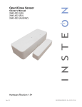
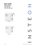
On/Off Module
Owner’s Manual
2633-422 (France)
2633-432 (Germany)
2633-442 (UK)
2633-452 (Chile)
2633-522 (AUS/NZ)
Page 1 of 14
2633-432 (Germany)
2633-452 (Chile)
2633-422
(France)
2633-442
(UK)
2633-522
(Aus/NZ)
Rev: 1/21/2014 7:47 AM
TABLE OF CONTENTS
About On/Off Module .................................................................................................................................. 2
Features and Benefits ............................................................................................................................... 3
Installation ................................................................................................................................................... 3
Using On/Off Module Paddle...................................................................................................................... 4
Adjust Local Settings ................................................................................................................................. 4
Change LED Brightness (or turn it off) ...................................................................................................... 4
Error Blink .................................................................................................................................................. 4
Blink on Traffic ........................................................................................................................................... 4
Beep on Button Press ................................................................................................................................ 5
INSTEON Setup ........................................................................................................................................... 5
INSTEON Controllers, Responders and Links .......................................................................................... 5
Configure INSTEON Settings .................................................................................................................... 5
Make On/Off Module a Responder ............................................................................................................ 5
Make On/Off Module a Controller .............................................................................................................. 6
Groups ....................................................................................................................................................... 6
Scenes ....................................................................................................................................................... 6
Make On/Off Module a Controller of Multiple Responders ........................................................................ 7
Remove On/Off Module as a Controller .................................................................................................... 7
Remove On/Off Module as a Responder .................................................................................................. 7
Remove On/Off Module as a Controller of Multiple Responders .............................................................. 8
Factory Reset ............................................................................................................................................ 8
X10 Setup ..................................................................................................................................................... 8
Add X10 Address ....................................................................................................................................... 8
Remove X10 Address ................................................................................................................................ 8
Specifications .............................................................................................................................................. 9
All product specifications are subject to change. ................................................................................. 11
Troubleshooting ........................................................................................................................................ 11
Phase Bridge Detect Beacon/RF Range Test ......................................................................................... 12
Certification and Warranty ....................................................................................................................... 13
DECLARATION OF CONFORMITY ........................................................................................................ 13
Limited Warranty ..................................................................................................................................... 14
About On/Off Module
INSTEON On/Off Module makes adding customizable INSTEON (and X10) remote control to your lamps
and appliances as easy as plug and play. It’s home automation at its simplest and most convenient.
LED
Paddle top
(on)
Paddle bottom
(off)
Page 2 of 14
Rev: 1/21/2014 7:47 AM
Set button
Features and Benefits
-
Integrated on/off relay
Compatible with all INSTEON (and X10) controllers; can also act as an INSTEON (and X10)
controller
Super-easy setup with multi-color LED and beeper
Dual-band communicates simultaneously over both RF and powerline
Stores setup state in non-volatile memory so settings aren’t lost during power outages
Two-year warranty
Installation
CAUTIONS AND WARNINGS
Read and understand these instructions before installing and retain them for future reference.
This product is not designed or approved for use on powerlines other than 100-240VAC,50Hz or 60Hz, single phase. Attempting to
use this product on non-approved powerlines may have hazardous consequences.
-
Use only indoors or in outdoor rated box
This product may feel warm during operation. The amount of heat generated is within approved limits and poses no hazards.
To minimize heat buildup, ensure the area surrounding this product is as clear of clutter as possible.
Each INSTEON product is assigned a unique INSTEON I.D., which is printed on the product’s label.
To reduce the risk of overheating and possible damage to other equipment, do not use this product to control loads in excess
of the specified maximum(s) or, install in locations with electricity specifications which are outside of the product’s
specifications. If this device supports dimming, please note that dimming an inductive load, such as a fan or transformer,
could cause damage to the dimmer, the load bearing device, or both. If the manufacturer of the load device does not
recommend dimming, use a non-dimming INSTEON on/off switch. USER ASSUMES ALL RISKS ASSOCIATED WITH
DIMMING AN INDUCTIVE LOAD.
IMPORTANT!
If you have any difficulties or questions, consult an electrician. If you are not knowledgeable about, and comfortable with, electrical
circuitry, you should have a qualified electrician install the product for you.
In the Box
On/Off Module
Quick Start Guide
Tools Needed
None
1) Turn on lamp or appliance
2) Unplug lamp/appliance and plug it into On/Off Module receptacle
3) Plug On/Off Module into unswitched wall outlet
Load will turn on
On/Off Module LED will turn green
Page 3 of 14
Rev: 1/21/2014 7:47 AM
Optional Accessories
INSTEON Hub
Mini Remote
Using On/Off Module Paddle
On/Off Module’s paddle will control the load and any additional linked responders with tap, double-tap and press and
hold actions to initiate different behaviors.
On/Off Module Paddle
Tap
Press and hold
Top
On
until release or 100%
(dimmable responders only)
Bottom
Off
until release or off
(dimmable responders only)
Double-tap
LED
Instant full-on
Green
Instant full-off
Red
Brighten
Dim
Adjust Local Settings
Change LED Brightness (or turn it off)
Default = 50% brightness level
1) Press and hold On/Off Module set button until it beeps
LED will start blinking green
2) Press and hold On/Off Module set button until it beeps a second time
LED will start blinking red
3) Press and hold On/Off Module set button until it beeps a third time
LED will start blinking green
4) Tap On/Off Module set button once
LED starts double-blinking green
5) Press and hold On/Off Module set button until it beeps
LED will turn green (at brightness of connected load)
6) Use the On/Off Module’s paddle to brighten or dim LED to desired brightness
7) Tap On/Off Module set button to accept
On/Off Module will double-beep and return to ready mode
Error Blink
Default = enabled
This setting is only adjustable via software or a central controller. On/Off Module LED will blink red once if
one or more responders do not acknowledge a message and will blink green once if all responders are
successful.
Blink on Traffic
Default = disabled
This setting is only adjustable via software or a central controller. DIN Rail module LED will blink red if it
detects noise that could disrupt communication.
Page 4 of 14
Rev: 1/21/2014 7:47 AM
Beep on Button Press
Default = disabled
This setting is only adjustable via software or a central controller. On/Off Module will beep every time its
paddle is tapped.
INSTEON Setup
Some products have subtle differences in their setup procedures. Please refer to the other devices’
owner’s manuals for details.
INSTEON Controllers, Responders and Links
Let’s define a few terms.
•
The INSTEON “transmitter” is called a controller
•
The INSTEON “receiver” is called a responder
•
The association between the controller and responder is called a link
Link
Controller
Responder
Note that a link is one way. If you wish to have control “the other way,” simply add a link “the other way.”
Configure INSTEON Settings
Most On/Off Module links and settings can be configured locally—during installation with the module’s set
button or after installation using the switch connected to the module—or remotely via software (sold
separately).
All On/Off Module settings can be managed remotely via software (sold separately).
Make On/Off Module a Responder
1) Press and hold controller set button until it beeps
Controller LED will start blinking green
You will have four minutes to complete the next steps before linking mode times out
2) Turn on load connected to On/Off Module and adjust to desired level (on or off)
3) Press and hold On/Off Module set button until it double-beeps
Controller will double-beep and its LED will stop blinking
4) Test link by tapping controller button on and off or pressing and holding to brighten/dim
Load connected to On/Off Module will respond appropriately
Note:
-
The link just created is one way. See Make On/Off Module a Controller or Groups to add another
link to keep the two products in sync.
-
If you wish the load to be off when link is activated—such as for an “all off” scene—turn off the
load in step #2.
Page 5 of 14
Rev: 1/21/2014 7:47 AM
Make On/Off Module a Controller
1) Press and hold On/Off Module set button until it beeps
On/Off Module LED will start blinking green
You will have four minutes to complete the next steps before linking mode times out
2) Adjust responder to desired state
3) Press and hold responder set button until it double-beeps
1
On/Off Module will double-beep and its LED will stop blinking
4) Test link by tapping or pressing and holding On/Off Module paddle to turn on/off or brighten/dim
Responder will respond appropriately
Note:
-
The link just created is one way. See Make On/Off Module a Responder or Groups to add
another link to keep the two products in sync.
-
If you wish the load to be off when link is activated—such as for an “all off” scene—turn off the
load in step #2.
Groups
Devices in a group share all the same settings (e.g., on-level, ramp rate). This keeps all group members
synchronized. Every device in a group is both a controller of, and responder to, all the other devices. The
most common example of a group is a 3-way lighting circuit (2 switches). For simplicity, we will assume
that the desired group level is on.
The following steps will create a virtual 3-way circuit including device “A” and device “B”:
Turn A and B on
Press and hold A set button until it beeps
A status LED will start blinking green
3) Press and hold B set button until it double-beeps
A will double-beep and its LED will stop blinking
4) Press and hold B set button until it beeps
B LED will start blinking green
5) Press and hold A set button until it double-beeps
B will double-beep and its LED will stop blinking
6) Test by turning load on and off from A and then B
The load(s) and both A and B LEDs will remain in synch
1)
2)
Scenes
Devices in a scene can each have different settings. This provides for advanced scene creation. Software
is recommended for scene management.
Example of a scene with 1 controller and On/Off Module as a member:
1) Press and hold controller set button until it beeps
Controller LED will start blinking green
2) Tap controller set button
Controller LED will start double-blinking green
1
If either controller or responder LED continues blinking, the addition failed. Tap device’s set button until LED stops blinking and try linking again.
Page 6 of 14
Rev: 1/21/2014 7:47 AM
3) Adjust On/Off Module to desired level (on or off)
4) Press and hold On/Off Module set button until it double-beeps
5) For each additional scene member:
a) Adjust member to desired scene brightness
b) Press and hold set button until it double-beeps
6) Tap controller set button
Controller will beep and LED will stop blinking
7) Test by tapping controller button on and off
On/Off Module and other scene responders will all respond appropriately
Make On/Off Module a Controller of Multiple Responders
1) Press and hold On/Off Module set button until it beeps
LED will start blinking green
2) Tap On/Off Module set button
LED will start double-blinking green
3) For each responder you are adding:
a) Adjust responder to desired scene brightness/state
b) Press and hold set button until it double-beeps
4) Tap On/Off Module set button
On/Off Module will beep and LED will stop blinking
5) Test by tapping On/Off Module paddle on and off
All the responders will turn on and off
Remove On/Off Module as a Controller
If you no longer want On/Off Module to control another device (or are removing On/Off Module from your
network) it is important that you follow the instructions below for each responder.
1) Press and hold On/Off Module set button until it beeps
LED will start blinking green
2) Press and hold On/Off Module set button until it beeps a second time
LED will start blinking red
3) Press and hold responder set button until it double-beeps
On/Off Module will double-beep and LED will stop blinking
4) Test by tapping On/Off Module on and off
Former responder will not respond
Remove On/Off Module as a Responder
If you no longer want a controller button to control On/Off Module, follow these directions.
Note: If you ever wish to uninstall On/Off Module, it is important that you remove all On/Off Module
responder links. Otherwise, controllers will repetitively retry commands, creating network delays.
1) Press and hold controller button until it beeps
LED will start blinking green
2) Press and hold controller button until it beeps a second time
LED will start blinking red
3) Press and hold On/Off Module set button until it double-beeps
Controller LED will stop blinking
4) Test by tapping controller button on and off
On/Off Module will no longer respond
Page 7 of 14
Rev: 1/21/2014 7:47 AM
Remove On/Off Module as a Controller of Multiple Responders
1) Press and hold On/Off Module set button until it beeps
LED will start blinking green
2) Press and hold On/Off Module set button until it beeps a second time
LED will start blinking red
3) Tap On/Off Module set button
LED will start double-blinking red
4) For each responder you are removing:
a. Press and hold set button until it double-beeps
5) Tap On/Off Module set button
On/Off Module will beep and LED will stop blinking
6) Test by tapping On/Off Module paddle on and off
None of the former responders will respond
Factory Reset
All settings, links and scenes will be erased.
1) Press and hold On/Off Module set button until it beeps
LED will start blinking green
2) Press and hold On/Off Module set button until it beeps a second time
LED will start blinking red
3) Press and hold On/Off Module set button until it beeps a third time
LED will start blinking green
4) Slowly tap On/Off Module set button 3 times
LED will start double-blinking green
5) Press and hold On/Off Module set button. Do not let go.
On/Off Module will begin to emit a long beep
6) After beep stops, release On/Off Module set button
After a few seconds, On/Off Module will double-beep
X10 Setup
On/Off Module ships with no X10 address assigned.
Add X10 Address
1) Press and hold set button until it beeps
LED will start blinking green
2) Send the X10 address 3 times (with or without commands)
Example: A1-AON-A1-AON-A1-AON or A1-A1-A1-AON
On/Off Module will double-beep and LED will stop blinking
3) Test by sending X10 on and off commands
Load will turn on and off
Remove X10 Address
1) Press and hold set button until it beeps
LED will start blinking green
2) Press and hold set button until it beeps a second time
LED will start blinking red
3) Send the X10 address 3 times (with or without commands)
Page 8 of 14
Rev: 1/21/2014 7:47 AM
Example: A1-OFF-A1-OFF-A1-OFF or A1-A1-A1-AOFF
On/Off Module will double-beep and LED will stop blinking
4) Test by sending X10 on and off commands
On/Off Module will not respond
Specifications
General
Product name
On/Off Module
Brand/manufacturer
INSTEON
Manufacturer product number
2633-422 France
2633-432 Germany
2633-442 UK
2633-452 Chile
2633-522 AUS/NZ
UPC
813922012651 France
813922012668 Germany
813922012675 UK
813922014112 Chile
813922012682 AUS/NZ
Warranty
2 years, limited
INSTEON
INSTEON powerline mesh repeater
Yes
INSTEON RF mesh repeater
Yes
INSTEON controller
Yes
INSTEON responder
Yes
Maximum links/scenes
400
Green when load is on, red when load is off
Blinks green once when all responders acknowledge (can be
disabled via software)
LED
Blinks red once if responder does not acknowledge
Blinks red or green during setup
Blinks red to indicate traffic (must be enabled via software)
Beep on button press
Beeps when button is pressed (must be enabled via software)
LED brightness
Adjustable, from off to bright
Local control
Yes
Commands supported as controller
Page 9 of 14
On
Off
Fast-on
Fast-off
Begin brighten
Begin dim
End brighten
End dim
Rev: 1/21/2014 7:47 AM
Commands supported as responder
On
Off
Fast-on
Fast-off
Beep
Software configurable
Yes
RF range
Up to 50 meters (150 feet) open air
Phase bridge detect beacon
Yes
INSTEON device category
0x02 appliance control
INSTEON device subcategory
2633-422 (France, 869.85 MHz)
2633-432 (Germany, 869.85 MHz)
2633-442 (UK, 869.85 MHz)
2633-452 (Chile, 915 MHz)
2633-522 (Aus/NZ, 921.0 MHz)
X10
X10 address
1 optional (comes unassigned)
X10 transmitter
Yes
X10 receiver
Yes
X10 status response
Supported
X10 minimum transmit level
3.2 Vpp into 5 Ohms
X10 minimum receive level
20mV into 5 Ohms
X10 messages repeated
Mechanical
No
Mounting
AC outlet
Wires
Screw clamp connections
N/A
N/A
Case color
White
Set button
1
Plastic
UV stabilized polycarbonate
Beeper
Yes
LED
1, RGB
Dimensions
10cm H x 4.3cm W x 3.4cm D - France
10cm H x 4.3cm W x 3.4cm D - Germany
10.4cm H x 5cm W x 3.5cm D - UK
10cm H x 4.3cm W x 3.4cm D - Chile
10.8cm H x 4.3cm W x 3.5cm D - AUS/NZ
Weight
130g ±10g
Operating environment
Indoors
Operating temperature range
0 to 40 C / 32 to 104 F
Operating humidity range
0-90% relative humidity
Storage temperature range
-20 to 70 C / -4 to 158 F
Page 10 of 14
o
o
o
o
o
o
o
Rev: 1/21/2014 7:47 AM
o
0x2D
0x30
0x35
0x3A
0x36
Electrical
Voltage
100VAC to 240VAC (+/- 10%)
Frequency
50/60Hz auto detected at power-up
16A – 240VAC (EUR)
10A – 240VAC (AUS/NZ)
Maximum load
3600W/240VAC Resistive
700W/240VAC Inductive/Capacitive
2000W/240VAC Bulbs/Low Voltage Halogen
Minimum load
N/A
Resistive
Load type(s)
Inductive/capacitive
Low voltage halogen
Hardwired remote control
N/A
Retains all settings without power
Yes, saved in non-volatile EEPROM
Standby power consumption
< 0.75 watts
Safety approved
CE, C-Tick
EN 300 220-2, 301 489-3
Certifications
AS/NZS 4268, CISPR 22
IEC 60669-2-1
All product specifications are subject to change.
Troubleshooting
Problem
Possible Cause
Solution
On/Off Module LED is not turning
on
On/Off Module is not
getting power
Make sure On/Off Module is not
plugged into a switched outlet that is
turned off
Powerline signals can’t travel through
On/Off Module or the
some power filters. Plug On/Off
controller is plugged into a
Module or controller into an
power strip or AC line filter
unswitched wall outlet.
On/Off Module won’t add to a
scene as a controller or responder
Page 11 of 14
The INSTEON signal may
be too weak
Add additional INSTEON devices or
move around existing INSTEON
Large appliances, such as devices. All INSTEON devices act as
INSTEON network repeaters.
refrigerators or air
conditioners, may be
producing electrical noise
on the powerline.
Rev: 1/21/2014 7:47 AM
Other electrical devices,
such as computers,
televisions or power strips,
may be absorbing the
INSTEON signal
The controller may be
sending commands to a
responder that is no
On/Off Module is taking a long time
longer in use. Commands
to respond to a controller
for the unused responder
are being resent and
slowing down the network
Remove from the scene any unused
responders from the controller. (HINT:
If you are using home automation
software, you can easily check scene
membership and eliminate
unnecessary memberships.)
If the above doesn’t work, perform a
factory reset on the controller
Remove from a scene any unused
responders from On/Off Module.
(HINT: If you are using home
automation software, you can easily
check scene membership and
eliminate unnecessary responders.)
If the above doesn’t work, perform a
factory reset on On/Off Module. See
Factory Reset.
Responders are taking a long time
to respond to On/Off Module
On/Off Module may be
sending commands to a
responder that is no
longer in use. Commands
for the unused responder
are being resent and
slowing down the network
The load turned on by itself
Another controller, a timer
or stray X10 signals could
have triggered On/Off
Module
Perform a factory reset on On/Off
Module. See Factory Reset.
On/Off Module can turn off a
responder, but nothing happens
when I send an on command from
On/Off Module
The responder may be
added to the scene at its
off state
Add the device to a scene as a
responder to On/Off Module, while the
responder’s load is on. See the
responder’s Owner’s Manual for more
detailed scene adding instructions.
The controller can turn off On/Off
Module, but On/Off Module does
not turn on when I send an on
command from the controller
On/Off Module may be
added to a scene at its off
state
Re-add On/Off Module to a scene as
a controller while the load is on. See
Make On/Off Module a Controller.
On/Off Module is locked up
A surge or excessive
noise on the powerline
may have locked it up
Unplug On/Off Module for 10 seconds
and then reinstall
If the above doesn’t work, perform a
factory reset. See Factory Reset.
The load does not turn on when I
manually activate the load’s built-in
switch
On/Off Module may be off
Turn on On/Off Module using the
paddle on the side of the module
Bulb may be burnt out
Replace the lamp’s bulb
The load is not being controlled by
On/Off Module
The load may not be
getting power
Make sure the load’s built-in switch is
in the on position
Phase Bridge Detect Beacon/RF Range Test
Dimmer module automatically bridges the electrical phases in your home (via communications with other
dual-band devices on the “other phase”). This is only important in 2-phase homes with powerline-only
Page 12 of 14
Rev: 1/21/2014 7:47 AM
INSTEON products or buildings with both 2- and 3- phase circuits. The phase bridge detect beacon can
also be used as an RF range test to see if your devices are within communication range. You will need at
least one other INSTEON dual-band device installed.
1) Press and hold set button until it beeps
LED will start blinking green
2) Press and hold set button until it beeps a second time
LED will start blinking red
3) Press and hold set button until it beeps a third time
LED will start blinking green
4) Slowly tap set button 2 times
LED will continue blinking green
5) Press and hold set button until it beeps
Micro module will start beeping once per second
LED will turn solid green
6) Check the LED behavior of other dual-band devices
Phase Bridge Detect Beacon
•
If the other dual-band device is blinking green, it is on the other phase:
Device provides a phase bridge to Dimmer module
•
If the other dual-band device is blinking red, it is on the same phase:
Device does not provide a phase bridge to Dimmer module
Relocate if necessary (and practical)
•
If the other dual-band device is not blinking:
Device is not within RF range of Dimmer module so it does not provide a phase bridge
Relocate if necessary (and practical) or add an additional dual-band device
RF Range Test
•
If LED is blinking:
Device is within RF communication range
•
If LED is not blinking:
Device is not within RF communication range
Relocate if necessary (and practical) or add an additional dual-band device
7) Tap set button
Dimmer module will stop beeping
Other device LEDs will stop blinking
If you have tried these solutions, reviewed the owner's manual, and still cannot resolve an issue, visit
http://www.insteon.com/support or call INSTEON Support Line at 866-243-8022.
Certification and Warranty
DECLARATION OF CONFORMITY
Hereby, INSTEON declares that this device is in compliance with the essential requirements and other relevant provisions of the following Directives:
1) Low Voltage Equipment Directive 2006/95/EC
2) Electromagnetic Compatibility Directive 2004/108/EC
3) Hazardous Substance Directive 2005/95/EC
Technical data and copies of the original Declaration of Conformity are available and can be obtained from INSTEON; 16542 Millikan Ave, Irvine, CA,
USA.
User Information for Consumer Products Covered by EU Directive 2002/96/EC on Waste Electric and Electronic Equipment (WEEE)
This document contains important information for users with regards to the proper disposal and recycling of INSTEON products. Consumers are
required to comply with this notice for all electronic products bearing the following symbol:
Environmental Information for Customers in the European Union
Page 13 of 14
Rev: 1/21/2014 7:47 AM
European Directive 2002/96/EC requires that the equipment bearing this symbol on the product and/or its packaging must not be disposed of with
unsorted municipal waste. The symbol indicates that this product should be disposed of separately from regular household waste streams.
It is your responsibility to dispose of this and other electric and electronic equipment via designated collection facilities appointed by the government or
local authorities. Correct disposal and recycling will help prevent potential negative consequences to the environment and human health.
For more detailed information about the disposal of your old equipment, please contact your local authorities, waste disposal service, or the shop
where you purchased the product.
DECLARATION OF CONFORMITY TO R&TTE DIRECTIVE 1999/5/EC for the European Community, Switzerland, Norway, Iceland and Liechtenstein
Product category: general consumer (category 3).
English: This equipment is in compliance with the essential requirements and other relevant provisions of the European R&TTE Directive 1999/5/EC
Deutsch [German]: Dieses Gerät entspricht den grundlegenden Anforderungen und den weiteren entsprechenden Vorgaben der Richtlinie 1999/5/EU.
Nederlands [Dutch]: Dit apparaat voldoet aan de essentiele eisen en andere van toepassing zijnde bepalingen van de Richtlijn 1999/5/EC.
Svenska [Swedish]: Denna utrustning står I överensstämmelse med de väsentliga egenskapskrav och övriga relevanta bestämmelser som framgår av
direktiv 1999/5/EG.
Français [French]: Cet appareil est conforme aux exigences essentielles et aux autres dispositions pertinentes de la Directive 1999/5/EC
Español [Spanish]: Este equipo cumple con los requisitos esenciales asi como con otras disposiciones de la Directiva 1999/5/CE.
Português [Portuguese]: Este equipamento está em conformidade com os requisitos essenciais e outras provisões relevantes da Directiva 1999/5/EC.
Italiano [Italian]: Questo apparato é conforme ai requisiti essenziali ed agli altri principi sanciti dalla Direttiva 1999/5/CE.
Norsk [Norwegian]: Dette utstyret er i samsvar med de grunnleggende krav og andre relevante bestemmelser i EU-direktiv 1999/5/EF.
Suomi [Finnish]:Tämä laite tÿttää direktiivin 1999/5/EY olennaiset vaatimukset ja on siinä asetettujen muiden laitetta koskevien määräysten mukainen.
Dansk [Danish]: Dette udstyr er i overensstemmelse med de væsentlige krav og andre relevante bestemmelser i Direktiv 1999/5/EF.
Polski [Polish]: Urządzenie jest zgodne z ogólnymi wymaganiami oraz szczególnymi warunkami okreslonymi Dyrektywą UE: 1999/5/EC
In 2002, the European Union introduced the Directive on Waste Electrical and Electronic Equipment (WEEE). The main
aim of the Directive is to ensure that WEEE is collected and treated separately. WEEE may contain hazardous substances
that should not end-up in the (human) environment because it can have adverse effects on it.Furthermore, WEEE is a vast
source of raw materials. With the ever-rising worldwide demand for new equipment and the ever-decreasing volume of raw
materials in nature, letting this potential source of such materials go to waste is unacceptable. If equipment is collected
separately, the equipment can be recycled and up to 85 to 90% of the equipment can be reused as new material, saving
the use of virgin raw materials and energy of producing these. Separate collection and treatment of WEEE will thus
decrease CO2 emissions as well. For the above reasons, INSTEON expects end-users to dispose of the material in an
environmentally friendly way through separate collection and treatment. Electrical and Electronic Equipment is labeled with
the following 'crossed out wheeled bin' symbol indicating that the equipment should be disposed of, by the end-user,
separate from other types of waste. End-users should contact their dealer/distributor or our company on disposal,
collection and recycling options in their country.
Limited Warranty
Seller warrants to the original consumer purchaser of this product that, for a period of two years from the date of purchase, this product will be free
from defects in material and workmanship and will perform in substantial conformity to the description of the product in this Owner’s Manual. This
warranty shall not apply to defects or errors caused by misuse or neglect. If the product is found to be defective in material or workmanship, or if the
product does not perform as warranted above during the warranty period, Seller will either repair it, replace it, or refund the purchase price, at its
option, upon receipt of the product at the address below, postage prepaid, with proof of the date of purchase and an explanation of the defect or error.
The repair, replacement, or refund that is provided for above shall be the full extent of Seller’s liability with respect to this product. For repair or
replacement during the warranty period, call 866-243-8022 with the Model # and Revision # of the device to receive an RMA# and send the product,
along with all other required materials to:
INSTEON
ATTN: Receiving
16542 Millikan Ave.
Irvine, CA 92606-5027
Limitations
The above warranty is in lieu of and Seller disclaims all other warranties, whether oral or written, express or implied, including any warranty or
merchantability or fitness for a particular purpose. Any implied warranty, including any warranty of merchantability or fitness for a particular purpose,
which may not be disclaimed or supplanted as provided above shall be limited to the two-year of the express warranty above. No other representation
or claim of any nature by any person shall be binding upon Seller or modify the terms of the above warranty and disclaimer.
Home automation devices have the risk of failure to operate, incorrect operation, or electrical or mechanical tampering. For optimal use, manually verify
the device state. Any home automation device should be viewed as a convenience, but not as a sole method for controlling your home.
In no event shall Seller be liable for special, incidental, consequential, or other damages resulting from possession or use of this device, including
without limitation damage to property and, to the extent permitted by law, personal injury, even if Seller knew or should have known of the possibility of
such damages. Some states do not allow limitations on how long an implied warranty lasts and/or the exclusion or limitation of damages, in which case
the above limitations and/or exclusions may not apply to you. You may also have other legal rights that may vary from state to state.
Protected under U.S. and foreign patents (see www.insteon.com)
© Copyright 2013 INSTEON, 16542 Millikan Ave., Irvine, CA 92606, 866-243-8022, www.insteon.com
Page 14 of 14
Rev: 1/21/2014 7:47 AM