1
P0011-P0088-E.qxd
08.11.6 1:43 PM
Page 73
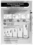
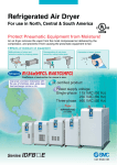
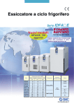
Refrigerated Air Dryer
Series IDFB 쏔E
For use in North, Central & South America
HAA
HAW
UL certified product
AT
Power supply voltage:
Single-phase 115 VAC (60 Hz)
230 VAC (60 Hz)
Refrigerant
R134a(HFC)
IDF
IDU
Coefficient of destruction IDFA
for ozone is zero.
IDFB
Improved corrosion resistance with
the use of stainless steel, plate type
heat exchanger (IDFB4E to 37E)
ID
IDG
AMG
AFF
AM
AMD
AMH
AME
AMF
SF
SFD
LLB
AD쏔
GD
Air flow capacity SCFM (m3/h (ANR))
Model
Outlet air pressure dew point
Refrigerant
Rated inlet condition
Port size
37°F (2.8°C)
45°F (7.2°C)
50°F (10°C)
IDFB3E
10 (17)
11 (19)
12 (20)
NPT 3/8
IDFB4E
15 (25)
16 (27)
17 (28)
NPT 1/2
IDFB6E
25 (43)
26 (45)
28 (47)
IDFB8E
41 (70)
43 (74)
45 (77)
IDFB11E
59 (100)
62 (106)
65 (110)
IDFB15E
71 (120)
80 (136)
86 (147)
IDFB22E
107 (182)
120 (205)
130 (221)
IDFB37E
161 (273)
173 (294)
181 (308)
R134a (HFC)
100°F (37.8°C)
100 psi (0.7 MPa)
NPT 3/4
NPT 1
NPT 1 1/2
IDFB55E and IDFB75E are also available. Contact SMC for details.
73
P0011-P0088-E.qxd
08.11.6 1:43 PM
Page 74
INDEX
1. Standard Products
Model
Series IDFB
Standard inlet air type
Rated inlet air temperature:
100°F (37.8°C)
Air flow capacity SCFM (m3/h [ANR])
Outlet air pressure dew point
Rated inlet
condition
Refrigerant
37°F (2.8°C) 45°F (7.2°C) 50°F (10°C)
IDFB3E
IDFB4E
IDFB6E
IDFB8E
IDFB11E
IDFB15E
IDFB22E
IDFB37E
10 (17)
11 (19)
12 (20)
NPT 3/8
15 (25)
16 (27)
17 (28)
NPT 1/2
25 (43)
26 (45)
28 (47)
41 (70)
43 (74)
45 (77)
59 (100)
62 (106)
65 (110)
R134a
(HFC)
71 (120)
80 (136)
86 (147)
107 (182)
120 (205)
130 (221)
161 (273)
173 (294)
181 (308)
NPT 3/4
100°F (37.8°C)
100 psig (0.7 MPa)
NPT 1
NPT 1 1/2
IDFB55E and IDFB75E are also available. Contact SMC for details.
2. Options
Applicable model
Model
(Suffix: Option symbol)
Cool compressed air output
IDFB3E to 11E
IDFB쏔E-11-A
For medium air pressure (up to 240 psi (1.6 MPa))
(Auto drain bowl: Metal bowl with level gauge)
IDFB6E to 37E
IDFB쏔E-쏔-K
With circuit breaker
With terminal block for power supply, run & alarm
signal and remote operation
IDFB4E to 37E
IDFB쏔E-쏔-R
IDFB4E to 37E
IDFB쏔E-쏔-T
Timer type solenoid valve with auto drain
(Suitable for medium air pressure)
IDFB4E to 37E
IDFB쏔E-쏔-V
Optional specifications
3. Accessory (Option)
Description
Dust-protecting filter set
74
Page
P. 82
Port size
Page
P. 80, 81
Page
P. 76 to 79
P0011-P0088-E.qxd
08.11.6 1:43 PM
Page 75
Series IDFB 쏔E
Model Selection
The corrected air flow capacity, which considers the user’s operating conditions, is required for selecting
the air dryer. Please select using the following procedures.
IDFB쏔E Selection Example
1
Data symbol Correction factor Note)
Condition
Read the correction factor.
Obtain the correction factor A to D suitable for your operating
condition using the table below.
Inlet air temperature
110°F (43°C)
A
0.82
Ambient temperature
105°F (40.5°C)
B
0.98
Inlet air pressure
75 psi (0.53 MPa)
C
0.95
Air consumption
14 SCFM
—
—
HAA
HAW
AT
Note) Values obtained from the table below.
2
Calculate the corrected air flow capacity.
Obtain the corrected air flow capacity from the following formula.
Corrected air flow capacity = Air consumption ÷ (Correction
factor A x B x C)
3
IDF
IDU
IDFA
Corrected air flow capacity = 14 SCFM ÷ (0.82 x 0.98 x 0.95)
= 18 SCFM
IDFB
ID
Select the model.
Select the model which air flow capacity exceeds the corrected
air flow capacity using the specification table. (For air flow
capacity, refer to the data D below.)
According to the corrected air flow capacity of 18 SCFM, the IDFB6E will
be selected because its air flow capacity at 60 Hz is 25 SCFM.
IDG
AMG
4
Option
Refer to pages 80 and 81.
AFF
5
Finalize the model number.
Refer to page 76.
AM
6
Select accessories sold separately.
Refer to page 82.
AMD
AMH
AME
Data A: Inlet Air Temperature
Inlet air
temperature
Ambient temperature
Correction
factor
°F
°C
90
100
110
120
32
37.8
43
49
Data B: Ambient Temperature
1.31
1.00
0.82
0.66
°F
°C
77
90
95
100
105
110
25
32
35
37.8
40.5
43
Data C: Inlet Air Pressure
Inlet air pressure
psig
MPa
Correction
factor
75
100
110
120
125
150
175
200
250
1.24
1.09
1.04
1.00
0.98
0.95
0.53
0.70
0.76
0.83
0.86
1.03
1.21
1.38
1.72
AMF
Correction
factor
SF
0.95
SFD
1.00
1.04
LLB
1.07
1.09
AD쏔
1.13
1.18
GD
1.22
1.24
Data D: Air Flow Capacity
Model
37°F (2.8°C)
Outlet air pressure
45°F (7.2°C)
dew point
50°F (10°C)
Air flow capacity SCFM (m3/h (ANR))
IDFB3E
IDFB4E
IDFB6E
IDFB8E
IDFB11E
IDFB15E
IDFB22E
IDFB37E
10 (17)
15 (25)
25 (43)
41 (70)
59 (100)
71 (120)
107 (182)
161 (273)
11 (19)
16 (27)
26 (45)
43 (74)
62 (106)
80 (136)
120 (205)
173 (294)
12 (20)
17 (28)
28 (47)
45 (77)
65 (110)
86 (147)
130 (221)
181 (308)
Note) In case of “Option A (Cool compressed air output)”, the air flow capacity is different. Refer to page 80 for details.
75
P0011-P0088-E.qxd
08.11.6 1:43 PM
Page 76
Refrigerant R134a (HFC)
Standard Inlet Air
Series IDFB 쏔E
3E, 4E, 6E, 8E, 11E, 15E, 22E, 37E
(Inlet air temperature: 100°F [37.8°C])
How to Order
IDFB 11 E
11 N
Size
Size
3
4
6
8
11
15
22
37
Nil
A
K
R
T
V
Voltage
Applicable size
Symbol
Voltage
22
37
11
Single-phase
115 VAC (60 Hz)
쎲 쎲 쎲 쎲 쎲 쎲 쎲
—
23
Single-phase
230 VAC (60 Hz)
—
3
4
6
—
—
8
—
11
—
15
—
쎲 쎲
Thread type
Size
3 to 15
22, 37
Thread type
Symbol
N
Nil
N
Nil
Drain tube size
NPT (female)
3/8
Rc (female) Note)
ø0.4 in [ø10 mm]
NPT (Male)
3/8
R (Male)
ø0.4 in [ø10 mm]
Note) For the models with sizes 3 to 15, an adopter for converting
NPT to Rc is included if the thread symbol is “Nil”.
Table of Options and Available Combinations (Size/Option)
Symbol Note 1)
Optional
specifications
Nil
A
Cool
None compressed
air output
K
For medium air pressure
Auto drain bowl:
Metal case with level gauge
R
With
circuit
breaker
Size
3
4
6
8
11
15
22
37
쎲
쎲
쎲
쎲
쎲
쎲
쎲
쎲
쎲
쎲
쎲
쎲
쎲
—
—
—
V
Timer type
solenoid valve
With terminal
with auto drain
block for run
(Suitable for
& alarm signal
medium air
pressure)
—
—
—
—
—
쎲
쎲
쎲
쎲
쎲
쎲
쎲
쎲
쎲
쎲
쎲
쎲
쎲
쎲
쎲
쎲
쎲
쎲
쎲
쎲
쎲
쎲
쎲
쎲
쎲
쎲
쎲
Note 1) Enter alphabetically when multiple options are combined.
However, the following combination cannot be achieved.
• Combination of K and V (Only one or the other may be attached.)
Note 2) Refer to pages 80 and 81 for further information on options.
76
T
P0011-P0088-E.qxd
08.11.6 1:43 PM
Page 77
Refrigerated Air Dryer
Series IDFB 쏔E
Standard Specifications
Model
Operating
ranges
Rated
conditions
IDFB4E
IDFB6E
IDFB8E
IDFB11E
IDFB15E
IDFB22E
IDFB37E
Compressed air
Fluid
°F (°C)
Inlet air temperature
41 to 122 (5 to 50)
22 (0.15) to 150 (1.0)
psi (MPa)
Inlet air pressure
Ambient temperature
Air flow
Outlet air pressure dew point
capacity
Outlet air pressure dew point
SCFM
(m3/h (ANR)) Outlet air pressure dew point
Electric
specifications
Standard inlet air
IDFB3E
Specifications
°F (°C)
37°F (2.8°C)
10 (17)
15 (25)
25 (43)
41 (70)
59 (100)
71 (120)
107 (182)
161 (273)
45°F (7.2°C)
11 (19)
16 (27)
26 (45)
43 (74)
62 (106)
80 (136)
120 (205)
173 (294)
50°F (10°C)
12 (20)
17 (28)
28 (47)
45 (77)
65 (110)
100 (0.7)
86 (147)
130 (221)
181 (308)
36 to 104 (2 to 40) Relative humidity of 85% or less
psi (MPa)
Operating pressure
Inlet air temperature
°F (°C)
100 (37.8)
Ambient temperature
°F (°C)
100 (37.8)
Operating current
(A)
2.7
3.0
3.0
3.5
Power consumption
(W)
240
260
260
310
Applicable circuit breaker capacity (A)
6.5
7.5
550
750
Forced air-cooled
Refrigerant
R134a (HFC)
Symbol N
Drain tube O.D.
IDF
IDU
9
4.5
1000
IDFB
5.6
ID
1270
15
Condenser
Thread symbol and size
AT
IDFA
Single-phase 230 VAC
[voltage fluctuation ±10%] 60 Hz
Single-phase 115 VAC [voltage fluctuation ±10%] 60 Hz
Power supply voltage
HAA
HAW
NPT 3/8 (female) NPT 1/2 (female)
Rc 3/8 (female)
Rc 1/2 (female)
Symbol Nil
With Rc
With Rc
conversion adapter conversion adapter
Symbol N
IDG
NPT 3/4 (female)
NPT 1 (female) NPT 1 (Male) NPT 1 1/2 (Male)
Rc 1 (female)
R 1 (Male) R 1 1/2 (Male)
With Rc
conversion adapter
Rc 3/4 (female)
With Rc conversion adapter
AMG
AFF
3/8 inch
Symbol Nil
AM
10 mm
Coating color
White 1
lbs (kg)
Mass
40 (18)
55 (25)
57 (26)
64 (29)
Compliant standards
73 (33)
110 (50)
119 (54)
137 (62)
Note 1) ANR is under the conditions of 68°F (20°C) at atmospheric pressure and relative humidity of 65%.
Note 2) Install a circuit breaker with a sensitivity of 30 mA.
Note 3) If this equipment suffers a short-term power outage (even if it is only momentary), it may require some time before normal operation resumes, and protective mechanisms
may prevent normal operation even after the power supply has been restored.
Replacement Parts
Model
Auto drain replace- Thread symbol N
ment part no. Note) Thread symbol Nil
IDFB3E
IDFB4E
IDFB6E
IDFB8E
IDFB11E
IDFB15E
AD38N-Z
AD48N-Z
AD38
AD48
IDFB22E
IDFB37E
Body
Humid, hot air coming into the air dryer will be cooled down by a cooler∗ (heat exchanger). Water condensed at this
time will be removed from the air by a drain separator (auto drain) and drained out automatically. Air separated from
the water will be heated by a re-heater∗ (heat exchanger) to obtain the dried air, which goes through to the outlet side.
∗ IDFB22E/37E: Cooler reheater
Drain separator
Compressed air inlet
Cooler
Volume
control valve
Condenser
Fan motor
Pressure switch
Capillary tube
Heat exchanger
Drain separator
Evaporation
thermometer
Drain outlet
Capillary
tube
High pressure switch
Compressor for
refrigeration
Volume
control valve
Compressor for
refrigeration
Evaporation thermometer
Condenser
Pressure
switch
Fan motor
IDFB22E, IDFB37E
JIS Symbol
Compressed air inlet
Compressed air outlet
Evaporation thermometer
Refrigerated
air dryer
Cooler reheater
Auto drain
Ball valve
Volume control valve
Accumulator
Compressor for refrigeration
Condenser
Fan motor
AMF
LLB
AD쏔
IDFB4E, IDFB6E, IDFB8E, IDFB11E, IDFB15E GD
Compressed air outlet
Compressed air inlet
Re-heater Compressed air outlet
Drain outlet
AME
SFD
Construction Principle (Circuit for Air/Refrigerant)
IDFB3E
AMH
SF
Note 4) The part number for the auto drain components without including the body part. Body part replacement is impossible.
Auto drain
AMD
UL, CSA
Auto drain
Drain outlet
Capillary tube
Pressure switch
77
P0011-P0088-E.qxd
08.11.6 1:43 PM
Page 78
Series IDFB 쏔E
Dimensions
IDFB3E
Ventilation air outlet
B
A
Q
Ventilation
direction
E
D
Power cable outlet ø0.7 [ø17 mm]
Grommet with membrane
H
Air inlet
Illuminated switch
G
Air outlet
Evaporation thermometer
C
Ventilation
direction
L
N
K
M
Unit: inch [mm]
Port size
A
B
C
D
E
F
G
H
J
K
L
M
N
Q
3/8
8.9
[226]
16.1
[410]
18.6
[473]
2.6
[67]
4.9
[125]
12.0
[304]
1.3
[33]
2.9
[73]
1.2
[31]
1.4
[36]
6.1
[154]
0.8
[21]
13.0
[330]
0.6
[15]
IDFB3E
J
Terminal
block
Dimensions
Model
F
Ventilation
air inlet
Drain tube
(O.D.: ø0.4 [ø10 mm],
Length: 31.5 [0.8 m])
IDFB4E to IDFB11E
B
A
E
Q
Illuminated switch
Air inlet
Evaporation thermometer
Air outlet
G
Ventilation
direction
C
Ventilation air outlet
F
Ventilation
direction
4 x ø13
K
N
Power cable outlet ø0.7
[ø17 mm]
Grommet with membrane
M
Dimensions
Model
IDFB4E
Unit: inch [mm]
Port size
IDFB11E
78
3/4
B
17.8
[453]
1/2
IDFB6E
IDFB8E
A
10.6
[270]
17.9
[455]
19.1
[485]
C
D
E
19.6
[498]
22.4
[568]
F
G
H
J
K
L
M
11.1
[283]
1.2
[31]
Terminal
block
J
Drain tube
(O.D.: ø0.4 [ø10 mm],
Length: 31.5 [0.8 m])
L
D
1.7
[42]
Q
10.8
[275]
3.1
[80]
14
[355]
N
9.1
[230]
1.3
[32]
0.6
[15]
9.4
[240]
3.1
[80]
0.5
[13]
11.8
[300]
H
P0011-P0088-E.qxd
08.11.6 1:43 PM
Page 79
Series IDFB 쏔E
Refrigerated Air Dryer
Dimensions
IDFB15E
HAA
HAW
B
A
AT
E D
Q
Ventilation air outlet
Air outlet
IDF
IDU
Air inlet
IDFA
Illuminated switch
G
Evaporation thermometer
Drain separator
Ventilation
direction
Ventilation
air outlet
C
Ventilation
direction
ID
Terminal
block
F
IDFB
IDG
Drain tube
(O.D.: ø0.4 [ø10 mm],
Length: 31.5 [0.8 m])
J
AMG
L
K
4 x ø0.5
[4 x ø13]
N
Power cable outlet ø0.7 [ø17 mm]
Grommet with membrane
Dimensions
Model
AFF
H
M
Unit: inch [mm]
AM
Port size
A
B
C
D
E
F
G
H
J
K
L
M
N
Q
AMD
1
11.8
[300]
23.7
[603]
22.8
[578]
1.6
[41]
2.1
[54]
16.6
[396]
3.4
[87]
10.2
[258]
1.7
[43]
0.6
[15]
10.6
[270]
4.0
[101]
15.0
[380]
0.6
[16]
AMH
IDFB15E
AME
IDFB22E, IDFB37E
AMF
Air inlet
Port size
Air outlet
Port size
A
B
SF
E
G
D
SFD
Auto drain
LLB
Illuminated switch
AD쏔
Evaporation thermometer
Ball valve
F
GD
Ventilation direction
C
Ventilation
direction
Terminal
block
L
P
J
Drain tube
(O.D.: ø0.4 [ø10 mm],
Length: 35.4 [0.9 m])
K
N
H
M
4 x ø0.5
[4 x ø13 mm]
Power cable outlet ø0.7 [ø17 mm]
(Wire diameter ø0.4 [ø9 to ø11])
Dimensions
Model
Unit: inch [mm]
Port size
IDFB22E
1
IDFB37E
1 1/2
A
11.4
[290]
B
30.5
[775]
33.7
[855]
C
24.5
[623]
D
5.3
[134]
E
15.9
[405]
F
27.5
[698]
G
3.7
[93]
H
1.8
[46]
J
1.0
[25]
K
0.5
[13]
L
12.4
[314]
M
3.3
[85]
N
23.6
[600]
26.8
[680]
P
13.4
[340]
79
P0011-P0088-E.qxd
08.11.6 1:43 PM
Page 80
Series IDFB 쏔E
Refer to “How to
Order” page 76 for
optional models.
Optional Specifications 1
A
Option symbol
Cool compressed air output
IDFB3E to 11E
There is no heating of cooled, dehumidified air as it leaves the air dryer.
The air flow capacity with this option is smaller than that of the standard
dryer. (The external dimensions are identical with the standard product.)
Note) Perform thermal insulation treatment for pipings and equipment
installed after the dryer to prevent the formation of condensation.
R
Option symbol
With circuit breaker
IDFB4E to 37E
A circuit breaker with cover is attached to the side of the air dryer. This
saves additional electrical wiring at the time of installation.
IDFB4E to 15E
15.7 [40]
Air flow capacity (ANR)
5 SCFM 13 SCFM 17 SCFM 19 SCFM 23 SCFM
(8 m3/h) (23 m3/h) (29 m3/h) (32 m3/h) (39 m3/h)
Conditions: Inlet air pressure: 100 psi (0.7 MPa), Inlet air temperature: 100°F (37.8°C),
Outlet air temperature: 50°F (10°C), Ambient temperature: 100°F (37.8°C)
K
D
Circuit breaker
A
IDFB3E IDFB4E IDFB6E IDFB8E IDFB11E
C
Model
2.36 [60]
Air Flow Capacity
B
E
Power cable outlet (ø0.7 [ø17 mm])
Grommet with membrane
Option symbol
For medium air pressure
Auto drain bowl:
Metal bowl with level gauge
Dimensions
IDFB6E to 37E
The auto drain is changed from the standard one to one with a medium
pressure specification.
A metal bowl with a level gauge which can confirm the water level is used
for the auto drain.
Specifications
Unit: inch [mm]
Model
A
B
C
D
E
IDFB4E, 6E, 8E, 11E
1.3
[32]
9.0
[230]
3.8
[97]
1.3
[34]
0.6
[15]
IDFB15E
1.7
[43]
10.2
[258]
4.0
[102]
3.2
[82]
—
IDFB22E, 37E
1. Maximum operating pressure: 240 psi (1.6 MPa)
2. Dimensions ··· same as standard products
Replacement Parts
IDFB6E to 15E-11N
IDF-S0201
IDFB22E, 37E-쏔N
AD48-8Z-X2110
IDFB6E to 15E-11
IDF-S0086
IDFB22E, 37E-쏔
AD48-8-X2110
Note
The AD48-8Z-X2110 auto
drain, insulator, and onetouch fitting are included.
Circuit
breaker
A
One-touch fitting (KQ2H1102S) is not included.
The AD48-8-X2110 auto
drain, insulator, and onetouch fitting are included.
One-touch fitting (KQ2H1002S) is not included.
Power cable outlet ø0.7
[ø17 mm]
(Wire diameter ø0.4
[ø9 to 11 mm])
B
4.9 2.4
[125] [60]
Auto drain
assembly part no.
1.0
[25]
Model
1.8
[46]
Dimensions
Unit: inch [mm]
Model
A
B
IDFB22E-쏔
IDFB37E-23
2.3
[59]
1.6
[40]
Breaker Capacity and Sensitivity Current
Model
IDFB4E to 37E
80
Breaker capacity Sensitivity current
15 A
30 mA
P0011-P0088-E.qxd
08.11.6 1:43 PM
Page 81
Series IDFB 쏔E
Optional Specifications 2
T
Option symbol
With terminal block for
power supply, run & alarm
signal and remote operation
V
IDFB4E to 37E
In addition to the terminals for the power supply, terminals for the
operating signal and the error signal are also available. (No-voltage
contact)
Also, in case of remote control, operate it from the power supply side
while the air dryer switch remains ON.
Contact capacity:
230 VAC, 4 A 24 VDC, 5 A for operating and
error signals.
Minimum current value: 20 V, 5 mA (AC/DC) for operating and error
signals.
Note) Please be sure to confirm the electric circuits with the drawings or instruction
manual before using the input/output signals.
IDFB4E to 15E
Refer to “How to
Order” page 76 for
optional models.
Option symbol
Timer type solenoid valve
with auto drain
(Suitable for medium air pressure)
IDFB4E to 37E
Drainage is discharged by controlling a solenoid valve with a timer.
A strainer for solenoid valve protection and stop valve are also included.
(The external dimensions are identical with the standard product.)
AT
Maximum operating pressure: 240 psi (1.6 MPa)
∗ The timer type solenoid valve actuates once (for 0.5 seconds) every 30 seconds.
IDF
IDU
Replacement Parts
IDFA
Model
Part no.
Note
IDFB4E to 22E-11쏔
IDFB22E, 37E-23쏔
IDF-S0199
115 VAC
IDF-S0198
230 VAC
IDFB
ID
Signal cable outlet ø0.7 [ø17 mm]
Grommet with membrane
Terminal block
HAA
HAW
IDG
C
AMG
A
D
B
AFF
AM
Signal cable outlet ø0.7 [ø17 mm]
Grommet with membrane
Dimensions
AMD
Unit: inch [mm]
Model
A
B
C
D
IDFB4E, 6E, 8E, 11E
1.3
[32]
9.0
[230]
2.6
[67]
7.0
[179]
IDFB15E
1.7
[43]
10.2
[258]
3.0
[77]
6.2
[158]
AMH
AME
AMF
SF
IDFB22E, 37E
SFD
Signal cable outlet ø0.7
[ø17]
(Wire diameter ø0.4
[ø9 to 11 mm])
1.8
[46]
LLB
AD쏔
Terminal
block
GD
1.0
[25]
5.3
[135]
Signal cable outlet
(Wire diameter ø0.7
[ø17 mm])
Grommet with
membrane
3.2
[81]
81
P0011-P0088-E.qxd
08.11.6 1:43 PM
Page 82
Accessory (Option)
Dust-protecting
filter set
Features
Specifications
Applicable dryer
Prevents a decline in the performance
of the air dryer, even in a dusty
atmosphere.
Max. ambient temperature
40°C
IDFB3E to 37E
How to Order
Dust-protecting filter set
IDF
FL 209
Applicable dryer
Symbol Applicable dryer
IDFB3E
209
203
IDFB4E
IDFB6E
204
205
206
IDFB11E
208
IDFB22E
IDFB37E
IDFB8E
IDFB15E
Dust-protecting Filter Set/Dimensions
Dimensions
0.8
[20]
A
0.8
[20]
Part no.
0.4
[10]
B
IDF-FL209
(IDF-FL209)
82
(IDF-FL203 to 208)
IDF-FL203
Unit: inch [mm]
Applicable dryer
A
B
Mass lb [g]
IDFB3E
8.7
[220]
9.4
[240]
0.08
[35]
14.8
[375]
7.7
[195]
0.12
[55]
IDFB4E
IDFB6E
IDF-FL204
IDFB8E
13.3
[340]
IDF-FL205
IDFB11E
14.8
[375]
IDF-FL206
IDFB15E
12.2
[310]
10.6
[270]
0.15
[70]
21.7
[550]
14.4
[365]
0.31
[140]
IDF-FL208
IDFB22E
IDFB37E
14.3
[265]
0.15
[70]
0.17
[75]
P0011-P0088-E.qxd
08.11.6 1:43 PM
Page 83
Series IDFB 쏔E
Specific Product Precautions 1
Be sure to read before handling. Refer to front matters 42 and 43 for Safety Instructions
and pages 6 to 8 for Air Preparation Equipment Precautions.
Air Piping
Installation
Caution
Caution
• Avoid locations where the air dryer will be in direct contact with
wind and rain. (Avoid locations where relative humidity is greater than 85%.)
• Avoid exposure to direct sunlight.
• Avoid locations that contain much dust, corrosive gases, or
flammable gases. Failure due to corrosion is not covered under
warranty.
• Avoid locations of poor ventilation and high temperature.
• Allow ample space around the air dryer.
• Avoid locations where a dryer could draw in high temperature
air that is discharged from an air compressor or other dryer.
• Avoid locations subjected to vibration.
• Avoid possible locations where the drain can freeze.
• Use the air dryer with an ambient temperature lower than 104°F
(40°C).
• Avoid installation on machines for transporting, such as trucks,
ships, etc.
Drain Tube
• Be careful to avoid an error in connecting the air piping at the HAA
compressed air inlet (IN) and outlet (OUT).
HAW
• Install by-pass piping since it is needed for maintenance.
AT
IDFB3E
Compressed air inlet
Compressed air outlet
IDF
IDU
Valve closed
Valve open
IDFA
IDFB
ID
IDG
AMG
IDFB4E to 15E
Caution
Compressed air inlet
Compressed air outlet
Valve closed
• A polyurethane tube is attached as a drain tube for the IDFB3E
to 37E. Use this tube to discharge drainage.
• Do not use the drain tube in an upward direction. Do not bend
or crush the drain tube. (The auto drain will not be activated and
water will try to escape via the air outlet.)
Valve open
AFF
AM
AMD
AMH
AME
Power Supply
Caution
• Connect the power supply to the terminal block.
• Install a suitable circuit breaker applicable for the specific model.
• The voltage fluctuation should be maintained within ±10% of the
rated voltage.
AMF
IDFB22E, 37E
Compressed air inlet
Compressed air outlet
Valve closed
SF
SFD
LLB
Valve
open
AD쏔
GD
• When tightening piping at the air inlet/outlet tube, the hexagonal
parts of the port on the air dryer side or piping should be held
firmly with a spanner or adjustable angle wrench.
• Variations in operating conditions may cause condensation to
form at the surface of the outlet piping. Apply thermal insulation
around the piping to prevent condensation from forming.
• Vibration resulting from the compressor should not be transmitted through air piping to the air dryer.
• Do not allow the weight of the piping to lie directly on the air
dryer.
83
P0011-P0088-E.qxd
08.11.6 1:43 PM
Page 84
Series IDFB 쏔E
Specific Product Precautions 2
Be sure to read before handling. Refer to front matters 42 and 43 for Safety Instructions
and pages 6 to 8 for Air Preparation Equipment Precautions.
Auto Drain
Protection Circuit
Caution
When the air dryer is operated under the following stated conditions, a protection circuit is activated, the light turns off and operation stops.
• When the compressed air temperature is too high.
• When the compressed air flow rate is too high.
• When the ambient temperature is too high. (104°F (40°C) or
higher)
• When the fluctuation of the power supply is beyond the rated
voltage ±10%.
• When the dryer is drawing in high temperature air that is discharged from an air compressor or other dryer.
• The ventilation port is obstructed by a wall or clogged with dust.
Caution
The auto drain may not function properly, depending on the
quality of the compressed air. Check the operation once a day.
Cleaning of Ventilation Area
Caution
Remove dust from the ventilation area once a month using a vacuum cleaner or an air blow nozzle.
Time Delay for Restarting
Compressor Air Delivery
Caution
Use the air compressor with an air delivery of 3.5 SCFM (6
m3/h) or larger for the IDFB3E to 37E series.
Since the auto drain of the IDFB3E to 37E series is designed in
such a way that the valve remains open unless the air pressure
rises to 22 psi (15 MPa) or higher, air will blow out from the drain
discharge port when the air compressor starts up until the pressure increases. Therefore, if the air compressor has a small air
delivery, the pressure may not be sufficient.
84
Caution
Allow at least three minutes before restarting the dryer. If the air
dryer is restarted within three minutes after being stopped, the
protection circuit will be activated, operating light will turn off and
the dryer will not be activated.