1
P0011-P0088-E.qxd
08.11.6 1:42 PM
Page 21
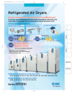
Refrigerated Air Dryers
Series IDF/IDU
Standard/High Temperature Air Inlet Type
Protect Pneumatic Equipment from Moisture!
HAA
HAW
An air dryer removes the vapor from the moist compressed air delivered by the
compressor, and prevents it from causing the pneumatic equipment to fail.
AT
IDF
IDU
Effects of moisture on equipment
Malfunctioning of valves and
actuators caused by dripping grease
Decomposition of auto drain
caused by rusting inside pipes
IDFA
Generation of water droplets
IDFB
ID
IDG
AMG
Increased up to the
Air flow
capacity
Max.
Reduced up to the
%
(SMC comparison,
E type)
Power
consumption
Max.
AFF
AM
%
(SMC comparison,
E type)
Note)
AMD
AMH
R134a (HFC)
Refrigerant
R407C (HFC)
AME
AMF
Coefficient of destruction for ozone is zero.
Note) Except IDF370B
SF
Improved corrosion resistance with the use of
stainless steel, plate type heat exchanger
SFD
(IDF4E to 75E/IDU3E to 75E)
LLB
AD쏔
GD
Standard temperature air inlet [Series IDF ]
IDF1E, 2E, 3E, 4E, 6E, 8E, 11E, 15E, 22E, 37E, 55E, 75E, 120D, 150D, 190D, 240D, 370B
High temperature air inlet [Series IDU ]
IDU3E, 4E, 6E, 8E, 11E, 15E, 22E, 37E, 55E, 75E
21
P0011-P0088-E.qxd
08.11.6 1:42 PM
Page 22
INDEX
Complies with CFC restrictions
Refrigerated Air Dryers
1. Standard Products
Series IDF
Model
Standard temperature air inlet type
Rated inlet air temperature:
IDF1E
35, 40°C
Rated
Air flow capacity (m3/min (ANR)) Applicable air
inlet
compressor (kW)
50 Hz
60 Hz
condition
0.1
0.12
0.75
IDF2E
0.2
0.235
1.5
IDF3E
0.32
0.37
2.2
IDF4E
0.52
0.57
3.7
IDF6E
0.75
0.82
5.5
Rc 1/2
1.22
1.32
1.65
1.82
11
IDF15E
2.8
3.1
15
Rc 1
IDF22E
3.9
4.3
22
R1
IDF37E
5.7
6.1
37
R1 1/2
IDF55E
8.4
9.8
55
IDF75E
11.0
12.4
75
IDF120D
40°C,
IDF150D 0.7 MPa
20.0
23.0
120
25.0
30.0
150
IDF190D
32.0
38.0
190
IDF240D
43.0
50.0
240
54.0
65.0
370
35°C,
Model
7.5
Rc 3/4
Rated
Air flow capacity (m3/min (ANR)) Applicable air
inlet
compressor (kW)
50 Hz
60 Hz
condition
65 (2 1/2B) flange
80 (3B) flange
P.33 to 35
100 (4B) flange
R22
150 (6B) flange
Refrigerant
Port size
0.32
0.37
2.2
Rc 3/8
IDU4E
0.52
0.57
3.7
Rc 1/2
IDU6E
0.75
0.82
5.5
IDU8E
1.1
1.2
7.5
1.5
1.7
11
2.6
2.8
15
IDU22E
3.9
4.3
22
R1
IDU37E
5.7
6.1
37
R 1 1/2
IDU55E
8.4
9.8
55
IDU75E
11.0
12.5
75
IDU15E
P.30 to 32
R2
IDU3E
IDU11E
P.26 to 29
R407C (HFC)
IDF370B 0.7 MPa
High temperature air inlet type
Rated inlet air temperature:
55°C
Page
Rc 3/8
R134a (HFC)
35°C,
0.7 MPa
Port size
IDF11E
IDF8E
Series IDU
Refrigerant
55°C,
0.7 MPa
R134a (HFC)
Rc 3/4
Page
P.36 to 38
Rc 1
R407C (HFC)
P.39 to 41
R2
∗ Refer to pages 59 and 73 for dryer models conforming with foreign standards (CE and UL).
22
P0011-P0088-E.qxd
08.11.6 1:42 PM
Page 23
INDEX
2. Options
Applicable model
Specifications
Cool compressed air output
IDF1E to 75E
IDF쏔E-쏔-A
IDF1E to 75E
IDF쏔E-쏔-C
Page
HAA
HAW
IDF120D to 240D IDF쏔D-쏔(-쏔)-C
Anti-corrosive treatment
For medium air pressure (up to 1.6 MPa)
(Auto drain bowl: Metal bowl with level gauge)
With heavy duty auto drain (applicable to medium air pressure)
With motor type auto drain
Model
(Suffix: Option symbol)
IDF370B
IDF370B-60쏔-X204
IDU3E to 75E
IDU쏔E-쏔-C
IDF6E to 37E
IDF쏔E-쏔-K
IDU3E to 15E
IDU쏔E-쏔-K
IDF4E to 75E
IDF쏔E-쏔-L
IDF370B
IDF370B-60쏔-X205
IDU3E to 75E
IDU쏔E-쏔-L
IDF4E to 75E
IDF쏔E-쏔-M
IDF120D to 240D IDF쏔D-쏔(-쏔)-M
Note 1)
IDU3E to 75E
IDU쏔E-쏔-M
IDF4E to 75E
IDF쏔E-쏔-R
IDF120D to 240D IDF쏔D-쏔(-쏔)-R
With circuit breaker
IDF370B
IDF370B-60쏔-X202
IDU3E to 75E
IDU쏔E-쏔-R
IDF4E to 15E-10
IDF쏔E-10-S
IDU3E to 15E-10
IDU쏔E-10-S
With terminal block for power supply, run, alarm signal and remote
operation
IDF4E to 75E
IDF쏔E-쏔-T
IDU3E to 75E
IDU쏔E-쏔-T
Timer type solenoid valve with auto drain (applicable to medium air pressure)
IDU3E to 75E
IDU쏔E-쏔-V
Water-cooled condenser Note 1)
IDF120D to 240D IDF쏔D-쏔(-쏔)-W
Power supply terminal block connection
AT
P.42
IDF
IDU
IDFA
IDFB
ID
P.43
IDG
AMG
P.44
AFF
AM
AMD
P.45
AMH
AME
P.46
AMF
Note 1) The IDF370B is equipped as standard.
SF
3. Optional Accessories
Description
Page
SFD
Separately installed power transformer
LLB
Dedicated base for separately installed power transformer
Dust-protecting filter set
Bypass piping set
P.47 to 54
AD쏔
Foundations bolt set
GD
Piping adapter
23
P0011-P0088-E.qxd
08.11.6 1:42 PM
Page 24
Series IDF/IDU
Model Selection
The corrected air flow capacity, which considers the user’s operating conditions, is required for selecting
the air dryer. Please select using the following procedures.
1
Selecting IDF or IDU
2
Reading correction
factors
Obtain the correction factor A to
D suitable for your operating
condition from the graph at right.
3
Confirmation of
coefficient
4
Calculating corrected
air flow capacity
Obtain the corrected air flow
capacity from the following formula.
Corrected air flow capacity =
Operating air flow capacity 앦
(Correction factor A x B x C x D)
5
Select IDF or IDU from inlet air temperature used.
• Inlet air temperature 5 to 50°C ····· IDF
• Inlet air temperature 50 to 80°C ····· IDU
IDF Selection Example
Condition
IDU Selection Example
Data
symbol
Correction Note)
factor
Condition
Correction Note)
factor
Inlet air temperature
40°C
A
0.82
Inlet air temperature
60°C
A
0.95
Ambient temperature
35°C
B
0.96
Ambient temperature
35°C
B
0.93
Outlet air pressure dew point
10°C
C
1
Outlet air pressure dew point
10°C
C
1
Inlet air pressure
0.5 MPa
D
0.88
Inlet air pressure
0.5 MPa
D
0.88
Air flow rate
0.3 m3/min
—
—
Air flow rate
0.4 m3/min
—
—
Power supply frequency
50 Hz
—
—
Power supply frequency
60 Hz
—
—
Note) Values obtained from “Correction Factors” on page 25.
Note) Values obtained from “Correction Factors” on page 25.
Correction factor = 0.82 x 0.96 x 1 x 0.88 = 0.69
Max. coefficient value is 1.5. Correction factor is 1.5
when the calculation result is 1.5 or greater.
Correction factor = 0.95 x 0.93 x 1 x 0.88 = 0.78
Max. coefficient value is 1.5. Correction factor is 1.5
when the calculation result is 1.5 or greater.
Corrected air flow capacity = 0.3 m3/min 앦 (0.82 x
0.96 x 1 x 0.88) = 0.43 m3/min
Corrected air flow capacity = 0.4 m3/min 앦 (0.95 x
0.93 x 1 x 0.88) = 0.51 m3/min
According to the corrected air flow capacity of 0.43
m3/min, the IDF4E will be selected which air flow
capacity is 0.52 m3/min at 50 Hz.
According to the corrected air flow capacity of 0.51
m3/min, the IDU4E will be selected which air flow
capacity is 0.57 m3/min at 60 Hz.
Selecting a model
Select a model which corrected air
flow capacity exceeds the air flow
capacity from the specification
table. (For air flow capacity, refer
to the data E on page 25.)
6
Options
Refer to pages 42 through to 46.
Refer to pages 42 through to 46.
7
Model selected
Refer to pages 26, 30 and 33.
Refer to pages 36 and 39.
8
Selecting optional
accessories
Refer to pages 47 through to 54.
24
Data
symbol
P0011-P0088-E.qxd
08.11.6 1:42 PM
Page 25
Model Selection
Correction Factors
Data A: Inlet Air Temperature
Series IDF
Series IDU
IDF1E to 37E
Inlet air temp. (°C)
Correction
factor
5 to 30
35
40
45
50
IDU3E to IDU37E
IDF55E, 75E, 120D to 240D IDF370B
IDU55E, 75E
Inlet air temp. (°C)
Correction
factor
Inlet air temp. (°C)
Correction
factor
Inlet air temp. (°C)
Correction
factor
Inlet air temp. (°C)
Correction
factor
5 to 30
35
40
45
50
1.35
5 to 30
35
40
45
50
1.25
5 to 45
50
55
60
65
70
75
80
1.15
5 to 45
50
55
60
65
70
75
80
1.21
1.3
1
0.82
0.68
0.57
1.25
1
0.8
0.6
1.00
0.83
0.70
0.60
1.07
1
0.95
0.9
0.86
0.82
0.79
1.10
1
0.87
0.76
0.74
0.72
0.70
Data B: Ambient Temperature
Series IDU
IDF120D to 240D
Ambient temp. (°C)
Correction
factor
2 to 25
30
32
35
40
1.14
Ambient temp. (°C)
Ambient temp. (°C)
2 to 25
30
32
35
40
1.10
2 to 25
30
32
35
40
1
0.96
0.9
1.05
1
0.95
0.90
Data D: Inlet Air Pressure
Series IDF
Series IDF
Series IDU
IDF1E to 75E,
IDU3E to IDU37E
120D to 240D, 370B
3
5
10
15
Outlet air pressure Correction
factor
dew point (°C)
3
5
10
15
0.55
0.7
1
1.3
0.55
0.7
1
1.3
IDU55E, 75E
Outlet air pressure Correction
dew point (°C)
factor
3
5
10
15
Correction
factor
Ambient temp. (°C)
Correction
factor
2 to 25
30
32
35
40
1.25
1.2
1.04
1
0.93
0.84
1.11
1
0.90
0.63
IDF1E to 75E
Inlet air
Correction
pressure
factor
(MPa)
0.2
0.3
0.4
0.5
0.6
0.7
0.8
0.9
1 to 1.6
Series IDU
IDF120D to 370B
Inlet air
Correction
pressure
factor
(MPa)
0.2
0.3
0.4
0.5
0.6
0.7
0.8
0.9
1.0
0.62
0.72
0.81
0.88
0.95
1
1.06
1.11
1.16
0.68
0.77
0.84
0.90
0.95
1
1.03
1.06
1.08
IDU3E to 37E IDU55E, 75E
AMG
AFF
AMH
Inlet air
Correction
pressure
factor
(MPa)
Inlet air
Correction
pressure
factor
(MPa)
AME
0.2
0.3
0.4
0.5
0.6
0.7
0.8
0.9
1 to 1.6
0.2
0.3
0.4
0.5
0.6
0.7
0.8
0.9
1 to 1.6
AMF
0.62
0.72
0.81
0.88
0.95
1
1.06
1.11
1.16
0.62
0.69
0.77
0.85
0.93
1
1.08
1.16
1.23
0.53
0.67
SF
SFD
LLB
AD쏔
GD
1
1.30
Series IDF
Model
IDF1E
IDF2E
IDF3E
IDF4E
IDF6E
IDF8E
Air flow capacity 50 Hz
m3/min (ANR) 60 Hz
0.10
0.20
0.32
0.52
0.75
1.22
1.65
2.8
3.9
5.7
8.4
11.0
0.12
0.235
0.37
0.57
0.82
1.32
1.82
3.1
4.3
6.1
9.8
12.4
Model
IDG
AMD
Data E: Air Flow Capacity
Air flow capacity 50 Hz
m3/min (ANR) 60 Hz
IDFA
AM
Data C: Outlet Air Pressure
Dew Point
Outlet air pressure Correction
dew point (°C)
factor
IDF
IDU
ID
IDU55E, 75E
IDU3E to IDU37E
Correction
factor
1.04
AT
IDFB
Series IDF
IDF1E to 75E
HAA
HAW
IDF11E IDF15E IDF22E IDF37E IDF55E IDF75E
IDF120D IDF150D IDF190D IDF240D IDF370B
20.0
25.0
32.0
43.0
54.0
23.0
30.0
38.0
50.0
65.0
Note) In the case of option A (Cool compressed air output), the air flow capacity is different. Refer to page 42 for details.
Series IDU
Model
IDU3E
IDU4E
IDU6E
IDU8E
Air flow capacity 50 Hz
m3/min (ANR) 60 Hz
0.32
0.52
0.75
1.1
IDU11E IDU15E IDU22E IDU37E IDU55E IDU75E
1.5
2.6
3.9
5.7
8.4
11.0
0.37
0.57
0.82
1.2
1.7
2.8
4.3
6.1
9.8
12.5
25
P0011-P0088-E.qxd
08.11.6 1:42 PM
Page 26
Refrigerant R134a (HFC)
Standard Temperature Air Inlet
Series IDF 쏔E
1E, 2E, 3E, 4E, 6E, 8E, 11E, 15E
(Inlet air temperature: 35°C, Outlet air pressure dew point: 10°C)
How to Order
IDF 8 E
10
Nil
A
C
K
L
M
R
S
T
Size
Size
Air compressor size Note)
1
2
3
4
6
8
11
15
0.75 kW
1.5 kW
2.2 kW
3.7 kW
5.5 kW
7.5 kW
11 kW
15 kW
Note) Please note that the above values
are for reference only. Therefore,
check the actual compressor
capacity.
Voltage
Symbol
Applicable size
Voltage
1
2
3
4
6
8
11
15
10
Single-phase
100 VAC (50 Hz)
100/110 VAC (60 Hz)
쎲
쎲
쎲
쎲
쎲
쎲
쎲
쎲
20
Single-phase
200 VAC (50 Hz)
200/220 VAC (60 Hz)
—
—
쎲
쎲
쎲
쎲
쎲
쎲
Option
Symbol Note 1)
Option
Size
1
2
3
4
6
8
11
15
Nil
A
C
Cool
AntiNone compressed corrosive
air output
treatment
쎲
쎲
쎲
쎲
쎲
쎲
쎲
쎲
쎲
쎲
쎲
쎲
쎲
쎲
쎲
쎲
쎲
쎲
쎲
쎲
쎲
쎲
쎲
쎲
K
L
M
R
For medium air
pressure Note 4)
Auto drain bowl:
Metal bowl with level gauge
With heavy
duty auto drain
(applicable to medium
air pressure) Note 4)
With motor
type
auto drain
With
circuit
breaker
—
—
—
—
—
—
—
—
—
—
—
—
—
쎲
쎲
쎲
쎲
쎲
쎲
쎲
쎲
쎲
쎲
쎲
쎲
쎲
쎲
쎲
쎲
쎲
쎲
쎲
Note 1) Enter alphabetically when multiple options are combined.
However, the following combinations are not possible.
• R and S (Because S function is also included in R.)
• S and T (Because S function is also included in T.)
• Combination of K, L and M are not possible because an auto drain can only be attached to a single option.
Note 2) Voltage symbol 20 (200 VAC) is the terminal block connection as standard. The option S cannot be chosen.
Voltage symbol 10 (100 VAC) is the power cable with plug as standard.
Note 3) Refer to pages 42 through to 45 for further information on options.
26
S
T
Terminal block With terminal
block for run
connection
(Voltage symbol and alarm
signal
10 only) Note 2)
쎲
쎲
쎲
쎲
쎲
쎲
쎲
쎲
—
—
—
쎲
쎲
쎲
쎲
쎲
P0011-P0088-E.qxd
08.11.6 1:42 PM
Page 27
Series IDF 쏔E
Refrigerated Air Dryer
Standard Specifications
Standard temperature air inlet
Model
IDF1E
Rated conditions Note 3)
Operating ranges
Specifications
JIS Symbol
Electric specifications
Refrigerated
air dryer
Auto drain
IDF2E
IDF3E
IDF4E
IDF6E
IDF8E IDF11E IDF15E
Compressed air
Fluid
5 to 50
Inlet air temperature (°C)
Inlet air pressure
0.15 to 1.0
(MPa)
2 to 40 (Relative humidity of 85% or less)
Ambient temp. (humidity) (°C)
Air flow
capacity
(m3/min)
Standard Note 1)
condition
(ANR)
50 Hz
0.10
0.20
0.32
0.52
0.75
1.22
1.65
2.8
60 Hz
0.12
0.235
0.37
0.57
0.82
1.32
1.82
3.1
Note 2)
Compressor intake
condition
50 Hz
0.10
0.21
0.33
0.54
0.78
1.27
1.72
2.9
60 Hz
(MPa)
0.12
0.24
0.38
0.59
0.85
1.37
1.9
3.2
Inlet air pressure
0.7
Inlet air temperature (°C)
35
Ambient temperature (°C)
32
Single-phase: 100 VAC (50 Hz), 100/110 VAC (60 Hz)
Single-phase: 200 VAC (50 Hz), 200/220 VAC (60 Hz)
Power supply voltage
(frequency) Note 4)
Power
consumption
(W) 50/60 Hz
Operating
current (A)
50/60 Hz
Single-phase 100 V 180/202
180/202
180/202
180/202
208/236
385/440
540/620
6.1/6.3
—
—
2.4/2.5
2.4/2.5
2.4/2.5
2.4/2.5
2.4/2.5
3.0/3.1
5.7/5.7
Single-phase 200 V
—
—
1.2/1.3
1.2/1.3
1.2/1.3
1.5/1.5
3.4/3.0
Air-cooled
Refrigerant
R134a (HFC)
(Normally closed)
Mass
(kg)
16
17
18
23
22
Applicable air compressor output (Reference)
For screw type
(kW)
0.75
1.5
2.2
27
28
AMH
46
AME
5.5
3.7
AFF
Rc 1
Body panel: White 1
Base: Gray 2
Coating color
AMG
AMD
Rc 3/4
Rc 1/2
Rc 3/8
IDG
AM
Float type
(Normally open)
Float type
Port size
3.8/4.0
10 (100 VAC)
10 (200 VAC)
10 (100 VAC), 5 (200 VAC)
Condenser
Auto drain
ID
180/202
Single-phase 100 V
(A)
IDF
IDU
IDFB
Note 4)
Single-phase 200 V
Applicable circuit
breaker capacity Note 5)
AT
IDFA
10
Outlet air pressure dew point (°C)
HAA
HAW
7.5
11
15
AMF
Note 1) Air flow capacity under the standard condition (ANR) [atmospheric pressure at 20°C, relative humidity at 65%]
Note 2) Air flow capacity converted by the compressor intake condition [atmospheric pressure at 32°C]
Note 3) Select air dryer according to “Model Selection” (pages 24 and 25) for the models beyond the rated specifications.
Note 4) When selecting a power supply voltage, refer to “How to Order” on page 26.
Note 5) Install a circuit breaker with a sensitivity of 30 mA.
SF
SFD
Replacement Parts
Model
Auto drain replacement parts no. Note 6)
IDF1E
IDF2E
AD37
IDF3E
IDF4E
IDF6E
IDF8E
AD38
IDF11E
IDF15E
AD48
Note 6) The part number for the auto drain components without including the body part.
Body part replacement is impossible.
Body
LLB
AD쏔
Auto drain
GD
Construction Principle (Air/Refrigerant Circuit)
Humid, hot air coming into the air dryer will be cooled down by a cooler (heat exchanger). Water condensed at this time will be removed from the air by a drain separator (auto drain) and drained out automatically. Air separated from the water will be heated by a re-heater (heat exchanger) to obtain the dried air, which goes through
to the outlet side.
IDF1E
IDF2E, IDF3E
Drain separator
Compressed air inlet
Compressed
Compressed air inlet
air outlet
Cooler
Re-heater
Drain outlet
Cooler
Drain separator
Compressed
air outlet
Re-heater
Drain outlet
Volume
control valve
Condenser
Volume
control valve
IDF4E, IDF6E
IDF8E, IDF11E, IDF15E
Compressed
air inlet
Compressed
air outlet
Evaporation
thermometer
Heat exchanger
Drain separator
Volume control
valve
Drain outlet
Capillary tube
Condenser
Pressure
switch
Capillary tube
Compressor for
refrigeration
Fan motor
Pressure switch
Capillary tube
Compressor for
refrigeration
Evaporation thermometer
Compressor for
refrigeration
Condenser
Pressure switch
Fan motor
Evaporation thermometer
Fan motor
27
P0011-P0088-E.qxd
08.11.6 1:42 PM
Page 28
Series IDF 쏔E
Dimensions
IDF1E to IDF3E
B
A
E
Ventilation
direction
D
Q
Air inlet
Illuminated switch
G
Port size
Evaporation
thermometer
C
Air outlet
Port size
Ventilation
air inlet
F
Ventilation
direction
IDF3E-20 only
L
J
Drain tube
(O.D. ø10, length
approx. 0.8 m)
K
P
N
H
[200 VAC specification]
M
[200 VAC
specification]
Terminal block
Power cable outlet (ø17)
[100 VAC specification]
Power cable (Length:
approx.1.9 m)
IDF4E to IDF11E
B
A
E
Q
D
Illuminated switch
Evaporation
thermometer
Air inlet
Port size
C
Ventilation
direction
Air outlet
Port size
F
Ventilation
direction
G
Ventilation
air outlet
Drain tube
(O.D. ø10, length
approx. 0.8 m)
N
4 x ø13
M
J
K
L
P
[200 VAC
specification]
[200 VAC specification]
[100 VAC specification]
Power cable outlet (ø17)
Power cable (Length:
approx.1.9 m)
Dimensions
Model
IDF1E
IDF2E
IDF3E
IDF4E
IDF6E
IDF8E
IDF11E
28
H
(mm)
Port size
Rc 3/8
A
226
B
410
C
413
473
Rc 1/2
Rc 3/4
453
270
455
485
D
E
F
G
69
101
270
32
232
138
304
33
51
67
125
J
K
L
—
—
38
150
73
31
36
154
M
N
21
330
24
327
21
330
283
498
31
568
H
42
Q
240
15
13
275
80
355
P
230
32
15
240
284
80
300
15
Terminal block
P0011-P0088-E.qxd
08.11.6 1:42 PM
Page 29
Refrigerated Air Dryer
Series IDF 쏔E
Dimensions
IDF15E
603
300
54 41
16
Ventilation air outlet
Air outlet
Rc 1
Illuminated switch
AT
Ventilation
air outlet
578
[200 VAC
specification]
Terminal block
396
Ventilation
direction
Ventilation
direction
HAA
HAW
Air inlet
Rc 1
87
Evaporation
thermometer
Drain tube
(O.D. ø10, length
approx. 0.8 m)
314
IDFA
IDFB
43
270
IDF
IDU
15
380
4 x ø13
101
ID
258
[100 VAC specification]
[200 VAC specification]
Power cable (Length: approx.1.9 m)
Power cable outlet (ø17)
IDG
AMG
AFF
AM
AMD
AMH
AME
AMF
SF
SFD
LLB
AD쏔
GD
29
P0011-P0088-E.qxd
08.11.6 1:42 PM
Page 30
Refrigerant R407C (HFC)
Standard Temperature Air Inlet
Series IDF 쏔E
22E, 37E, 55E, 75E
(Inlet air temp.: 35°C (22E, 37E), 40°C (55E, 75E), Outlet air pressure dew point: 10°C)
How to Order
IDF 55 E
30
Size
Size
Air compressor size Note)
22
37
55
75
22 kW
37 kW
55 kW
Nil
A
C
K
L
M
R
T
75 kW
Note) Please note that the above values
are for reference only. Therefore,
check the actual compressor
capacity.
Voltage
Symbol
Voltage
Applicable size
22
37
55
75
20
Single-phase
200 VAC (50 Hz)
200/220 VAC (60 Hz)
쎲
쎲
—
—
30
Three-phase
200 VAC (50 Hz)
200/220 VAC (60 Hz)
쎲
쎲
쎲
쎲
Option
Symbol Note 1)
Option
Size
22
37
55
75
Nil
A
C
Cool
AntiNone compressed corrosive
air output treatment
쎲
쎲
쎲
쎲
쎲
쎲
쎲
쎲
쎲
쎲
쎲
쎲
K
For medium air pressure
Auto drain bowl:
Metal bowl with level gauge
쎲
쎲
— Note 2)
— Note 2)
L
With heavy
With motor
duty auto drain
type
(applicable to
medium air pressure) auto drain
쎲
쎲
쎲
쎲
Note 1) Enter alphabetically when multiple options are combined.
However, the following combinations are not possible.
• Combination of K, L and M are not possible because an auto drain can only be attached to a single option.
Note 2) Select the option L for the 55E and 75E which need medium air pressure.
Note 3) Refer to pages 42 through to 45 for further information on options.
30
M
쎲
쎲
쎲
쎲
R
T
With
circuit
breaker
With terminal
block for run
and alarm
signal
쎲
쎲
쎲
쎲
쎲
쎲
쎲
쎲
P0011-P0088-E.qxd
08.11.6 1:42 PM
Page 31
Refrigerated Air Dryer
Series IDF 쏔E
Standard Specifications
Standard temperature air inlet
Model
IDF22E
Electric specifications
Rated conditions Note 3)
Operating ranges
Specifications
IDF37E
Inlet air temperature
Inlet air pressure
Standard
condition
(ANR)
Note 1)
0.15 to 1.0
Note 2)
Compressor intake
condition
Inlet air pressure
2 to 40 (Relative humidity of 85% or less)
(°C)
50 Hz
3.9
5.7
8.4
11.0
60 Hz
4.3
6.1
9.8
12.4
50 Hz
4.1
5.9
8.7
11.5
60 Hz
4.5
6.4
10.2
12.9
Inlet air temperature
(°C)
Ambient temperature
(°C)
35
Power
consumption
(W) 50/60 Hz
Operating
current (A)
50/60 Hz
AT
IDF
IDU
40
IDFA
32
10
Outlet air pressure dew point (°C)
Single-phase/Three-phase: 200 VAC (50 Hz) Note 4)
Single-phase/Three-phase: 200/220 VAC (60 Hz)
Power supply voltage
(frequency) Note 4)
HAA
HAW
0.7
(MPa)
Three-phase: 200 VAC (50 Hz)
Three-phase: 200/220 VAC (60 Hz)
Single-phase 200 V
810/940
810/940
—
—
Three-phase 200 V
850/1070
850/1070
1300/1700
2000/2500
Single-phase 200 V
4.3/4.7
4.3/4.7
—
—
Three-phase 200 V
3.3/3.5
3.3/3.5
5.0/5.4
7.2/8.0
Applicable circuit breaker
capacity Note 5)
(A)
10 (200 VAC)
15 (200 VAC)
Air-cooled
Refrigerant
R407C (HFC)
R 1 1/2
R1
(kg)
Mass
62
54
Coating color
Applicable air compressor output (Reference)
For screw type
(kW)
22
37
100
55
AMH
75
AME
Replacement Parts
Model
Auto drain replacement parts no. Note 6)
ID22E
IDF37E
IDF55E
AMG
AMD
116
Note 1) Air flow capacity under the standard condition (ANR) [atmospheric pressure at 20°C, relative humidity
at 65%]
Note 2) Air flow capacity converted by the compressor intake condition [atmospheric pressure at 32°C]
Note 3) Select air dryer according to “Model Selection” (pages 24 and 25) for the models beyond the rated
specifications.
Note 4) When selecting a power supply voltage, refer to “How to Order” on page 30.
Note 5) Install a circuit breaker with a sensitivity of 30 mA.
Auto drain
IDG
R2
Body panel: White 1
Base: Gray 2
JIS Symbol
ID
AM
Float type (Normally open)
Port size
IDFB
AFF
Condenser
Auto drain
Refrigerated
air dryer
IDF75E
5 to 50
(°C)
(MPa)
Ambient temp. (humidity)
Air flow
capacity
(m3/min)
IDF55E
Compressed air
Fluid
IDF75E
AD48
Note 6) The part number for the auto drain components without including the body part.
Body part replacement is impossible.
AMF
SF
SFD
LLB
Body
Auto drain
AD쏔
GD
Construction Principle (Air/Refrigerant Circuit)
Humid, hot air coming into the air dryer will be cooled down by a cooler re-heater (heat exchanger). Water condensed at this time will be removed from the air by an
auto drain and drained out automatically. Air separated from the water will be heated by a cooler re-heater (heat exchanger) to obtain the dried air, which goes through
to the outlet side.
IDF22E, IDF37E, IDF55E, IDF75E
Compressed
air inlet
Compressed
air outlet
Evaporation thermometer
Cooler re-heater
(Heat exchanger)
Accumulator
(IDF22E, 37E, 55E only)
Compressor for
refrigeration
Auto drain
Ball valve
Volume
control valve
Drain outlet
Capillary tube
Condenser
Fan motor
High pressure switch
(IDF55E, 75E only)
Pressure switch
31
P0011-P0088-E.qxd
08.11.6 1:42 PM
Page 32
Series IDF 쏔E
Dimensions
IDF22E, IDF37E
Air inlet
Port size
Air outlet
Port size
A
B
E
G
D
Illuminated switch
Evaporation
thermometer
Ventilation
air outlet
Ball valve
F
Ventilation
direction
C
Ventilation
direction
Terminal
block
J
Drain tube
(O.D. ø10, length
approx. 0.8 m)
L
K
N
H
P
M
4 x ø13
Power cable holder
(Electric wire diameter
ø9 to 11) [opposite side]
Auto drain
IDF55E, IDF75E
R
A
G
Air inlet
Port size
Air outlet
Port size
B
Q
E
Illuminated switch
D
Ventilation air outlet
Evaporation
thermometer
Ball valve
Terminal
block
F
C
Auto drain
Ventilation
direction
J
Ventilation
direction
K
L
P
Drain tube
M
N
(O.D. ø10, length
approx. 1 m)
H
4 x ø13
Power cable holder
(Electric wire diameter
ø9 to 11) [opposite side]
Dimensions
(mm)
Model
Port size
IDF22E
IDF37E
IDF55E
IDF75E
R1
32
R 1 1/2
R2
A
290
470
B
775
855
855
C
623
800
900
D
E
134
405
128
455
F
698
868
968
G
H
J
K
L
M
93
46
25
13
314
85
110
36
50
13
500
75
N
600
680
700
P
Q
R
340
—
—
526
250
519
P0011-P0088-E.qxd
08.11.6 1:42 PM
Page 33
Refrigerant R407C (HFC) / R22
Standard Temperature Air Inlet
Series IDF 쏔D,
120D, 150D, 190D, 240D, 370B
B
(Inlet air temp.: 40°C (120D, 150D, 190D, 240D), 35°C (370B), Outlet air pressure dew point: 10°C)
HAA
HAW
How to Order
AT
Refrigerant R407C
IDF120D to IDF240D
IDF
IDU
IDF 120 D
3
9
Size
Size
Compressor size
120
150
190
240
120 kW
150 kW
190 kW
240 kW
Voltage
Symbol
220V
240V
380V
400V
415V
440V
Voltage
3
Three-phase
200 VAC (50 Hz)
200/220 VAC (60 Hz)
9
Three-phase different voltage
(Built-in transformer)
IDFA
Nil
C
M
R
W
IDFB
ID
IDG
Option
AMG
Option
Symbol
None
Nil
C
M
R
W Note)
AFF
Anti-corrosive treatment
With motor type auto drain
AM
With circuit breaker
Water-cooled condenser
AMD
Note 1) Combination of a voltage symbol “9” and
an option symbol “W” is not available.
(Order Transformer separately.)
Note 2) Enter alphabetically when multiple
options are combined.
Note 3) Refer to pages 42 through to 46 for
further information on options.
AMH
AME
AMF
Refrigerant R22
IDF370B
SF
IDF 370 B 60 3
9
Size
Size
Compressor size
370
370 kW
Port size
Symbol
Port size
60
150 (6B) flange
Voltage
Symbol
3
Voltage
Three-phase
200 VAC (50/60 Hz)
220V
240V
380V
400V
415V
440V
Nil
SFD
X202
X204
X205
LLB
AD쏔
Option
Symbol
Nil
X202
X204
X205
GD
Option
None
With circuit breaker
Anti-corrosive treatment
With heavy duty auto drain Note 3)
Note 1) When more than one operation is
required, indicate in numeric order.
Note 2) Refer to pages 42 and 44 for further
information on options.
Note 3) Not applicable to the medium air
pressure.
9 Note) Three-phase different voltage
Note) Transformer integrated into the base
33
P0011-P0088-E.qxd
08.11.6 1:42 PM
Series IDF 쏔D,
Page 34
B
Standard Specifications
Water-Cooled Condenser
Specifications (IDF370B)
Electric specifications Rated conditions Note 3) Operating ranges
Standard temperature air inlet
Model
Specifications
IDF120D IDF150D IDF190D IDF240D IDF370B
Compressed air
Fluid
5 to 50
Inlet air temperature (°C)
0.15 to 0.97
Inlet air pressure (MPa)
2 to 43 (Relative humidity of 85% or less)
Ambient temp. (humidity) (°C)
Standard Note 1) 50 Hz
20
25
32
43
54
Air flow condition
23
30
38
50
65
60 Hz
(ANR)
capacity ComNote 2) 50 Hz
21
26
33
45
56
(m3/min) pressor intake
24
31
40
52
68
60 Hz
condition
0.7
Inlet air pressure (MPa)
40
35
Inlet air temperature (°C)
32
—
Ambient temperature (°C)
10
Outlet air pressure dew point (°C)
Three-phase: 200 VAC
Power supply voltage
Three-phase: 200 VAC (50 Hz), 200/220 VAC (60 Hz)
(frequency) Note 4)
(50/60 Hz)
Power
2.5
4.0
4.9
6.3
8.1
Three-phase
consumption
3.1
5.0
5.9
7.6
9.5
(kW) 50/60 Hz 200 V
Operating
9.8
15.3
19.5
26.1
28.0
Three-phase
current (A)
200 V
10.1
16.1
20.1
26.4
31.0
50/60 Hz
Applicable circuit breaker
30
45
50
60
80
Note 5)
(A)
capacity
Condenser
Air-cooled
Water-cooled
Refrigerant
R407C (HFC)
R22
Auto drain
ADH4000-04
ADM200-042-8
Port size Note 6)
65 (2 1/2B) flange
80 (3B) flange
100 (4B) fange 150 (6B) flange
(kg)
Mass
1100
330
350
450
660
Coating color
Applicable air compressor output (Reference)
For screw type
(kW)
120
150
190
240
Shell and tube type
100 l/min
Cooling tower Note 2)
performance
10 RT
Water flow regulator
Pressure type automatic
water supply valve
Fluid port size
1 1/4 union
Note 1) Value when cooling water inlet temperature is
32°C and with rated load
Note 2) Calculated at 1 RT = 3,300 kcal/h
Motor Type Auto Drain
Model
Operating cycle
IDF370B
4 times per minute
For 8 sec/min
Power supply
200 VAC 50/60 Hz
Power
consumption
4W
JIS Symbol
Operating panel
part: Sky blue
Other panel
(except base):
White
Body panel: White
Base: Black
Condenser
Cooling water flow Note 1)
Refrigerated
air dryer
370
Note 1) Air flow capacity under the standard condition (ANR) [atmospheric pressure at 20°C, relative humidity at 65%]
Note 2) Air flow capacity converted by the compressor intake condition [atmospheric pressure at 32°C]
Note 3) Select air dryer according to “Model Selection” (pages 24 and 25) for the models beyond the rated specifications.
Note 4) When selecting a power supply voltage, refer to “How to Order” on page 33.
Note 5) Install a circuit breaker with a sensitivity of 30 mA.
Note 6) JIS 10K FF is used as a flange.
Auto drain
Construction Principle (Air/Refrigerant Circuit)
IDF120D to IDF240D
q Air re-heater
w Air cooler
Compressed air inlet
Air pressure
gauge
e Auto drain
Compressed
air outlet
Drain
Evaporation
thermometer
Capillary tube
Low pressure switch
Compressor for refrigeration
Volume control valve
Pressure switch
High pressure switch
Condenser
Fan motor
IDF370B
Compressed air inlet Compressed air outlet
Compressor for refrigeration
Accumulator
Volume control valve
Temperature
expansion valve
Automatic water
supply valve
q Air re-heater
w Air cooler
Drain
34
Water-cooled condenser
e Motor type auto drain
High temperature humid air from the air compressor
passes through the air re-heater q and is pre-cooled
by dehumified cool air. Then it is cooled to the specified temperature by the air cooler w using the evaporation heat of refrigerant.
At this time, the oil mist and moisture generated by
condensation are automatically exhausted by the auto
drain e. The cooled and dehumidified air goes back
to the air re-heater q and heat is exchanged with hot
air that flows into the air re-heater. It is supplied as dry
warm air without “sweating” in the piping system.
P0011-P0088-E.qxd
08.11.6 1:42 PM
Page 35
Refrigerated Air Dryer
Series IDF 쏔D,
B
Dimensions
IDF120D, IDF150D, IDF190D, IDF240D
A
(80)
Port size
(JIS 10K FF)
100
B
D
Ventilation air inlet
Ventilation
direction
Air inlet
HAA
HAW
F
Ventilation
direction
Ventilation
direction
C
AT
Power connection
Air outlet
Grommet with membrane
(Bottom hole ø36)
200
G
H
4 x ø20
IDF
IDU
E
J
Drain outlet
Rc 1/2
IDFA
IDFB
I
ID
(mm)
Model
Inlet and outlet port
IDF120D JIS 10K FF 65(2 1/2B) flange
IDF150D JIS 10K FF 80(3B) flange
IDF190D JIS 10K FF 80(3B) flange
IDF240D JIS 10K FF 100(4B) flange
A
B
C
D
E
F
G
H
I
J
650
1200
1300
325
470
600
600
660
330
365
750
1510
1320
375
480
600
700
800
355
427
770
1550
1640
385
703
730
700
800
355
592
IDG
AMG
∗ Auto drain is enclosed in the same shipping package as the main body. The customer is required to mount the auto drain to the air dryer.
AFF
IDF370B
AM
Air inlet
Air outlet
AMD
Port size
(280)
(400)
(JIS 10K FF 150(6B))
(310)
AMH
AME
Power cable outlet
AMF
1670
SF
75
Cooling water
inlet
(Rc 1 1/4)
650
SFD
(190)
(250)
100
Cooling water
outlet
(Rc 1 1/4)
(90)
LLB
AD쏔
(210)
(390)
1050
(800)
Drain outlet
Rc 3/8
4 x ø20
1810
GD
Power Transformer Integrated Type
IDF370B
The power transformer marked with the voltage symbol 9 is integrated into
the refrigerated air dryer.
Transformer box
Power connection
(ø36)
(560)
The power transformer marked with the voltage symbol 9 is built into the
inside of the main unit, and the outside dimensions are to the same as
those with the voltage symbol 3.
(1795)
IDF120D to 240D
(440)
1700 ±3
(2240)
4 x ø20
(Hole for foundation bolt)
35
P0011-P0088-E.qxd
08.11.6 1:42 PM
Page 36
Refrigerant R134a (HFC)
High Temperature Air Inlet
Series IDU 쏔E
3E, 4E, 6E, 8E, 11E, 15E
(Inlet air temperature: 55°C, Outlet air pressure dew point: 10°C)
How to Order
IDU 4 E
10
Nil
C
K
L
M
R
S
T
V
Size
Size
Air compressor size Note)
3
4
6
8
11
15
2.2 kW
3.7 kW
5.5 kW
7.5 kW
11 kW
15 kW
Note) Please note that the above values
are for reference only. Therefore,
check the actual compressor
capacity.
Voltage
Symbol
Applicable size
Voltage
3
4
6
8
11
15
10
Single-phase
100 VAC (50 Hz)
100/110 VAC (60 Hz)
쎲
쎲
쎲
쎲
쎲
쎲
20
Single-phase
200 VAC (50 Hz)
200/220 VAC (60 Hz)
쎲
쎲
쎲
쎲
쎲
쎲
23
Single-phase
230 VAC (50 Hz)
쎲
쎲
쎲
쎲
쎲
쎲
Option
Symbol Note 1)
Nil
C
Option
AntiNone corrosive
treatment
Size
3
4
6
8
11
15
쎲
쎲
쎲
쎲
쎲
쎲
쎲
쎲
쎲
쎲
쎲
쎲
K
L
M
With heavy
For medium air pressure duty auto drain With motor type
Auto drain bowl:
auto drain
(applicable to
Metal bowl with
(Voltage symbol
medium
level gauge
10, 20 only)
air pressure)
쎲
쎲
쎲
쎲
쎲
쎲
쎲
쎲
쎲
쎲
쎲
— Note 4)
쎲
쎲
쎲
쎲
쎲
쎲
R
S
With
circuit
breaker
Terminal block
connection
(Voltage symbol
10 only) Note 2)
쎲
쎲
쎲
쎲
쎲
쎲
쎲
쎲
쎲
쎲
쎲
쎲
Note 1) Enter alphabetically when multiple options are combined.
However, the following combinations are not possible.
• R and S (Because S function is also included in R.)
• S and T (Because S function is also included in T.)
• Combination of K, L, M and V are not possible because an auto drain can only be attached to a single option.
Note 2) Voltage symbol 20 (200 VAC) and 23 (230 VAC) are the terminal block connection as standard. The option S cannot be chosen.
Voltage symbol 10 (100 VAC) is the power cable with plug as standard.
Note 3) Refer to pages 42 through to 46 for further information on options.
Note 4) The mounting frame (special order) for the IDU15E is attached to the option L. For further details, please consult with SMC.
36
T
V
Timer type
solenoid valve
With terminal
with auto drain
block for run
(Voltage symbol 23 only)
and alarm
(applicable to
signal
medium air pressure)
쎲
쎲
쎲
쎲
쎲
쎲
쎲
쎲
쎲
쎲
쎲
쎲
P0011-P0088-E.qxd
08.11.6 1:42 PM
Page 37
Series IDU 쏔E
Refrigerated Air Dryer
Standard Specifications
Model
Electric specifications
Rated conditions Note 3)
Operating ranges
Specifications
IDU4E
IDU6E
Fluid
Inlet air temperature
Inlet air pressure
Standard
condition
(ANR)
Note 1)
Note 2)
Compressor intake
condition
Inlet air pressure
0.15 to 1.0
0.32
0.52
0.75
1.1
1.5
2.6
60 Hz
0.37
0.57
0.82
1.2
1.7
2.8
50 Hz
0.33
0.54
0.78
1.14
1.6
2.7
60 Hz
0.38
0.59
0.85
1.25
1.8
2.9
(MPa)
0.7
(°C)
55
Ambient temperature
(°C)
32
Outlet air pressure dew point (°C)
Power
consumption Single-phase 200 V
(W) 50/60 Hz Single-phase 230 V (50 Hz)
Operating
current
(A) 50/60 Hz
AT
IDF
IDU
IDFA
IDFB
10
Single-phase: 100 VAC (50 Hz), 100/110 VAC (60 Hz) Note 4)
Single-phase: 200 VAC (50 Hz), 200/220 VAC (60 Hz)
Single-phase: 230 VAC ±10% (50 Hz)
Power supply voltage
(frequency) Note 4)
Single-phase 100 V
HAA
HAW
2 to 40 (Relative humidity of 85% or less)
(°C)
Inlet air temperature
Note 5)
180/202
385/440
208/236
425/470
250/290
ID
Note 5)
Note 5)
585/685
210
220
400
260
425
550
100 V
2.4/2.5
3.0/3.1
5.7/5.7
3.4/3.5
5.7/6.0
6.2/6.3
200 V
1.2/1.3
1.5/1.5
3.4/3.0
1.7/1.7
3.5/3.2
4.1/4.0
1.5
1.6
2.9
1.7
3.0
230 V (50 Hz)
(A)
10 (100 VAC), 5 (200 VAC, 230 VAC)
Refrigerant
R134a (HFC)
Auto drain
Float type (Normally open)
(kg)
Mass
Rc 3/8
Rc 1/2
23
27
28
Applicable air compressor output (Reference)
For screw type
(kW)
3.7
AFF
AM
AMD
Rc 1
44
5.5
AMH
71
47
AME
7.5
AMF
15
11
Note 1) Air flow capacity under the standard condition (ANR) [atmospheric pressure at 20°C, relative humidity at 65%]
Note 2) Air flow capacity converted by the compressor intake condition [atmospheric pressure at 32°C]
Note 3) Select air dryer according to “Model Selection” (pages 24 and 25) for the models beyond the rated specifications.
Note 4) When selecting a power supply voltage, refer to “How to Order” on page 36.
Note 5) For the models IDU8E or larger, the energy saving function is performed by the addition of an aftercooler.
Note 6) Install a circuit breaker with a sensitivity of 30 mA.
SF
SFD
LLB
Replacement Parts
Model
Auto drain replacement parts no. Note 7)
IDU3E
IDU4E
IDU6E
IDU8E
IDU11E
AD48
IDU15E
AMG-CA450-D
AD쏔
Body
Note 7) The part number for the auto drain components without including the body part.
Body part replacement is impossible.
Auto drain
GD
Construction Principle (Air/Refrigerant Circuit)
Humid, hot air coming into the air dryer will be cooled down by a heat exchanger. Water condensed at this time will be removed from the air by a drain separator and
drained out automatically. Air separated from the water will be heated by a heat exchanger to obtain the dried air, which goes through to the outlet side.
For models IDU8E to 15E, the humid and hot air introduced to the air dryer will be cooled down by the aftercooler before being cooled down by the heat exchanger.
IDU3E, IDU4E, IDU6E
IDU8E, IDU11E, IDU15E
Aftercooler
Fan motor
Compressed air inlet
Evaporation
thermometer
Heat exchanger
Heat exchanger
Compressed air inlet
Compressed air outlet
Compressed air outlet
Drain outlet
Drain separator
Volume control valve
Compressor for refrigeration
Condenser
Fan motor
Evaporation
thermometer
Drain outlet
Drain separator
Volume control valve
Compressor for refrigeration
Capillary tube
Condenser
Pressure switch
Fan motor
AMG
3.4
Body panel: White 1
Base: Gray 2
2.2
IDG
10 (100 VAC)
10 (200 VAC)
Rc 3/4
Coating color
Auto drain
IDU15E
50 Hz
Port size
Refrigerated
air dryer
IDU11E
5 to 80
(°C)
(MPa)
Ambient temp. (humidity)
Air flow
capacity
(m3/min)
IDU8E
Compressed air
Applicable circuit
breaker capacity Note 6)
JIS Symbol
High temperature air inlet
IDU3E
Capillary tube
Pressure switch
37
P0011-P0088-E.qxd
08.11.6 1:42 PM
Page 38
Series IDU 쏔E
Dimensions
IDU3E to IDU6E
B
A
E
Q
D
Illuminated switch
Evaporation
thermometer
Air inlet
Port size
C
Ventilation
direction
Air outlet
Port size
F
Ventilation
direction
G
Ventilation
air outlet
Drain tube
(O.D. ø10, length
approx. 0.8 m)
N
4 x ø13
Dimensions
Model
Port size
IDU3E
IDU4E
IDU6E
Rc 3/8
Rc 1/2
A
270
Rc 3/4
B
C
455
498
483
485
568
D
E
F
M
J
K
L
P
[200 VAC
specification]
[100 VAC specification]
[200 VAC specification]
Power cable
(Length: approx. 1.9 m)
Power cable outlet (ø17)
G
H
J
(mm)
K
L
M
N
283
31
42
355
P
230
32
15
240
80
300
Q
15
275
80
Terminal block
H
284
13
15
IDU8E to IDU15E
A
E
B
D
Q
Illuminated switch
Ventilation
air outlet
Evaporation
thermometer
Ventilation
direction
Ventilation
direction
C
G
Air inlet
Port size
Ventilation
direction
Air outlet
Port size
[200 VAC
specification]
Ventilation
direction
42
F
Terminal block
L
14
N
4 x ø13
P
Drain tube
(O.D. ø10, length approx. 0.8 m)
H
M
[200 VAC specification]
[100 VAC specification]
Power cable
(Length: approx. 1.9 m)
Power cable outlet (ø17)
Dimensions
Model
IDU8E
IDU11E
IDU15E
38
(mm)
Port size
A
B
Rc 3/4
270
485
Rc 1
300
620
C
859
909
960
D
E
F
G
H
L
M
N
P
Q
31
90
365
130
230
300
80
300
328
15
79
54
425
93
258
330
66
470
358
16
P0011-P0088-E.qxd
08.11.6 1:42 PM
Page 39
Refrigerant R407C (HFC)
High Temperature Air Inlet
Series IDU 쏔E
22E, 37E, 55E, 75E
(Inlet air temperature: 55°C, Outlet air pressure dew point: 10°C)
HAA
HAW
How to Order
IDU 22 E
30
Size
Size
Air compressor size Note)
22
37
55
75
22 kW
37 kW
AT
Nil
IDF
IDU
C
L
M
R
T
V
IDFA
IDFB
ID
55 kW
75 kW
IDG
Note) Please note that the above values
are for reference only. Therefore,
check the actual compressor
capacity.
AMG
Voltage
Symbol
AFF
Voltage
23
Single-phase
230 VAC (50 Hz)
AM
30
Three-phase
200 VAC (50 Hz)
200/220 VAC (60 Hz)
AMD
AMH
AME
Option
Symbol
Note 1)
Nil
C
Option
None
Anticorrosive
treatment
쎲
쎲
쎲
쎲
쎲
쎲
쎲
쎲
Size
22
37
55
75
L
M
R
With heavy
duty auto drain
(applicable to
medium air
pressure)
With motor type
auto drain
(Voltage symbol
30 only)
With
circuit
breaker
쎲
쎲
쎲
쎲
쎲
쎲
쎲
쎲
쎲
쎲
쎲
쎲
T
V
AMF
Timer type solenoid
With terminal
valve with auto drain
block for run (Voltage symbol 23 only)
and alarm
(applicable to medium
signal
air pressure)
쎲
쎲
쎲
쎲
SF
SFD
쎲
쎲
쎲
쎲
LLB
AD쏔
Note 1) Enter alphabetically when multiple options are combined.
However, the following combinations are not possible.
• Combination of L, M and V are not possible because an auto drain can only be attached to a single option.
Note 2) Refer to pages 42 through to 45 for further information on options.
GD
39
P0011-P0088-E.qxd
08.11.6 1:42 PM
Page 40
Series IDU 쏔E
Standard Specifications
Model
Electric specifications
Rated conditions Note 3)
Operating ranges
Specifications
High temperature air inlet
IDU22E
IDU37E
Fluid
Inlet air temperature
Inlet air pressure
Air flow
capacity
(m3/min)
0.15 to 1.0
2 to 40 (Relative humidity of 85% or less)
(°C)
Standard Note 1)
condition
(ANR)
50 Hz
3.9
5.7
8.4
11.0
60 Hz
4.3
6.1
9.8
12.5
Note 2)
Compressor intake
condition
50 Hz
4.1
5.9
8.7
11.5
60 Hz
4.5
6.4
10.2
13.0
Inlet air pressure
(MPa)
0.7
Inlet air temperature
(°C)
55
Ambient temperature
(°C)
32
Outlet air pressure dew point (°C)
10
Power supply voltage
(frequency)
Three-phase: 200 VAC (50 Hz)
Three-phase: 200/220 VAC (60 Hz)
1100/1450
Three-phase 200 V
Single-phase 230 V (50 Hz)
960
4.3
6.3/6.8
8.2/9.3
2300
7.5
Three-phase 200 V
10
Single-phase 230 V (50 Hz)
10
10.7
15
20
R407C (HFC)
Auto drain
Float type (Normally open)
R 1 1/2
R1
Port size
Auto drain
2200/2850
4.2/4.8
Three-phase 200 V
Single-phase 230 V (50 Hz)
1530/2000
1600
Refrigerant
Refrigerated
air dryer
IDU75E
5 to 80
(°C)
(MPa)
Ambient temp. (humidity)
Power
consumption
(W) 50/60 Hz
Operating
current
(A) 50/60 Hz
Applicable
circuit breaker (A)
capacity Note 4)
JIS Symbol
IDU55E
Compressed air
(kg)
Mass
90
130
R2
160
166
Body panel: White 1
Base: Gray 2
Coating color
Applicable air compressor output (Reference)
For screw type
(kW)
22
37
55
75
Note 1) Air flow capacity under the standard condition (ANR) [atmospheric pressure at 20°C, relative humidity at 65%]
Note 2) Air flow capacity converted by the compressor intake condition [atmospheric pressure at 32°C]
Note 3) Select air dryer according to “Model Selection” (pages 24 and 25) for the models beyond the rated specifications.
Note 4) Install a circuit breaker with a sensitivity of 30 mA.
Replacement Parts
IDU22E
Model
IDU37E
Auto drain replacement parts no. Note 5)
IDU55E
IDU75E
AD48
Note 5) The part number for the auto drain components without including the body part.
Body part replacement is impossible.
Body
Auto drain
Construction Principle (Air/Refrigerant Circuit)
Humid, hot air coming into the air dryer will be cooled down by a heat exchanger. Water condensed at this time will be removed from the air by a drain separator and
drained out automatically. Air separated from the water will be heated by a heat exchanger to obtain the dried air, which goes through to the outlet side.
IDU22E, IDU37E, IDU55E, IDU75E
Compressed
air inlet
High pressure switch
(IDU55E, 75E only)
Evaporation thermometer
Volume
control valve
Compressed air outlet
Cooler re-heater (Heat exchanger)
Auto drain
Drain outlet
Capillary tube
Condenser
Fan motor
40
Fan motor
Valve
Accumulator
Compressor for refrigeration
Aftercooler
High pressure switch
(IDU55E, 75E only)
Pressure switch
P0011-P0088-E.qxd
08.11.6 1:42 PM
Page 41
Refrigerated Air Dryer
Series IDU 쏔E
Dimensions
IDU22E to 75E
Air outlet
Port size
A
G
Evaporation
thermometer
Air inlet
Port size
B
E
(F)
Illuminated switch
Ventilation
direction
HAA
HAW
AT
Ventilation
direction
IDF
IDU
IDFA
Ventilation air outlet
IDFB
C
(D)
Ball valve
ID
IDG
Drain tube
(O.D. ø10, length
approx. 1 m)
AMG
J
Terminal
block
AFF
L
13
N
Power cable holder
(Electric wire diameter
ø9 to 11) [opposite side]
P
AM
M
4 x ø13
H
AMD
AMH
Dimensions
Model
IDU22E
IDU37E
IDU55E
IDU75E
(mm)
Port size
A
B
C
D
E
F
G
775
1153
1235
445
93
279
1258
1350
550
64
290
1345
1440
1480
1575
530
53
360
R1
325
R 1 1/2
360
R2
470
855
H
46
30
J
L
353
50
70
388
500
M
85
75
AME
N
P
600
379
680
414
AMF
700
526
SF
SFD
LLB
AD쏔
GD
41
P0011-P0088-E.qxd
08.11.6 1:42 PM
Page 42
Series IDF/IDU
Options 1
Option symbol
IDF쏔E
all models
Cool compressed air output
Cool outlet air (10°C) can be supplied.
The air flow with this option is smaller than that of the standard dryer.
(Refer to the below table.)
If the dryer is used out of the scope of the rated specifications or conditions, select a model according to pages 24 and 25 and apply the air flow
capacity shown in the tables below to the data E.
Note 1) Perform thermal insulation treatment for pipings and equipment
installed after the dryer to prevent the formation of condensation.
Note 2) The option A cannot be used for the IDF120D to 370B and the
IDU series due to the construction of the heat exchanger unit.
Air Flow Capacity
IDF1E
Model
IDF2E
IDF3E
IDF4E
0.085
0.12
0.18
0.26
0.1
0.14
0.21
0.29
IDF6E
IDF8E
IDF11E
IDF15E
0.32
0.5
0.65
1.2
0.375
0.55
0.75
1.3
IDF22E
IDF37E
IDF55E
IDF75E
1.7
2.6
3.85
5.35
1.9
3.05
4.5
6.2
Air flow capacity 50 Hz
m3/min (ANR)
60 Hz
Model
Air flow capacity 50 Hz
m3/min (ANR)
60 Hz
Model
Air flow capacity 50 Hz
m3/min (ANR)
60 Hz
(Rated specification/Conditions): Inlet air pressure: 0.7 MPa, Inlet air temperature:
35°C (IDF1E to 37E), 40°C (IDF55E, 75E)
Outlet air temperature: 10°C
C
Option symbol
IDF, IDU
all models
Anti-corrosive treatment
This minimizes the corrosion of the copper and copper alloy parts when
the air dryer is used in an atmosphere containing hydrogen sulfide or sulfurous acid gas. (Corrosion cannot be completely prevented.)
Special epoxy coating: Copper tube and copper alloy parts.
The coating is not applied on the heat exchanger or around electrical
parts, where operation may be affected by the coating.
∗ Corrosion is not covered under warranty.
L
Option symbol
IDF4E to 75E,
IDU3E to 11E
IDU22E to 75E
With heavy duty auto drain
(applicable to medium air pressure)
Drainage including dust can also be
exhausted.
The float type auto drain used in the
standard air dryer is replaced with a
heavy duty auto drain (ADH4000-04).
Note) The option L for the IDU15E has the
max. operating pressure of 1.4 MPa
and includes the mounting frame.
Max. operating pressure: 1.6 MPa
Dimensions
(mm)
A
Model
B
55
IDF4E
67
IDF6E, IDU3E
IDF8E, IDF11E
139
IDU4E, IDU6E
IDU8E, IDU11E 149
47
IDF15E
348
378
494
IDF4E to 15E
IDU3E to 11E
(207)
(157)
Ball valve
(A)
A
Refer to “How to Order” pages 26, 30,
33, 36 and 39 for optional models.
Drain outlet
Rc 1/2
(B)
Heavy duty auto drain
Note 1) The heavy duty auto drain and the ball valve are both enclosed in the same
shipping package as the main body of the air dryer. The customer is required
to mount the parts to the air dryer.
Note 2) The customer will need to supply the fitting no. KQ2L10-04S and tubing no.
TU1065BU for the drain piping.
IDF22E to 75E, IDU22E to 75E
Drain tube:
Length approx.
0.95 m
Ball valve
Note) X204 is compatible with the IDF370B.
K
A
(O.D. ø10)
Option symbol
For medium air pressure
Auto drain bowl:
Metal bowl with level gauge
IDF6E to 37E,
IDU3E to 15E
Dimensions
Heavy duty auto drain
(Assembled at the time of shipment)
IDF22E, 37E Approx.
IDU22E, 37E 100
IDF55E, 75E Approx.
120
IDU55E
The maximum operating pressure is 1.6 MPa (1.4 MPa for the IDU15E).
The auto drain is changed from the standard one to one with a medium
pressure specification.
A metal bowl with a level gauge which can confirm the water level is used
for the auto drain.
IDF370B
Specifications
Replacement Parts: Heavy Duty Auto Drain
1. Maximum operating pressure: 1.6 MPa
1.4 MPa (IDU15E only)
2. Dimensions ··· same as standard products
Auto drain
replacement
parts no.
IDF6E to 37E
IDU3E to 11E
IDF-S0086
IDU15E
IDF-S0130
42
IDU75E
Model
IDF4E to 15E
IDU3E to 11E
Replacement Parts
Model
X205 is compatible with the IDF370B.
For the IDF370B option “X205,” the
maximum operating pressure is 0.97 MPa.
Replacement parts no. (Description)
ADH4000-04
(Heavy duty auto drain)
(mm)
A
Model
Approx.
250
Configuration
Heavy duty
auto drain
Note
Assembly of
Auto drain: AD48-8-X2110,
One-touch fitting: KQ2H10-02S, Insulator
Assembly of
Bowl assembly: AMG-CA450-D-X20,
One-touch fitting: KQ2H10-02S, Insulator
IDF22E to 75E
IDU22E to 75E
ADH-E400
(Exhaust mechanism
replacement kit)
Exhaust
mechanism
replacement
kit
Housing
A mounted unit
is used
P0011-P0088-E.qxd
08.11.6 1:42 PM
Page 43
Series IDF/IDU
Options 2
M
Refer to “How to Order” pages 26, 30,
33, 36 and 39 for optional models.
Option symbol
With motor type auto drain
Except IDF1E, 2E, 3E
The float type auto drain used in the standard air dryer is replaced with a motor type auto drain (ADM200).
Air Discharge
(131)
IDF120D to 240D
Operating air pressure
Air discharge without drainage
0.3 MPa
0.006 m3/time (ANR)
0.5 MPa
0.010 m3/time (ANR)
0.7 MPa
0.014 m3/time (ANR)
HAA
HAW
(68)
AT
IDF
IDU
Note) The motor type auto drain operates 1 time (for 2 seconds) per minute.
Motor type auto drain
IDF4E to 15E
IDU3E to 15E
IDFA
Ball valve
Motor type auto drain
IDFB
(A)
(D)
ID
(C)
Drain outlet
Rc 3/8
(A)
Dimensions
(B)
Drain outlet
Rc 3/8
Dimensions
Model
IDF4E
IDF6E, IDU3E
IDF8E, 11E
IDU4E, 6E
IDU8E, 11E
IDF15E
IDU15E
(mm)
A
B
154
166
238
C
A
IDF120D
IDF150D
IDF190D
IDF240D
464
AMG
AFF
464
AM
526
565
AMD
D
Replacement Parts: Motor Type Auto Drain Assembly Note)
348
133
474
Voltage
Replacement
parts no.
496
Single-phase
100 VAC (50 Hz)
100/110 VAC (60 Hz)
IDF-S0087
Single-phase
200 VAC (50 Hz)
Three-phase
200/220 VAC (60 Hz)
IDF-S0090
378
288
149
494
146
510
65
442
137
530
Note 1) The motor type auto drain and the ball valve are both enclosed in the same
shipping package as the main body of the air dryer. The customer is required
to mount the auto drain to the air dryer.
Note 2) The customer will need to supply the fitting no. KQ2L10-03S and tubing no.
TU1065BU for the drain piping.
IDF22E to 75E
IDU22E to 75E
(mm)
Model
IDG
Note) The motor type auto drain is both
enclosed in the same shipping package
as the main body of the air dryer. The
customer is required to mount the auto
drain to the air dryer.
AMH
Note
Motor type auto drain: ADM200-041
Plug housing assembly: 173090-2
Receptacle: 173707-1
Rubber plug: Assembly of 172888-2
Motor type auto drain: ADM200-042
Plug housing assembly: 173090-2
Receptacle: 173707-1
Rubber plug: Assembly of 172888-2
Note) Including electric wire with connector on the end.
AME
AMF
SF
SFD
LLB
Motor type auto drain
(Assembled at the time of shipment)
AD쏔
GD
Ball valve
Drain tubing:
Length approx.
0.95 m
(O.D. ø10)
Note) If you require a longer drain tube than the one that is supplied, remove the attached tube and replace it with a longer tube, which should be prepared by the
customer. (The fitting connection may prevent drainage from flowing due to a
drop in pressure.)
43
P0011-P0088-E.qxd
08.11.6 1:42 PM
Page 44
Series IDF/IDU
Options 3
Refer to “How to Order” pages 26, 30,
33, 36 and 39 for optional models.
Option symbol
R
With circuit breaker
Except IDF1E, 2E, 3E
A circuit breaker with cover is attached to the side of the air dryer. This saves additional electrical wiring at the time of installation. (The IDF370B does not
include the electrical leakage detection function.)
IDF120D to 240D
IDF4E to 15E
IDU3E to 15E
IDF370B
Note) The IDF370B is available with X202.
(A)
(A)
No-fuse breaker
60
C
A
40
D
Circuit breaker
B
E
Power
connection
ø35
Power cable outlet (ø17)
Grommet with membrane
Dimensions
(mm)
Model
IDF4E, 6E, 8E, 11E
IDF15E
IDU3E, 4E, 6E
IDU8E
IDU11E
IDU15E
A
B
C
D
E
32
43
230
97
34
15
258
102
82
—
97
34
15
32
37
230
42
100
Dimensions
—
84
258
43
75
With circuit
breaker case
IDF22E to 75E
IDU22E to 75E
(mm)
Model
A
IDF120D
IDF150D
IDF190D
IDF240D
IDF370B
69
94
95
156
Breaker Capacity and Sensitivity Current
Voltage
Circuit
breaker
D
100 V
type
E
A C
B
F
Model
IDF22E-20
IDF37E-20
IDF22E-30
IDF37E-30
IDF55E-30
IDF75E-30
IDU22E-30
IDU37E-30
IDU55E-30
IDU75E-30
44
B
C
59
D
E
125
200 V
type
25
39
148
81
133
73
151
74
146
122
148
55
166
73
F
40
46
60
60
50
60
60
50
70
36
46
36
IDU3E-10, IDU4E-10, IDU6E-10
IDU8E-10, IDU11E-10, IDU15E-10
IDU3E-20, IDU4E-20
IDU6E-20, IDU8E-20, IDU11E-20
(mm)
A
IDF4E-10, IDF6E-10
IDF8E-10, IDF11E-10, IDF15E-10
IDF4E-20, IDF6E-20
IDF8E-20, IDF11E-20
Power cable outlet (ø17)
(Electric wire diameter ø9 to 11)
[opposite side]
Dimensions
Model
IDF15E-20, IDF22E-20, IDF37E-20
IDU15E-20
IDF22E-30, IDF37E-30
IDF55E-30
IDU22E-30, IDU37E-30, IDU55E-30
IDF75E-30, IDU75E-30
IDF120D
IDF150D
IDF190D
IDF240D
IDF370B
Breaker Sensitivity
capacity current
10 A
5A
30 mA
10 A
15 A
30 A
45 A
60 A
75 A
80 A
—
08.11.6 1:42 PM
Page 45
Series IDF/IDU
E
Options 4
S
Refer to “How to Order” pages 26, 30,
33, 36 and 39 for optional models.
Option symbol
Power supply terminal block connection
IDF1E-10 to 15E-10,
IDU3E-10 to IDU15E-10
The option allows the connection of a power cable to a terminal block.
200 V specification is equipped as standard.
T
Option symbol
With terminal block for power supply,
run, alarm signal and remote operation
IDF22E to 75E, IDU22E to 75E
IDF1E-10 to 3E-10
Terminal block
53
Power cable bracket
(Electric wire diameter
ø9 to 11)
IDF4E-10 to 15E-10
IDU3E-10 to 15E-10
Terminal
block
Power cable outlet (ø17)
Grommet with membrane
B
D
B
Dimensions
Dimensions
(mm)
Model
A
B
IDF4E, 6E, 8E, 11E
IDF15E
IDU3E, 4E, 6E
IDU8E, 11E
IDU15E
32
230
43
258
32
230
42
230
43
258
(mm)
Model
A
B
C
IDF22E, 37E
IDF55E, 75E
IDU22E, 37E
IDU55E
IDU75E
25
46
135
50
36
207
46
166
50
70
IDF
IDU
IDFA
IDFB
Contact capacity: Operating signal ... 220 VAC, 5 A 24 VDC, 5 A
Error signal ... 220 VAC, 1 A 24 VDC, 0.5 A
Minimum current value: 20 V, 5 mA (AC/DC) for operating and error
signals.
Terminal block
T
AT
C
(98)
(33)
HAA
HAW
Signal cable outlet
(Electric wire
diameter ø17)
Grommet with
membrane
94
30
Power outlet (ø17)
Grommet with
membrane
IDF22E to 75E,
IDU22E to 75E
A
P0011-P0088-E.qxd
36
D
ID
IDG
AMG
AFF
AM
81
230
AMD
242
AMH
AME
Option symbol
With terminal block for power supply,
run, alarm signal and remote operation
IDF4E to 15E,
IDU3E to 15E
AMF
SF
Besides terminals for the power supply, terminals for the operating signal
and the error signal are also available. (No-voltage contact)
Also, in the case of remote control, operate it from the power supply side
while the air dryer switch remains ON.
SFD
LLB
IDF4E to 15E
IDU3E to 15E
Signal cable outlet (ø17)
Grommet with membrane
Terminal block
AD쏔
C
GD
A
D
B
Power cable outlet (ø17)
Grommet with membrane
Contact capacity: Operating signal ... 220 VAC, 6 A 24 VDC, 6 A
Error signal ... 220 VAC, 0.5 A
Minimum current value: 24 V, 300 mA (AC/DC) for operating and error
signals.
Note) Please be sure to confirm the electric circuits with the drawings or operating
manual before using the operating and error signals.
Dimensions
(mm)
Model
A
B
C
D
IDF4E, 6E, 8E, 11E
IDF15E
IDU3E, 4E, 6E
IDU8E, 11E
IDU15E
32
230
67
179
43
258
77
158
32
230
67
179
42
230
77
136
43
258
77
158
45
P0011-P0088-E.qxd
08.11.6 1:42 PM
Page 46
Series IDF/IDU
Options 5
V
Option symbol
Timer type solenoid valve
with auto drain (applicable
to medium air pressure)
Refer to “How to Order” pages 26, 30,
33, 36 and 39 for optional models.
W
Option symbol
Water-cooled condenser
Drainage is discharged by controlling a solenoid valve with a timer.
A strainer for solenoid valve protection and stop valve are also included.
It can be used in a high temperature environment (max. 43°C) without decreasing air flow capacity. It can also be used in an enclosed environment
without increasing the ambient temperature. The IDF370B has this option
as standard.
IDF120D IDF150D IDF190D IDF240D
Model
Maximum operating pressure: 1.6 MPa
1.4 MPa (IDU15E only)
Condenser
∗ The timer type solenoid valve actuates once (for 0.5 seconds) every 30 seconds.
Shell and tube type
Cooling water flow (l/min) Note 1)
50
65
80
90
Cooling tower
performance (RT) Note 2)
5
7.5
7.5
7.5
Water flow regulator
Replacement Parts
Model
Part no.
IDU3E to 37E-23
IDU55E, 75E-23
IDF-S0198
IDF-S0302
IDF120D to 240D
IDU3E to 75E
Note
230 VAC
Pressure type automatic water supply valve
Fluid port size
R1
Note 1) Value when cooling water inlet temperature is 32°C and with rated load
Note 2) Calculated at 1 RT = 3,300 kcal/h
Dimensions
(mm)
Model
A
B
C
D
E
IDF120D
IDF150D
180
250
160
90
225
IDF190D
IDF240D
180
250
160
48
273
IDF120D to 240D
B
A
Cooling water
outlet
E
Drain plug
Rc 3/8
C
Cooling water
inlet
D
Condensation
pressure gauge
46
P0011-P0088-E.qxd
08.11.6 1:42 PM
Page 47
Optional Accessories
Specifications
Description
Features
Separately
installed power
transformer Note 1), 2)
Dedicated base
for separately
installed power
transformer Note 2)
Specifications
Power supply and voltage for
those other than the standard.
Separately installed
power transformer is
not attached.
Order separately.
Dust-protecting
filter set
A dedicated base for integrating
the separately installed power
transformer and the air dryer.
Prevents a decline in the
performance of an air dryer,
even in a dusty atmosphere.
Easy bypass piping (connect this
set to the air dryer), allowing
substantial reduction in the
installation time.
Bolts for fixing the air dryer to
the foundations.
Easy to secure by striking the
axle.
Bypass
piping set
Foundations
bolt set
Piping adapter
Adapter which converts the
thread type of an IN/OUT fitting
for an air dryer.
Applicable dryer
Dimensions
IDF1E to 10 to IDF15E-10, IDF22E-20/30
Max. ambient temperature
Page
IDF37E-20/30, IDF55E-30, IDF75E-30
40°C
IDU3E-10 to 15E-10, IDU22E to 75E-30 49, 50
(Relative humidity 85% or less)
IDF120D to 240D-3, IDF370B-603
IDF4E to 15E-10
IDF22E-20/30, IDF37E-20/30
IDF55E-30, IDF75E-30
IDU3E to 15E-10
—
Max. ambient temperature
40°C
IDF1E to 75E
IDF120D to 240D
IDU3E to 75E
Page
51
Page
52
HAA
HAW
AT
IDF
IDU
IDFA
Note 3)
Max. operating pressure
1.0 MPa
Max. operating temperature
IDF: 60°C IDU: 80°C
Stainless steel
IDF1E to 75E
IDU3E to 75E
Page
53, 54
ID
IDF4E to 75E
IDG
IDU3E to 75E
Page
54
Copper alloy
IDFB
IDF1E to 75E
IDU3E to 75E
AMG
AFF
Note 1) If the power transformer is used for the IDF1E to 15E and IDU3E to 15E, select the dryer of 100 V.
Note 2) If using a power transformer with the IDF120D to 240D, a built-in power transformer type is also available. (Refer to “How to Order” on page 33.)
Note 3) Not applicable to the medium air pressure specification. Prepare a bypass piping set suitable for the specification.
AM
AMD
How to Order
AMH
[Separately installed power transformer]
Single-phase type
IDF
TR 500
Capacity
Symbol
500
1000
2000
AME
2
AMF
Power supply voltage
Capacity
Applicable dryer
IDF1E-10 to IDF8E-10
500 VA
IDU3E-10, IDU4E-10, IDU8E-10
IDF11E-10, IDF15E-10
1 kVA
IDU6E-10, IDU11E-10, IDU15E-10
IDF22E-20, IDF37E-20
2 kVA
Symbol
1
2
3
4
9
10
11
Inlet voltage
110 VAC (50 Hz)
110 to 120 VAC (60 Hz)
200, 220, 230, 240 VAC (50 Hz)
200 to 260 VAC (60 Hz)
380, 400, 415 VAC (50 Hz)
380 to 420 VAC (60 Hz)
420, 440, 480 VAC (50 Hz)
420 to 520 VAC (60 Hz)
220 VAC (50 Hz)
220 to 240 VAC (60 Hz)
380, 400, 415 VAC (50 Hz)
380 to 400, 400 to 415, 415 to 440 VAC (60 Hz)
440, 460 VAC (50 Hz)
440 to 460, 460 to 500 VAC (60 Hz)
Outlet voltage
SF
Type
SFD
100 VAC (50 Hz)
Single100, 110 VAC
phase
(60 Hz)
LLB
AD쏔
GD
200 VAC (50 Hz)
Single200, 220 VAC
phase
(60 Hz)
Note) Refer to pages 49 and 50 for dimensions.
Three-phase type
IDF
TR 1700
Capacity
Symbol
1700
4000
7000
9000
14000
18000
Applicable dryer
Capacity
IDF22E-30, IDF37E-30
1.7 kVA
IDU22E-30, IDU37E-30
IDF55E-30, IDF75E-30
4 kVA
IDU55E-30, IDU75E-30
IDF120D
7 kVA
IDF150D
9 kVA
IDF190D, 240D
14 kVA
IDF370B
18 kVA
5
Power supply voltage
Symbol
5
6
7
8
Inlet voltage
220 VAC (50 Hz)
220 to 240 VAC (60 Hz)
380, 400, 415 VAC (50 Hz)
380 to 440 VAC (60 Hz)
440, 460 VAC (50 Hz)
440 to 500 VAC (60 Hz)
220, 240, 380, 400, 415, 440 VAC (50/60 Hz)
Outlet voltage
200 VAC (50 Hz)
200, 220 VAC
(60 Hz)
Type
Threephase
200 VAC (50/60 Hz)
Note) Refer to page 50 for dimensions.
47
P0011-P0088-E.qxd
08.11.6 1:42 PM
Page 48
Optional Accessories
How to Order
[Dedicated base for separately installed power transformer]
IDF
TB 403
IDU
Size
Symbol
403
404
405
406
409
TB 407
Size
Applicable dryer
IDF4E to 11E, IDU3E to 6E
IDF15E
IDF22E
IDF37E
IDF55E, IDF75E
Symbol Applicable dryer
407
IDU8E, IDU11E
408
IDU15E
Note) Not available for the IDF1E to 3E and IDU22E to 75E.
Refer to page 51 for dimensions.
[Dust-protecting filter set]
IDF
FL 201
Applicable dryer
Symbol
200 Note)
201 Note)
202
203
204
205
206
207
208
213
214
Applicable dryer
IDF1E, 2E
IDF3E
IDF4E
IDF6E, IDU3E
IDF8E, IDU4E
IDF11E, IDU6E
IDF15E
IDF22E
IDF37E
IDF55E
IDF75E
IDF
FL 120 D
Applicable dryer
IDU
FL 210
Applicable dryer
Symbol Applicable dryer
IDU8E
210
IDU11E
211
IDU15E
212
IDU22E
215
IDU37E
216
IDU55E
217
IDU75E
218
Symbol Applicable dryer
IDF120D
120
IDF150D
150
IDF190D
190
IDF240D
240
Note) In the case of option S, model no.
will be different. Consult with
SMC separately.
Refer to page 52 for dimensions.
[Bypass piping set (Rc, R thread)]
IDF
BP 302
Applicable dryer
Symbol Applicable dryer Thread type
IDF1E
300
IDF2E
301
IDF3E
302
Rc
IDF4E
303
IDF6E to 11E
304
IDF15E
316
IDF22E
317
IDF37E
318
R
IDF55E
325
IDF75E
Note) Not applicable to the medium air pressure
specification (max. operating pressure 1.6
MPa).
Supplied by customer.
[Foundations bolt set]
IDF
AB 500
Applicable dryer
Symbol Applicable dryer
IDF4E to 75E
500
IDU3E to 15E
IDU22E to 75E
501
Note) Refer to page 54 for
dimensions.
IDU
BP 305
Applicable dryer
Symbol
305
306
307
320
322
336
337
338
Applicable dryer
IDU3E
IDU4E
IDU6E
IDU8E, IDU11E
IDU15E
IDU22E
IDU37E
IDU55E, IDU75E
Note) Refer to pages 53 and 54
for bypass piping set
dimensions.
[Piping adapter]
IDF
AP 601
Applicable dryer
Symbol
601
603
604
605
606
607
609
Thread type and port size
Male thread side A Female thread side B
NPT 1/2
R 1/2
NPT 3/4
R 3/4
Rc 1
NPT 1
NPT 1
R1
Rc 1 1/2
NPT 1 1/2
Rc 2
NPT 2
NPT 3/8
R 3/8
Note) Refer to page 54 for dimensions.
48
Applicable dryer
IDF4E, IDU4E
IDF6E to 11E, IDU6E to 11E
IDF22E, IDU22E
IDF15E, IDU15E
IDF37E, IDU37E
IDF55E, 75E, IDU55E, 75E
IDF1E to 3E, IDU3E
P0011-P0088-E.qxd
08.11.6 1:42 PM
Page 49
Optional Accessories
Specifications/Dimensions
[Separately installed power transformer]
IDF-TR
1
A
C
OUT PUT
B
HAA
HAW
IN PUT
AT
4xF
E
D
IDF
IDU
Input cable 2 m
Specifications/Dimensions
Transformer
IDF-TR
Applicable dryer
IDF-TR500-1
IDF1E-10 to 8E-10
IDU3E-10, 4E-10, 8E-10
IDF-TR1000-1
IDF11E-10, 15E-10
IDU6E-10, 11E-10, 15E-10
(mm)
Capacity
Inlet
Outlet
voltage voltage
Type
500 VA Singlephase
Single1 kVA turn
110 VAC 100 VAC
(50 Hz) (50 Hz)
100,
110 to
120 VAC 110 VAC
(60 Hz) (60 Hz)
A
B
C
D
78
94 100 64
E
75
F
Mass
4.2 x 7
1.5 kg
(Long hole)
4.2 x 9
4 kg
104 122 134 75 114
(Long hole)
2
Input fuse
5A
IDFB
ID
IDG
AMG
Output sealing
A
IDFA
C
Output outlet
AFF
Voltage selector
AM
INPUT
AMD
220V
230V
200V
24
0V
D
4 x 5.5 x 10 Long hole
Input cable 2 m
AMH
E
F
AME
Specifications/Dimensions
Transformer
IDF-TR500-2
Applicable dryer
IDF1E-10 to 8E-10
IDU3E-10, 4E-10, 8E-10
IDF11E-10, 15E-10
IDF-TR1000-2 IDU6E-10, 11E-10, 15E-10
IDF-TR
(mm)
Capacity
Type
500 VA Singlephase
Single1 kVA turn
Inlet
voltage
Outlet
voltage
200, 220
100 VAC
230, 240 VAC (50 Hz)
(50 Hz)
100,
200 to
110 VAC
260 VAC
(60 Hz)
(60 Hz)
A
B
C
D
E
F
SF
163 70 112 142
6 kg
SFD
118 140
208 90 157 187 10 kg
LLB
3, 4
C
AD쏔
VOLUTAGE
SELECTOR
GD
B
FUSE
IN PUT
OUT PUT
E
D
A
AMF
Mass
4 x øF
Input cable 2 m
Specifications/Dimensions
Transformer
IDF-TR500-3
Applicable dryer
IDF1E-10 to 8E-10
IDU3E-10, 4E-10, 8E-10
IDF11E-10, 15E-10
IDF-TR1000-3 IDU6E-10, 11E-10, 15E-10
IDF-TR500-4
IDF1E-10 to 8E-10
IDU3E-10, 4E-10, 8E-10
IDF11E-10, 15E-10
IDF-TR1000-4 IDU6E-10, 11E-10, 15E-10
(mm)
Capacity
Type
500 VA
Singlephase
Single500 VA turn
1 kVA
1 kVA
Inlet
voltage
Outlet
voltage
380, 400,
415 VAC
(50 Hz)
380 to 420 VAC 100 VAC
(60 Hz)
(50 Hz)
110 VAC
420, 440,
(60 Hz)
480 VAC
(50 Hz)
420 to 520 VAC
(60 Hz)
A
B
C
D
E
F
Mass
15 kg
230 207 190 210 160
9
22 kg
49
P0011-P0088-E.qxd
08.11.6 1:42 PM
Page 50
Optional Accessories
Specifications/Dimensions
[Separately installed power transformer]
IDF-TR1700-5
183
200
Terminal block
ø30
Specifications
Transformer
4 x ø8
205
160
15
190
(mm)
Applicable dryer Capacity Type
Inlet voltage
IDF22E-30
ThreeIDF37E-30
220 VAC (50 Hz)
phase
IDF-TR1700-5 IDU22E-30 1.7 kVA Single- 220 to 240 VAC (60 Hz)
turn
IDU37E-30
Outlet voltage
Mass
200 V (50 Hz)
200, 220 V (60 Hz)
9 kg
IDF-TR1700-6, 7
243
ø39
Cable hole
Terminal
block
295
220
259
Specifications
Transformer
IDF-TR1700-6
270
290
10
220
4 x ø10
15
250
(mm)
IDF-TR1700-7
Applicable dryer Capacity Type
IDF22E-30
IDF37E-30
IDU22E-30
IDU37E-30
1.7 kVA
Threephase
Singleturn
Inlet voltage
380, 400, 415 VAC (50 Hz)
380 to 400, 400 to 415,
415 to 440 VAC (60 Hz)
Outlet voltage Mass
200 V
(50 Hz)
200, 220 V
(60 Hz)
440, 460 VAC (50 Hz)
440 to 460,
460 to 500 VAC (60 Hz)
18 kg
IDF-TR2000-9
ø26
Cable hole
Terminal
block
130
150
158
175
4 x ø7
7.5
110
190
15
140
(mm)
Specifications
Transformer
IDF-TR2000-9
Applicable dryer Capacity Type
Inlet voltage
SingleIDF22E-20
220 VAC (50 Hz)
phase
2 kVA SingleIDF37E-20
220 to 240 VAC (60 Hz)
turn
Outlet voltage
200 VAC (50 Hz)
200, 220 VAC (60 Hz)
Mass
5 kg
IDF-TR2000-10, 11
243
ø39
Cable hole
Specifications
Transformer
220
295
250
Terminal
block
4 x ø10
Applicable dryer Capacity Type
IDF-TR2000-10
270
10
220
IDF22E-20
IDF37E-20
15
250
290
2 kVA
Singlephase
Singleturn
C
45
IDF-TR4000-5, 6, 7
Transformer
B
A
4 x ø11
Applicable dryer Capacity Type
IDF-TR4000-6
220
IDF55E-30
IDF75E-30
IDU55E-30
IDU75E-30
IDF-TR4000-7
(mm)
200 VAC
(50 Hz)
200, 220 VAC
(60 Hz)
20 kg
4 kVA
Threephase
Singleturn
Inlet voltage
220 V (50 Hz)
220 to 240 V (60 Hz)
Outlet voltage A B C Mass
200 V (50 Hz)
275 259 240 14 kg
200, 220 V (60 Hz)
380, 400, 415 V (50 Hz)
200 V (50 Hz)
355 299 320 35 kg
380 to 400, 400 to 415,
200, 220 V (60 Hz)
415 to 440 V (60 Hz)
440, 460 V (50 Hz)
440 to 460,
460 to 500 V (60 Hz)
200 V (50 Hz)
355 299 320 42 kg
200, 220 V (60 Hz)
E
øG
B
Specifications/Dimensions
Transformer
A
D
(mm)
50
Mass
8
C
4 x øF
Outlet voltage
Specifications/Dimensions
Terminal
block
IDF-TR4000-5
ø30
380, 400,
415 VAC (50 Hz)
380 to 400,
400 to 415,
415 to 440 VAC (60 Hz)
440, 460 VAC (50 Hz)
440 to 460,
460 to 500 VAC (60 Hz)
IDF-TR2000-11
(mm)
IDF-TR
Inlet voltage
IDF-TR7000-8
IDF-TR9000-8
IDF-TR14000-8
IDF-TR18000-8
Applicable dryer Capacity Type Inlet voltage Outlet voltage
IDF120D
7 kVA
220, 240,
ThreeIDF150D
9 kVA phase
380, 400,
200 V
415,
(50/60 Hz)
IDF190D, 240D 14 kVA Doubleturn
440 V( 50/60 Hz)
18 kVA
IDF370B
A B C D E
F G Mass
360
400
400
400
11
13
13
13
540
650
650
650
400
450
450
450
260
300
300
300
300
350
350
350
30
40
40
40
94 kg
109 kg
152 kg
179 kg
P0011-P0088-E.qxd
08.11.6 1:42 PM
Page 51
Optional Accessories
Dimensions
[Dedicated base for separately
installed power transformer]
IDF4E to 75E
IDU3E to 15E
A
Separately
installed
power
transformer
HAA
HAW
B
Dedicated base
75
AT
15
D
E
C
F
4 x ø13
G
IDF-TB쏔/Dimensions
Part no.
Applicable
dryer
Applicable transformer
IDF-TR500-1
IDF-TR500-2
IDF-TR500-3
IDF-TR500-4
IDF-TR500-1
IDF-TR500-2
IDF-TR500-3
IDF-TR500-4
IDF-TR500-1
IDF-TR500-2
IDF-TR500-3
IDF-TR500-4
IDF-TR1000-1
IDF-TR1000-2
IDF-TR1000-3
IDF-TR1000-4
IDF-TR1000-1
IDF-TR1000-2
IDF-TR1000-3
IDF-TR1000-4
IDF-TR1700-5
IDF-TR1700-6, 7
IDF-TR2000-9
IDF-TR2000-10, 11
IDF-TR1700-5
IDF-TR1700-6, 7
IDF-TR2000-9
IDF-TR2000-10, 11
IDF-TR4000-5
IDF-TR4000-6
IDF-TR4000-7
IDF-TR4000-5
IDF-TR4000-6
IDF-TR4000-7
IDF6E-10
IDU3E-10
IDF-TB403
IDF8E-10
IDU4E-10
IDF11E-10
IDU6E-10
IDF15E-10
IDF22E-30
IDF-TB405
IDF22E-20
IDF37E-30
IDF-TB406
IDF37E-20
IDF55E-30
IDF-TB409
IDF75E-30
A
B
C
D
E
F
G
171
217
284
573
171
217
345
315
284
45
171
217
385
515
284
643
199
217
370
340
284
653
215
233
450
420
66
427
557
300
773
943
300
352
243
343
300
352
243
343
397
600
70
710
805
680
675
437
397
1043
630
730
750
60
925
437
IDU-TB쏔/Dimensions
Part no.
Applicable
dryer
IDU8E-10
IDU-TB407
IDU11E-10
IDU-TB408
IDU15E-10
IDFA
IDFB
(mm)
IDF4E-10
IDF-TB404
IDF
IDU
65 (125: For IDF55E, 75E)
Unit mass Reference mass (including air
(kg)
dryer and transformer) (kg)
29.5
34
43
50
30.5
35
44
51
6
34.5
39
48
55
38
44
49
56
57
63
7
68
75
75
84
12
71
86
84
93
13
80
95
129
150
157
15
145
166
173
ID
IDG
AMG
AFF
AM
AMD
AMH
AME
AMF
SF
SFD
LLB
AD쏔
GD
(mm)
Applicable transformer
IDF-TR500-1
IDF-TR500-2
IDF-TR500-3
IDF-TR500-4
IDF-TR1000-1
IDF-TR1000-2
IDF-TR1000-3
IDF-TR1000-4
IDF-TR1000-1
IDF-TR1000-2
IDF-TR1000-3
IDF-TR1000-4
A
934
B
C
D
E
F
G
370
340
45
475
605
540
510
31
487
617
171
217
284
984
199
217
284
1035
215
233
300
Unit mass Reference mass (including air
(kg)
dryer and transformer) (kg)
51.5
56
65
72
6
57
63
68
75
85
91
10
96
103
51
P0011-P0088-E.qxd
08.11.6 1:42 PM
Page 52
Optional Accessories
Dimensions
[Dust-protecting filter set]
(A)
(20)
(10)
(B)
(20)
(IDF-FL200, 201)
(IDF-FL202 to 214)
Dimensions
Part no.
IDF-FL200
IDF-FL201
IDF-FL202
IDF-FL203
IDF-FL204
IDF-FL205
IDF-FL206
IDF-FL207
IDF-FL208
IDF-FL213
IDF-FL214
(mm)
Applicable dryer
IDF1E, 2E
IDF3E
IDF4E
IDF6E, IDU3E
IDF8E, IDU4E
IDF11E, IDU6E
IDF15E
IDF22E
IDF37E
IDF55E
IDF75E
A
B
220
150
200
310
375
340
375
310
420
550
720
610
195
265
270
315
365
400
560
Mass (g)
20
30
45
55
70
75
70
100
140
175
190
∗ A filter set for the IDF-FL200 to 214 consists of 1 filter.
Dimensions
Part no.
(mm)
Applicable dryer
IDF-FL120D
IDF120D
IDF-FL150D
IDF150D
IDF-FL190D
IDF190D
IDF-FL240D
IDF240D
A
B
360
440
360
440
250
750
440
600
420
420
420
420
480
480
670
670
∗ A filter set for the IDF-FL120D to 240D consists of 4 filters.
52
(IDU-FL210 to 218)
Dimensions
(mm)
Part no.
Applicable dryer
IDU-FL210
IDU8E
IDU-FL211
IDU11E
IDU-FL212
IDU15E
IDU-FL215
IDU22E
IDU-FL216
IDU37E
IDU-FL217
IDU55E
IDU-FL218
IDU75E
A
B
375
375
375
360
310
440
420
555
550
580
720
735
610
735
265
265
265
320
270
375
315
415
365
540
400
515
560
515
Mass (g)
75
75
75
90
70
120
100
170
140
230
175
265
190
265
∗ A filter set for the IDU-FL210 to 212, 215 to 218 consists of 2 filters.
P0011-P0088-E.qxd
08.11.6 1:42 PM
Page 53
Optional Accessories
Dimensions
IDF4E to 15E
IDU3E to 6E
[Bypass piping set]
IDF1E to 3E
Compressed Compressed
air inlet
air outlet
Port size
(A)
Compressed
air inlet
(E)
Compressed
air outlet
(D)
(B)
Port size
(E)
(D)
(B)
(A)
HAA
HAW
AT
(C)
(C)
IDF
IDU
IDFA
IDFB
ID
Dimensions
Dimensions
(mm)
Applicable Port size
dryer
Rc
Part no.
IDF-BP300 IDF1E
IDF-BP301 IDF2E
IDF-BP302 IDF3E
3/8
A
56
B
114
C
D
549
440
628
443
642
445
Mass
(kg)
E
1.5
21
1.6
IDF22E, 37E
IDU22E to 75E
(mm)
Applicable Port size
dryer
Rc
Part no.
IDF-BP303 IDF4E
IDF6E
I
D IDF-BP304 IDF8E
F
IDF11E
IDF-BP316 IDF15E
I IDU-BP305 IDU3E
D IDU-BP306 IDU4E
U IDU-BP307 IDU6E
A
1/2
3/4
1
31
C
D
E
175
531
595
110
2.3
555
617
627
647
129
3.3
210
710
774
136
5.3
202
506
572
100
1.6
175
603
625
110
2.3
187
627
647
129
3.3
187
41
3/8
1/2
B
Mass
(kg)
31
3/4
9)
AM
AMD
AMH
SF
(A)
(B)
AFF
AMF
(51
Compressed
air inlet
Port size
(D)
AMG
AME
IDF55E, 75E
Compressed
air outlet
Port size
IDG
SFD
(128)
(455)
(250)
LLB
Compressed
air inlet
Port size
AD쏔
(C)
(110)
Compressed
air outlet
Port size
(A)
GD
Dimensions
Part no.
IDF-BP317
IDF-BP318
IDU-BP336
I IDU-BP337
D
U IDU-BP338
I
D
F
(mm)
Applicable
dryer
IDF22E
IDF37E
IDU22E
IDU37E
IDU55E
IDU75E
Port size
A
Rc
1
134
1 1/2
93
1
64
1 1/2
405
53
530
2
B
445
550
C
928
980
1465
1635
1783
1918
46
70
Mass
(kg)
4.4
7.7
4.5
8.0
110
12.3
D
198
Port size
Part no.
IDF-BP325
(mm)
Applicable
dryer
IDF55E
IDF75E
Port size
Rc
A
Mass
(kg)
2
1191
1291
12.3
53
P0011-P0088-E.qxd
08.11.6 1:42 PM
Page 54
Optional Accessories
Dimensions
[Bypass piping set]
IDU8E to 15E
(D)
(E)
(F)
(B)
(A)
Compressed
air outlet
Port size
(C)
Compressed
air inlet
Port size
Dimensions
Part no.
IDU-BP320
IDU-BP322
(mm)
Applicable
dryer
IDU8E
IDU11E
IDU15E
Port size
Rc
A
3/4
31
1
79
B
210
C
D
E
Mass
(kg)
687 647 129
3.6
745 791 136
5.3
A
[Foundations bolt set]
Dimensions
Mounting hole dia.:
ø10.5
(mm)
Applicable
Thread
Number
Material
Part no.
dryer
nominal size
of 1 set
IDF4E to 75E
IDF-AB500
Stainless
4
M10
IDU3E to 15E
steel
IDF-AB501 IDU22E to 75E
A
50
70
[Piping adapter]
Dimensions
E (Width across flats)
Female thread side B
Male thread
side A
D
C
54
Part no.
(mm)
Thread type and port size
Male thread Female thread
side A
side B
IDF-AP601
R 1/2
NPT 1/2
IDF-AP603
R 3/4
NPT 3/4
IDF-AP604 NPT 1
IDF-AP605
R1
IDF-AP606 NPT 1 1/2
IDF-AP607 NPT 2
Rc 1
NPT 1
Rc 1 1/2
Rc 2
IDF-AP609
NPT 3/8
R 3/8
Applicable dryer
IDF4E
IDU4E
IDF6E to 11E
IDU6E to 11E
IDF22E, IDU22E
IDF15E, IDU15E
IDF37E, IDU37E
IDF55E, 75E, IDU55E, 75E
IDF1E to 3E
IDU3E
Number
C
D
E Material of 1 set
38
23
26
43
23
32
50
27
46
55
65
31
35
54
70
30
15
22
Copper
alloy
2
P0011-P0088-E.qxd
08.11.6 1:42 PM
Page 55
Series IDF/IDU
Specific Product Precautions 1
Be sure to read before handling. Refer to front matters 42 and 43 for Safety Instructions
and pages 6 to 8 for Air Preparation Equipment Precautions.
Power Supply
Installation
Caution
Caution
• Avoid locations where the air dryer will be in direct contact with
wind and rain. (Places where relative humidity is greater than
85%)
• Avoid exposure to direct sunlight.
• Avoid locations that contain much dust, corrosive gases, or
flammable gases. Failure due to corrosion is not covered under
warranty. However, when the risk of corrosion is high, select the
option C (copper tubing with anti-corrosive treatment).
• Avoid locations of poor ventilation and high temperature.
• Avoid locations where the air dryer is too close to a wall, etc.
Leave sufficient room between the dryer and the wall according
to the “Maintenance Space” in the operating manual.
• Avoid locations where the air dryer could draw in high temperature air that is discharged from an air compressor or other dryer.
The exhaust air should not flow into the neighboring equipment.
<100 VAC>
• Insert the power supply plug to an exclusive 100 VAC power
outlet.
• Install a circuit breaker Note 1) suitable to each model for the power supply.
• The voltage fluctuation should be maintained within ±10% of the
rated voltage.
• Be sure to ground the power supply prior to use.
• Multiple-branch wiring is dangerous since it causes overheating.
• Do not extend the power cable by using a table tap, etc. A voltage drop may cause the air dryer to stop operating.
Note 1) Select a circuit breaker having a sensitivity current of 30
mA and a rated current of 10 A.
<200 VAC>
• Connect the power supply to the terminal block.
• Install a circuit breaker Note 2) suitable to each model for the power
supply.
• The voltage fluctuation should be maintained within ±10% of the
rated voltage.
Note 2) Select a circuit breaker with a sensitivity current of 30
mA. As regards rated current, refer to “Applicable circuit
breaker capacity” on pages 27 ,31, 34, 37 and 40.
When the voltage used is different than specified for a standard
product, use a separately installed power transformer. (page 47)
• Avoid locations subjected to vibration.
• Avoid possible locations where the drain can freeze.
• Use the air dryer with an ambient temperature lower than 40°C.
• Avoid installation on machines for transporting, such as vehicles, ships, etc.
HAA
HAW
AT
IDF
IDU
IDFA
IDFB
ID
IDG
AMG
AFF
AM
AMD
AMH
AME
AMF
SF
Drain Tube
Caution
SFD
• A polyurethane tube is attached as a drain tube for the IDF1E to
75E, IDU3E to 75E. Use this tube to discharge drainage.
• Do not use the drain tube in an upward direction. Do not bend or
crush the drain tube. (Operation of the auto drain will stop water
vapor from discharging through the air outlet.)
If it is unavoidable that the tube goes upwards, make sure it
only goes as far as the position of the auto drain.
LLB
AD쏔
GD
55
P0011-P0088-E.qxd
08.11.6 1:42 PM
Page 56
Series IDF/IDU
Specific Product Precautions 2
Be sure to read before handling. Refer to front matters 42 and 43 for Safety Instructions
and pages 6 to 8 for Air Preparation Equipment Precautions.
Air Piping
Caution
• Be careful to avoid an error in connecting the air piping at the
compressed air inlet (IN) and outlet (OUT).
• Install bypass piping since it is needed for maintenance.
IDF55E, 75E
Compressed air outlet
Compressed air inlet
Valve closed
Use the bypass piping set on pages 53 and 54.
Valve
open
IDF1E to 3E
Compressed air inlet
Compressed air outlet
Valve closed
Valve open
IDF4E to 15E
IDU3E to 15E
Compressed air inlet
Compressed air outlet
Valve closed
Valve open
IDF22E, 37E
IDU22E to 75E
Compressed air outlet
Compressed air inlet
Valve closed
Valve
open
56
• When tightening the inlet/outlet air piping, firmly hold, the hexagonal parts of the port on the air dryer side or piping with a
spanner or adjustable angle wrench.
• Variations in operating conditions may cause condensation to
form at the surface of the outlet piping. Apply thermal insulation
around the piping to prevent condensation from forming.
• Vibration resulting from the compressor should not be transmitted through air piping to the air dryer.
• Do not allow the weight of the piping to lie directly on the air dryer.
P0011-P0088-E.qxd
08.11.6 1:42 PM
Page 57
Series IDF/IDU
Specific Product Precautions 3
Be sure to read before handling. Refer to front matters 42 and 43 for Safety Instructions
and pages 6 to 8 for Air Preparation Equipment Precautions.
Protection Circuit
Caution
When the air dryer is operated under the following stated conditions, a protection circuit is activated, the light turns off and operation stops.
• When the compressed air temperature is too high.
• When the compressed air flow rate is too high.
• When the ambient temperature is too high. (40°C or higher)
• When the fluctuation of the power supply is beyond the rated
voltage ±10%.
• When the air dryer is drawing in high temperature air that is exhausted from an air compressor or other dryer.
• The ventilation port is obstructed by a wall or clogged with dust.
HAA
HAW
AT
IDF
IDU
IDFA
IDFB
ID
Compressor Air Delivery
Caution
IDG
Use an air compressor with an air delivery of 100 l/min or
larger for the IDF2E, 3E and the IDU3E, 4E.
AMG
AFF
Since the auto drain of the IDF2E to 75E, IDU3E to 75E is designed in such a way that the valve remains open unless the air
pressure rises to 0.1 MPa or higher, air will blow out from the
drain discharge port at the time of air compressor start up until
the pressure increases. Therefore, if an air compressor has a
small air delivery, the pressure may not be sufficient.
AM
AMD
AMH
Auto Drain
AME
Caution
AMF
The auto drain may not function properly, depending on the
quality of the compressed air. Check the operation once a day.
SF
Cleaning of Ventilation Area
SFD
Caution
LLB
Remove dust from the ventilation area once a month using a vacuum cleaner or an air blow nozzle.
AD쏔
GD
Time Delay for Restarting
Caution
Allow at least three minutes before restarting the dryer. If the air
dryer is restarted within three minutes after being stopped, the
protection circuit will be activated, operating light turns off and the
dryer will not be activated.
Modifying the Standard Specifications
Caution
Do not modify the standard product using any of the optional
specifications once the product has been supplied to a customer.
Check the specifications carefully before selecting an air dryer.
57
P0011-P0088-E.qxd
08.11.6 1:42 PM
Page 59
Refrigerated Air Dryer
Series IDFA쏔E
For use in Europe , Asia and Oceania
HAA
HAW
EC Directive compliant (with CE marking)
AT
Power supply voltage:
Single-phase 230 VAC (50 Hz)
Refrigerant
R134a(HFC)
R407C(HFC)
IDF
IDU
IDFA
Coefficient of destruction IDFB
for ozone is zero.
ID
Improved corrosion resistance with
the use of stainless steel, plate type IDG
heat exchanger (IDFA4E to 75E)
AMG
AFF
AM
AMD
AMH
AME
AMF
SF
SFD
LLB
AD쏔
GD
Air flow capacity (m3/h [ANR])
Series
Outlet air pressure dew point
Refrigerant
Rated inlet
condition
Port size
3°C
7°C
10°C
IDFA3E
12
15
17
Rc 3/8
IDFA4E
24
31
34
Rc 1/2
IDFA6E
36
46
50
IDFA8E
65
83
91
IDFA11E
80
101
112
IDFA15E
120
152
168
IDFA22E
182
231
254
R1
IDFA37E
273
347
382
R 11/2
IDFA55E
390
432
510
IDFA75E
660
720
822
R134a (HFC)
Rc 3/4
35°C
0.7 MPa
R407C (HFC)
Rc 1
R2
59
P0011-P0088-E.qxd
08.11.6 1:42 PM
Page 60
INDEX
1. Standard Products
Series IDFA
Model
Standard inlet air type
Rated inlet air temperature: 35°C
Air flow capacity (m3/h [ANR])
Rated
inlet
Outlet air pressure dew point
condition
3°C
7°C
10°C
Refrigerant
IDFA3E
12
15
17
Rc 3/8
IDFA4E
24
31
34
Rc 1/2
IDFA6E
36
46
50
IDFA8E
65
83
91
80
101
112
120
152
168
Rc 1
IDFA22E
182
231
254
R1
IDFA37E
273
347
382
IDFA55E
390
432
510
IDFA75E
660
IDFA11E
IDFA15E
35°C
0.7 MPa
Page
Port size
P. 62 to 64
R134a (HFC)
Rc 3/4
R407C (HFC)
R 1 1 /2
P. 65 to 67
R2
720
822
2. Options
Applicable model
Suffix
(Option symbol)
Cool compressed air output
IDFA3E to 11E
IDFA쏔E-23-A
Anti-corrosive treatment
IDFA3E to 75E
IDFA쏔E-23-C
For medium air pressure (Up to 1.6 MPa)
(Auto drain bowl type: Metal bowl with level gauge)
IDFA6E to 37E
IDFA쏔E-23-K
With heavy duty auto drain
(For medium air pressure)
IDFA4E to 75E
IDFA쏔E-23-L
With circuit breaker
IDFA4E to 75E
IDFA쏔E-23-R
With terminal block for power supply, run & alarm signal and remote operation
IDFA4E to 75E
IDFA쏔E-23-T
Timer type solenoid valve with auto drain (Applicable to medium air pressure)
IDFA4E to 75E
IDFA쏔E-23-V
Specifications
3. Optional Accessories
Description
Dust-protecting filter set
Foundation bolt set
60
Page
P. 70
Page
P. 68
P. 69
P0011-P0088-E.qxd
08.11.6 1:42 PM
Page 61
Series IDFA쏔E
Model Selection
The corrected air flow capacity, which considers the user’s operating conditions, is required for selecting
the air dryer. Please select using the following procedures.
IDFA E Selection Example
1
Data symbol
Correction factor Note)
Inlet air temperature
40°C
A
0.83
Ambient temperature
35°C
B
0.83
Condition
Read the correction factor.
Obtain the correction factor A to D suitable for your operating
condition using the table below.
Inlet air pressure
0.5 MPa
C
0.92
Air consumption
31 m3/h
—
—
HAA
HAW
AT
Note) Values obtained from the table below.
2
Calculate the corrected air flow capacity.
IDFA
Corrected air flow capacity = 31 m3/h 앦 (0.83 x 0.83 x 0.92) = 48.9 m3/h
Obtain the corrected air flow capacity from the following formula.
Corrected air flow capacity = Air consumption 앦 (Correction
factor A x B x C)
3
IDF
IDU
IDFB
Select the model.
ID
According to the corrected air flow capacity of 48.9 m3/h, the IDFA8E will
be selected when the required output air pressure dew point is 3°C. The
IDFA6E will be selected when the required pressure dew point is 10°C.
Select the model which air flow capacity exceeds the
corrected air flow capacity using the specification table. (For
air flow capacity, refer to the data D below.)
IDG
AMG
4
Option
Refer to pages 68 and 69.
5
Finalize the model number.
Refer to pages 62 and 65
AM
6
Select accessories sold separately.
Refer to page 70.
AMD
AFF
AMH
Data A: Inlet Air Temperature
Data B: Ambient Temperature
AME
Inlet air
Correction factor
temperature
(°C)
IDFA3E to 37E IDFA55E to 75E
1.33
1.30
5 to 25
Ambient
Correction factor
temperature
(°C)
IDFA3E to 11E IDFA15E to 75E
AMF
30
35
40
45
50
1.25
1.16
1
1
0.83
0.8
0.7
0.64
0.6
0.48
20
25
30
35
40
1.1
1.1
1
1
0.91
0.97
0.83
0.89
0.79
0.77
SF
SFD
LLB
AD쏔
GD
Data C: Inlet Air Pressure
Inlet air
pressure
(MPa)
0.3
0.4
0.5
0.6
0.7
0.8
0.9
1
1.2
1.4
1.6
Correction factor
Data D: Air Flow Capacity
IDFA3E to 11E IDFA15E to 75E
0.80
0.72
0.87
0.81
0.92
0.88
0.96
0.95
1.00
1.00
1.04
1.06
1.07
1.11
1.1
1.16
1.16
1.21
1.21
1.25
1.25
1.27
Air flow capacity (m3/h [ANR])
Model
Outlet air pressure
dew point
IDFA3E
IDFA4E
IDFA6E
IDFA8E
3°C
12
24
36
65
IDFA11E
80
7°C
15
31
46
83
101
10°C
17
34
50
91
112
Note) In case of “Option A (Cool compressed air output)”, the air flow capacity is different. Refer to page 68 for details.
Air flow capacity (m3/h [ANR])
Model
Outlet air pressure
dew point
IDFA15E
IDFA22E
IDFA37E
IDFA55E
IDFA75E
3°C
120
182
273
390
660
7°C
152
231
347
432
720
10°C
168
254
382
510
822
61
P0011-P0088-E.qxd
08.11.6 1:42 PM
Page 62
Refrigerant R134a (HFC)
Series IDFA쏔E
3E, 4E, 6E, 8E, 11E, 15E
(Inlet air temperature: 35°C)
How to Order
IDFA 8 E 23
Nil
A
C
K
L
R
T
V
Note 1)
Size
Size
3
4
6
8
11
15
Voltage
Symbol
Voltage
23
Single-phase
230 VAC (50 Hz)
Options and Available Combinations (Size/Option)
Symbol Note 2)
Option
Size
3
4
6
8
11
15
Nil
A
C
K
L
R
T
V
With
Timer type solenoid
With heavy
Cool
AntiFor medium air pressure duty auto drain With
terminal
valve with auto drain
None compressed corrosive
Auto drain bowl type:
block for
(Applicable to
(Applicable to circuit
air output treatment Metal bowl with level gauge
medium air
medium air breaker run & alarm
signal
pressure)
pressure)
쎲
쎲
쎲
쎲
쎲
쎲
쎲
쎲
쎲
쎲
쎲
—
쎲
쎲
쎲
쎲
쎲
쎲
—
—
—
—
—
—
쎲
쎲
쎲
쎲
쎲
쎲
쎲
쎲
쎲
쎲
쎲
쎲
쎲
쎲
쎲
쎲
쎲
쎲
쎲
쎲
쎲
쎲
쎲
쎲
Note 1) G thread (PF thread) can accept the R thread (PT male thread), thus making no “F” in the thread specification setting.
A conversion adaptor for the R thread (PT male thread) is also contained.
Note 2) Enter alphabetically when multiple options are combined.
However, the following combination cannot be achieved.
• Combination of K, L and V cannot be achieved because an auto drain can only be attached to a single
option.
Note 3) Refer to pages 68 and 69 for further details on optional specifications.
62
P0011-P0088-E.qxd
08.11.6 1:42 PM
Page 63
Refrigerated Air Dryer
Series IDFA쏔E
Standard Specifications
Standard temperature air inlet
Model
IDFA3E IDFA4E IDFA6E IDFA8E IDFA11E IDFA15E
Operating range
Specifications
Fluid
Compressed air
Inlet air temperature
Inlet air pressure
Ambient temperature (Humidity)
Electric
Rated specifications Note 3)
Note 1)
Air flow
capacity
m3/h
Standard
condition
(ANR)
Note 2)
Compressor
intake
condition
(°C)
5 to 50
(MPa)
0.15 to 1.0
(°C)
2 to 40 (Relative humidity of 85% or less)
Outlet air pressure dew point (3°C)
12
24
36
65
80
120
Outlet air pressure dew point (7°C)
15
31
46
83
101
152
Outlet air pressure dew point (10°C)
17
34
50
91
112
168
Outlet air pressure dew point (3°C)
13
25
37
68
83
125
Outlet air pressure dew point (7°C)
16
32
48
86
105
158
Outlet air pressure dew point (10°C)
18
35
52
95
116
175
Inlet air pressure
(MPa)
0.7
Inlet air temperature
(°C)
35
Ambient temperature
(°C)
25
(W)
Single-phase: 230 VAC [Voltage fluctuation ±10%] 50 Hz
180
208
385
470
Power supply voltage
Power consumption
Operating current
(A)
Applicable circuit breaker capacity Note 4) (A)
Condenser
1.2
1.4
2.7
Float type
(Normally closed)
Port size
Rc 3/8
Rc 1/2
18
22
Mass
(kg)
AMG
AFF
Float type
(Normally open)
Rc 3/4
Hexagon nipple
27
28
Rc 1
AM
46
AMD
Body panel: White 1
Base: Gray 2
Coating color
AMH
EC Directive (with CE marking)
Compliant standards
Air flow capacity under the standard condition (ANR) [atmospheric pressure at 20°C, relative humidity at 65%]
Air flow capacity converted by the compressor intake condition [atmospheric pressure at 32°C]
Select air dryer according to the model selection method (page 61) for the models beyond the rated specifications.
Install a circuit breaker with a sensitivity of 30 mA.
When a short-term interruption of the power supply (including momentary interruption) occurs in this equipment, the
restarting of normal operations may require some time or may be impossible due to the operation of protective devices even
after the supply of power returns.
Replacement Parts
Model
Auto drain replacement part no. Note 5)
AD38
Drain separator
Compressed air inlet
Compressed air outlet
Drain outlet
Re-heater
Volume
control valve
Fan motor
Body
LLB
Auto drain
AD쏔
IDFA4E, IDFA6E
IDFA8E, IDFA11E, IDFA15E
Heat exchanger
Compressed
air inlet
Compressed
air outlet
Evaporation
thermometer
Drain separator
Volume control valve
Drain outlet
Capillary tube
Capillary tube
Compressor for
refrigeration
Evaporation thermometer
SF
GD
Condenser
Pressure switch
AMF
AD48
Construction Principle (Air/Refrigerant Circuit)
IDFA3E
AME
SFD
IDFA3E IDFA4E IDFA6E IDFA8E IDFA11E IDFA15E
Note 6) The part number for the auto drain components without including the body part.
Body part replacement is impossible.
Cooler
ID
10
23
JIS Symbol
Humid, hot air coming into
the air dryer will be cooled
down by a cooler re-heater
(heat exchanger). Water
condensed at this time will
be removed from the air by
auto drain and drained out
automatically. Air separated from the water will be
heated by a cooler re-heater (heat exchanger) to obtain the dried air, which
goes through to the outlet
side.
IDFA
IDG
3.0
Air-cooled
Auto drain
Note 1)
Note 2)
Note 3)
Note 4)
Note 5)
IDF
IDU
R134a (HFC)
Accessory
Auto drain
AT
IDFB
5
Refrigerant
Refrigerated
air dryer
HAA
HAW
Compressor for
refrigeration
Condenser
Pressure switch
Fan motor
63
P0011-P0088-E.qxd
08.11.6 1:42 PM
Page 64
Series IDFA쏔E
Dimensions
IDFA3E to 15E
A
B
A
E
D
F
C
G
C
Q
M
N
L
P
In case of IDFA3E
K
IDFA4E to 15E
4 x ø13
Dimensions
(mm)
Model
Port size
A
B
C
D
E
F
G
K∗
L∗
M∗
N∗
IDFA3E
IDFA4E
IDFA6E
IDFA8E
IDFA11E
IDFA15E
Rc 3/8
226
410
473
67
125
304
33
36
154
21
330
Rc 1/2
Rc 3/4
Rc 1
453
270
300
455
498
31
485
568
603
578
∗ Meaning the foot dimensions for the IDFA3E.
64
275
283
42
80
355
41
54
396
87
15
240
80
P
13
—
15
300
43
101
380
Q
15
314
16
P0011-P0088-E.qxd
08.11.6 1:42 PM
Page 65
Refrigerant R407C (HFC)
Series IDFA쏔E
22E, 37E, 55E, 75E
(Inlet air temperature: 35°C)
HAA
HAW
How to Order
AT
IDFA 55 E 23
Nil
Note 1)
Size
Size
22
37
55
75
IDF
IDU
A
C
K
L
R
T
V
IDFA
IDFB
ID
IDG
AMG
Voltage
Symbol
Voltage
23
Single-phase
230 VAC (50 Hz)
AFF
AM
AMD
AMH
Options and Available Combinations (Size/Option)
Symbol Note 2)
Option
Size
22
37
55
75
Nil
A
C
K
L
R
T
AME
V
With
Timer type solenoid
With heavy
Cool
AntiFor medium air pressure duty auto drain With
terminal
valve with auto drain
None compressed corrosive
Auto drain bowl type:
block for
(Applicable to
(Applicable to circuit
air output treatment Metal bowl with level gauge
medium air
medium air breaker run & alarm
signal
pressure)
pressure)
쎲
쎲
쎲
쎲
—
—
—
—
쎲
쎲
쎲
쎲
쎲
쎲
—
—
쎲
쎲
쎲
쎲
쎲
쎲
쎲
쎲
쎲
쎲
쎲
쎲
쎲
쎲
쎲
쎲
AMF
SF
SFD
LLB
Note 1) G thread (PF thread) can accept the R thread (PT male thread), thus making no “F” in the thread specification setting.
Note 2) Enter alphabetically when multiple options are combined.
However, the following combination cannot be achieved.
• Combination of K, L and V cannot be achieved because an auto drain can only be attached to a single
option.
Note 3) Refer to pages 68 and 69 for further details on optional specifications.
AD쏔
GD
65
P0011-P0088-E.qxd
08.11.6 1:42 PM
Page 66
Series IDFA쏔E
Standard Specifications
Standard temperature air inlet
Model
IDFA22E IDFA37E IDFA55E IDFA75E
Operating range
Specifications
Fluid
Compressed air
Inlet air pressure
Rated specifications Note 3)
5 to 50
(MPa)
0.15 to 1.0
(°C)
Ambient temperature (Humidity)
Note 1)
Electric
(°C)
Inlet air temperature
Air flow
capacity
m3/h
Standard
condition
(ANR)
Note 2)
Compressor
intake
condition
2 to 40 (Relative humidity of 85% or less)
Outlet air pressure dew point (3°C)
182
273
390
660
Outlet air pressure dew point (7°C)
231
347
432
720
Outlet air pressure dew point (10°C)
254
382
510
822
Outlet air pressure dew point (3°C)
189
284
405
686
Outlet air pressure dew point (7°C)
240
361
449
748
Outlet air pressure dew point (10°C)
264
397
530
854
Inlet air pressure
(MPa)
0.7
Inlet air temperature
(°C)
35
Ambient temperature
(°C)
25
Power supply voltage
Single-phase: 230 VAC [Voltage fluctuation ±10%] 50 Hz
760
1130
1700
(W)
4.3
5.4
7.9
(A)
Power consumption
Operating current
Applicable circuit breaker capacity Note 4)
Air-cooled
Refrigerant
R407C (HFC)
Auto drain
Float type
(Normally open)
R 11/2
R1
Port size
R2
—
Accessory
Mass
54
(kg)
62
JIS Symbol
100
116
Body panel: White 1
Base: Gray 2
Coating color
Refrigerated
air dryer
20
10
(A)
Condenser
EC Directive (with CE marking)
Compliant standards
Note 1) Air flow capacity under the standard condition (ANR) [atmospheric pressure at 20°C, relative humidity at
65%]
Note 2) Air flow capacity converted by the compressor intake condition [atmospheric pressure at 32°C]
Note 3) Select air dryer according to the model selection method (page 61) for the models beyond the rated
specifications.
Note 4) Install a circuit breaker with a sensitivity of 30 mA.
Note 5) When a short-term interruption of the power supply (including momentary interruption) occurs in this
equipment, the restarting of normal operations may require some time or may be impossible due to the
operation of protective devices even after the supply of power returns.
Auto drain
Replacement Parts
Model
Auto drain replacement part no. Note 5)
IDFA22E IDFA37E IDFA55E IDFA75E
AD48
Note 6) The part number for the auto drain components without including the body part.
Body part replacement is impossible.
Body
Auto drain
Construction Principle (Air/Refrigerant Circuit)
Humid, hot air coming into
the air dryer will be cooled
down by a cooler re-heater
(heat exchanger). Water
condensed at this time will
be removed from the air by
auto drain and drained out
automatically. Air separated from the water will be
heated by a cooler re-heater (heat exchanger) to obtain the dried air, which
goes through to the outlet
side.
IDFA22E, IDFA37E, IDFA55E, IDFA75E
Compressed air inlet
Compressed air outlet
Evaporation
thermometer
Cooler re-heater
(Heat exchanger)
Auto drain
Ball valve
Drain outlet
Volume control valve
Capillary tube
Accumulator
(IDFA22E, 37E, 55E only)
Pressure switch
Condenser
Compressor for refrigeration
Fan motor
High pressure switch
(IDFA55E, 75E only)
66
P0011-P0088-E.qxd
08.11.6 1:43 PM
Page 67
Refrigerated Air Dryer
Series IDFA쏔E
Dimensions
IDFA22E, IDFA37E
D
B
G
E
A
HAA
HAW
AT
C
IDF
IDU
F
IDFA
IDFB
M
ID
N
IDG
L
P
K
AMG
4 x ø13
AFF
Dimensions
(mm)
Model
Port size
IDFA22E
IDFA37E
R 11/2
R1
A
290
B
775
855
C
D
E
F
G
K
L
M
623
134
405
698
93
13
25
85
N
600
680
P
Q
340
—
AM
AMD
AMH
AME
IDFA55E, IDFA75E
AMF
B
R
SF
A
SFD
Q
E
LLB
D
AD쏔
G
C
F
GD
M
N
L
P
K
4 x ø13
Dimensions
Model
IDFA55E
IDFA75E
(mm)
Port size
R2
A
470
B
855
C
800
900
D
E
(128) (273)
F
(868)
(968)
G
K
L
M
N
P
Q
R
(110)
13
500
75
700
526
(110)
519
67
P0011-P0088-E.qxd
08.11.6 1:43 PM
Page 68
Series IDFA쏔E
Options 1
A
For “How to Order” optional
models, refer to pages 62 and 65.
Option symbol
Cool compressed air output
IDFA3E to 11E
There is no heating of cooled, dehumidified air as it leaves the air dryer.
The air flow capacity with this option is smaller than that of the standard
dryer. (The external dimensions are identical with the standard product.)
Note) Perform thermal insulation treatment for piping and equipment
installed after the dryer to prevent the formation of condensation.
Air Flow Capacity
IDFA3E IDFA4E IDFA6E IDFA8E IDFA11E
Model
Air flow capacity m3/h (ANR)
18
23
29
32
L
Option symbol
With heavy duty auto drain
(Applicable to medium air pressure)
Dimensions
The float type auto drain used in the
standard air dryer is replaced with a
heavy duty auto drain (ADH4000-04)
which enables the drainage to discharge more efficiently.
IDFA4E to 15E
39
Conditions: Inlet air pressure: 0.7 MPa, Inlet air temperature: 35°C ,
Outlet air temperature: 10°C Ambient temperature: 25°C
IDFA4E to 75E
(mm)
Model
A
IDFA4E
IDFA6E
IDFA8E, 11E
IDFA15E
55
67
139
47
(207)
(157)
Option symbol
Anti-corrosive treatment
IDFA all models
This minimizes the corrosion of the copper and copper alloy parts when
the air dryer is used in an atmosphere containing hydrogen sulfide or sulfurous acid gas. (Corrosion cannot be completely prevented.)
Special epoxy coating: Copper tube and copper alloy parts.
The coating is not applied on the heat exchanger or around electrical
parts, where operation may be affected by the coating.
Ball valve
(A)
C
Drain outlet
Rc 1/2
Heavy duty
auto drain
∗ Corrosion is not covered under warranty.
K
IDFA22E to 75E
Option symbol
For medium air pressure
Auto drain bowl type:
Metal bowl with level gauge
IDFA6E to 37E
The auto drain is changed from the standard one to one with a medium
pressure specification.
A metal bowl with a level gauge which can confirm the water level is used
for the auto drain.
Ball valve
Drain tube:
Length approx.
0.95 m
(O.D. ø10)
A
Specifications
1. Maximum operating pressure: 1.6 MPa
2. Dimensions ··· same as standard products
Heavy duty
auto drain
Dimensions
Replacement Parts
Model
Auto drain
assembly part no.
IDFA22E, 37E Approx. 100
IDFA55E, 75E Approx. 120
Note
IDFA6E to 15E
IDF-S0086
The AD48-8-X2110 auto drain,
insulator, and one-touch fitting
are included.
IDFA22E, 37E
AD48-8-X2110
Single auto drain unit
(mm)
A
Model
Note 1) The heavy duty auto drain and the ball valve are both enclosed in the same
shipping package as the main body of the air dryer. Customers are required
to mount the parts to the air dryer. (Except IDFA22E to 75E)
Note 2) Customers will need to supply the fitting and tubing for the drain piping.
(Except IDFA22E to 75E)
Replacement Parts: Heavy Duty Auto Drain
Model
Replacement part no.
(Description)
IDFA4E to 15E
ADH4000-04
(Heavy duty auto drain)
Configuration
Heavy duty
auto drain
Replacement
kit for exhaust
mechanism
IDFA22E to 75E
ADH-E400
(Replacement kit for
exhaust mechanism)
Housing
(You don’t need
to purchase a
new housing.)
68
P0011-P0088-E.qxd
08.11.6 1:43 PM
Page 69
Series IDFA쏔E
Options 2
R
For “How to Order” optional
models, refer to pags 62 and 65.
Option symbol
With circuit breaker
IDFA4E to 75E
T
A circuit breaker with cover is attached to the side of the air dryer. This
saves additional electrical wiring at the time of installation.
IDFA4E to 15E
60
C
A
Circuit breaker
E
With terminal block for
power supply, run & alarm
signal and remote operation
B
Note) Please be sure to confirm the electric circuits with the drawings or instruction
manual before using the output signal.
Power cable outlet (ø17)
Grommet with membrane
IDFA4E to 15E
Dimensions
(mm)
A
B
C
D
E
IDFA4E, 6E, 8E, 11E
IDFA15E
32
43
230
97
34
15
258
102
82
—
A
C
D
IDFA4E, 6E, 8E, 11E
IDFA15E
32
230
67
179
43
258
77
158
AME
59
39
148
81
133
73
D
E
F
40
25
46
60
50
36
60
Model
IDFA15E-23, IDFA22E-23
IDFA37E-23, IDFA55E-23
IDFA75E-23
SFD
Terminal
block
C
C
SF
Signal cable outlet
(Wire diameter ø17)
Grommet with
membrane
Power cable outlet (ø17)
(Wire diameter ø9 to 11)
B
D
A
125
B
AMD
AMH
F
IDFA4E-23, IDFA6E-23
IDFA8E-23, IDFA11E-23
230 V type
B
AMF
Breaker
capacity
Sensitivity
current
(mm)
Model
A
B
C
D
IDFA22E, 37E
IDFA55E, 75E
25
46
135
81
50
36
207
81
5A
10 A
20 A
30 mA
V
LLB
AD쏔
Dimensions
Breaker Capacity and Sensitivity Current
Voltage
A
IDFA22E to 75E
A C
E
IDFA22E
IDFA37E
IDFA55E
IDFA75E
(mm)
Model
(mm)
A
IDFB
AM
D
Dimensions
Model
IDFA
AFF
Dimensions
Power cable outlet (ø17)
(Wire diameter ø9 to 11)
IDF
IDU
AMG
D
B
Power cable outlet (ø17)
Grommet with membrane
Circuit breaker
AT
IDG
IDFA22E to 75E
B
HAA
HAW
ID
Signal cable outlet (ø17)
Grommet with membrane
Terminal block
C
Model
IDFA4E to 75E
In addition to the terminals for the power supply, terminals for the
operating signal and the error signal are also available. (No-voltage
contact)
Also, in the case of remote control, operate it from the power supply side
while the air dryer switch remains ON.
Contact capacity:
230 VAC, 4 A 24 VDC, 5 A for operating and
error signals.
Minimum current value: 20 V, 5 mA (AC/DC) for operating and error
signals.
40
D
Option symbol
Option symbol
Timer type solenoid valve with auto drain
(Applicable to medium air pressure)
IDFA4E to 75E
Drainage is discharged by controlling a solenoid valve with a timer.
A strainer for solenoid valve protection and stop valve are also included.
(Dimensions are the same as the standard type.)
Maximum operating pressure: 1.6 MPa
∗ The timer-type solenoid valve actuates once (for 0.5 s) every 30 s.
Replacement Parts
Model
Part no.
Note
IDFA4E to 37E
IDFA55E, 75E
IDF-S0198
IDF-S0302
230 VAC
230 VAC
69
GD
P0011-P0088-E.qxd
08.11.6 1:43 PM
Page 70
Optional Accessories
Dust-protecting
filter set
Foundation
bolt set
Features
Specifications
Applicable dryer
Prevents a decline in the performance
of the air dryer, even in a dusty
atmosphere.
Max. ambient
temperature
40°C
IDFA3E to 75E
Bolts for fixing the air dryer to the
foundations.
Easy to secure by striking its axle.
Stainless steel
IDFA4E to 75E
How to Order
Dust-protecting filter set
IDF
Foundation bolt set
FL 209
IDF
AB 500
Applicable dryer
Applicable dryer
Symbol Applicable dryer
IDFA4E to 75E
500
Symbol Applicable dryer
IDFA3E
209
202
203
204
205
206
207
208
213
214
IDFA4E
IDFA6E
IDFA8E
IDFA11E
IDFA15E
IDFA22E
IDFA37E
IDFA55E
IDFA75E
Dust-protecting Filter Set / Dimensions
Dimensions
Part no.
(20)
(10)
B
(20)
A
(IDF-FL209)
(IDF-FL202 to 208, 213, 214)
Foundation Bolt Set / Dimensions
Dimensions
(mm)
(mm)
Applicable dryer
IDF-AB500
IDFA4E to 75E
50
Part no.
Mounting hole diameter: ø10.5
70
Nominal
thread size
M10
Material
Stainless steel
Pcs. of
1 set
4
IDF-FL209
IDF-FL202
IDF-FL203
IDF-FL204
IDF-FL205
IDF-FL206
IDF-FL207
IDF-FL208
IDF-FL213
IDF-FL214
Applicable dryer
IDFA3E
IDFA4E
IDFA6E
IDFA8E
IDFA11E
IDFA15E
IDFA22E
IDFA37E
IDFA55E
IDFA75E
(mm)
A
B
220
310
375
340
375
310
420
550
720
610
240
195
265
270
315
365
400
560
Mass (g)
35
45
55
70
75
70
100
140
175
190
P0011-P0088-E.qxd
08.11.6 1:43 PM
Page 71
Series IDFA쏔E
Specific Product Precautions 1
Be sure to read before handling.
Refer to front matters 42 and 43 for Safety Instructions and pages 6 to 8 for Air
Preparation Equipment Precautions.
Installation
Caution
Air Piping
Caution
• Avoid locations where the air dryer will be in direct contact with
wind and rain. (Places where relative humidity is greater than
85%)
• Avoid exposure to direct sunlight.
• Avoid locations that contain much dust, corrosive gases, or
flammable gases. Failure due to corrosion is not covered under
warranty. However, when the risk of corrosion is high, select
“Option C” (copper tubing with anti-corrosive treatment).
• Avoid locations of poor ventilation and high temperature.
• Avoid too close to a wall etc. Leave sufficient room between the
dryer and the wall according to the “Maintenance space” in the
operation manual.
• Avoid locations where a dryer could draw in high temperature
air that is discharged from an air compressor or other dryer.
• Be careful to avoid an error in connecting the air piping at the
compressed air inlet (IN) and outlet (OUT).
• Install by-pass piping since it is needed for maintenance.
HAA
HAW
AT
IDFA3E
Compressed air inlet
IDF
IDU
Compressed air outlet
Valve closed
IDFA
Valve open
IDFB
ID
IDG
AMG
AFF
IDFA4E to 15E
AM
Compressed air inlet
Compressed air outlet
Valve closed
The air exhaust should not flow into the neighboring equipment. (Top side)
AMD
AMH
• Avoid locations subjected to vibration.
• Avoid possible locations where the drain can freeze.
• Use the air dryer with an ambient temperature lower than 40°C.
• Avoid installation on machines for transporting, such as trucks,
ships, etc.
Valve open
AME
AMF
SF
Drain Tube
IDFA22E, 37E
Compressed air outlet
Compressed air inlet
Valve closed
Caution
• A polyurethane tube is attached as a drain tube for the IDFA3E
to 75E. Use this tube to discharge drainage.
• Do not use the drain tube in an upward direction. Do not bend or
crush the drain tube. (Operation of the auto drain will stop water
vapor from discharging through the air outlet.)
SFD
LLB
Valve
open
AD쏔
GD
Power Supply
Caution
• Connect the power supply to the terminal block.
• Install a suitable circuit breaker applicable for the specific model.
• The voltage fluctuation should be maintained within ±10% of the
rated voltage.
71
P0011-P0088-E.qxd
08.11.6 1:43 PM
Page 72
Series IDFA쏔E
Specific Product Precautions 2
Be sure to read before handling.
Refer to front matters 42 and 43 for Safety Instructions and pages 6 to 8 for Air
Preparation Equipment Precautions.
Air Piping
Auto Drain
Caution
IDFA55E, 75E
Caution
Compressed air outlet
Compressed air inlet
The auto drain may not function properly, depending on the
quality of the compressed air. Check the operation once a day.
Valve closed
Cleaning of Ventilation Area
Valve
open
Caution
Remove dust from the ventilation area once a month using a vacuum cleaner or an air blow nozzle.
Time Delay for Restarting
Caution
• When tightening piping at the air inlet/outlet tube, the hexagonal
parts of the port on the air dryer side or piping should be held
firmly with a spanner or adjustable angle wrench.
• Variations in operating conditions may cause condensation to
form at the surface of the outlet piping. Apply thermal insulation
around the piping to prevent condensation from forming.
• Vibration resulting from the compressor should not be transmitted through air piping to the air dryer.
• Do not allow the weight of the piping to lie directly on the air dryer.
Protection Circuit
Caution
When the air dryer is operated under the following stated conditions, a protection circuit is activated, the light turns off and operation stops.
• When the compressed air temperature is too high.
• When the compressed air flow rate is too high.
• When the ambient temperature is too high. (40°C or higher)
• When the fluctuation of the power supply is beyond the rated
voltage ±10%.
• When the dryer is drawing in high temperature air that is discharged from an air compressor or other dryer.
• The ventilation port is obstructed by a wall or clogged with dust.
Compressor Air Delivery
Caution
Use an air compressor with an air delivery of 100 l/min or
larger with the IDFA3E to 75E series.
Since the auto drain of the IDFA3E to 75E is designed in such a
way that the valve remains open unless the air pressure rises to
0.15 MPa or higher, air will blow out from the drain discharge port
at the time of air compressor start-up until the pressure increases. Therefore, if an air compressor has a small air delivery, the
pressure may not be sufficient.
72
Allow at least three minutes before restarting the dryer. If the air
dryer is restarted within three minutes after being stopped, the
protection circuit will be activated, operating light turns off and the
dryer will not be activated.
Refrigerated Air Dryer
For use in North, Central & South America
Protect Pneumatic Equipment from Moisture!
An air dryer removes the vapor from the moist compressed air delivered by the
compressor, and prevents it from causing the pneumatic equipment to fail.
Effects
of moisture on equipment
Malfunctioning of valves and
actuators caused by dripping grease
Refrigerant
Decomposition of auto drain
caused by rusting inside pipes
Generation of water droplets
R134a(HFC), R407C(HFC)
Coefficient of destruction for ozone is zero.
Improved corrosion resistance with
the use of stainless steel, plate type
heat exchanger (IDFB4E to 75E)
UL certified product
Power supply voltage:
Single-phase 115 VAC (60 Hz)
230 VAC (60 Hz)
Three-phase 460 VAC (60 Hz)
New
IDFB55E/75E
are added
Series IDFB E
CAT.ES30-10B
Refrigerated Air Dryer Series
IDFB E
The Importance of Dryers
Impurities
in the air
Compressed air contains moisture (water vapor, droplets), oil, debris and other
foreign matter. Filters and mist separators can be used to remove droplets, oil,
debris, and so on, but a dryer is necessary to remove water vapor.
Aftercooler
Main Line
Filter
Refrigerated
Air Dryer
Micro Mist
Separator
Filter
(Water vapor)
(Debris)
Compressor
Odor
Removal
Filter
(Deodorization)
Compressed air
containing no
impurities
Impurities in
compressed air
Air Tank
Mist
Separator
Moisture
Particulates 3 μm or
more in diameter (solids)
Particulates less than
3 μm in diameter (solids)
Odors
The primary job of a dryer is
dehumidification.
Air containing
moisture
Features 1
Dry air
SMC Air Preparation Equipment
Quick Reference Guide to Air Preparation Equipment
∗ Shows standard combinations. The suffix numbers of the model indicate port size, power supply, etc.
Refer to “How to Order” on pages 3 and 7 for details on dryers and refer to “SMC Best Pneumatics” Vol.14 catalog for other
equipment.
∗ The symbol “—” in the table indicates that no such equipment exists.
∗ The figures for air flow capacity corresponding to air compressor output are provided for reference only.
∗ The table below applies to the air pressure dew point (at 100 psi (0.7 MPa)) 50°F (10°C). In cases where other dew points are
needed, please refer to page 2 (Model Selection) of this catalog.
For reciprocating compressors
Air compressor
Main line
Output
3
(kW) SCFM m /h
(ANR) (ANR)
Sub line
Local line
Note 2)
Air flow capacity
Aftercooler Note 1)
Air tank
Main line
filter
Refrigerated
air dryer
Mist
separator
Micro mist
separator
with pre-filter
Micro mist
separator
Super mist
separator
Odor
removal
filter
Air-cooled
Water-cooled
2.2
10.6
18
AT6C-04
HAA7-06
HAW7-06
AFF2C-02
IDFB3E
AM150C-02
AMH250C-03
AMD250C-03
AME250C-03
AMF250C-03
3.7
17.7
30
AT6C-04
HAA7-06
HAW7-06
AFF4C-03
IDFB4E
AM250C-03
AMH250C-03
AMD250C-03
AME250C-03
AMF250C-03
5.5
24.7
42
AT6C-04
HAA7-06
HAW7-06
AFF4C-04
IDFB6E
AM250C-03
AMH350C-04
AMD350C-04
AME350C-04
AMF350C-04
7.5
35.3
60
AT11C-06
HAA15-10
HAW22-14
AFF8C-04
IDFB8E
AM350C-04
AMH350C-04
AMD350C-04
AME350C-04
AMF350C-04
11
53.0
90
AT11C-06
HAA15-10
HAW22-14
AFF8C-06
IDFB11E
AM350C-06
AMH450C-06
AMD450C-06
AME450C-06
AMF450C-06
15
70.6
120
AT22C-14
HAA22-14
HAW22-14
AFF11C-06
IDFB15E
AM450C-06
AMH450C-06
AMD450C-06
AME450C-06
AMF450C-06
22
105.9
180
AT22C-14
HAA37-14
HAW37-14
AFF22C-10
IDFB22E
AM550C-10
AMH550C-06
AMD550C-10
AME550C-10
AMF550C-10
27
123.6
210
AT37C-14
HAA37-14
HAW37-14
AFF22C-10
IDFB22E
AM550C-10
AMH550C-10
AMD550C-10
AME550C-10
AMF550C-10
37
176.5
300
AT37C-14
—
HAW55-20
AFF37B-14
IDFB37E
AM650-14
AMH650-14
AMD650-14
AME650-14
AMF650-14
55
264.7
450
AT55C-20
—
HAW75-20
AFF75AB -20
IDFB55E
AM850-20
AMH850-20
AMD850-20
AME850-20
AMF850-20
75
353.0
600
AT75C-20
—
HAW110-30
AFF75AB -20
IDFB75E
AM850-20
AMH850-20
AMD850-20
AME850-20
AMF850-20
60 Hz area
For screw compressors (when an aftercooler is installed)
Air compressor
Main line
Output
3
(kW) SCFM m /h
(ANR) (ANR)
Sub line
Local line
Note 2)
Air flow capacity
Aftercooler Note 1)
Refrigerated air dryer
Mist
separator
Micro mist
separator
with pre-filter
Micro mist
separator
Super mist
separator
Odor
removal
filter
Air-cooled
Water-cooled
60 Hz area
2.2
10.6
18
HAA7-06
HAW2-04
IDFB3E
AM150C-02
AMH250C-03
AMD250C-03
AME250C-03
AMF250C-03
3.7
17.7
30
HAA7-06
HAW7-06
IDFB4E
AM250C-03
AMH250C-03
AMD250C-03
AME250C-03
AMF250C-03
5.5
26.5
45
HAA7-06
HAW7-06
IDFB6E
AM250C-03
AMH350C-04
AMD350C-04
AME350C-04
AMF350C-04
7.5
35.3
60
HAA7-06
HAW7-06
IDFB8E
AM350C-04
AMH350C-04
AMD350C-04
AME350C-04
AMF350C-04
11
53.0
90
HAA15-10
HAW22-14
IDFB11E
AM350C-04
AMH450C-06
AMD450C-06
AME450C-06
AMF450C-06
15
77.7
132
HAA15-10
HAW22-14
IDFB15E
AM450C-06
AMH550C-10
AMD550C-10
AME550C-10
AMF550C-10
22
116.5
198
HAA22-14
HAW22-14
IDFB22E
AM550C-10
AMH550C-10
AMD550C-10
AME550C-10
AMF550C-10
37
204.7
348
HAA37-14
HAW37-14
IDFB37E
AM650-14
AMH650-14
AMD650-14
AME650-14
AMF650-14
55
300.0
510
—
HAW55-20
IDFB55E
AM850-20
AMH850-20
AMD850-20
AME850-20
AMF850-20
75
423.5
720
—
HAW75-20
IDFB75E
AM850-20
AMH850-20
AMD850-20
AME850-20
AMF850-20
Note 1) Air-cooled aftercooler
Water-cooled aftercooler
Note 2) Series lDFB
Inlet air temperature .....................
Ambient temperature ....................
Inlet air temperature .....................
Cooling water inlet temperature ....
Inlet air temperature .....................
Ambient temperature ....................
158.8°F (60°C)
84.7°F (32°C)
476.2°F (180°C)
79.4°F (30°C)
100°F (37.8°C) Saturation
84.7°F (32°C)
Features 2
INDEX
1. Standard Products
Model
Series IDFB
Standard inlet air type
Rated inlet air temperature:
100°F (37.8°C)
Air flow capacity SCFM (m3/h [ANR])
Outlet air pressure dew point Note)
Rated inlet
condition
Refrigerant
IDFB3E
IDFB4E
IDFB6E
IDFB8E
IDFB11E
IDFB15E
IDFB22E
IDFB37E
IDFB55E
IDFB75E
Page
10 (17)
11 (19)
12 (20)
NPT 3/8
15 (25)
16 (27)
17 (28)
NPT 1/2
25 (43)
26 (45)
28 (47)
41 (70)
43 (74)
45 (77)
59 (100)
62 (106)
65 (110)
71 (120)
80 (136)
86 (147)
107 (182)
120 (205)
130 (221)
161 (273)
173 (294)
181 (308)
226 (384)
258 (438)
297 (504)
300 (510)
353 (600)
406 (690)
R134a
(HFC)
NPT 3/4
100°F (37.8°C)
100 psi (0.7 MPa)
NPT 11/2
R407C
(HFC)
NPT 2
2. Options
Applicable model
Model
(Suffix: Option symbol)
Cool compressed air output
IDFB3E to 11E
IDFBE-11-A
For medium air pressure (up to 240 psi (1.6 MPa))
(Auto drain bowl: Metal bowl with level gauge)
IDFB6E to 37E
IDFBE--K
IDFB55E, 75E
IDFB4E to 75E
IDFBE-46-L
IDFBE--R
IDFB4E to 75E
IDFBE--T
IDFB4E to 75E
IDFBE--V
Optional specifications
With heavy duty auto drain (Suitable for medium air pressure)
With circuit breaker
With terminal block for power supply, run & alarm
signal and remote operation
Timer type solenoid valve with auto drain
(Suitable for medium air pressure)
3. Accessory (Option)
Description
Page
P. 12
4. Safety Instructions ··· Back page 1, 2
1
P. 3 to 9
NPT 1
Note) Air flow capacity for each dew point is indicated.
Dust-protecting filter set
Port size
37°F (2.8°C) 45°F (7.2°C) 50°F (10°C)
Page
P. 10, 11
Series IDFB E
Model Selection
The corrected air flow capacity, which considers the user’s operating conditions, is required for selecting
the air dryer. Please select using the following procedures.
IDFBE Selection Example
1
Data symbol Correction factor Note)
Condition
Read the correction factor.
Obtain the correction factor A to D suitable for your operating
condition using the table below.
Inlet air temperature
110°F (43°C)
A
0.82
Ambient temperature
105°F (40.5°C)
B
0.98
Inlet air pressure
75 psi (0.53 MPa)
C
0.95
Air consumption
14 SCFM
—
—
Note) Values obtained from the table below.
2
Calculate the corrected air flow capacity.
Obtain the corrected air flow capacity from the following formula.
Corrected air flow capacity = Air consumption 앦 (Correction
factor A x B x C)
3
Corrected air flow capacity = 14 SCFM 앦 (0.82 x 0.98 x 0.95)
= 18 SCFM
Select the model.
Select the model which air flow capacity exceeds the corrected
air flow capacity using the specification table. (For air flow
capacity, refer to the data D below.)
According to the corrected air flow capacity of 18 SCFM, the IDFB6E will
be selected because its air flow capacity at 60 Hz is 25 SCFM.
4
Option
Refer to page 3, 7.
5
Finalize the model number.
Refer to page 3, 7.
6
Select accessories sold separately.
Refer to page 12.
Data A: Inlet Air Temperature
Inlet air
temperature
Correction factor
°F
°C
90
100
110
120
32
37.8
43
49
Data B: Ambient Temperature
Ambient temperature
IDFB3E to 37E IDFB55E, 75E
1.31
1.08
1.00
1.00
0.82
0.83
0.66
0.46
°F
°C
77
90
95
100
105
110
25
32
35
37.8
40.5
43
Data C: Inlet Air Pressure
Inlet air pressure
psi
MPa
Correction
factor
75
100
110
120
125
150
175
200
250
1.24
1.09
1.04
1.00
0.98
0.95
Correction
factor
0.53
0.70
0.76
0.83
0.86
1.03
1.21
1.38
1.72
0.95
1.00
1.04
1.07
1.09
1.13
1.18
1.22
1.24
Data D: Air Flow Capacity
Model
37°F (2.8°C)
Outlet air pressure
45°F (7.2°C)
dew point
50°F (10°C)
Air flow capacity SCFM (m3/h (ANR))
IDFB3E
IDFB4E
IDFB6E
10 (17)
15 (25)
25 (43)
IDFB8E IDFB11E IDFB15E IDFB22E IDFB37E IDFB55E IDFB75E
41 (70)
59 (100)
71 (120)
107 (182)
161 (273)
226 (384)
300 (510)
11 (19)
16 (27)
26 (45)
43 (74)
62 (106)
80 (136)
120 (205)
173 (294)
258 (438)
353 (600)
12 (20)
17 (28)
28 (47)
45 (77)
65 (110)
86 (147)
130 (221)
181 (308)
297 (504)
406 (690)
Note) In case of “Option A (Cool compressed air output)”, the air flow capacity is different. Refer to page 10 for details.
2
Refrigerant R134a (HFC)
Standard Inlet Air
Series IDFB E
3E, 4E, 6E, 8E, 11E, 15E
(Inlet air temperature: 100°F [37.8°C])
How to Order
IDFB 11 E
11 N
Size
Size
3
4
6
8
11
15
Nil
A
K
R
T
V
Voltage
Symbol
Voltage
11
Single-phase
115 VAC (60 Hz)
Thread type
Symbol
Thread type
Drain tube size
N
NPT (female)
Nil
Rc (female) Note)
3/8
ø0.4 in [ø10 mm]
Note) An adapter for converting NPT to Rc is
included if the thread symbol is “Nil”.
Table of Options and Available Combinations (Size/Option)
Symbol Note 1)
Optional
specifications
Nil
A
Cool
None compressed
air output
K
For medium air pressure
Auto drain bowl:
Metal case with level gauge
R
With
circuit
breaker
Size
3
4
6
8
11
15
—
V
Timer type
solenoid valve
With terminal
with auto drain
block for run
(Suitable for
& alarm signal
medium air
pressure)
—
—
—
—
—
Note 1) Enter alphabetically when multiple options are combined.
However, the following combination cannot be achieved.
• Combination of K and V (Only one or the other may be attached.)
Note 2) Refer to pages 10 and 11 for further information on options.
3
T
Refrigerated Air Dryer
Series IDFB E
Standard Specifications
Model
Operating
ranges
Rated
conditions
IDFB4E
IDFB6E
IDFB8E
IDFB11E
IDFB15E
Compressed air
Fluid
°F (°C)
Inlet air temperature
41 to 122 (5 to 50)
22 (0.15) to 150 (1.0)
psi (MPa)
Inlet air pressure
Ambient temperature
Air flow
Outlet air pressure dew point
capacity
Outlet air pressure dew point
Note
1,
2)
SCFM
(m3/h (ANR)) Outlet air pressure dew point
Electric
specifications
Standard inlet air
IDFB3E
Specifications
°F (°C)
37°F (2.8°C)
10 (17)
15 (25)
25 (43)
41 (70)
59 (100)
71 (120)
45°F (7.2°C)
11 (19)
16 (27)
26 (45)
43 (74)
62 (106)
80 (136)
50°F (10°C)
12 (20)
17 (28)
28 (47)
45 (77)
65 (110)
86 (147)
36 to 104 (2 to 40) Relative humidity of 85% or less
psi (MPa)
100 (0.7)
Inlet air temperature
°F (°C)
100 (37.8)
Ambient temperature
°F (°C)
100 (37.8)
Operating pressure
Single-phase 115 VAC [voltage fluctuation ±10%] 60 Hz
Power supply voltage
Operating current
(A)
2.7
3.0
3.0
3.5
6.5
7.5
Power consumption
(W)
240
260
260
310
550
750
Applicable circuit breaker capacity Note 3) (A)
15
Forced air-cooled
Condenser
R134a (HFC)
Refrigerant
Symbol N
Thread symbol and size
Drain tube O.D.
NPT 3/8 (female) NPT 1/2 (female)
Rc 3/8 (female)
Rc 1/2 (female)
Symbol Nil
With Rc
With Rc
conversion adapter conversion adapter
Symbol N
NPT 3/4 (female)
NPT 1 (female)
Rc 1 (female)
With Rc
conversion adapter
Rc 3/4 (female)
With Rc conversion adapter
3/8 inch
Symbol Nil
10 mm
Coating color
White 1
Mass
lbs (kg)
40 (18)
55 (25)
57 (26)
Compliant standards
64 (29)
73 (33)
110 (50)
UL, CSA
Note 1) ANR is under the conditions of 68°F (20°C) at atmospheric pressure and relative humidity of 65%.
Note 2) Air flow capacity for each outlet air pressure dew point is indicated.
Note 3) Install a circuit breaker with a sensitivity of 30 mA.
Note 4) If this equipment suffers a short-term power outage (even if it is only momentary), it may require some time before normal operation resumes, and protective mechanisms
may prevent normal operation even after the power supply has been restored.
Replacement Parts
Model
Auto drain replace- Thread symbol N
ment part no. Note 5) Thread symbol Nil
IDFB3E
IDFB4E
IDFB6E
IDFB8E
IDFB11E
AD38N-Z
AD48N-Z
AD38
AD48
IDFB15E
Note 5) The part number for the auto drain components without including the body part. Body part replacement is impossible.
Body
Auto drain
Construction Principle (Circuit for Air/Refrigerant)
Humid, hot air coming into the air dryer will be cooled down by a cooler (heat exchanger). Water condensed at this
time will be removed from the air by a drain separator (auto drain) and drained out automatically. Air separated
from the water will be heated by a re-heater (heat exchanger) to obtain the dried air, which goes through to the
outlet side.
IDFB3E
Cooler
Compressed air outlet
Drain outlet
Re-heater
Volume
control valve
Fan motor
Pressure switch
Heat exchanger
Drain separator
Compressed air inlet
Compressed air outlet
Evaporation
thermometer
Condenser
Capillary tube
IDFB4E, IDFB6E, IDFB8E,
IDFB11E, IDFB15E
Drain separator
Compressed air inlet
Drain outlet
Capillary
tube
High pressure switch
Compressor for
refrigeration
Evaporation thermometer
Volume
control valve
Compressor for
refrigeration
Condenser
Pressure
switch
Fan motor
JIS Symbol
Refrigerated
air dryer
Auto drain
4
Series IDFB E
Dimensions
IDFB3E
Ventilation air outlet
B
A
Q
Ventilation
direction
E
D
Power cable outlet ø0.7 [ø17 mm]
Grommet with membrane
H
Air inlet
Illuminated switch
G
Air outlet
Evaporation thermometer
C
Ventilation
direction
L
F
Ventilation
air inlet
Drain tube
(O.D.: ø0.4 [ø10 mm],
Length: 31.5 [0.8 m])
N
K
M
Dimensions
J
Terminal
block
Unit: inch [mm]
Model
Port size
A
B
C
D
E
F
G
H
J
K
L
M
N
Q
IDFB3E
3/8
8.9
[226]
16.1
[410]
18.6
[473]
2.6
[67]
4.9
[125]
12.0
[304]
1.3
[33]
2.9
[73]
1.2
[31]
1.4
[36]
6.1
[154]
0.8
[21]
13.0
[330]
0.6
[15]
IDFB4E to IDFB11E
B
A
E
Q
Illuminated switch
Air inlet
Evaporation thermometer
Air outlet
G
Ventilation
direction
C
Ventilation air outlet
F
Ventilation
direction
4 x ø0.5
[4 x ø13 mm]
K
N
Power cable outlet ø0.7
[ø17 mm]
Grommet with membrane
M
Dimensions
Model
IDFB4E
Unit: inch [mm]
Port size
IDFB11E
5
3/4
B
17.8
[453]
1/2
IDFB6E
IDFB8E
A
10.6
[270]
17.9
[455]
19.1
[485]
C
D
E
19.6
[498]
22.4
[568]
F
G
H
J
K
L
M
11.1
[283]
1.2
[31]
Terminal
block
J
Drain tube
(O.D.: ø0.4 [ø10 mm],
Length: 31.5 [0.8 m])
L
D
1.7
[42]
Q
10.8
[275]
3.1
[80]
14
[355]
N
9.1
[230]
1.3
[32]
0.6
[15]
9.4
[240]
3.1
[80]
0.5
[13]
11.8
[300]
H
Series IDFB E
Refrigerated Air Dryer
Dimensions
IDFB15E
B
A
E D
Q
Ventilation air outlet
Air outlet
Illuminated switch
Air inlet
G
Evaporation thermometer
Drain separator
Ventilation
direction
Ventilation
air outlet
C
Ventilation
direction
F
Terminal
block
J
Drain tube
(O.D.: ø0.4 [ø10 mm],
Length: 31.5 [0.8 m])
L
K
4 x ø0.5
[4 x ø13 mm]
N
H
M
Power cable outlet ø0.7 [ø17 mm]
Grommet with membrane
Dimensions
Unit: inch [mm]
Model
Port size
A
B
C
D
E
F
G
H
J
K
L
M
N
Q
IDFB15E
1
11.8
[300]
23.7
[603]
22.8
[578]
1.6
[41]
2.1
[54]
16.6
[396]
3.4
[87]
10.2
[258]
1.7
[43]
0.6
[15]
10.6
[270]
4.0
[101]
15.0
[380]
0.6
[16]
6
Refrigerant R134a (HFC), R407C (HFC)
Standard Inlet Air
Series IDFB E
22E, 37E, 55E, 75E
(Inlet air temperature: 100°F [37.8°C])
How to Order
IDFB 22 E
11 N
Size
Size
22
37
55
75
Nil
K
L
R
T
V
Voltage
Applicable size
Symbol
Voltage
22
37
55
75
11
Single-phase
115 VAC (60 Hz)
—
—
—
23
Single-phase
230 VAC (60 Hz)
—
—
46
Three-phase
460 VAC (60 Hz)
—
—
Thread type
Symbol
Thread type
N
NPT (male)
Nil
R (male)
Drain tube size
3/8
ø0.4 in [ø10 mm]
Table of Options and Available Combinations (Size/Option)
Symbol Note 1)
Nil
Optional
specifications
None
K
L
For medium air pressure
Auto drain bowl:
Metal case with level gauge
With heavy
duty auto
drain
(Suitable for
medium air
pressure)
Size
22
37
55
75
—
—
—
—
R
With
circuit
breaker
T
Note 1) Enter alphabetically when multiple options are combined.
However, the following combination cannot be achieved.
• Combination of K, L and V (All of them are auto drain and only one or the other may be attached.)
Note 2) Refer to pages 10 and 11 for further information on options.
7
V
Timer type
solenoid valve
With terminal
with auto drain
block for run
(Suitable for
& alarm signal
medium air
pressure)
Refrigerated Air Dryer
Series IDFB E
Standard Specifications
Model
Standard inlet air
IDFB22E
Operating
ranges
Specifications
Rated
conditions
IDFB55E
IDFB75E
Compressed air
Fluid
°F (°C)
Inlet air temperature
41 to 122 (5 to 50)
22 (0.15) to 150 (1.0)
psi (MPa)
Inlet air pressure
Ambient temperature
Air flow
Outlet air pressure dew point
capacity
Outlet air pressure dew point
Note
1,
2)
SCFM
(m3/h (ANR)) Outlet air pressure dew point
Electric
specifications
IDFB37E
°F (°C)
37°F (2.8°C)
107 (182)
161 (273)
226 (384)
300 (510)
45°F (7.2°C)
120 (205)
173 (294)
258 (438)
353 (600)
50°F (10°C)
130 (221)
181 (308)
297 (504)
406 (690)
36 to 104 (2 to 40) Relative humidity of 85% or less
psi (MPa)
100 (0.7)
Inlet air temperature
°F (°C)
100 (37.8)
Ambient temperature
°F (°C)
Operating pressure
100 (37.8)
Single-phase
115 VAC [voltage
fluctuation ±10%]
60 Hz
Power supply voltage
Operating current
(A)
Power consumption
(W)
Single-phase 230 VAC
[voltage fluctuation ±10%] 60 Hz
9
4.5
1000
Applicable circuit breaker capacity Note 3) (A)
Three-phase 460 VAC
[voltage fluctuation ±10%] 60 Hz
5.6
3.8
1270
2400
10
15
Forced air-cooled
Condenser
R407C (HFC)
R134a (HFC)
Refrigerant
Thread symbol and size
Symbol N
Symbol Nil
NPT 1 (male)
R 1 (male)
NPT 11/2 (male)
R 11/2 (male)
Symbol N
Drain tube O.D.
NPT 2 (male)
R 2 (male)
3/8 inch
Symbol Nil
10 mm
Coating color
White 1
Mass
lbs (kg)
119 (54)
137 (62)
258 (117)
Compliant standards
271 (123)
UL, CSA
Note 1) ANR is under the conditions of 68°F (20°C) at atmospheric pressure and relative humidity of 65%.
Note 2) Air flow capacity for each outlet air pressure dew point is indicated.
Note 3) Install a circuit breaker with a sensitivity of 30 mA.
Note 4) If this equipment suffers a short-term power outage (even if it is only momentary), it may require some time before normal operation resumes, and protective mechanisms
may prevent normal operation even after the power supply has been restored.
Replacement Parts
Model
IDFB22E
IDFB37E
IDFB55E
IDFB75E
AD48N-Z
Auto drain replace- Thread symbol N
ment part no. Note 5) Thread symbol Nil
AD48
Note 5) The part number for the auto drain components without including the body part. Body part replacement is impossible.
Body
Auto drain
Construction Principle (Circuit for Air/Refrigerant)
Humid, hot air coming into the air dryer will be cooled down by a cooler re-heater (heat exchanger). Water condensed at this time will be removed from the air by a drain separator (auto drain) and drained out
automatically. Air separated from the water will be heated by a cooler re-heater (heat exchanger) to obtain the dried air, which goes through to the outlet side.
IDFB22E, IDFB37E
Compressed air inlet
Compressed air outlet
Evaporation thermometer
Cooler re-heater
Ball valve
Volume control valve
Condenser
Compressor for
refrigeration
JIS Symbol
Refrigerated
air dryer
Auto drain
Drain outlet
Capillary tube
Pressure switch
Fan motor
Accumulator
(IDFB22E, 37E only)
High pressure switch
(IDFB55E, 75E only)
Auto drain
8
Series IDFB E
Dimensions
IDFB22E, IDFB37E
Air outlet
Port size
A
Air inlet
Port size
B
E
G
D
Auto drain
Illuminated switch
Evaporation thermometer
C
Ventilation
direction
F
Ball valve
Ventilation
direction
Terminal
block
L
P
J
Drain tube
(O.D.: ø0.4 [ø10 mm],
Length: 35.4 [0.9 m])
K
N
H
M
4 to ø0.5
[4 to ø13 mm]
Power cable outlet ø0.7 [ø17 mm]
(Wire diameter ø0.4 [ø9 to 11 mm])
Dimensions
Model
Unit: inch [mm]
Port size
IDFB22E
1
IDFB37E
11/2
A
11.4
[290]
B
30.5
[775]
33.7
[855]
C
24.5
[623]
D
E
5.3
[134]
15.9
[405]
F
27.5
[698]
G
H
3.7
[93]
IDFB55E, IDFB75E
J
1.8
[46]
1.0
[25]
K
0.5
[13]
L
M
12.4
[314]
3.3
[85]
N
23.6
[600]
26.8
[680]
P
13.4
[340]
R
Q
G
Air inlet
Port size
B
A
H
E
Air outlet
Port size
D
Ventilation air outlet
Illuminated switch
Evaporation
thermometer
Ball valve
Auto drain
Ventilation
direction
Ventilation
direction
C
F
Terminal
block
Power cable outlet
ø0.7 [ø17 mm]
(Wire diameter ø0.4
[ø9 to 11 mm])
J
Drain tube
(O.D.: ø0.4 [ø10 mm],
Length: 39.4 [1.0 m])
L
P
K
N
M
Dimensions
Model
Port size
IDFB55E
2
IDFB75E
2
9
A
18.5
[470]
B
33.7
[855]
C
31.5
[800]
35.4
[900]
D
5.0
[128]
E
17.9
[455]
F
34.2
[868]
38.1
[968]
4 to ø0.5
[4 to ø13 mm]
Unit: inch [mm]
G
H
J
K
L
M
N
P
Q
R
4.3
[110]
9.8
[250]
2
[50]
0.5
[13]
19.7
[500]
3.0
[75]
27.6
[700]
20.7
[526]
20.4
[519]
1.4
[36]
Series IDFB E
Refer to “How to
Order” pages 3 and 7
for optional models.
Optional Specifications 1
Option symbol
Cool compressed air output
IDFB3E to 11E
There is no heating of cooled, dehumidified air as it leaves the air dryer.
The air flow capacity with this option is smaller than that of the standard
dryer. (The external dimensions are identical with the standard product.)
Note) Perform thermal insulation treatment for pipings and equipment
installed after the dryer to prevent the formation of condensation.
R
Option symbol
With circuit breaker
A circuit breaker with cover is attached to the side of the air dryer. This
saves additional electrical wiring at the time of installation.
IDFB4E to 15E
1.6 [40]
Air flow capacity (ANR)
5 SCFM 13 SCFM 17 SCFM 19 SCFM 23 SCFM
(8 m3/h) (23 m3/h) (29 m3/h) (32 m3/h) (39 m3/h)
Conditions: Inlet air pressure: 100 psi (0.7 MPa), Inlet air temperature: 100°F (37.8°C),
Outlet air temperature: 50°F (10°C), Ambient temperature: 100°F (37.8°C)
K
D
C
IDFB3E IDFB4E IDFB6E IDFB8E IDFB11E
2.36 [60]
Air Flow Capacity
Model
IDFB4E to 75E
Circuit breaker
A
A
B
E
Power cable outlet (ø0.7 [ø17 mm])
Grommet with membrane
Option symbol
For medium air pressure
Auto drain bowl:
Metal bowl with level gauge
Dimensions
IDFB6E to 37E
The auto drain is changed from the standard one to one with a medium
pressure specification.
A metal bowl with a level gauge which can confirm the water level is used
for the auto drain.
Specifications
Unit: inch [mm]
Model
A
B
C
D
E
IDFB4E, 6E, 8E, 11E
1.3
[32]
9.0
[230]
3.8
[97]
1.3
[34]
0.6
[15]
IDFB15E
1.7
[43]
10.2
[258]
4.0
[102]
3.2
[82]
—
IDFB22E to 75E
1. Maximum operating pressure: 240 psi (1.6 MPa)
2. Dimensions ··· same as standard products
Replacement Parts
IDF-S0201
IDFB22E, 37E-N
AD48-8Z-X2110
IDFB6E to 15E-11
IDF-S0086
IDFB22E, 37E-
AD48-8-X2110
The AD48-8Z-X2110 auto
drain, insulator, and onetouch fitting are included.
Circuit
breaker
A
One-touch fitting (KQ2H1102S) is not included.
The AD48-8-X2110 auto
drain, insulator, and onetouch fitting are included.
One-touch fitting (KQ2H1002S) is not included.
D
C
IDFB6E to 15E-11N
Note
A
Auto drain
assembly part no.
E
Model
Power cable outlet ø0.7
[ø17 mm]
(Wire diameter ø0.4
[ø9 to 11 mm])
F
Dimensions
L
A
B
C
D
E
F
IDFB22E, 37E
4.9
[125]
2.3
[59]
2.4
[60]
1.6
[40]
1
[25]
1.8
[46]
IDFB55E, 75E
5.7
[145]
2.2
[56]
3.8
[96]
2.4
[60]
2
[50]
1.4
[36]
Option symbol
With heavy duty auto drain
(Suitable for medium air pressure)
IDFB55E, 75E
More thorough drain discharge can be achieved by replacing the float type
auto drain (used with standard equipment) with a heavy duty auto drain
(ADH4000-04).
(The external dimensions are identical with the standard product.)
Maximum operating pressure: 240 psi (1.6 MPa)
Unit: inch [mm]
Model
Breaker Capacity and Sensitivity Current
Model
IDFB4E to 37E
IDFB55E, 75E
Breaker capacity Sensitivity current
15 A
30 mA
10 A
30 mA
Replacement Parts
Model
IDFB55E, 75E
Replacement part no.
(Description)
ADH-E400
(Exhaust mechanism
replacement kit)
Configuration
Exhaust
mechanism
replacement
kit
Housing
(a mounted
unit is used)
10
Series IDFB E
Optional Specifications 2
T
Option symbol
With terminal block for
power supply, run & alarm
signal and remote operation
V
IDFB4E to 75E
In addition to the terminals for the power supply, terminals for the
operating signal and the error signal are also available. (No-voltage
contact)
Also, in case of remote control, operate it from the power supply side
while the air dryer switch remains ON.
Contact capacity:
230 VAC, 4 A 24 VDC, 5 A for operating and
error signals.
Minimum current value: 20 V, 5 mA (AC/DC) for operating and error
signals.
Note) Please be sure to confirm the electric circuits with the drawings or instruction
manual before using the output signal.
IDFB4E to 15E
Signal cable outlet ø0.7 [ø17 mm]
Grommet with membrane
C
Terminal block
A
D
B
Signal cable outlet ø0.7 [ø17 mm]
Grommet with membrane
Dimensions
Unit: inch [mm]
Model
A
B
C
D
IDFB4E, 6E, 8E, 11E
1.3
[32]
9.0
[230]
2.6
[67]
7.0
[179]
IDFB15E
1.7
[43]
10.2
[258]
3.0
[77]
6.2
[158]
IDFB22E to 75E
Signal cable outlet
(Wire diameter ø0.7
[ø17 mm])
Grommet with
membrane
Signal cable outlet ø0.7
[ø17 mm]
(Wire diameter ø0.4
[ø9 to 11 mm])
B
D
A
C
Terminal
block
Dimensions
11
Unit: inch [mm]
Model
A
B
C
IDFB22E, 37E
1
[25]
1.8
[46]
5.3
[135]
IDFB55E, 75E
2
[50]
1.4
[36]
10.6
[270]
D
3.2
[81]
Refer to “How to
Order” pages 3 and 7
for optional models.
Option symbol
Timer type solenoid valve
with auto drain
(Suitable for medium air pressure)
IDFB4E to 75E
Drainage is discharged by controlling a solenoid valve with a timer.
A strainer for solenoid valve protection and stop valve are also included.
(The external dimensions are identical with the standard product.)
Maximum operating pressure: 240 psi (1.6 MPa)
∗ The timer type solenoid valve actuates once (for 0.5 seconds) every 30 seconds.
Replacement Parts
Model
Part no.
Note
IDFB4E to 22E-11
IDFB22E, 37E-23
IDFB55E, 75E-46
IDF-S0199
115 VAC
IDF-S0198
230 VAC
IDF-S0302
230 VAC
Accessory (Option)
Dust-protecting
filter set
Features
Specifications
Applicable dryer
Prevents a decline in the performance
of the air dryer, even in a dusty
atmosphere.
Max. ambient temperature
104°F
(40°C)
IDFB3E to 75E
How to Order
Dust-protecting filter set
IDF
FL 209
Applicable dryer
Symbol Applicable dryer
IDFB3E
209
203
IDFB4E
IDFB6E
204
205
206
IDFB11E
208
IDFB22E
IDFB37E
213
214
IDFB8E
IDFB15E
IDFB55E
IDFB75E
Dust-protecting Filter Set/Dimensions
Dimensions
0.8
[20]
A
0.8
[20]
Part no.
0.4
[10]
B
IDF-FL209
(IDF-FL209)
(IDF-FL203 to 208, 213, 214)
IDF-FL203
Unit: inch [mm]
Applicable dryer
A
B
Mass lb [g]
IDFB3E
8.7
[220]
9.4
[240]
0.08
[35]
14.8
[375]
7.7
[195]
0.12
[55]
IDFB4E
IDFB6E
IDF-FL204
IDFB8E
13.3
[340]
IDF-FL205
IDFB11E
14.8
[375]
IDF-FL206
IDFB15E
12.2
[310]
10.6
[270]
0.15
[70]
IDFB37E
21.7
[550]
14.4
[365]
0.31
[140]
IDF-FL213
IDFB55E
28.3
[720]
15.7
[400]
0.39
[175]
IDF-FL214
IDFB75E
24
[610]
22
[560]
0.42
[190]
IDF-FL208
IDFB22E
10.4
[265]
0.15
[70]
0.17
[75]
12
Safety Instructions
These safety instructions are intended to prevent hazardous situations and/or equipment damage.
These instructions indicate the level of potential hazard with the labels of “Caution,” “Warning” or
“Danger.” They are all important notes for safety and must be followed in addition to International
Standards (ISO/IEC), Japan Industrial Standards (JIS)∗1) and other safety regulations∗2).
∗ 1) ISO 4414: Pneumatic fluid power – General rules relating to systems.
ISO 4413: Hydraulic fluid power – General rules relating to systems.
IEC 60204-1: Safety of machinery – Electrical equipment of machines. (Part 1: General requirements)
ISO 10218-1992: Manipulating industrial robots -Safety.
JIS B 8370: General rules for pneumatic equipment.
JIS B 8361: General rules for hydraulic equipment.
JIS B 9960-1: Safety of machinery – Electrical equipment of machines. (Part 1: General requirements)
JIS B 8433-1993: Manipulating industrial robots - Safety.
etc.
∗ 2) Labor Safety and Sanitation Law, etc.
Caution: Operator error could result in injury or equipment damage.
Warning: Operator error could result in serious injury or loss of life.
Danger : In extreme conditions, there is a possibility of serious injury or loss of life.
Warning
1. The compatibility of the product is the responsibility of the person who designs the equipment
or decides its specifications.
Since the product specified here is used under various operating conditions, its compatibility with specific equipment must be
decided by the person who designs the equipment or decides its specifications based on necessary analysis and test results.
The expected performance and safety assurance of the equipment will be the responsibility of the person who has determined
its compatibility with the product. This person should also continuously review all specifications of the product referring to its
latest catalog information, with a view to giving due consideration to any possibility of equipment failure when configuring the
equipment.
2. Only personnel with appropriate training should operate machinery and equipment.
The product specified here may become unsafe if handled incorrectly. The assembly, operation and maintenance of machines or
equipment including our products must be performed by an operator who is appropriately trained and experienced.
3. Do not service or attempt to remove product and machinery/equipment until safety is confirmed.
1. The inspection and maintenance of machinery/equipment should only be performed after measures to prevent falling or
runaway of the driven objects have been confirmed.
2. When the product is to be removed, confirm that the safety measures as mentioned above are implemented and the power
from any appropriate source is cut, and read and understand the specific product precautions of all relevant products
carefully.
3. Before machinery/equipment is restarted, take measures to prevent unexpected operation and malfunction.
4. Contact SMC beforehand and take special consideration of safety measures if the product is to
be used in any of the following conditions.
1. Conditions and environments outside of the given specifications, or use outdoors or in a place exposed to direct sunlight.
2. Installation on equipment in conjunction with atomic energy, railways, air navigation, space, shipping, vehicles, military,
medical treatment, combustion and recreation, or equipment in contact with food and beverages, emergency stop circuits,
clutch and brake circuits in press applications, safety equipment or other applications unsuitable for the standard
specifications described in the product catalog.
3. An application which could have negative effects on people, property, or animals requiring special safety analysis.
4. Use in an interlock circuit, which requires the provision of double interlock for possible failure by using a mechanical protective
function, and periodical checks to confirm proper operation.
Back page 1
Safety Instructions
Caution
The product is provided for use in manufacturing industries.
The product herein described is basically provided for peaceful use in manufacturing industries.
If considering using the product in other industries, consult SMC beforehand and exchange specifications or a contract
if necessary. If anything is unclear, contact your nearest sales branch.
Limited Warranty and Disclaimer/Compliance Requirements
The product used is subject to the following “Limited Warranty and Disclaimer” and “Compliance
Requirements”. Read and accept them before using the product.
Limited Warranty and Disclaimer
1. The warranty period of the product is 1 year in service or 1.5 years after the product is delivered.∗3)
Also, the product may have specified durability, running distance or replacement parts. Please
consult your nearest sales branch.
2. For any failure or damage reported within the warranty period which is clearly our responsibility,
a replacement product or necessary parts will be provided.
This limited warranty applies only to our product independently, and not to any other damage
incurred due to the failure of the product.
3. Prior to using SMC products, please read and understand the warranty terms and disclaimers
noted in the specified catalog for the particular products.
∗ 3) Vacuum pads are excluded from this 1 year warranty.
A vacuum pad is a consumable part, so it is warranted for a year after it is delivered.
Also, even within the warranty period, the wear of a product due to the use of the vacuum pad or failure due to the
deterioration of rubber material are not covered by the limited warranty.
Compliance Requirements
When the product is exported, strictly follow the laws required by the Ministry of Economy, Trade
and Industry (Foreign Exchange and Foreign Trade Control Law).
Back page 2
Series IDFB E
Specific Product Precautions 1
Be sure to read this before handling. For Air Preparation Equipment Precautions,
refer to “Precautions for Handling Pneumatic Devices” (M-03-E3A).
Installation
Caution
Air Piping
Caution
• Avoid locations where the air dryer will be in direct contact with
wind and rain. (Avoid locations where relative humidity is greater than 85%.)
• Avoid exposure to direct sunlight.
• Avoid locations that contain much dust, corrosive gases, or
flammable gases. Failure due to corrosion is not covered under
warranty.
• Avoid locations of poor ventilation and high temperature.
• Allow ample space around the air dryer.
• Avoid locations where a dryer could draw in high temperature
air that is discharged from an air compressor or other dryer.
• Avoid locations subjected to vibration.
• Avoid possible locations where the drain can freeze.
• Use the air dryer with an ambient temperature lower than 104°F
(40°C).
• Avoid installation on machines for transporting, such as trucks,
ships, etc.
IDFB4E to 15E
Compressed air inlet
Compressed air outlet
Valve closed
Valve open
IDFB22E, 37E
Compressed air inlet
Compressed air outlet
Valve closed
Valve
open
Drain Tube
Caution
• A polyurethane tube is attached as a drain tube for the IDFB3E
to 75E. Use this tube to discharge drainage.
• Do not use the drain tube in an upward direction. Do not bend
or crush the drain tube. (The auto drain will not be activated and
water will try to escape via the air outlet.)
Power Supply
IDFB55E, 75E
Caution
Compressed air outlet
• Connect the power supply to the terminal block.
• Install a suitable circuit breaker applicable for the specific model.
• The voltage fluctuation should be maintained within ±10% of the
rated voltage.
Compressed air inlet
Valve closed
Valve
open
Air Piping
Caution
• Be careful to avoid an error in connecting the air piping at the
compressed air inlet (IN) and outlet (OUT).
• Install by-pass piping since it is needed for maintenance.
IDFB3E
Compressed air inlet
Compressed air outlet
Valve closed
Valve open
Back page 3
• When tightening piping at the air inlet/outlet tube, the hexagonal
parts of the port on the air dryer side or piping should be held
firmly with a spanner or adjustable angle wrench.
• Variations in operating conditions may cause condensation to
form at the surface of the outlet piping. Apply thermal insulation
around the piping to prevent condensation from forming.
• Vibration resulting from the compressor should not be transmitted through air piping to the air dryer.
• Do not allow the weight of the piping to lie directly on the air
dryer.
Series IDFB E
Specific Product Precautions 2
Be sure to read this before handling. For Air Preparation Equipment Precautions,
refer to “Precautions for Handling Pneumatic Devices” (M-03-E3A).
Auto Drain
Protection Circuit
Caution
When the air dryer is operated under the following stated conditions, a protection circuit is activated, the light turns off and operation stops.
• When the compressed air temperature is too high.
• When the compressed air flow rate is too high.
• When the ambient temperature is too high. (104°F (40°C) or
higher)
• When the fluctuation of the power supply is beyond the rated
voltage ±10%.
• When the dryer is drawing in high temperature air that is discharged from an air compressor or other dryer.
• The ventilation port is obstructed by a wall or clogged with dust.
Caution
The auto drain may not function properly, depending on the
quality of the compressed air. Check the operation once a day.
Cleaning of Ventilation Area
Caution
Remove dust from the ventilation area once a month using a vacuum cleaner or an air blow nozzle.
Time Delay for Restarting
Compressor Air Delivery
Caution
Use the air compressor with an air delivery of 3.5 SCFM (6
m3/h) or larger for the IDFB3E to 75E series.
Caution
Allow at least three minutes before restarting the dryer. If the air
dryer is restarted within three minutes after being stopped, the
protection circuit will be activated, operating light will turn off and
the dryer will not be activated.
Since the auto drain of the IDFB3E to 75E series is designed in
such a way that the valve remains open unless the air pressure
rises to 22 psi (0.15 MPa) or higher, air will blow out from the
drain discharge port when the air compressor starts up until the
pressure increases. Therefore, if the air compressor has a small
air delivery, the pressure may not be sufficient.
Back page 4
Air Dryers for Use in Japan
Complies with CFC restrictions
Refrigerated Air Dryer
Series IDF
Standard temperature air inlet type
Rated inlet air temperature:
35, 40°C
Model
Rated
Air flow capacity (m3/min [ANR]) Applicable air
inlet
compressor (kW)
50 Hz
60 Hz
condition
IDF1E
0.1
0.12
0.75
IDF2E
0.2
0.235
1.5
IDF3E
0.32
0.37
2.2
IDF4E
0.52
0.57
3.7
IDF6E
0.75
0.82
5.5
35°C
0.7 MPa
Refrigerant
Port size
Rc 3/8
R134a (HFC)
Rc 1/2
1.22
1.32
IDF11E
1.65
1.82
11
IDF15E
2.8
3.1
15
Rc 1
IDF22E
3.9
4.3
22
R1
IDF37E
5.7
6.1
37
R 11/2
IDF55E
8.4
9.8
55
IDF75E
11.0
12.4
75
IDF120D
40°C
IDF150D 0.7 MPa
20.0
23.0
120
25.0
30.0
150
IDF190D
32.0
38.0
190
IDF240D
43.0
50.0
240
IDF8E
Complies with CFC restrictions
7.5
Rc 3/4
R2
R407C (HFC)
2 1/2B flange
3B flange
4B flange
Refrigerated Air Dryer
Series IDU
High temperature air inlet type
Rated inlet air temperature:
55°C
Model
Rated
Air flow capacity (m3/min [ANR]) Applicable air
inlet
compressor (kW)
60 Hz
50 Hz
condition
Refrigerant
Port size
IDU3E
0.32
0.37
2.2
Rc 3/8
IDU4E
0.52
0.57
3.7
Rc 1/2
IDU6E
0.75
0.82
5.5
IDU8E
1.1
1.2
7.5
IDU11E
1.5
1.7
11
2.6
2.8
15
IDU22E
3.9
4.3
22
R1
IDU37E
5.7
6.1
37
R 11/2
IDU55E
8.4
9.8
55
IDU75E
11.0
12.5
75
IDU15E
55°C
0.7 MPa
R134a (HFC)
Rc 3/4
Rc 1
R407C (HFC)
R2
∗ See separate catalog.
Air Dryers Compliant to
Overseas Standards
Refrigerated Air Dryer
Series IDFA E
For use in Europe, Asia and Oceania
EC Directive compliant
(with CE marking)
Power supply voltage:
Single-phase 230 VAC (50 Hz)
Refrigerant:
R134a (HFC)
R407C (HFC)
Coefficient of destruction for
ozone is zero.
Air flow capacity (m3/h [ANR])
Model
Improved corrosion
resistance with the
use of stainless steel,
plate type heat exchanger
IDFA4E to 75E
Outlet air pressure dew point
Refrigerant
Rated
inlet
condition
Port size
3°C
7°C
10°C
IDFA3E
12
15
17
Rc 3/8
IDFA4E
24
31
34
Rc 1/2
IDFA6E
36
46
50
IDFA8E
65
83
91
IDFA11E
80
101
112
IDFA15E
120
152
168
IDFA22E
182
231
254
IDFA37E
273
347
382
IDFA55E
390
432
510
IDFA75E
660
720
822
R134a (HFC)
Rc 3/4
35°C
0.7 MPa
Rc 1
R1
R407C (HFC)
R 11/2
R2
∗ See separate catalog.
Related Products
Membrane Air Dryer
Series IDG
(For use in cases where a power supply is not provided)
Dew point indicator for checking
air drying condition at a glance
No need for a power
supply
(Except IDG1)
(The IDG3, IDG5, IDG3H, IDG5H are
semi-standard.)
A power supply is not necessary at all.
Saves time and effort for wiring, and
there is no need to consider electrical
standards.
• Compact
• Lightweight
• Space-saving
No vibration nor heat
discharge
No mechanically moving parts such as
refrigerator
Fitting for discharging
purge air available
Suitable for a low dew point
Purge air can be discharged with a tube
if it should not be discharged around the
membrane air dryer (semi-standard).
Outlet air atmospheric
pressure dew point: –40˚C
IDG30L, IDG50L, IDG60L
IDG75L, IDG100L
Outlet air atmospheric
pressure dew point: –60˚C
IDG60S, IDG75S, IDG100S
Discharged air noise reduced
with built-in silencer
Outlet air flow rate
10 to 1000 l/min (ANR)
Except IDG1, IDG3, IDG3H, IDG5,
IDG5H, IDG30, IDG30H, IDG30L,
IDG50, IDG50H, IDG50L
∗ See separate catalog.
Heatless Air Dryer
Series ID
(For use in cases where a low dew point is necessary)
Heatless type ID series is
ideal for applications that
require dry air with a low
dew point.
Supplies dry air with a low
dew condensation point of
–30°C or less.
Possible to check outlet
dew point with indicator
(Self-regenerative style allows easy
maintenance.)
Outlet air flow rate
80 to 780 l/min (ANR)
Small and light without
heater and electric control panel
∗ See separate catalog.
Record of changes
B edition ∗ Addition of Refrigerated Air Dryers IDFB55E, 75E.
∗ Number of pages from 20 to 24.
MQ
Safety Instructions Be sure to read “Precautions for Handling Pneumatic Devices” (M-03-E3A) before using.
Akihabara UDX 15F,
4-14-1, Sotokanda, Chiyoda-ku, Tokyo 101-0021, JAPAN
Phone: 03-5207-8249 Fax: 03-5298-5362
URL http://www.smcworld.com
© 2008 SMC Corporation All Rights Reserved
Specifications are subject to change without prior notice
and any obligation on the part of the manufacturer.
D-DN
1st printing KZ printing MQ 13500DN Printed in Japan.
This catalog is printed on recycled paper with concern for the global environment.