1
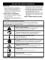
1090r
4-Cycle Gas Trimmer / Brushcutter
OPERATOR’S MANUAL
FOR QUESTIONS, CALL 1-800-345-8746 in U.S. or
1-800-265-6778 in CANADA
www.ryobi.com
IMPORTANT MANUAL
DO NOT THROW AWAY
INTRODUCTION
TABLE OF CONTENTS
THANK YOU
I.
California Emission Regulations . . . . . . . . 3
Thank you for purchasing this quality product.
This modern outdoor power tool is designed to
provide many hours of useful service. You will find
it to be a great labor-saving device.
This operator’s manual provides you with easy-tounderstand operating instructions. Read the entire
manual and follow all of the instructions to keep your
new outdoor power tool in top operating condition.
The other manual that came with your power tool,
the parts manual, contains all of the information that
you need to order parts.
II.
Rules for Safe Operation . . . . . . . . . . . 3-8
A. Important Safety Information . . . . . . 4-6
B. Safety and International Symbols . . . 6-7
C. Know Your Unit . . . . . . . . . . . . . . . . . . 8
PRODUCT REFERENCES, ILLUSTRATIONS
AND SPECIFICATIONS
All information, illustrations and specifications
in this manual are based on the latest product
information available at the time of printing. We
reserve the right to make changes at any time
without notice.
Copyright © 1998 Ryobi Outdoor Products, Inc.
All Rights Reserved.
Bump Head™ is a trademark of Ryobi Outdoor
Products.
Click-Link® is a registered trademark of Ryobi
Outdoor Products.
SERVICE INFORMATION
Service on this unit both within and after the
warranty period should be performed only by
an authorized and approved service dealer.
Dial 1-800-345-8746 in the United States
and 1-800-265-6778 in Canada to obtain
the listing of the authorized service dealer
nearest you.
Do not return the unit to the retailer.
III. Assembly Instructions . . . . . . . . . . . . 9-12
A. Adjusting the J-Handle . . . . . . . . . . . . 9
B. Installing the Harness . . . . . . . . . . . . . 9
C. Removing and Installing the
Cutting Attachment Shield . . . . . . . . . 10
D. Remove the Cutting Blade and
Install the Cutting Attachment . . . . . . 10
E. Removing the Cutting Attachment
and Installing the Cutting Blade . . . . . 11
IV. Oil and Fuel Information . . . . . . . . . . . . . 13
V.
Starting/Stopping Instructions . . . . . . . . 14
VI. Operating Instructions . . . . . . . . . . . 15-17
A. Operating Click-Link System . . . . . . . 15
B. Adjusting Trimming Line Length . . . . . 16
C. Decorative Trimming . . . . . . . . . . . . . 16
D. Edging . . . . . . . . . . . . . . . . . . . . . . . . 16
E. Using the Cutting Blade . . . . . . . . . . . 16
VII. Maintenance and Repair Instructions .17-23
A. Maintenance Schedule . . . . . . . . . . . 17
B. Line Installation . . . . . . . . . . . . . . . . . .18
C. Installing a Prewound Reel . . . . . . . . . 19
D. Air Filter Maintenance . . . . . . . . . . . . 20
E. Carburetor Adjustment . . . . . . . . . . . 21
F. Checking the Oil Level . . . . . . . . . . . . 21
G. Changing the Oil . . . . . . . . . . . . . . . . 22
H. Checking/Adjusting Valve to
Rocker Arm Clearance . . . . . . . . . . . . 22
I. Replacing the Spark Plug . . . . . . . . . 23
VIII. Cleaning and Storage . . . . . . . . . . . . . . .24
A. Accessories/Replacement Parts . . . . 24
IX. Troubleshooting Chart . . . . . . . . . . . . . . 25
NOTE: PROOF OF PURCHASE WILL BE
REQUIRED FOR WARRANTY SERVICE.
X.
Specifications . . . . . . . . . . . . . . . . . . . . 26
XI. Warranty . . . . . . . . . . . . . . . . . . . . . . 27-28
Make sure this manual is carefully read and
understood before starting or operating this
equipment.
THIS PRODUCT IS COVERED BY ONE OR
MORE OF THE US PATENTS LISTED BELOW:
5,241,932; 5,176,116; 4,779,405; 4,651,422;
4,589,742; 4,505,040; 4,463,498; 4,356,605;
4,342,235; 4,223,441; 4,369,742; 5,267,536;
5,243,937; 5,263,454; 5,293,847; 5,558,057;
5,421,292; 5,463,809; 5,564,374; 5,738,062;
Des. 355,198;
OTHER PATENTS PENDING.
2
CONTENTS OF CARTON
This unit should consist of the following:
• Model 1090r with J-Handle and
4-Tooth Cutting Blade with Cover
• String Guard and Hardware
• Bump Head™ String Cutting Attachment
• Shoulder Harness
• Locking Rod
• 3.4 oz. Bottle of 4-Cycle Oil (SAE 30)
• Operator's Manual and Parts Manual
• Product Registration Card
CALIFORNIA EMISSION REGULATIONS
This unit meets the 1995 to 1998 California emissions regulations for small off-road engines. These
units are identified by the label on the engine of your product. A typical identification label is shown.
To ensure that your unit continues to meet these regulations, refer to the following information and
instructions in this operator’s manual.
California Proposition 65 Warning:
WARNING
THE ENGINE EXHAUST FROM THIS
PRODUCT CONTAINS CHEMICALS
KNOWN TO THE STATE OF CALIFORNIA
TO CAUSE CANCER, BIRTH DEFECTS
OR OTHER REPRODUCTIVE HARM.
SPARK ARRESTOR
NOTE: For users on U.S. Forest Land and in the states of California, Maine, Oregon and
Washington. All U.S. Forest Land and the state of California (Public Resources Codes 4442 and 4443),
Oregon and Washington require, by law that certain internal combustion engines operated on forest
brush and/or grass-covered areas be equipped with a spark arrestor, maintained in effective working
order, or the engine be constructed, equipped and maintained for the prevention of fire. Check with
your state or local authorities for regulations pertaining to these requirements. Failure to follow these
requirements could subject you to liability or a fine. This unit is factory equipped with a spark
arrestor. If it requires replacement, ask your LOCAL SERVICE dealer to install the Accessory Part
#182153 Spark Arrestor Kit.
FOR QUESTIONS, CALL 1-800-345-8746 IN U.S. OR 1-800-265-6778 in CANADA
RULES FOR SAFE OPERATION
The purpose of safety symbols is to
attract your attention to possible
dangers. The safety symbols, and their
explanations, deserve your careful
attention and understanding. The safety
warnings do not by themselves eliminate
any danger. The instructions or warnings
they give are not substitutes for proper
accident prevention measures.
SYMBOL
DANGER: Failure to obey a safety
warning will result in serious injury
to yourself or to others. Always
follow the safety precautions to
reduce the risk of fire, electric
shock, and personal injury.
WARNING: Failure to obey a safety
warning can result in serious injury
to yourself or to others.
MEANING
SAFETY ALERT SYMBOL: Indicates
danger, warning, or caution. Special
attention is required in order to avoid
serious personal injury. May be used
in conjunction with other symbols or
pictographs.
CAUTION: Failure to obey a safety
warning may result in property
damage or personal injury to
yourself or to others.
NOTE: Advises you of information or
instructions vital to the operation or
maintenance of the equipment.
3
RULES FOR SAFE OPERATION
• IMPORTANT SAFETY INFORMATION •
READ ALL INSTRUCTIONS
BEFORE OPERATING
• Read the instructions carefully. Be familiar
with the controls and proper use of the unit.
• Do not operate this unit when tired, ill, or
under the influence of alcohol, drugs, or
medication.
• Children and teens under the age of 15 must
not use the unit, except for teens guided by
an adult.
• Inspect the unit before use. Replace
damaged parts. Check for fuel leaks. Make
sure all fasteners are in place and secure.
Replace cutting attachment parts that are
cracked, chipped, or damaged in any way.
Make sure the cutting attachment is properly
installed and securely fastened. Be sure the
cutting attachment shield is properly
attached, and positioned as recommended.
Failure to so can result in personal injury to
the operator and bystanders, as well as
damage to the unit
• Use only 0.095 in (2.41 mm) diameter
genuine Ryobi replacement line. Never use
metal-reinforced line, wire, or rope, etc..
These can break off and become a
dangerous projectile.
• Be aware of the risk of injury to the head,
hands and feet.
• Clear the area to be cut before each use.
Remove all objects such as rocks, broken
glass, nails, wire, or string which can be
thrown or become entangled in the cutting
attachment. Clear the area of children,
bystanders, and pets. At a minimum, keep all
children, bystanders and pets outside a 50 ft.
(15 m.) radius; there still may be a risk to
bystanders from thrown objects. Bystanders
should be encouraged to wear eye
protection. If you are approached, stop the
engine and cutting attachment immediately.
• Squeeze the throttle control and check that it
returns automatically to the neutral position.
Make all adjustments or repairs before using
unit.
SAFETY WARNINGS FOR GAS
TRIMMERS
WARNING: Gasoline is highly flammable, and its
vapors can explode if ignited. Take the following
precautions:
4
• Store fuel only in containers specifically
designed and approved for the storage of
such materials.
• Avoid creating a source of ignition for spilled
fuel. Do not start the engine until fuel vapors
dissipate.
• Always stop the engine and allow it to cool
before filling the fuel tank. Never remove the
cap of the fuel tank, or add fuel, when the
engine is hot. Never operate the unit without
the fuel cap securely in place. Loosen the
fuel tank cap slowly to relieve any pressure in
the tank.
• Mix and add fuel in a clean, well-ventilated
area outdoors where there are no sparks or
flames. Slowly remove the fuel cap only after
stopping engine. Do not smoke while fueling
or mixing fuel. Wipe up any spilled fuel from
the unit immediately.
• Move the unit at least 30 ft. (9.1 m) from the
fueling source and site before starting the
engine. Do not smoke, keep sparks and
open flames from the area while adding fuel
or operating the unit.
WHILE OPERATING
• Never start or run the unit inside a closed
room or building. Breathing exhaust fumes
can kill. Operate this unit only in a well
ventilated area outdoors.
• Wear safety glasses or goggles that are
marked as meeting ANSI Z87.1-1989
standards, and ear/hearing protection when
operating this unit. Wear a face or dust mask
if the operation is dusty. Long sleeve shirts
are recommended.
• Wear heavy, long pants, boots and gloves.
Do not wear loose clothing, jewelry, short
pants, sandals or go barefoot. Secure hair
above shoulder level.
• The cutting attachment shield must always
be in place while operating the unit as a
trimmer. Do not operate unit without both
trimming lines extended, and the proper line
installed. Do not extend the trimming line
beyond the length of the shield.
• This unit has a clutch. The cutting attachment
remains stationary when the engine is idling.
If it does not, have the unit adjusted by an
authorized service technician.
• Adjust the J-handle to your size to provide
the best grip.
RULES FOR SAFE OPERATION
• Be sure the cutting attachment is not in
contact with anything before starting the unit.
• Use the unit only in daylight or good artificial
light.
• Avoid accidental starting. Be in the starting
position whenever pulling the starter rope.
The operator and unit must be in a stable
position while starting. See
Starting/Stopping Instructions.
• Use the right tool. Only use this tool for the
purpose intended.
• Do not overreach. Always keep proper
footing and balance.
• Always hold the unit with both hands when
operating. Keep a firm grip on both the front
and rear handle or grips.
• Keep hands, face, and feet at a distance
from all moving parts. Do not touch or try to
stop the cutting attachment when it is
rotating.
• Do not touch the engine or muffler. These
parts get extremely hot from operation. When
turned off they remain hot for a
short time.
• Do not operate the engine faster than the
speed needed to cut, trim or edge. Do not
run the engine at high speed when not
cutting.
• Always stop the engine when cutting is
delayed or when walking from one cutting
location to another.
• If you strike or become entangled with a
foreign object, stop the engine immediately
and check for damage. Do not operate
before repairing damage. Do not operate the
unit with loose or damaged parts.
• Stop and switch the engine to off for
maintenance, repair, or for changing the
cutting attachment or other attachments.
• Use only genuine Ryobi replacement parts
when servicing this unit. These parts are
available from your authorized service
dealer. Do not use parts, accessories or
attachments not authorized by Ryobi for this
unit. Doing so could lead to serious injury to
the user, or damage to the unit, and void
your warranty.
• Keep unit clean of vegetation and other
materials. They may become lodged
between the cutting attachment and shield.
• To reduce fire hazard, replace faulty muffler
and spark arrestor, keep the engine and
muffler free from grass, leaves, excessive
grease or carbon build up.
WHILE OPERATING WITH
CUTTING BLADE
• Read and understand all safety warnings
before operating this unit.
• Always use the shoulder harness when using
the brush blade accessory.
• Keep the handle between the operator
and cutting attachment or blade at all times.
• NEVER cut with the cutting blade located
over 30 inches (76 cm) or more above the
ground level.
• Blade thrust may occur when the spinning
blade contacts an object that it does not
immediately cut. Blade thrust can be violent
enough to cause the unit and/or operator to
be propelled in any direction , and possibly
lose control of the unit. Blade thrust can
occur without warning if the blade snags,
stalls or binds. This is more likely to occur in
areas where it is difficult to see the material
being cut.
• For operation with the brush blade, do not
cut anything thicker than 1/2 inch or a violent
kickback could occur.
• Do not attempt to touch or stop the blade
when it is rotating.
• A coasting blade can cause injury while it
continues to spin after the engine is stopped
or the throttle trigger is released. Maintain
proper control until the blade has completely
stopped rotating.
• Do not run the unit at high speed when
not cutting.
• If you strike or become entangled with a
foreign object, stop the engine immediately
and check for damage. Have any damage
repaired before attempting further
operations. Do not operate unit with a bent,
cracked or dull blade. Discard blades that
are bent, warped, cracked or broken.
• Do not sharpen the cutting blade.
Sharpening the blade can cause the blade tip
to break off while in use. This can result in
severe personal injury. Replace the blade.
• Stop the engine IMMEDIATELY if you feel
excessive vibration. Vibration is a sign of
trouble. Inspect thoroughly for loose nuts,
bolts or damage before continuing. Repair
or replace affected parts as necessary.
5
RULES FOR SAFE OPERATION
AFTER USE
• Clean cutting blades with a household
cleaner to remove any gum buildup. Oil the
blade with machine oil to prevent rust.
• Lock up and store the cutting blade in an
appropriate area to protect the blade from
unauthorized use or damage.
OTHER SAFETY WARNINGS
• Never store the unit, with fuel in the tank,
inside a building where fumes may reach an
open flame or spark.
• Allow the engine to cool before storing or
transporting. Be sure to secure the unit while
transporting.
• Store the unit in a locked up and dry, or high
and dry place to prevent unauthorized use or
damage. Keep out of the reach of children.
• Never douse or squirt the unit with water or
any other liquid. Keep handles dry, clean and
free from debris. Clean after each use, see
Cleaning and Storage instructions.
• Keep these instructions. Refer to them often
and use them to instruct other users. If you
loan someone this unit, also loan them these
instructions.
SAVE THESE INSTRUCTIONS
SAFETY AND INTERNATIONAL SYMBOLS
This operator's manual describes safety and international symbols and pictographs that
may appear on this product. Read the operator's manual for complete safety, assembly,
operating and maintenance and repair information.
SYMBOL
MEANING
• SAFETY ALERT SYMBOL
Indicates danger, warning, or caution. May be used in
conjunction with other symbols or pictographs.
• READ OPERATOR'S MANUAL
Failure to follow operating instructions and safety precautions
in operator's manual can result in serious injury. Read
operator's manual before starting or operating this unit.
• FOR SERVICE INFORMATION, CALL:
USA: 1-800-345-8746
CANADA: 1-800-265-6778
• WEAR EYE AND HEARING PROTECTION
WARNING: Thrown objects and loud noise can cause severe eye
injury and hearing loss. Wear eye protection meeting ANSI Z87.11989 standards and ear protection when operating this unit.
• KEEP BYSTANDERS AWAY
WARNING: Keep all bystanders, especially children and pets,
at least 50 feet (15 m) away from the trimming area.
• PRIMER BULB
Push primer bulb, fully and slowly, 5 to 7 times.
• UNLEADED FUEL
Always use clean, fresh unleaded fuel.
6
RULES FOR SAFE OPERATION
SYMBOL
MEANING
• INDICATES OIL
Refer to operator's manual for the proper type of oil.
• CHOKE CONTROL
A
B
START position.
RUN position.
• THROWN OBJECTS AND ROTATING CUTTER CAN
CAUSE SEVERE INJURY
WARNING: Do not operate unit without string guard in place.
Keep away from rotating cutter.
• IGNITION SWITCH
ON / START / RUN
• IGNITION SWITCH
OFF or STOP
• HOT SURFACE WARNING
Do not touch a hot muffler, gear box or cylinder. You may get
burned. These parts get extremely hot from operation and
remain hot for a short time after the unit is turned off.
• SHARP BLADE
WARNING: Sharp blade on string guard. To prevent serious
injury, do not touch line cutting blade.
• BRUSHCUTTERS Replace dull blade.
Do not sharpen the brush blade. Sharpening the blade
can cause the blade tip to break off while in use. This
can result in severe personal injury.
• TRIMMER/BRUSHCUTTER SAFETY
WARNING: Thrown objects and rotating cutter can cause
severe injury. Keep bystanders, especially children and pets,
at least 50 feet (15 m) away from the cutting area. Plastic
string guard must be used when using the string cutting head.
7
RULES FOR SAFE OPERATION
KNOW YOUR UNIT
Starter Rope
Grip
Primer
Bulb
Spark Plug
Air Filter
Cover
Handgrip
On/Off Stop
Control
Choke
Lever
Oil Fill
Plug /
Dipstick
Fuel Cap
Throttle
Control
Gear
Housing
J-Handle
Blade
Guard
Shoulder
Harness
4-Tooth
Blade
with Cover
Click-Link
Shaft
Housing
Line Cutting
Blade
Cutting
Attachment
Shield
APPLICATION
Cutting
Attachment
8
Use the string head for cutting light grass and
weeds. Also for decorative trimming around
trees, fences, etc.
Use the 4-tooth brush blade for weeds and light
brush of up to 1/2 inch in diameter.
Other attachments may be used with this unit.
See the list of attachments on page 15.
ASSEMBLY INSTRUCTIONS
ADJUSTING THE J-HANDLE
The J-handle is assembled on this model not
in the correct position. Use the following
instructions to adjust the J-handle to the
correct position.
1. Loosen the four (4) mounting screws
on the J-handle.
2. Slide the J-handle until the arrow/bar on
the decal is flush to the edge of the clamp
assembly (Fig. 1).
3. While holding the unit in the operating
position (Fig. 2), adjust (rotate) the handle
forward and back to a position that
provides you the best grip.
4. Tighten the mounting screws.
INSTALLING THE HARNESS
WARNING: Always use the shoulder
harness when using the cutting
blade to avoid serious personal
injury.
1. Push the strap through the center of the
buckle.
2. Pull the strap over the cross bar and down
through the slot in the buckle (Fig. 3).
3. Snap it on to the support fitting (Fig. 4).
4. Adjust length to fit the operator’s size. Pull
tab to lengthen, pull strap to shorten (Fig 5).
Screws
Decal
Fig. 3
Fig. 1
Fig. 4
Fig. 2
Fig. 5
9
ASSEMBLY INSTRUCTIONS
REMOVING AND INSTALLING
CUTTING ATTACHMENT SHIELD
Remove the cutting attachment shield
when using the unit as a brushcutter.
WARNING: The cutting attachment
shield should NOT be installed when
operating the unit with a blade.
Remove the cutting attachment
shield before removing or installing
the blade.
Remove the cutting attachment shield from the
shield mount by removing the three (3) screws
with a flat blade screwdriver (Fig. 6). Store parts
for future use.
NOTE: To make removing or installing the
cutting blade or cutting attachment
easier, place the unit on the ground or
on a work bench.
1. Install the cutting blade cover. Pull the cover
around the blade and click the plastic lock.
2. Align the shaft bushing hole with the locking
rod slot and insert the locking rod into the
bushing hole (Fig. 7).
Output Shaft
Output Shaft
Bushing
Locking Rod
Screws
Locking Shaft Bushing
Hole
Rod Slot
Fig. 7
3. While holding the locking rod, loosen the nut
on the blade by turning it clockwise with a
5/8 inch closed-end or socket wrench
(Fig. 8).
String Guard
Fig. 6
Install the cutting attachment shield
when using the unit as a grass
trimmer.
WARNING: To avoid serious
personal injury, the cutting
attachment shield SHALL be in
place at all times while operating the
unit as a grass trimmer.
clockwise
Fig. 8
Install the cutting attachment shield on the
shield mount by inserting the three (3) screws
into the shield mount. Tighten securely with a
flat blade screwdriver (Fig. 6).
4. Remove the nut, blade retainer, and blade.
Store the nut and blade together for future
use in a secure place. Store out of reach of
children.
REMOVE THE CUTTING BLADE AND
INSTALL THE CUTTING ATTACHMENT
Install the Cutting Attachment
Remove the Cutting Blade
WARNING: To avoid serious
personal injury, always wear gloves
while handling or installing the blade.
5. Align the shaft bushing hole with the locking
rod slot and insert the locking rod into the
shaft bushing hole. (Fig. 7). Put the blade
retainer onto the output shaft. Screw the
cutting attachment counterclockwise onto
the output shaft. Tighten securely (Fig. 9).
NOTE: The blade retainer must be installed on
the output shaft for the cutting
attachment to work correctly.
10
ASSEMBLY INSTRUCTIONS
Cutting Attachment
Cutting Attachment
Blade Retainer
Locking Rod
Locking Rod Slot
Locking Rod
Fig. 10
Fig. 9
6. Remove the locking rod.
7. Install the cutting attachment shield. See
Removing and Installing Cutting
Attachment Shield, Pg. 10.
WARNING: To avoid serious
personal injury, the cutting
attachment shield SHALL be in
place at all times while operating the
unit as a grass trimmer.
Install the Cutting Blade
WARNING: To avoid serious
personal injury, always wear gloves
while handling or installing the blade.
3. Place the cutting blade on the output shaft
(Fig. 11).
Nut
Blade Retainer
Blade Cover
REMOVING THE CUTTING
ATTACHMENT AND INSTALLING THE
CUTTING BLADE
NOTE: To make removing or installing the
cutting blade or cutting attachment
easier, place the unit on the ground or
on a work bench.
Cutting
Blade
Pilot Hole
Output Shaft
Locking Rod
Remove the Cutting Attachment
Shield
See Removing and Installing Cutting
Attachment Shield, Pg. 10.
Remove the Cutting Attachment
Shield Mount
Fig. 11
4. Center the cutting blade on the pilot step of
the output shaft bushing (Fig. 12).
Output Shaft
WARNING: The gear housing gets
hot with use and can result in injury
to the operator. When the unit is
turned off it remains hot for a short
time. Do not touch the gear housing
until it has cooled.
1. Align the shaft bushing hole with the locking
rod slot and insert the locking rod into the
shaft bushing hole (Fig. 7).
2. While holding the locking rod, remove the
cutting attachment by turning it clockwise off
of the output shaft (Fig. 10). Store the cutting
attachment for future use.
Pilot Step
Output Shaft
Bushing
Fig. 12
11
ASSEMBLY INSTRUCTIONS
5. Make sure that the cutting blade is centered
on the pilot step and sitting flat against the
output shaft bushing (Fig. 13).
WARNING: If the cutting blade is
off-center, the unit will vibrate, and
the blade may fly off, which can
cause serious personal injury.
Pilot Step
Fig. 13
6. Align the shaft bushing hole with the locking
rod slot and insert the locking rod into the
bushing hole (Fig. 7, Pg. 10).
7. Put the blade retainer and nut on the output
shaft. Make sure that the blade is installed
correctly.
8. Tighten counterclockwise against the blade
while holding the locking rod (Fig. 14).
• If using a torque wrench and an 5/8 inch
socket tighten to;
325 - 335 in•lb,
27 - 28 ft.•lb,
37 -38 N•m.
• Without a torque wrench, use a 5/8 inch
closed-end or socket wrench, turning the nut
until the blade retainer is snug against the
shaft bushing. Make sure that the blade is
installed correctly, then rotate the nut an
additional 1/4-1/2 turn counterclockwise
(Fig. 15).
1/4-1/2 turn
Counterclockwise
Fig. 15
9. Remove the locking rod from the locking rod
slot.
WARNING: To avoid serious
personal injury or damage to the
unit, do not start or operate this unit
with the locking rod in the locking rod
slot.
10.Remove the cutting blade cover by
un-snapping the plastic lock on the cover
and pulling it from the blade. Store the cover
for future use.
Counterclockwise
Fig. 14
WARNING: Do not sharpen the
cutting blade. Sharpening the blade
can cause the blade tip to break
off while in use. This can result in
severe personal injury. Replace the
blade.
NOTE: A replacement cutting blade,
Part # 145873 can be purchased from
you local authorized dealer.
12
OIL AND FUEL INFORMATION
RECOMMENDED OIL TYPE
Using the proper type and weight of oil in the
crankcase is extremely important. Check the oil
before each use and change the oil regularly.
Failure to use the correct oil, or using dirty oil,
can cause premature engine wear and failure.
Use a high-quality SAE 30 weight oil of
API (American Petroleum Institute) service class
SG, SF, SH.
ADDING OIL TO CRANKCASE –
INITIAL USE
Your unit is supplied with one bottle of oil,
3.4 fluid oz (100 ml) SAE 30 SF, SG, SH (Fig. 16).
1. Open the bottle of oil.
2. Install the funnel spout.
3. Place the unit on a flat level surface.
4. Remove the oil plug / dipstick from the
crankcase. Pour the entire bottle of oil into
the crankcase (Fig. 17).
NOTE: Save the bottle and spout for future
use.
NOTE: Never add oil to the fuel or fuel tank.
5. Wipe up any oil that may have spilled and
reinstall the oil fill plug / dipstick.
The importance of checking and maintaining
the proper oil level in the crankcase cannot be
overemphasized. Check oil before each use
and change as needed as shown in
Maintenance section.
Funnel Spout
Fig. 16
RECOMMENDED FUEL TYPE
WARNING: Gasoline is extremely
flammable and its vapors can
explode if they are ignited. To avoid
serious personal injury, always stop
the engine and allow it to cool
before filling the fuel tank. Do not
smoke while filling the tank. Keep
sparks and open flames away from
the area.
WARNING: Pressure can build up
in the fuel tank. Loosen the fuel
tank cap slowly to relieve any
pressure in the tank.
Old fuel is usually the main reason for the unit
not running properly. Be sure to use fresh,
clean, unleaded fuel.
NOTE: Alcohol-blended fuel absorbs moisture
(water). As little as 1% moisture in the
fuel can cause it to separate and form
acids when stored. If this type of fuel
must be used, use fresh fuel (less than
60 days old).
DEFINITION OF BLENDED FUELS
Today's fuels are often a blend of gasoline and
one or more oxygenates such as ethanol,
methanol or MTBE (ether).
USE OF BLENDED FUELS
If you choose to use a blended fuel or its use is
unavoidable, the following precautions are
recommended.
1. Always use fresh unleaded fuel per your
operator's manual.
2. Use the special additive STA-BIL® or
an equivalent.
3. Always agitate the fuel mix before fueling
the unit.
4. Drain the tank and run the engine dry before
storing the unit.
USE OF FUEL ADDITIVES
The use of fuel additive, such as STA-BIL® Gas
Stabilizer or an equivalent, will inhibit corrosion
and minimize the formation of gum deposits.
Add 0.8 oz (23 ml) per gallon of fuel per
instructions on container. NEVER add fuel
additives directly to the unit's fuel tank. Using
a fuel additive can keep fuel fresh for up to
six (6) months.
Fig. 17
13
STARTING/STOPPING INSTRUCTIONS
STARTING/STOPPING
WARNING: Operate this unit only
in a well-ventilated area outdoors.
Carbon monoxide exhaust fumes can
be lethal in a confined area.
WARNING: Avoid accidental starting.
Be in the starting position whenever
pulling the starting rope. To avoid
serious personal injury, the operator
and unit must be in a stable position
while starting.
NOTE: Keep the throttle control depressed at
all times until the engine is warmed up.
1. Check oil level in crankcase. See Checking
the Oil Level in Maintenance section.
2. Fill the fuel tank with fresh, clean, unleaded
fuel (see page 13).
3. Put the On/Off Stop Control in the START [I]
position (Fig. 18).
4. Fully press and release the primer bulb slowly
5 to 7 times. Fuel should be visible in the
bulb (Fig. 19).
5. Place the choke lever in the START (A)
position (Fig. 19).
6. With the unit in the starting position, squeeze
the throttle control and pull the starter rope
briskly until the engine sounds like it wants to
run (normally 2 to 5 pulls) (Fig. 20).
7. Place the choke lever in the RUN (B) position
(Fig. 19). The lever should snap up into place.
8. Pull the starter rope briskly 1 to 3 times to
start the engine (Fig. 20).
9. If the engine does not start, repeat steps
5 through 8.
NOTE: If the engine floods while attempting
to start the unit, place the choke lever
in the RUN (B) position, squeeze the
throttle control, and pull the starter
rope briskly. The engine should start
within three (3) to eight (8) pulls.
10.Keep throttle control depressed for 5 to 10
seconds to warm up engine.
NOTE: Choking is not required when starting a
warm engine. Start a warm engine
with the On/Off Stop Control in the
START position and the choke lever
in the RUN (B) position.
11.To stop the engine, put the On/Off Stop
Control in the STOP [O] position (Fig. 18).
14
On/Off Stop
Control
Fig. 18
Choke
Lever
Run
(B)
Primer
Bulb
Start
(A)
Fig. 19
Starter
Rope
Throttle
Control
Fig. 20
OPERATING INSTRUCTIONS
OPERATING THE CLICK-LINK®
SYSTEM
This unit is equipped with a Click-Link® System,
which enables optional attachments to be
installed on the unit. The optional attachments
are:
Blower/Vacuum . . . . . . . . . . . . . . . . . . BV720r
Cultivator . . . . . . . . . . . . . . . . . . . . . . . GC720r
Edger . . . . . . . . . . . . . . . . . . . . . . . . . . LE720r
Hedge Trimmer . . . . . . . . . . . . . . . . . . HS720r
Snow Thrower . . . . . . . . . . . . . . . . . . . ST720r
Straight Shaft Trimmer . . . . . . . . . . . . . SS725r
Sweeper/Blower . . . . . . . . . . . . . . . . . . SB720r
Tree Pruner . . . . . . . . . . . . . . . . . . . . . . TP720r
Turbo Blower . . . . . . . . . . . . . . . . . . . . TB720r
WARNING: To avoid serious
personal injury, shut off the unit
prior to removing or installing
any attachments.
Removing the Lower (Attachment) Boom
NOTE: To make removing the boom easier,
place the unit on the ground or on
a workbench.
1. Loosen the knob counterclockwise (Fig. 21).
2. Press and hold the release button in (Fig. 21).
3. While firmly holding the upper boom, pull
the lower boom straight out of the Click-Link
(Fig. 22).
Click-Link
Release Button
NOTE: Aligning the release button with guide
recess will help installation (Fig. 21).
2. Basic trimming or using other Ryobi
attachments - Locate and lock the release
button into the primary hole in the Click-Link
(Fig. 22).
3. Edging with the trimmer head attachment
- Locate and lock the release button into the
90˚ edging hole or 180˚ edging hole in the
Click-Link (Fig. 23).
CAUTION: Make sure the release
button is locked in the primary hole
and knob is securely tightened
before operating this unit.
CAUTION: All attachments are
designed to be used in the primary
hole unless otherwise indicated in
the attachment’s operator’s manual.
If the incorrect hole is used, it
could result in injury, or damage
to the unit.
4. Tighten the knob securely clockwise before
using the unit (Fig. 23).
Click-Link
Upper
Boom
Primary Hole
Release
Button
Lower
Boom
Fig. 22
Guide
Recess
Knob
90˚
Edging
Hole
Knob
Fig. 21
180˚
Edging
Hole
If your unit is not assembled, or you
have more than one attachment, use
the following instructions:
Installing the Lower (Attachment) Boom
Fig. 23
1. Remove the hanger from the lower
(attachment) boom. Hold the release button
in while pushing the lower (attachment)
boom into the Click-Link (Fig. 22).
15
OPERATING INSTRUCTIONS
ADJUSTING TRIMMING LINE LENGTH
EDGING
Your unit is equipped with a string head that
allows the operator to release more trimming
line without stopping the engine. To release
additional line, lightly tap the string head on
the ground (Fig. 24) while operating the unit at
high speed.
For edging with the trimming head attachment,
locate and lock the release button into the
90° edging hole or 180° edging hole in the
Click-Link system (Fig. 23, Pg. 15).
NOTE: Always keep the trimming line fully
extended. Line release becomes
more difficult as cutting line
becomes shorter.
USING THE CUTTING BLADE
WARNING: Do not sharpen the
cutting blade. Sharpening the blade
can cause the blade tip to break
off while in use. This can result in
severe personal injury to yourself
or others.
WARNING: Always wear eye,
hearing, foot, and body protection
to reduce the risk of injury when
operating this unit.
Always use the proper stance for using the
brush blade (Fig. 26).
Fig. 24
Each time the head is bumped, about 1 inch
(25.4 mm) of trimming line is released. A blade
in the string guard will cut the line to the proper
length if excess line is released.
CAUTION: Do not remove or alter
the line cutting blade assembly.
Excessive line length will cause
clutch to over-heat and may result
in serious personal injury.
For best results, tap the head on bare ground
or hard soil. If line release is attempted in tall
grass, the engine may stall.
DECORATIVE TRIMMING
Decorative trimming is accomplished by
removing all vegetation around trees, posts,
fences, etc.
Rotate the entire unit so that the cutting head
is at a 30° angle to the ground (Fig. 25).
Fig. 26
WARNING: The blade continues to
spin after the engine is turned off.
The coasting blade can seriously cut
you if accidentally touched.
Do not clear away cut material with
the engine running or blade turning.
Fig. 25
16
To avoid serious personal injury, turn
off engine and allow the blade to
stop before removing materials
wrapped around the blade shaft.
OPERATING INSTRUCTIONS
Cutting Blade Operating Tips:
To establish a rhythmic cutting procedure:
• Plant feet firmly, comfortably apart.
• Bring the engine to full throttle before
entering the material to be cut. The blade
has maximum cutting power at full throttle
and is less likely to bind, stall, or cause
blade thrust, which can result in serious
personal injury to the operator or others.
• Cut while swinging the upper part of your
body from right to left.
• Always release the throttle trigger and allow
the engine to return to idle speed when not
cutting. Swing the unit in the same direction
as the blade spins, which increases the
cutting action.
• Move forward to the next area to be cut after
the return swing and plant feet again.
• The brush blade is designed with a second
set of teeth, which can be used by removing
the blade, turning it upside down, and
reinstalling it.
To reduce the chance of material wrapping
around the blade, follow these steps:
• Cut at full throttle.
• Swing the unit into material to be cut from
your right to your left (Fig. 27).
• Avoid the material just cut as you make the
return swing.
WARNING: Blade thrust may occur
when the spinning blade contacts an
object that it does not immediately
cut. Blade thrust can be violent
enough to cause the unit and/or
operator to be propelled in any
direction, and possibly lose control
of the unit. Blade thrust can occur
without warning if the blade snags,
stalls or binds. This is more likely to
occur in areas where it is difficult to
see the material being cut.
Fig. 27
MAINTENANCE AND REPAIR INSTRUCTIONS
MAINTENANCE SCHEDULE
These required maintenance procedures should
be performed at the frequency stated in the
table. They should also be included as part of
any seasonal tune-up.
For a new engine, change the oil after the first
10 hours of operation. See Changing the Oil
(Pg. 22).
WARNING: To prevent serious
personal injury, never perform any
type of maintenance or repairs with
the unit running or while it is hot.
Allow the unit to cool down.
Disconnect spark plug wire to
make sure the unit will not start.
FREQUENCY
MAINTENANCE REQUIRED
REFER TO:
Daily or Before
Starting Engine
Check oil level.
Fill fuel tank with correct type of fuel.
Page 21
Page 13
Every 10 Hours
Clean and re-oil air filter.
Page 20
Every 25 Hours
Change oil.
Page 22
Every 50 Hours
Check spark plug condition and gap.
Page 23
Every 50 Hours
Check rocker arm to valve clearance
and adjust as required
Page 22
17
MAINTENANCE AND REPAIR INSTRUCTIONS
LINE INSTALLATION
The trimming line may be replaced by two
different methods - rewinding the existing reel or
installing a prewound reel.
Rewinding the Existing Reel
To rewind the existing reel you must:
1. Check for the correct line size.
2. Remove the existing reel and spring.
3. Wind the existing reel with the new line.
4. Reinstall the existing reel and spring.
The Correct Line to Use
WARNING: Always use genuine
Ryobi replacement line. Do not use
metal-reinforced line.
Fig. 29
4. Check the indexing teeth on the inner
reel and outer spool for wear (Fig. 30).
If necessary, remove burrs or replace
the reel and spool.
It is very important to use the correct size line.
Use line with a diameter of 0.095 in (2.41 mm).
The motor may overheat and fail if you use a
larger line.
Removing the Existing Reel
1. Hold the outer spool with one hand and
unscrew the Bump Knob™ clockwise
(Fig. 28). Inspect the captured bolt inside
the Bump Knob to make sure it moves freely.
Replace the Bump Knob if it is damaged.
2. Remove the inner reel and spring (Fig. 28).
Fig. 30
Winding the Existing Reel
1. Take approximately 30 feet (9 m) of new
trimming line, loop it into two equal lengths.
Insert each end of the line through one of the
two holes in the inner reel (Fig. 31).
Pull the line so that the loop is as small
as possible.
Spring
Inner Reel
Bump Knob
Loop
Fig. 28
3. Use a clean cloth to clean the inner surface
of the outer spool (Fig. 29).
NOTE: Always clean the inner reel, outer
spool, and shaft before reassembling
the cutting head.
18
Fig. 31
MAINTENANCE AND REPAIR INSTRUCTIONS
2. Wind the lines, in even and tight layers,
onto the reel (Fig. 32). Wind the line in the
direction indicated on the inner reel. Be sure
not to overlap the two ends of the line.
Reinstalling the Reel
1. Insert the ends of the line through the eyelets
in the outer spool and place inner reel inside
the outer spool (Fig. 34). Then grasp the
ends and pull firmly to release the line from
the holding slots in the spool.
NOTE: The spring must be assembled on
the inner reel before reassembling
the string head.
Fig. 32
NOTE: Place your index finger between
the two lines to stop the lines from
overlapping.
NOTE: Failure to wind the line in the direction
indicated will cause the cutting head
to operate incorrectly.
3. Insert the ends of the line into the two
holding slots (Fig. 33).
Fig. 34
2. Hold the inner reel in place and install
the Bump Knob in the counterclockwise
direction (see Fig. 28). Line installation
is now complete.
INSTALLING PREWOUND REEL
1. Follow the instructions in The Correct Line
to Use.
2. Follow the instructions in Removing the
Existing Reel.
3. Follow the instructions in Reinstalling the
Reel.
Fig. 33
19
MAINTENANCE AND REPAIR INSTRUCTIONS
AIR FILTER MAINTENANCE
Clean and re-oil the air filter every 10 hours
of operation. Your unit’s air filter is one of the
most important areas to maintain. If it is not
maintained, you will void the warranty. Before
cleaning, make sure the unit is turned off.
1. Place the choke lever in the RUN (B)
position (Fig. 35).
2. Remove the carburetor/air filter cover by
pulling up the two tabs on the bottom back
of the cover, then pull out and up (Fig. 35).
3. Remove the air filter (Fig. 35).
Carburetor/
Air Filter
Cover
Air Filter
Choke Lever
5. Apply enough clean SAE 30 motor oil to
lightly coat the filter (Fig. 37).
Fig. 37
6. Squeeze the filter to spread and remove
excess oil (Fig. 38).
7. Reinstall the filter (Fig.35).
Fig. 38
Tab
Slots
Fig. 35
4. Wash the filter in detergent and water
(Fig. 36). Rinse the filter thoroughly
and allow it to dry.
8. Reinstall the air filter cover by positioning the
notch on top of the air filter cover onto the
tab at the top of the back plate. Be sure the
choke lever in the RUN (B) position (Fig. 39).
9. Using two fingers on either side of the air
filter cover and back plate, squeeze together
until the cover snaps into place (Fig. 39).
NOTE: If the unit is operated without the
carburetor/air filter cover assembled,
you will VOID the warranty.
Back Plate
Carburetor/
Air Filter
Cover
Fig. 36
Tab
Fig. 39
20
Slots
MAINTENANCE AND REPAIR INSTRUCTIONS
CARBURETOR ADJUSTMENT
This unit is equipped with a diaphragm-type, fixed
jet carburetor that has been carefully calibrated at
the factory. In most cases, no further adjustment
is required.
Old fuel is usually the main reason for the
unit not running properly. Drain and refill the
tank with clean, fresh unleaded fuel prior to
doing any adjustments.
The condition of the air filter is important to the
operation of the unit. A dirty air filter will restrict
the air flow, which upsets the fuel-air mixture in
the carburetor. The resulting symptoms are often
mistaken for an out-of-adjustment carburetor.
Therefore, check the condition of the air filter
before adjusting the carburetor. Refer to Air Filter
Maintenance.
If the following conditions are experienced, it may
be necessary to adjust the carburetor:
• The engine will not idle
• The engine hesitates or stalls on acceleration
• A loss of engine power that is not corrected
by new fuel or cleaning the air filter
NOTE: Warm up the engine for 30-60
seconds before adjusting the
carburetor.
1. Clean the air filter if it is dirty. Refer to Air
Filter Maintenance.
2. Fill the tank with clean, unleaded fuel.
3. If the engine stops frequently when idling,
turn the idle speed screw clockwise 1/2 turn
until the engine stabilizes (Fig. 40).
4. If the cutting head keeps rotating after the
trigger is released, turn the idle speed screw
counterclockwise 1/2 turn until the head
stops rotating (Fig. 40).
If the unit will still not run properly, take it to an
authorized service dealer.
CHECKING THE OIL LEVEL
CAUTION: To prevent extensive
engine wear and damage to the unit,
always maintain the proper oil level
in the crankcase. Never operate the
unit with the oil level below the
bottom of the dipstick.
The importance of checking and maintaining
the proper oil level in the crankcase cannot be
overemphasized. Check oil before each use
as follows:
1. Make sure the engine is stopped and is cool
so the oil has had time to drain into the
crankcase.
2. Place the unit on a flat, level surface to get a
proper oil level reading.
3. To keep dirt, grass clippings, etc., out of the
engine, clean the area around the oil fill
plug / dipstick before removing it.
4. Remove the oil fill plug / dipstick and wipe
the oil off. Reinsert it all the way back in.
5. Remove the oil fill plug / dipstick and check
the oil level. The level should be up to the
top of the dipstick (Fig. 41).
6. If the level is low, add a small amount of oil
to the crankcase and recheck. Continue to
do this until the oil level reaches the top of
the dipstick (Fig. 42).
NOTE: Be careful not to overfill the unit.
Oil Fill
Plug /
Dipstick
Idle Adjustment
Screw
Fig. 41
O-Ring
Top of
Dipstick
Oil Fill
Plug /
Dipstick
Fig. 40
Fig. 42
21
MAINTENANCE AND REPAIR INSTRUCTIONS
CHANGING THE OIL
For a new engine, change the oil after the first
10 hours of operation. Thereafter, change the
oil after every 25 hours or before storing the
unit for an extended period of time.
It is best to change the oil while the engine is
still warm. The oil will flow freely and carry away
more impurities.
CAUTION: Wear gloves to prevent
injury when handling the unit.
Change the oil as follows:
1. Remove the oil fill plug / dipstick.
2. Pour the oil into a container by tipping the
unit to a vertical position (Fig. 43). Be sure
to allow ample time for complete drainage.
3. Wipe up any oil residue on the unit and clean
up any oil that may have spilled. Dispose of
the oil according to Federal, State and local
regulations.
4. Refill the crankcase with 3.4 fluid oz (100 ml)
of SAE 30 SF, SG, SH oil. Use the bottle and
spout from initial use.
5. Reinstall the oil fill plug /dipstick.
CHECKING / ADJUSTING VALVE TO
ROCKER ARM CLEARANCE
Every 50 hours of operation, inspect the
valve to rocker arm clearance using a flat
feeler gauge.
NOTE: This requires some disassembly of
the engine. If you feel unsure or
unqualified to perform this, take the
unit to an authorized service center.
NOTE: The engine must be cold when
checking or adjusting the valve
clearance.
This task should be performed inside, in a
clean, dust free area.
1. Loosen the two (2) screws shown in figure 44.
2. Remove the three (3) screws that secure the
engine cover (Figs. 44 and 45).
Screws to
Remove
Screws to
Loosen
NOTE: Make sure the O-ring is in place on the
oil fill plug / dipstick when checking
and changing the oil (Fig. 42, Pg. 21).
Fig. 44
Screw to
Remove
Back of Engine
Fig. 45
Fig. 43
22
MAINTENANCE AND REPAIR INSTRUCTIONS
3. Disconnect the spark plug wire.
4. Remove the spark plug and then remove
the engine cover.
5. Remove the rocker arm cover and gasket
(Fig. 46).
6. While looking in the spark plug hole, pull the
starter rope slowly and bring the piston to
the top position. Check that both rocker
arms should move freely. If they do not,
repeat this step. This will be the top of the
compression stroke.
Feeler
Gauge
Rocker Arm
Adjusting Nut
Gasket
Fig. 47
Rocker Arm
Cover
REPLACING THE SPARK PLUG
Fig. 46
7. Using a flat feeler gauge, measure the
clearance between the valve stems and
rocker arms (Fig 47).
The recommended clearance for both intake
and exhaust is .003–.006 in. (0.076–0.0152 mm).
The feeler gauge should slide between the
rocker arm and valve stem with a slight
amount of resistance, without binding.
8. If the clearance is not within specification,
adjust as follows:
a. Turn the adjusting nut using a 5/16 inch
(8 mm) wrench or nut driver (Fig. 47).
Use a Champion RDZ19H spark plug
(or equivalent). Correct air gap is 0.025 in.
(0.655 mm). Remove plug after every 50 hours
of operation and check its condition.
1. Stop the engine and allow it to cool. Pull the
wire off of the spark plug.
2. Clean around the spark plug and remove it
from the cylinder head. Use a 5/8 inch
socket to remove the plug.
CAUTION: Replace a cracked,
fouled or dirty spark plug. Do not
sand blast, scrape, or clean
electrodes because the engine
could be damaged by grit entering
the cylinder.
3. Set the air gap at 0.025 in. (0.655 mm)
using a wire feeler gauge (Fig. 48). Install
a correctly gapped spark plug into the
cylinder head. Torque to 100-110 in•lb
(11.3-12.3 N•m).
To increase the clearance, turn the
adjusting nut counterclockwise.
To decrease the clearance, turn the
adjusting nut clockwise.
b. Recheck both valve clearances and adjust
as necessary.
9. Reinstall the rocker arm cover using a new
gasket. Torque the screw to 20–30 in•lb
(2.2–3.4 N•m).
10.Reinstall the engine cover. Check alignment
of the cover before tightening the screws.
Be sure to tighten the screws loosened
in step 1.
11.Check the spark plug, see Replacing the
Spark Plug, and reinstall. Torque the spark
plug to 100–110 in•lb (11.3–12.3 N•m).
Reinstall the spark plug wire.
0.025 inch
(0.655 mm)
Fig. 48
23
CLEANING AND STORAGE
CLEANING
WARNING: Always turn off your
trimmer before you clean or perform
any maintenance on it.
Use a small brush to clean off the outside of the
unit. Do not use strong detergents on plastic
housing or handle. They can be damaged by
household cleaners that contain aromatic oils
such as pine and lemon, and by solvents such
as kerosene. Wipe off any moisture with a soft
cloth.
STORAGE
If the unit will be stored for an extended period
of time, use the following storage procedure.
1. Drain all fuel from the fuel tank into a
container. Do not use fuel that has been
stored for more than 60 days. Dispose
of the old fuel in accordance to Federal,
State and Local regulations.
2. Start the engine and allow it to run until it
stalls. This ensures that all fuel has been
drained from the carburetor.
3. Allow the engine to cool. Remove the spark
plug and put approximately 1 oz (30 ml) of
any high quality motor oil or 4-cycle oil into
the cylinder. Pull the starter rope slowly to
distribute the oil. Reinstall the spark plug.
24
4. Thoroughly clean the unit and inspect for any
loose or damaged parts. Repair or replace
damaged parts and tighten loose screws,
nuts or bolts. The unit is now ready for
storage.
5. To prevent unauthorized use or damage, lock
up and store the unit in a dry, well-ventilated
area.
NOTE: Remove the spark plug and drain
all of the oil from the cylinder before
attempting to start the trimmer after
storage.
ACCESSORIES/REPLACEMENT
PARTS
4-Cycle Oil . . . . . . . . . . . . . . . . . . . . . .181786
Oil Fill Plug / Dipstick . . . . . . . . . . . . . .181975
Spark Plug . . . . . . . . . . . . . . . . . . . . . . 180852
Spark Arrestor . . . . . . . . . . . . . . . . . . . 182153
Replacement Line Cartridge . . . . . . . . . 147345
Inner Reel Spring . . . . . . . . . . . . . . . . . 610636
Bump Head Knob Assembly . . . . . . . . 180814
Fuel Cap . . . . . . . . . . . . . . . . . . . . . . . 181083
Shoulder Harness . . . . . . . . . . . . . . . . 682075
Click-Link Coupler . . . . . . . . . . . . . . . 181616
TROUBLESHOOTING
PROBLEM
Engine will not start
Engine will not idle
Engine will not accelerate
Engine lacks power or
stalls when cutting
Engine rope is difficult to
pull or engine locks
CAUSE
ACTION
On/Off Stop Control is in the
STOP position
Turn On/Off Stop Control to the
START position
Empty fuel tank
Fill fuel tank
Primer bulb wasn't pressed
enough
Press primer bulb fully and slowly
5-7 times
Engine flooded
Use starting procedure WITHOUT
choke lever in the START position
Old Fuel
Drain fuel tank / Add fresh fuel
Fouled spark plug
Replace or clean spark plug
Air Filter is Plugged
Replace or clean air filter
Old Fuel
Drain fuel tank / Add fresh fuel
Old Fuel
Drain fuel tank / Add fresh fuel
Carburetor misadjusted
Adjust carburetor
Cutting head bound with grass
Stop engine and clean cutting
head
Dirty air filter
Clean or replace air filter
Old Fuel
Drain fuel tank / Add fresh fuel
Cutting head bound with grass
Stop engine and clean cutting
head
Muffler or spark arrestor
plugged
Clean or replace muffler / spark
arrestor (contact authorized
service dealer)
Unit operated with low or no
oil. Oil accumulated in
combustion chamber
Check oil level before starting
1. Remove spark plug
2. Drain any oil from the spark
plug hole.
3. Pull the starter rope several
times to remove any excess oil
from the cylinder
4. Clean, inspect and reinstall
spark plug, replace if necessary
5. Check oil level before starting
Cutting head will not
advance line
Cutting head out of line
Refill with new line
Inner reel bound up
Replace inner reel
Cutting head dirty
Clean inner reel and outer spool
Line welded
Disassemble, remove the welded
section and rewind the line
Line twisted when refilled
Disassemble and rewind line
Not enough line is exposed
Push the Bump Knob and pull out
line until 4 in (102 mm) of line is
outside of the cutting head
If further assistance is required, contact your authorized service dealer.
25
SPECIFICATIONS
ENGINE
Engine Type . . . . . . . . . . . . . . . . . . . . . . . . . . . . . . . . . . . . . . . . . . . . . . . . . . . . . Air-Cooled, 4-Cycle
Displacement . . . . . . . . . . . . . . . . . . . . . . . . . . . . . . . . . . . . . . . . . . . . . . . . . . . . 1.6 cu. in. (26.2 cc)
Clutch Type . . . . . . . . . . . . . . . . . . . . . . . . . . . . . . . . . . . . . . . . . . . . . . . . . . . . . . . . . . . . Centrifugal
Operating RPM (Trimmer) . . . . . . . . . . . . . . . . . . . . . . . . . . . . . . . . . . . . . . . . . . . . . 8,000-8,500 rpm
Operating RPM (Brushcutter) . . . . . . . . . . . . . . . . . . . . . . . . . . . . . . . . . . . . . . . . . . 8,900-9,500 rpm
Idle Speed RPM . . . . . . . . . . . . . . . . . . . . . . . . . . . . . . . . . . . . . . . . . . . . . . . . . . . . 2,800-3,300 rpm
Ignition Type . . . . . . . . . . . . . . . . . . . . . . . . . . . . . . . . . . . . . . . . . . . . . . . . . . . . . . . . . . . . . Electronic
Ignition Switch . . . . . . . . . . . . . . . . . . . . . . . . . . . . . . . . . . . . . . . . . . . . . . . . . . . . . . . . Toggle Switch
Spark Plug Gap . . . . . . . . . . . . . . . . . . . . . . . . . . . . . . . . . . . . . . . . . . . . . . . . 0.025 inch (0.655 mm)
Lubrication . . . . . . . . . . . . . . . . . . . . . . . . . . . . . . . . . . . . . . . . . . . . . . . . . . . . . . . . . . . . . SAE 30 Oil
Crankcase Oil Capacity . . . . . . . . . . . . . . . . . . . . . . . . . . . . . . . . . . . . . . . . . . . . . . . . . 3.4 oz (100 ml)
Fuel . . . . . . . . . . . . . . . . . . . . . . . . . . . . . . . . . . . . . . . . . . . . . . . . . . . . . . . . . . . . . . . . . . . Unleaded
Carburetor . . . . . . . . . . . . . . . . . . . . . . . . . . . . . . . . . . . . . . . . . . . . . . . . . . . . Diaphragm, All-Position
Starter . . . . . . . . . . . . . . . . . . . . . . . . . . . . . . . . . . . . . . . . . . . . . . . . . . . . . . . . . . . . . . . Auto Rewind
Muffler . . . . . . . . . . . . . . . . . . . . . . . . . . . . . . . . . . . . . . . . . . . . . . . . . . . . . . . . . . Baffled with Guard
Throttle . . . . . . . . . . . . . . . . . . . . . . . . . . . . . . . . . . . . . . . . . . . . . . . . . . . . . . . Manual Spring Return
Fuel Tank Capacity . . . . . . . . . . . . . . . . . . . . . . . . . . . . . . . . . . . . . . . . . . . . . . . . . . . . 20 oz (591 ml)
Fuel Tank . . . . . . . . . . . . . . . . . . . . . . . . . . . . . . . . . . . . . . . . . . . . . . . . . . . . . . . . . . HD Polyethylene
DRIVE SHAFT & CUTTING HEAD
Drive Shaft Housing . . . . . . . . . . . . . . . . . . . . . . . . . . . . . . . . . . . . . . . . . . Aluminum Tube (Click-Link)
Throttle Control . . . . . . . . . . . . . . . . . . . . . . . . . . . . . . . . . . . . . . . . . . . . . . . . . . . . . Finger-Tip Trigger
Unit Weight (No Fuel, with J-handle, Cutting attachment shield
and Cutting attachment) . . . . . . . . . . . . . . . . . . . . . . . . . . . . . . . . . . . . . . . . . . . . . . 13.5 lbs (6.13 kg)
Cutting Mechanism . . . . . . . . . . . . . . . . . . . . . . . . . . . .Dual String Cutting Head, 4-Tooth Brush Blade
Blade Diameter . . . . . . . . . . . . . . . . . . . . . . . . . . . . . . . . . . . . . . . . . . . . . . . . . . . 8 inches (204 mm)
Shoulder Strap . . . . . . . . . . . . . . . . . . . . . . . . . . . . . . . . . . . . . . . . . . . . . . . . . . . . Single Quick-Snap
Line Spool . . . . . . . . . . . . . . . . . . . . . . . . . . . . . . . . . . . . . . . . . . . . . . . . . . . . . . Bump Line Releaser
Line Spool Diameter . . . . . . . . . . . . . . . . . . . . . . . . . . . . . . . . . . . . . . . . . . . . . . 4 inches (101.6 mm)
Trimming Line Diameter . . . . . . . . . . . . . . . . . . . . . . . . . . . . . . . . . . . . . . . . . 0.095 inches (2.41 mm)
Cutting Path Diameter . . . . . . . . . . . . . . . . . . . . . . . . . . . . . . . . . . . . . . . . . . . . . 18 inches (44.0 cm)
Gear Box Ratio . . . . . . . . . . . . . . . . . . . . . . . . . . . . . . . . . . . . . . . . . . . . . . . . . . . . . . . . . . . . . 1.23:1
26
CALIFORNIA EMISSION CONTROL WARRANTY STATEMENT
YOUR WARRANTY RIGHTS AND OBLIGATIONS
The California Air Resources Board and Ryobi
Outdoor Products (ROP), are pleased to explain
the emission control system warranty on your
1995 and later small off-road engine. In
California, new small off-road engines must
be designed, built and equipped to meet the
State's stringent anti-smog standards. ROP
must warrant the emission control system on
your small off-road engine for the periods of
time listed below provided there has been no
abuse, neglect or improper maintenance of
your small off-road engine.
Your emission control system may include parts
such as the carburetor or fuel injection system,
the ignition system, and catalytic converter. Also
included may be hoses, belts, connectors and
other emission-related assemblies.
MANUFACTURER'S WARRANTY COVERAGE:
• The warranty period begins on the date the
engine or equipment is delivered to the retail
purchaser.
•
The manufacturer warrants to the initial owner
and each subsequent purchaser, that the
engine is free from defects in material and
workmanship which cause the failure of a
warranted part for a period of two years.
•
Repair or replacement of warranted part will
be performed at no charge to the owner at
an Authorized Ryobi Service Center. For the
nearest location, please contact Ryobi at:
1-800-345-8746.
•
Any warranted part which is not scheduled for
replacement, as required maintenance which
is scheduled only for regular inspection to the
effect of "Repair or replace as necessary" is
warranted for the warranty period. Any
warranted part which is scheduled for
replacement as required maintenance will be
warranted for the period of time up to the first
scheduled replacement point for that part.
•
The owner will not be charged for diagnostic
labor which leads to the determination that a
warranted part is defective, if the diagnostic
work is performed at an Authorized Ryobi
Service Center.
•
The manufacturer is liable for damages to
other engine components caused by the
failure of a warranted part still under warranty.
•
Failures caused by abuse, neglect or improper
maintenance are not covered under warranty.
•
The use of add-on or modified parts can be
grounds for disallowing a warranty claim. The
manufacturer is not liable to cover failures or
warranted parts caused by the use of add-on
or modified parts.
•
In order to file a claim, go to your nearest
Authorized Ryobi Service Center. Warranty
services or repairs will be provided at all
Authorized Ryobi Service Centers.
•
Any manufacturer approved replacement part
may be used in the performance of any
warranty maintenance or repair of emission
related parts and will be provided without
charge to the owner. Any replacement part
that is equivalent in performance or durability
may be used in non-warranty maintenance or
repair and will not reduce the warranty
obligations of the manufacturer.
•
The following components are included in the
emission related warranty of the engine, air
filter, carburetor, primer, fuel lines, fuel pick
up/fuel filter, ignition module, spark plug and
muffler.
Where a warrantable condition exists, ROP will
repair your small off-road engine at no cost to
you including diagnosis, parts and labor.
The 1995 and later small off-road engines are
warranted for two years. If any emission-related
part on your engine is defective, the part will
be repaired or replaced by ROP.
OWNER'S WARRANTY RESPONSIBILITIES:
•
•
•
As the small off-road engine owner, you are
responsible for the performance of the
required maintenance listed in your
operator's manual. ROP recommends that
you retain all receipts covering maintenance
on your small off-road engine, but ROP
cannot deny warranty solely for the lack of
receipts or for your failure to ensure the
performance of all scheduled maintenance.
As the small off-road engine owner, you
should however be aware that ROP may
deny you warranty coverage if your small
off-road engine or a part has failed due to
abuse, neglect, improper maintenance or
unapproved modifications.
You are responsible for presenting your
small off-road engine to a Ryobi Authorized
Service Center as soon as a problem exists.
The warranty repairs should be completed in
a reasonable amount of time, not to exceed
30 days.
If you have any questions regarding your
warranty rights and responsibilities, you
should call 1-800-345-8746.
27
LIMITED TWO-YEAR WARRANTY
RYOBI OUTDOOR PRODUCTS warrants each new
RYOBI Product for two (2) years according to the
following terms.
This warranty extends to the original retail purchaser
only and commences on the date of original retail
purchase.
Any part of the RYOBI Product manufactured or
supplied by RYOBI and found in the reasonable
judgement of RYOBI to be defective in material or
workmanship will be repaired or replaced by an
authorized RYOBI service dealer without charge
for parts and labor.
The RYOBI Product including any defective part
must be returned to an authorized service dealer
within the warranty period. The expense of delivering
the RYOBI Product to the dealer for warranty work
and the expense of returning it back to the owner
after repair or replacement will be paid for by the
owner. RYOBI’s responsibility in respect to claims is
limited to making the required repairs or replacements
and no claim of breach of warranty shall be cause
for cancellation or rescission of the contract of sale
of any RYOBI Product. Proof of purchase will be
required by the dealer to substantiate any warranty
claim. All warranty work must be performed by an
authorized RYOBI service dealer.
This warranty is limited to ninety (90) days from
the date of original retail purchase for any RYOBI
Product that is used for rental or commercial
purposes, or any other income-producing purpose.
This warranty does not cover any RYOBI Product
that has been subject to misuse, neglect, negligence,
or accident, or that has been operated in any way
contrary to the operating instructions as specified in
the RYOBI Operator’s Manual. This warranty does not
apply to any damage to the RYOBI Product that is the
result of improper maintenance or to any RYOBI
Product that has been altered or modified so as to
adversely affect the product's operation, performance
or durability or that has been altered or modified so
as to change its intended use. The warranty does not
extend to repairs made necessary by normal wear or
by the use of parts or accessories which are either
incompatible with the RYOBI Product or adversely
affect its operation, performance or durability.
ALL IMPLIED WARRANTIES ARE LIMITED IN
DURATION TO THE TWO (2) YEAR WARRANTY
PERIOD OR NINETY (90) DAYS FOR PRODUCTS
USED FOR ANY COMMERCIAL PURPOSE.
ACCORDINGLY, ANY SUCH IMPLIED
WARRANTIES INCLUDING MERCHANTABILITY,
FITNESS FOR A PARTICULAR PURPOSE, OR
OTHERWISE, ARE DISCLAIMED IN THEIR
ENTIRETY AFTER THE EXPIRATION OF THE
APPROPRIATE TWO-YEAR OR NINETY DAY
WARRANTY PERIOD. RYOBI’S OBLIGATION
UNDER THIS WARRANTY, IS STRICTLY AND
EXCLUSIVELY LIMITED TO THE REPAIR OR
REPLACEMENT OF DEFECTIVE PARTS, AND
ROP DOES NOT ASSUME OR AUTHORIZE
ANYONE TO ASSUME FOR THEM ANY OTHER
OBLIGATION. SOME STATES DO NOT ALLOW
LIMITATIONS ON HOW LONG AN IMPLIED
WARRANTY LASTS, SO THE ABOVE LIMITATION
MAY NOT APPLY TO YOU.
RYOBI ASSUMES NO RESPONSIBILITY FOR
INCIDENTAL, CONSEQUENTIAL OR OTHER
DAMAGES INCLUDING, BUT NOT LIMITED
TO EXPENSE OF RETURNING THE RYOBI
PRODUCT TO AN AUTHORIZED SERVICE
DEALER AND EXPENSE OF DELIVERING IT BACK
TO THE OWNER, MECHANIC’S TRAVEL TIME,
TELEPHONE OR TELEGRAM CHARGES, RENTAL
OF A LIKE PRODUCT DURING THE TIME
WARRANTY SERVICE IS BEING PERFORMED,
TRAVEL, LOSS OR DAMAGE TO PERSONAL
PROPERTY, LOSS OF REVENUE, LOSS OF USE
OF THE PRODUCT, LOSS OF TIME, OR
INCONVENIENCE. SOME STATES DO NOT
ALLOW THE EXCLUSION OR LIMITATION OF
INCIDENTAL OR CONSEQUENTIAL DAMAGES,
SO THE ABOVE LIMITATION OR EXCLUSION
MAY NOT APPLY TO YOU.
This warranty gives you specific legal rights, and
you may also have other rights which vary from
state to state.
This warranty applies to all RYOBI Products
manufactured by RYOBI and sold in the United
States and Canada.
To locate your nearest service dealer dial
1-800-345-8746 in the United States or
1-800-265-6778 in Canada.
In addition, this warranty does not cover:
A. Tune-ups - Spark Plugs, Carburetor
Adjustments, Filters
B. Wear items - Bump Knobs, Outer Spools,
Cutting Line, Inner Reels, Starter Pulley,
Starter Ropes, Drive Belts
RYOBI reserves the right to change or improve the
design of any RYOBI Product without assuming any
obligation to modify any product previously
manufactured.
RYOBI OUTDOOR PRODUCTS
550 N. 54th Street
Chandler, AZ 85226 U.S.A.
RYOBI CANADA INC.
275 Industrial Rd
Cambridge, Ontario N1R 6K2 CANADA
SAVE THESE INSTRUCTIONS FOR FUTURE REFERENCE.
FOR QUESTIONS CALL 1-800-345-8746 IN U.S.
OR 1-800-265-6778 IN CANADA
OPERATOR’S MANUAL PART NO. 182005
PRINTED IN U.S.A.
REV. A (7619)
9/98