1
PSG 3000
Medium-Frequency Welding Transformers
Technical Information
Edition
101
PSG 3000
Medium-Frequency Welding Transformers
Technical Information
1070 080 087-101 (2001.04) GB
Reg. no. 16149-03
E
2000, 2001
This manual is the exclusive property of ROBERT BOSCH GMBH,
also in the case of Intellectual Property Right applications.
Without their consent it may not be reproduced or given to third parties.
Discretionary charge DM 10.-
Contents
V
Contents
Page
1
Safety instructions . . . . . . . . . . . . . . . . . . . . . . . . . . . .
1-1
1.1
1.2
1.3
1.4
1.5
1.6
1.7
1.8
1.9
1.10
1.11
1.12
1.13
Safety instructions and symbols used in this manual . . . . . . . . .
Intended use . . . . . . . . . . . . . . . . . . . . . . . . . . . . . . . . . . . . . . . . . . .
No admittance for persons fitted with cardiac pacemakers . . . .
Qualified personnel . . . . . . . . . . . . . . . . . . . . . . . . . . . . . . . . . . . . . .
Installation and assembly . . . . . . . . . . . . . . . . . . . . . . . . . . . . . . . .
Electrical connection . . . . . . . . . . . . . . . . . . . . . . . . . . . . . . . . . . . . .
System perturbation . . . . . . . . . . . . . . . . . . . . . . . . . . . . . . . . . . . . .
Ensuring EMC of the completely assembled system . . . . . . . . .
Operation of the welding transformers . . . . . . . . . . . . . . . . . . . . .
Retrofits and modifications by the user . . . . . . . . . . . . . . . . . . . . .
Maintenance, repair . . . . . . . . . . . . . . . . . . . . . . . . . . . . . . . . . . . . .
Working safely . . . . . . . . . . . . . . . . . . . . . . . . . . . . . . . . . . . . . . . . . .
CE conformity . . . . . . . . . . . . . . . . . . . . . . . . . . . . . . . . . . . . . . . . . .
1-2
1-3
1-4
1-5
1-6
1-8
1-11
1-12
1-13
1-14
1-15
1-16
1-17
2
Setup . . . . . . . . . . . . . . . . . . . . . . . . . . . . . . . . . . . . . . . .
2-1
Protective conductor connection . . . . . . . . . . . . . .
3-1
2.1
2.2
3
3.1
3.1.1
3.1.2
3.1.3
3.1.4
3.2
3.2.1
3.3
4
Features . . . . . . . . . . . . . . . . . . . . . . . . . . . . . . . . . . . . . . . . . . . . . . .
Function . . . . . . . . . . . . . . . . . . . . . . . . . . . . . . . . . . . . . . . . . . . . . . .
2-1
2-3
How to recognize a ”defective” (ineffective) MPE protective
conductor connection . . . . . . . . . . . . . . . . . . . . . . . . . . . . . . . . . . . .
What are circulating currents? . . . . . . . . . . . . . . . . . . . . . . . . . . . .
When do circulating currents occur? . . . . . . . . . . . . . . . . . . . . . . .
How to measure circulating currents . . . . . . . . . . . . . . . . . . . . . . .
Remedying circulating currents . . . . . . . . . . . . . . . . . . . . . . . . . . .
Residual-current protective resistor . . . . . . . . . . . . . . . . . . . . . . . .
Installation of a residual-current protective resistor . . . . . . . . . . .
Ordering protective resistors . . . . . . . . . . . . . . . . . . . . . . . . . . . . . .
3-2
3-3
3-3
3-5
3-5
3-6
3-8
3-10
4.1
4.2
PSG 3XXX.XX X to inverter . . . . . . . . . . . . . . . . . . . . . . . . . . . . . .
Parallel connection of PSG 3XXX.XX X . . . . . . . . . . . . . . . . . . . .
Connection . . . . . . . . . . . . . . . . . . . . . . . . . . . . . . . . . . .
4-1
5
Maintenance . . . . . . . . . . . . . . . . . . . . . . . . . . . . . . . . . .
5-1
Accessories . . . . . . . . . . . . . . . . . . . . . . . . . . . . . . . . . .
6-1
6
6.1
6.2
6.2.1
6.2.2
6.2.3
6.3
1070 080 087-101 (2001.04) GB
Electrical connection . . . . . . . . . . . . . . . . . . . . . . . . . . . . . . . . . . . . .
Primary connection of welding transformer . . . . . . . . . . . . . . . . .
Terminal box TH 3000/Pg . . . . . . . . . . . . . . . . . . . . . . . . . . . . . . . .
Terminal box TH 3050/MC . . . . . . . . . . . . . . . . . . . . . . . . . . . . . . . .
Terminal box TH 3100/MC . . . . . . . . . . . . . . . . . . . . . . . . . . . . . . . .
Ordering PSG accessories . . . . . . . . . . . . . . . . . . . . . . . . . . . . . . .
4-1
4-2
6-1
6-2
6-2
6-3
6-4
6-5
VI
Contents
Page
7
7.1
Rating example . . . . . . . . . . . . . . . . . . . . . . . . . . . . . . . . . . . . . . . . .
Load diagrams . . . . . . . . . . . . . . . . . . . . . . . . . . . . . . .
7-1
8
Type overview . . . . . . . . . . . . . . . . . . . . . . . . . . . . . . . .
8-1
PSG 3025.00 A . . . . . . . . . . . . . . . . . . . . . . . . . . . . . . . .
9-1
PSG 3050.00 A/PSG 3050.10 A/PSG 3050.10 S . . .
10-1
9
9.1
9.2
9.3
9.4
9.5
9.6
10
10.1
10.2
10.3
10.4
10.5
10.6
10.7
10.8
10.9
10.10
10.11
10.12
10.13
10.14
11
11.1
11.2
11.3
11.4
11.5
11.6
11.7
11.8
11.9
11.10
11.11
Technical data, PSG 3025.00 A . . . . . . . . . . . . . . . . . . . . . . . . . . .
Dimensioned drawing, PSG 3025.00 A . . . . . . . . . . . . . . . . . . . . .
Cooling water connection, PSG 3025.00 A . . . . . . . . . . . . . . . . .
Block diagram, PSG 3025.00 A . . . . . . . . . . . . . . . . . . . . . . . . . . .
Load diagram, PSG 3025.00 A . . . . . . . . . . . . . . . . . . . . . . . . . . . .
Ordering, PSG 3025.00 A . . . . . . . . . . . . . . . . . . . . . . . . . . . . . . . .
7-2
9-1
9-2
9-2
9-3
9-4
9-5
Technical data, PSG 3050.00 A . . . . . . . . . . . . . . . . . . . . . . . . . . .
Technical data, PSG 3050.10 A . . . . . . . . . . . . . . . . . . . . . . . . . . .
Technical data, PSG 3050.10 S . . . . . . . . . . . . . . . . . . . . . . . . . . .
Dimensioned drawing, PSG 3050.00 A and PSG 3050.10 A . .
Dimensioned drawing, PSG 3050.10 S . . . . . . . . . . . . . . . . . . . . .
Cooling water connection, PSG 3050.XX X . . . . . . . . . . . . . . . . .
Block diagram, PSG 3050.00 A and PSG 3050.10 A . . . . . . . . .
Block diagram, PSG 3050.10 S . . . . . . . . . . . . . . . . . . . . . . . . . . .
Load diagram, PSG 3050.00 A . . . . . . . . . . . . . . . . . . . . . . . . . . . .
Load diagram, PSG 3050.10 A/PSG 3050.10 S . . . . . . . . . . . . .
Current resistance characteristic, PSG 3050.XX X . . . . . . . . . . .
Ordering, PSG 3050.00 A . . . . . . . . . . . . . . . . . . . . . . . . . . . . . . . .
Ordering, PSG 3050.10 A . . . . . . . . . . . . . . . . . . . . . . . . . . . . . . . .
Ordering, PSG PSG 3050.10 S . . . . . . . . . . . . . . . . . . . . . . . . . . .
10-1
10-2
10-3
10-4
10-5
10-6
10-7
10-8
10-9
10-10
10-11
10-12
10-12
10-12
PSG 3075.10 A/PSG 3075.10 P . . . . . . . . . . . . . . . . .
11-1
Technical data, PSG 3075.10 A . . . . . . . . . . . . . . . . . . . . . . . . . . .
Technical data, PSG 3075.10 P . . . . . . . . . . . . . . . . . . . . . . . . . . .
Dimensioned drawing, PSG 3075.10 A . . . . . . . . . . . . . . . . . . . . .
Dimensioned drawing, PSG 3075.10 P . . . . . . . . . . . . . . . . . . . . .
Cooling water connection, PSG 3075.10 A/PSG 3075.10 P . . .
Block diagram, PSG 3075.10 A . . . . . . . . . . . . . . . . . . . . . . . . . . .
Block diagram, PSG 3075.10 P . . . . . . . . . . . . . . . . . . . . . . . . . . .
Load diagram, PSG 3075.10 A/PSG 3075.10 P . . . . . . . . . . . . .
Current resistance characteristic, PSG 3075.10 X . . . . . . . . . . .
Ordering, PSG 3075.10 A . . . . . . . . . . . . . . . . . . . . . . . . . . . . . . . .
Ordering, PSG 3075.10 P . . . . . . . . . . . . . . . . . . . . . . . . . . . . . . . .
11-1
11-2
11-3
11-4
11-5
11-6
11-7
11-8
11-9
11-10
11-10
1070 080 087-101 (2001.04) GB
Contents
VII
Page
12
12.1
12.2
12.3
12.4
12.5
12.6
12.7
12.8
12.9
12.10
12.11
12.12
12.13
12.14
12.15
12.16
12.17
12.18
12.19
13
PSG 3100.00 X . . . . . . . . . . . . . . . . . . . . . . . . . . . . . . . .
12-1
Technical data, PSG 3100.00 A . . . . . . . . . . . . . . . . . . . . . . . . . . .
Technical data, PSG 3100.00 P . . . . . . . . . . . . . . . . . . . . . . . . . . .
Technical data, PSG 3100.00 S . . . . . . . . . . . . . . . . . . . . . . . . . . .
Technical data, PSG 3100.00 C . . . . . . . . . . . . . . . . . . . . . . . . . . .
Dimensioned drawing, PSG 3100.00 A/PSG 3100.00 S . . . . . .
Dimensioned drawing, PSG 3100.00 P . . . . . . . . . . . . . . . . . . . . .
Dimensioned drawing, PSG 3100.00 C . . . . . . . . . . . . . . . . . . . . .
Cooling water connection, PSG 3100.00 X . . . . . . . . . . . . . . . . .
Block diagram, PSG 3100.00 A/PSG 3100.00 C . . . . . . . . . . . . .
Block diagram, PSG 3100.00 P . . . . . . . . . . . . . . . . . . . . . . . . . . .
Block diagram, PSG 3100.00 S . . . . . . . . . . . . . . . . . . . . . . . . . . .
Load diagram, 1 x PSG 3100.00 X . . . . . . . . . . . . . . . . . . . . . . . .
Load diagram, 2 x PSG 3100.00 X connected in parallel . . . . .
Current resistance characteristic, 1 x PSG 3100.00 X . . . . . . . .
Current resistance characteristic,
2 x PSG 3100.00 X connected in parallel . . . . . . . . . . . . . . . . . . .
Ordering, PSG 3100.00 A . . . . . . . . . . . . . . . . . . . . . . . . . . . . . . . .
Ordering, PSG 3100.00 P . . . . . . . . . . . . . . . . . . . . . . . . . . . . . . . .
Ordering, PSG 3100.00 S . . . . . . . . . . . . . . . . . . . . . . . . . . . . . . . .
Ordering, PSG 3100.00 C . . . . . . . . . . . . . . . . . . . . . . . . . . . . . . . .
12-1
12-2
12-3
12-4
12-5
12-6
12-7
12-8
12-9
12-10
12-11
12-12
12-13
12-14
12-14
12-15
12-15
12-15
12-15
13.1
13.2
13.3
13.4
13.5
13.6
13.7
Technical data, PSG 3200.00 A . . . . . . . . . . . . . . . . . . . . . . . . . . .
Dimensioned drawing, PSG 3200.00 A . . . . . . . . . . . . . . . . . . . . .
Cooling water connection, PSG 3200.00 A . . . . . . . . . . . . . . . . .
Block diagram, PSG 3200.00 A . . . . . . . . . . . . . . . . . . . . . . . . . . .
Load diagram, PSG 3200.00 A . . . . . . . . . . . . . . . . . . . . . . . . . . . .
Current resistance characteristic, PSG 3200.00 A . . . . . . . . . . .
Ordering, PSG 3200.00 A . . . . . . . . . . . . . . . . . . . . . . . . . . . . . . . .
PSG 3200.00 A . . . . . . . . . . . . . . . . . . . . . . . . . . . . . . . .
13-1
14
Declaration of Conformity . . . . . . . . . . . . . . . . . . . . .
14-1
A
Annex . . . . . . . . . . . . . . . . . . . . . . . . . . . . . . . . . . . . . . . .
A-1
A.1
1070 080 087-101 (2001.04) GB
Index . . . . . . . . . . . . . . . . . . . . . . . . . . . . . . . . . . . . . . . . . . . . . . . . . .
13-1
13-2
13-3
13-4
13-5
13-6
13-7
A-1
VIII
Contents
Notes:
1070 080 087-101 (2001.04) GB
Safety instructions
1
1-1
Safety instructions
The products described were developed, manufactured and tested in compliance with the fundamental safety requirements of the EU machine directive. These products normally pose no danger to persons or property if used
in accordance with the handling stipulations and safety notes prescribed for
their configuration, mounting, and proper operation.
Nevertheless, there is some residual risk!
Therefore, you should read this manual before installing, connecting or commissioning the products. Store this manual in a place to which all users have
access at any time!
This manual describes the:
D PSG 3000 medium-frequency welding transformers
1070 080 087-101 (2001.04) GB
1-2
1.1
Safety instructions
Safety instructions and symbols used in this manual
DANGEROUS ELECTRICAL VOLTAGE
This symbol is used to warn of dangerous electrical voltage. Failure to
observe the instructions in this manual in whole or in part may result in personal injury.
DANGER
This symbol is used wherever failure to observe the instructions in whole
or in part may result in personal injury.
CAUTION
This symbol is used wherever insufficient or lacking compliance with instructions may result in damage to equipment or data files.
.
Note: This symbol is used to draw the user’s attention to special circumstances.
L
This symbol is used if user activities are required.
Modifications in this manual as compared to a previous edition are marked
by black vertical bars in the margin.
1070 080 087-101 (2001.04) GB
Safety instructions
1.2
1-3
Intended use
The welding transformer is controlled by the medium-frequency inverter.
These welding transformers are designed for use in
D resistance welding of metals and
D are suitable for operation in industrial environments as per DIN EN
50082-2 and 50081-2 on electromagnetic compatibility (EMC).
They are not intended for any other use!
DANGER
Any use other than for the purpose indicated may result in personal
injury of the user or third parties or in damage to equipment, the
workpiece to be welded, or environmental damage.
Therefore, our products must never be used for any other than their
respective intended purpose!
.
For operation in residential environments, in trade and commercial applications and small enterprises, an individual permit of the national
authority or test institution is required; in Germany, please contact the
Regulierungsbehörde für Telekommunikation und Post (RegTP) or its
local branch offices.
The faultless, safe functioning of the product requires proper transport, storage, erection and installation as well as careful operation.
1070 080 087-101 (2001.04) GB
1-4
1.3
Safety instructions
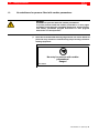
No admittance for persons fitted with cardiac pacemakers
DANGER
WARNING for persons fitted with cardiac pacemakers!
To protect persons fitted with cardiac pacemakers, noentry signs
should be posted because pacemaker malfunction (missed pulses,
total failure), pacemaker program interference or even program
destruction is to be expected!!!
.
Note: We recommend that warning sings like the one shown below are
posted at every entrance to manufacturing shops housing resistancewelding equipment:
No entry for persons with cardiac
pacemakers!
Danger!
DIN 40023
1070 080 087-101 (2001.04) GB
Safety instructions
1.4
1-5
Qualified personnel
The requirements as to qualified personnel are based on the requirements
profiles as defined by the ZVEI (Zentralverband Elektrotechnik und Elektronikindustrie - German Electrical and Electronic Manufacturers’ Association) and the VDMA (Verband deutscher Maschinen- und Anlagebau German Engineering Federation) in:
Weiterbildung in der Automatisierungstechnik
edited by: ZVEI and VDMA
Maschinenbau Verlag
Postfach 71 08 64
D-60498 Frankfurt.
This manual is designed for technicians and engineers with special welding
training and skills. They must have a sound knowledge of the hardware components of the weld timer, the medium-frequency inverters and the welding
transformers.
Interventions in the hardware and software of our products, unless described otherwise in this manual, are reserved to specialized Bosch personnel.
Tampering with the hardware or software, ignoring warning signs attached to
the components, or non-compliance with the warning notes given in this
manual can result in serious bodily injury or property damage.
Only skilled persons as defined in IEV 826-09-01 who are familiar with the
contents of this manual may install and service the products described.
Such personnel are
D those who, being well trained and experienced in their field and familiar
with the relevant standards, are able to analyze the work to be carried out
and recognize any hazards.
D those who have acquired the same amount of expert knowledge through
years of experience that would normally be acquired through formal technical training.
DANGER!
An exception are persons with cardiac pacemakers!
The strong magnetic fields occurring in resistance welding may affect the proper functioning of pacemakers. This may be fatal or cause
serious personal injury!
Therefore, persons with pacemakers must stay clear of resistance
welding systems.
We recommend that warning sings as per DIN 40023 are posted at every entrance to manufacturing shops housing resistance-welding
equipment.
Please note our comprehensive range of training courses. More information
is available from our training center (Phone: +49 / 6062 / 78-258).
1070 080 087-101 (2001.04) GB
1-6
1.5
Safety instructions
Installation and assembly
DANGEROUS ELECTRICAL VOLTAGE
Before the modules are installed, the respective mounting station
must be safely isolated from supply and properly safeguarded to prevent unintentional or unauthorized reclosing.
DANGER
Danger of injury and of damage to property through incorrect installation!
Devices and, in particular, operating means, must be installed so as
to be properly safeguarded against unintentional operation or contact.
DANGER
Danger of personal injury and damage to property through inadequate fastening!
The place for installing the welding transformers, and their method
of fastening, must be suitable for their weight!
Injuries and bruises may be caused by lifting weights which are too
heavy or by sharp metal edges!
Due to the heavy weight of individual modules several persons are
required for installation and assembly.
Wear safety shoes and safety gloves!
DANGER
Non-workmanlike installation or mounting may lead to personal injury or damage to property.
Therefore, it is essential that you take the technical data (environmental conditions) into account for installation or mounting.
Installation or mounting must be carried out by skilled personnel
only.
CAUTION
Leaks in the cooling water circuit may cause consequential damage!
Cooling water leaks may damage adjacent components. Therefore,
when mounting water-cooled modules, always ensure that other devices in the switchgear cabinet are well protected against leaking
cooling water.
1070 080 087-101 (2001.04) GB
Safety instructions
1-7
CAUTION
Damage to property through inappropriate or insufficient cooling of
the welding transformers!
Water-cooled welding transformers may only be operated when the
cooling water circuit is active! Condensation on water-carrying components must be prevented.
Damage to property through insufficient water quality in the cooling
water circuit!
Deposits in the cooling system may reduce the water flow, thus impairing the performance of the cooling system with time.
Therefore, you should ensure that your cooling water has the following properties:
D pH value
: 7 to 8.5
D Degree of hardness Dmax : 10 German degrees
(1 German degree = 1.25 British degrees = 1.05 US degrees =
1.8 French degrees)
D Chlorides
: max. 20 mg/l
D Nitrates
: max. 10 mg/l
D Sulfates
: max. 100 mg/l
D Insoluble substances
: max. 250 mg/l
Tap water usually meets these requirements. However, an algicide
should be added.
L
1070 080 087-101 (2001.04) GB
Make sure that all contact surfaces are bright, i.e. free of paint, plastic coating or dirt/oxidation.
1-8
1.6
Safety instructions
Electrical connection
DANGEROUS ELECTRICAL VOLTAGE
The primary voltage of the welding transformer is associated with
many dangers!
Possible consequences of improper handling include death or most
severe injuries (personal injuries) and damage to property. For this
reason, the electrical connection must always be made by an electrical expert in compliance with the valid safety regulations, the mains
voltage and the maximum current consumption of the individual
units of the equipment.
The mains voltage must match the nominal voltage given on the
nameplate of the product!
DANGEROUS ELECTRICAL VOLTAGE
Working with system voltage may result in death, severe bodily injury or considerable damage to property unless the appropriate precautionary measures are taken.
Therefore, you should carefully read the safety instructions at the beginning of this manual where you will find a description of a number
of features to be strictly observed! The system voltage is associated
with considerable dangers!
Possible consequences of improper handling include death or most
severe injuries (personal injuries) and damage to property. For this
reason, the electrical connection must always be made by an electrical expert in compliance with the valid safety regulations, the mains
voltage and the maximum current consumption of the individual
units of the equipment.
Incorrect mains voltage may render the system dangerous or cause
electrical component failure!
Therefore, please ensure the following:
D The mains voltage must match the nominal voltage given on the
nameplate of the product!
D Mains voltage fluctuation or variation from the nominal voltage
must be within the specified tolerance range (see Technical Data).
D The equipment must be appropriately fused on the mains side!
D The welding transformers must be connected to the protective
earthing (PE) circuit of the system. Please ensure that the
cross-sectional area of cables used for protective conductor
wiring is sufficiently large. The electrical continuity of the
protective earthing circuit must be verified in accordance with EN
60204 Part 1.
D Before carrying out any work on the mains system or welding
system connections it must be ensured that the MF inverter has
been safely isolated from the supply for at least 5 minutes (capacitor discharge time).
D Proper and well insulated tools must be used for handling electric
connections!
1070 080 087-101 (2001.04) GB
Safety instructions
1-9
DANGEROUS ELECTRICAL VOLTAGE
Danger of life through insufficient protective conductor system!
The welding transformers must be connected to the protective
earthing (PE) circuit of the system. Please ensure that the
cross-sectional area of cables used for protective conductor wiring
is sufficiently large. The electrical continuity of the protective
earthing circuit must be verified in accordance with EN 60204 Part 1,
cf. Section 3.1.
DANGEROUS ELECTRICAL VOLTAGE
Protective conductor jumper (MPE)
The protective earth for the negative pole of the PSG 3000 can be interrupted by opening the protective earth conductor jumper at the
PSG 3000. In order to protect the operating personnel against dangerous electrical voltages in the event of a break-down of the transformer primary side to the secondary side, in this case, a suitable
protective measure pursuant to EN 50 063 is to be provided! In addition, the transformer is to be marked accordingly.
DANGEROUS ELECTRICAL VOLTAGE
Insufficient degree of protection may be life-threatening or cause
damage to property!
Depending on the type, the protection class of the welding transformer primary terminal is IP 00 or IP 54.
To prevent accidental contact, the primary terminal must be
equipped with a touch guard.
An additional terminal box of a higher class of protection must be
used for connecting the welding transformers.
DANGEROUS ELECTRICAL VOLTAGE
The electrical connection must always be made by an electrical expert in compliance with the valid safety regulations, the mains voltage and the maximum current consumption of the individual units of
the equipment.
Prior to connecting an MF inverter, the following must be strictly
observed:
D Power OFF.
D Provide a safeguard to prevent unintentional reclosing.
D Verify that the system is safely isolated from supply and
de-energized.
D Connect to earth and short circuit.
D Cover up or safeguard all live parts.
1070 080 087-101 (2001.04) GB
1-10
Safety instructions
CAUTION
Connecting lines and signal lines must be laid so as to avoid negative effects on the function of the units through capacitive or inductive interference!
Interference is frequently coupled and de-coupled in long cables.
Therefore, inverter cables and control cables must be routed separately.
The influence of interfering cables on cables susceptible to interference can be minimized by keeping the following distances:
D > 100 mm if cables are run in parallel for < 10 m,
D > 250 mm if cables are run in parallel for > 10 m.
CAUTION
Connection cables may come off and apply dangerous voltage to
system components!
It is crucial that cables are properly fixed.
L
PE connection
:
Connect to a central earth point. Make sure
that cable cross-sectional areas are
sufficiently large!
L
U connection
:
Connect to U2 on MF inverter.
L
V connection
:
Connect to V2 on MF inverter.
L
Primary side connection :
L
All conductor cross-sections must be large enough for for the loads to be
connected.
For some welding transformers, the degree of
protection of the primary terminal is IP 00.
Additional protection against accidental
contact is required, see Section 6.2.
1070 080 087-101 (2001.04) GB
Safety instructions
1.7
1-11
System perturbation
When operating a welding system a harmonic load must be accounted for in
the mains system. This load is caused by the ”B6 rectifier circuit with a
smoothing capacitor”.
The following figure shows the typical curve of the mains voltage (top) and
the related mains current (bottom) in one phase during the welding process:
Typical 300 Hz
The 5th, 7th, 11th, 13th, 15th, and 17th harmonic wave are the characteristic
harmonics of the mains current curve.
The harmonic component depends on the welding power.
.
1070 080 087-101 (2001.04) GB
The harmonic content may be considerably reduced, e.g., by using
smoothing reactors with 4% short-circuit voltage.
1-12
1.8
Safety instructions
Ensuring EMC of the completely assembled system
.
The completely assembled system complies with prEN 50240, the EMC
product standard for resistance welding systems, and EN 55011
(October 1997), EMC product family standard class A, group 2, rated
current > 100 A.
Only for industrial applications.
Safe clearance from residential areas y 30 m.
Safe clearance to communication systems (wireless, telephone) y 10 m.
Cable length of mains feeder y 10 m.
Interference suppression measures: When switchgear cabinet doors are
open, operation of radio devices or cell phones is permitted only beyond
a safe clearance of y 2 m.
D The assessment and certificate of conformity of a competent authority
concerning compliance with the fundamental EMC protection is available.
D
D
D
D
D
1070 080 087-101 (2001.04) GB
Safety instructions
1.9
1-13
Operation of the welding transformers
DANGER
Danger of personal injury and damage to property through missing
or false interpretation of fault messages!
Therefore, closing of the temperature contact (thermostatic switch,
break contact) of the welding transformer must inhibit the connected
timer!
DANGER
Danger of bruises through electrode movement!
All users, line designers, welding machine manufacturers and welding gun producers are obliged to connect the output signal of the
Bosch weld timer which initiates the electrode movement so that the
applicable safety regulations are complied with.
The risk of bruises can be considerably reduced by means of, e.g.,
two-handed start, guard rails, light barriers etc.
CAUTION
Damage to property through insufficient cooling!
Ensure proper cooling during operation. The maximum permitted
cooling-water temperature must not be exceeded. Condensation on
water-carrying components must be prevented.
CAUTION
Damage to property through excessive welding current!
The maximum welding current depends on the medium-frequency
inverter and the welding transformer in use. It must not be exceeded.
Therefore, the user must check the load in each case.
Any and all warranty excluded in case of non-compliance.
1070 080 087-101 (2001.04) GB
1-14
1.10
Safety instructions
Retrofits and modifications by the user
DANGER
Retrofits or modifications may have negative effects on the safety of
the unit!
Product modification may cause death, severe or light personal
injury, damage to property or environmental damage.
Therefore, please contact us prior to making any modification. This
is the only way to determine whether modified components are
suitable for use with our products.
1070 080 087-101 (2001.04) GB
Safety instructions
1.11
1-15
Maintenance, repair
DANGEROUS ELECTRICAL VOLTAGE
Prior to any maintenance work - unless described otherwise - the
system must always be switched off!
In the event of necessary measurement or test procedures on the active system, these have to be performed by skilled electrical personnel.
In any case, suitable insulated tools must be used!
DANGEROUS ELECTRICAL VOLTAGE
If you need to open the primary connection, disconnect the system
from supply and wait at least 5 minutes after disconnecting the in
verter supply before you open the housing so as to ensure that the
MF inverter is deenergized.
DANGER
Danger of life through inappropriate EMERGENCY-STOP facilities!
EMERGENCY-STOP facilities must be operative and accessible in all
modes of the system. Releasing the EMERGENCY-STOP facility
must by no means result in an uncontrolled restart of the system!
First check the EMERGENCY-STOP circuit, then switch the unit on!
DANGER
The right to perform repair/maintenance work on the weld timer components is reserved to the BOSCH service department or to repair/
maintenance units authorized by BOSCH!
CAUTION
Only use spare parts approved by BOSCH!
1070 080 087-101 (2001.04) GB
1-16
1.12
Safety instructions
Working safely
DANGER
During operation of the welding equipment welding splashes are to
be expected! They may cause eye injuries or burns.
Therefore:
D wear protective goggles
D wear protective gloves
D wear flame-retardant clothes
DANGER
Danger of injury from sheet metal edges and danger of burns from
weld metal!
Therefore: - wear protective gloves
DANGER
In the environment of resistance welding systems, magnetic field
strengths have to be expected which are above the limit values specified in VDE 0848 Part 4. Especially if manual guns are used, the limit
values for extremities may be exceeded.
If in doubt, measure the field strength and take additional measures
to ensure safety and health at work.
CAUTION
The strong magnetic fields occurring in the resistance welding process may cause permanent damage to wrist watches, pocket
watches, or cards with magnetic stripes (e.g. EC cards).
Therefore, you should not carry any such items on you when working
in the immediate vicinity of the welding equipment.
1070 080 087-101 (2001.04) GB
Safety instructions
1.13
1-17
CE conformity
CAUTION
The CE mark is valid for the welding transformer with respect to the
Low-Voltage Directive 72/23 EEC and the standards EN 60204, Part 1
and EN 50063, cf. “Declaration of Conformity”. Concerning EMC, it
is always necessary to consider the entire application.
The CE mark for MF inverter - welding transformer combinations is
valid for industrial applications.
For other combinations/applications, the certificate must be derived
from the above, or a new certificate must be issued, if necessary. This
is a responsibility of the line designer / user.
1070 080 087-101 (2001.04) GB
1-18
Safety instructions
Notes:
1070 080 087-101 (2001.04) GB
Setup
2
Setup
2.1
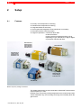
Features
D
D
D
D
D
D
2-1
Primary circuit temperature monitoring
Rectifier block temperature monitoring
Integrated diodes in secondary
Some types with integrated current transformer in secondary
External protective conductor jumper
Degree of protection: transformer block IP65
rectifier block IP00
primary terminal compartment IP00 or IP 54,
depending on type; terminal box of higher degree
of protection required with IP00
PSG 3100.00 A,
similar design:
PSG 3100.00 P
PSG 3100.00 S
PSG 3100.00 C
PSG 3200.00 A
PSG 3050.00 A,
similar design:
PSG 3050.10 A
PSG 3050.10 S
PSG 3075.10 A,
similar design:
PSG 3075.10 P
PSG 3025.00
Medium-frequency welding transformers
The welding transformers must be connected to a Bosch MF inverter with an
output frequency of 1 kHz.
Rectifier block and primary winding temperatures are monitored and their
values transmitted. Any error message occurring must invariably block the
gate control.
1070 080 087-101 (2001.04) GB
2-2
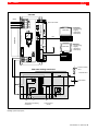
Setup
PSI 6000
Mains
Slot for Q module
U1
A
D
D
R
Heat sink
D - 64711 Erbach 107 Made in Germany
U1 V1 W1
3/PE~
type-specific I/O system
V1
W1
Local PC:
BOS-5000
• programming,
• logging,
• diagnostics,
• fault display
V24
U2 V2 2/~
2/PE
~
-
+
Host PC:
Slot for field bus module
BOS-5000
U2
• programming,
• logging,
• diagnostics,
• fault display
Field bus for progr. (option)
V2
Pressure control
valve
PSG 3000 welding transformer
Solenoid valve
U
150° C
u
Electrodes
MPE
80° C
u
150° C
u
V
T2
T1
Temperature monitoring
connection
M
Current sensor
(toroid)
Welding system layout plan
1070 080 087-101 (2001.04) GB
Setup
2.2
2-3
Function
Medium-frequency welding technology allows efficient energy conversion
using lightweight transformers. Due to the higher operating frequency, both
the iron content and the size of the transformers can be reduced without affecting performance.
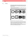
The figure below shows the difference between welding equipment with
1-phase AC and medium-frequency DC.
50 / 60 Hz single-phase alternating current
50 / 60 Hz
Timer
Thyristor
unit
Welding
transformer
Welding
apparatus
1 kHz medium-frequency direct current
50 / 60 Hz
Timer
3~
+
−
MF inverter
Transformerrectifier
Welding
apparatus
Schematic block diagram of 1-phase AC and MF DC welding systems
The 50 / 60 Hz mains AC is first rectified by a bridge rectifier (B6 connection).
The direct current thus generated connects a transistorized H-bridge alternatingly to the welding transformer with a frequency of 1 kHz. The welding
current is rectified in the welding transformer secondary.
Welding current amperage is controlled by adjusting the pulse width. The
welding current is measured by a current sensor incorporated in the secondary circuit of the PSG 3000 welding transformer.
1070 080 087-101 (2001.04) GB
2-4
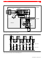
Setup
PSI 6000
Direct current link circuit
6-pulse bridge
rectifier
mains
L1
U1
L2
V1
L3
W1
power
supply
Transistor inverter
controller
driver
U2
V2
U
V
PSG 3000
Welding transformer
terminal box
Weld timer
PSG sensors
Rectifier
Block diagram of a medium-frequency inverter system
Primary voltage
UPRIM
[1]
t
[2]
Primary voltage
setting range
f = 1 kHz
Secondary current
[2] high current
ISEC
Imean value
[1] low current
t
Primary voltage and secondary current in an MF welding system
1070 080 087-101 (2001.04) GB
Protective conductor connection
3
3-1
Protective conductor connection
The BOSCH PSG 3000 MF transformers comply with protection class 1 in
accordance with DIN VDE 0551 Part 1.
Additional protective measures as per EN 50063 (DIN VDE 0545, Part 1)
must be taken for protection class 1 devices to provide protection against
inadmissibly high touch voltage in case of an insulation breakdown between
primary and secondary circuits. The implementation of these measures is
the responsibility of the machine/system manufacturer/operator.
DANGEROUS ELECTRICAL VOLTAGE
If these protective measures are not applied, or if they are ineffective,
touching the secondary connections, the welding gun or the workpiece is associated with danger of life and limb!
Welding transformers are delivered with a detachable protective conductor
jumper (MPE) connected between the MF transformer secondary (negative
pole) and the protective conductor terminal. This is in compliance with the
protective measure of a ”direct protective conductor connection” as per Section 5.1.4.1, EN 50063.
If another protective measure to EN 50063 is implemented instead of a
”direct protective conductor connection”, the protective conductor jumper
(MPE) must be removed.
The removal of the protective conductor jumper (MPE) must be indicated on
the label provided on the transformer in a permanent way.
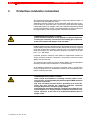
As an additional measure for devices of protection class 1, the MF transformer housings have non-detachable connections to the transformer protective conductor terminals.
DANGEROUS ELECTRICAL VOLTAGE
Under certain circumstances, circulating currents (called ”crossover currents” as per EN 50063) may flow through the MPE protective
conductor connection.
Any such circulating currents must be prevented at all events because they may interrupt the protective conductor continuity
through the protective conductor jumper (MPE).
Interrupting the protective conductor connection will render the protective measure of a ”direct protective conductor connection” ineffective. Therefore, in the case of an insulation breakdown there is
danger of life!
1070 080 087-101 (2001.04) GB
3-2
3.1
Protective conductor connection
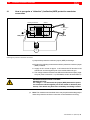
How to recognize a ”defective” (ineffective) MPE protective conductor
connection
welding transformer
rectifier
+
electrode gun
U
V
PE
MPE
-
open
test point
test point
housing
max. 1 V
I approx.
10 A
AC
Checking the protective conductor connection
1.) Inspect the protective conductor jumper (MPE) for damage.
2.) Perform the following measurement with the protective conductor jumper
(MPE) installed!
D Supply an AC current of approx. 10 A between the PE terminal of the
transformer and the negative pole of the rectifier/electrode gun.
D The voltage measured between the PE terminal and the test point (negative pole) must not exceed 1 V (cf. EN 60204, Section 20.2 and Table 7).
DANGEROUS ELECTRICAL VOLTAGE
DANGER OF LIFE!
If a voltage > 1 V is measured, the jumper (MPE) between the protective conductor and the negative pole of the rectifier is defective (ineffective). This defect may have been caused by circulating currents.
.
Note: The measurement described above may be performed analogously to
check the protective conductor connection to the transformer housing.
1070 080 087-101 (2001.04) GB
Protective conductor connection
3.1.1
3-3
What are circulating currents?
Circulating currents are defined as currents which do not flow as desired
from the positive pole of the welding equipment through the workpiece and to
the negative pole of the welding equipment during the welding process, but
rather through the workpiece and then through external ”ground connections” and the protective conductor jumper (MPE) to the negative pole.
3.1.2
When do circulating currents occur?
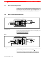
Case 1
welding transformer
rectifier
+
U
V
PE
supply line
(
(
MPE
-
(
workpiece
housing
No circulating currents
Negative pole grounded through protective conductor jumper (MPE), workpiece not grounded (ideal arrangement).
No circulating currents can occur.
Case 2
welding transformer
rectifier
+
workpiece
U
V
PE
supply line
(
(
MPE
-
(
housing
Circulating currents occur
Negative pole grounded via protective conductor jumper (MPE), workpiece
grounded, welding transformer housing insulated from
.
There will be circulating currents through the mains supply line.
1070 080 087-101 (2001.04) GB
Protective conductor connection
3-4
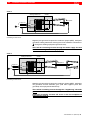
Case 3
welding transformer
rectifier
+
workpiece
U
V
PE
supply line
(
(
-
MPE
(
housing
Circulating currents occur
Negative pole grounded via protective conductor jumper (MPE), workpiece
grounded, welding transformer housing has a low-resistance connection to
through the welding equipment (practical case).
There will be circulating currents through the mains supply line and
furthermore through the welding equipment.
Case 4
welding transformer
rectifier
+
supply line
U
V
PE
workpiece
(
(
MPE
-
(
MPE
housing
Circulating currents occur
Negative pole grounded via protective conductor jumper (MPE), workpiece
not grounded, several electrode guns (with their negative poles also
grounded) are employed simultaneously.
There will be circulating currents through the ”neighboring” electrode
guns.
Additional circulating currents will occur if also the workpiece is
grounded (cf. Case 3).
1070 080 087-101 (2001.04) GB
Protective conductor connection
3.1.3
3-5
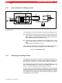
How to measure circulating currents
welding transformer
rectifier
+
supply line
U
V
PE
(
(
MPE
-
(
[1]
+
[2]
workpiece
A
housing
max. 1 V
welding current
meter
Circulating currents
A DC welding current meter is required for measuring circulating currents.
[1]
Apply belted measuring cable to the positive pole of the weld gun and
fix it in position. Close the weld gun without a workpiece being used,
apply welding current (with MF inverter in closed-loop current control
mode). Measure and record welding current I[1].
[2]
Close the weld gun on a workpiece, close ”neighboring gun”, if any,
(Case 4), apply welding current with current conditions as under [1]
above.
Measure and record welding current I[2].
If the current values are different, the presence of circulating currents has to
be assumed. The amount of the circulating current is calculated as
I[2] - I[1] ~ circulating current.
3.1.4
Remedying circulating currents
If circulating currents cannot be avoided by the protective measure of a ”direct protective conductor connection”, other protective measures to
EN 50063 must be installed by the machine/plant manufacturer/operator.
For example, protective measures such as current-operated e.l.c.b. systems or voltage-operated e.l.c.b. systems (cf. EN 50063, Sections 5.1.4.3
and 5.1.4.4) may be installed for medium-frequency systems.
However, please read the manufacturer’s specifications carefully and check
whether devices to be used for the measures described above are suitable
for MF system operation with a DC link circuit and at a frequency of 1000 Hz.
The manufacturer’s specifications must be verified accordingly. The applicable standards are to be observed.
1070 080 087-101 (2001.04) GB
Residual-current protective resistor
DANGEROUS ELECTRICAL VOLTAGE
A residual-current protective resistor may be used only as prescribed in
combination with a residual-current protective device with a rated residual
current of x 30 mA (as per EN 60947-2) in TN or TT systems of up to 690 V
for installation on a welding transformer (cf. EN 50063).
No warranty: Supplier excludes any and all liability for any other than the
permitted use, including, without being limited to any use in combination
with any residual current protective device unfit for the intended purpose.
Visual and electrical inspections must be conducted periodically on residual-current protective resistors installed.
Recommended inspection intervals: no more than 6 months.
CAUTION
In order to comply with EN 50063, MF welding systems equipped with residual-current protective devices (for personnel protection) require a residual-current protective resistor to be installed on the welding transformer
with the protective conductor jumper (MPE jumper) removed (cf. Section 5.1.4.3, EN 50063).
:
:
Degree of protection :
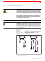
Dimensions
:
1 kΩ "10%
tuned to use in combination with residual-current
protective device, see above
electrical connections IP00, resistor IP65
see diagram
26.4
26.4
BOSCH R1K0 / 4W
BOSCH R1K0 / 4W
∅ 6.5
1070 083 996-101
120.0
158.0
1070 081 822-101
18.2
Technical data
Resistance
Pulse power
18.2
3.2
Protective conductor connection
83.0
3-6
∅ 6.5
∅ 6.5
∅ 6.5
Residual-current protective resistor
1070 080 087-101 (2001.04) GB
Protective conductor connection
line switch
U
V
W
current trans
former
residualcurrent protective resistor
transformer
MF inverter
(
(
(
undervoltage re
lease
PE
rectifier
3-7
+
-
workpiece
housing
e.l.c.b.
zone of protection
currentoperated e.l.c.b. system
Current-operated e.l.c.b. system to Section 5.1.4.3, EN 50063
The zone of protection against indirect contact includes all components
installed after the current transformer. Indirect contact with live parts will release the line switch.
However, please read the manufacturer’s specifications carefully and check
whether the current-operated e.l.c.b. system to be used for are suitable for
MF system operation with a DC link circuit and at a frequency of 1000 Hz
(cf. EN 50178, EN 60947-2, etc.). The applicable standards are to be observed.
1070 080 087-101 (2001.04) GB
3-8
3.2.1
Protective conductor connection
Installation of a residual-current protective resistor
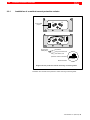
remove MPE
jumper
fixing parts of
MPE jumper
V
U
V
U
bolt, M6x10
spring lock washer, ∅6
plain washer, ∅6
protective resistor connection
MPE connection
Diagram shows protective resistor with long connecting leads.
Installation of a residual-current protective resistor with long connecting leads.
1070 080 087-101 (2001.04) GB
Protective conductor connection
3-9
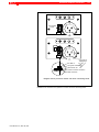
remove MPE
jumper
V
U
V
U
MPE
MPE
fixing parts of
MPE jumper
bolt, M6x10
spring lock washer, ∅6
plain washer, ∅6
protective resistor connection
MPE connection
Diagram shows protective resistor with short connecting leads.
Installation of a residual-current protective resistor with short connecting leads.
1070 080 087-101 (2001.04) GB
3-10
3.3
Protective conductor connection
Ordering protective resistors
Designation
Part No.
Protective resistor (short connecting leads)
1070 081 822
Protective resistor (long connecting leads)
1070 083 996
1070 080 087-101 (2001.04) GB
Connection
4
Connection
4.1
PSG 3XXX.XX X to inverter
to electrodes
−
+
not available with all
transformer types
white
brown
current sensor
black
to inverter
yellow
3 thermostatic
switches connected in series
screened cable for
inverter
connection, not
included in the
delivery!
PSG 3XXX
MPE
U
V
to power output of
inverter
type of attachment
depends on
transformer type
PSG 3XXX.XX X connection to inverter
1070 080 087-101 (2001.04) GB
4-1
4-2
Connection
4.2
Parallel connection of PSG 3XXX.XX X
D two PSG 3100.XX X connected to PSI 6200.XXX
D two PSG 3200.XX X connected to PSI 6500.XXX
D four PSG 3100.XX X connected to PSI 6500.XXX
(connected accordingly as shown for 2 transformers in the diagram below)
screened cable for
inverter
connection, not
included in the
delivery!
not available with all
transformer types
white
current sensor
brown
black
to inverter
yellow
3 thermostatic
switches connected in series
screened cable for
inverter
connection, not
included in the
delivery!
PSG 3XXX
MPE
U
V
to power output
of inverter
not available with all
transformer types
white
brown
current sensor
black
yellow
3 thermostatic
switches connected in series
PSG 3XXX
MPE
U
V
PSG 3XXX.XX X parallel connection to inverters
1070 080 087-101 (2001.04) GB
Maintenance
5
5-1
Maintenance
DANGEROUS ELECTRICAL VOLTAGE
Maintenance work must always be carried out by an electrical expert
in compliance with the valid safety regulations, the mains voltage
and the maximum current consumption of the individual units of the
equipment.
Prior to connecting an MF inverter, the following must be strictly
observed:
- Power OFF.
- Provide a safeguard to prevent unintentional reclosing.
- Verify that the system is safely isolated from supply and
de-energized.
- Connect to earth and short circuit.
- Cover up or safeguard all live parts.
DANGEROUS ELECTRICAL VOLTAGE
Prior to any maintenance work - unless described otherwise - the
system must always be switched off!
If the system was active shortly before, wait until the system is totally
de-energized before starting the maintenance work (e.g. because of
charged capacitors, etc.). The system must always be safeguarded
against unintentional reclosing while maintenance work is performed!
In the event of necessary measurement or test procedures at the active system, the applicable safety and accident prevention regulations must be strictly observed. In any case, suitable insulated tools
must be used!
If you need to open the MF inverter housing, disconnect the system
from supply and wait at least 5 minutes before you open the housing
so as to ensure that the MF inverter is de-energized.
Danger of life through inappropriate EMERGENCY-STOP facilities!
EMERGENCY-STOP facilities must be operative in all modes of the
system. Releasing the EMERGENCY-STOP facility must by no means
result in an uncontrolled restart of the system!
DANGEROUS ELECTRICAL VOLTAGE
The right to perform repair/maintenance work on the components is
reserved to the BOSCH service department or to repair/maintenance
units authorized by BOSCH!
Only use spare parts/replacement parts approved by BOSCH!
1070 080 087-101 (2001.04) GB
5-2
Maintenance
D Check the cooling water circuit for leaks at regular intervals.
D Add an algicide to the cooling water.
D Check connections and terminals of all connecting cables for tight fit at
regular intervals. Check all cables for damage.
DANGEROUS ELECTRICAL VOLTAGE
Check whether the current-operated e.l.c.b. system / the residualcurrent protective resistor is in proper service condition at least
every 6 months.
1070 080 087-101 (2001.04) GB
Accessories
6
Accessories
6.1
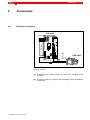
Electrical connection
6-1
PSI 6000
Mains
type-specific I/0 interface
D - 64711 Erbach 107 Made in Germany
A
D
D
R
U2
V2
−
+
slot for fieldbus module
Heat sink
U1
V1
W1
[2]
PSG 3000
[1]
Electrical connection
1070 080 087-101 (2001.04) GB
[1]
screened sensor cable LiYCY2 x 2 x 0,75 mm2, available as an
accessory
[2]
terminal box, flange connectors and connecting sockets available as
accessories
Accessories
6-2
6.2
Primary connection of welding transformer
There are two options for the primary connection of the MF welding transformer:
D Provide terminals V, U and the ground terminal with cable clamps and
screw them onto the respective contact pieces. A suitable transformer
terminal box is the TH 3000 terminal box with cable-gland Pg connection
(heavy-gauge screwed conduit connection), see diagram below.
D Welding transformers are delivered with three plug contacts, ea., which
can be screwed into the contact tubes. They provide plug-in connection
for the welding transformer primary.
For information on the matching female connectors and suitable transformer terminal boxes, please see the following descriptions.
6.2.1
Terminal box TH 3000/Pg
Suitable for all PSG 3000 transformer types (except for PSG 3025.00 A and
PSG 3XXX.XX P variants) with primary connection through cable-gland Pg
connection.
55
1
52
106
5,5
1
63
right-hand and left-hand
knock-out panel for Pg29
and MC flanged socket
150
50
118
12
Terminal box TH 3000/PG
1070 080 087-101 (2001.04) GB
Accessories
6.2.2
6-3
Terminal box TH 3050/MC
Suitable for PSG 3050.XX X or PSG 3075.XX X (except for PSG 3XXX.XX P
variants) for MC 135 multi-contact connection.
55
1
5
52
106
5,5
1
63
right-hand and left-hand
knock-out panel for Pg29
and MC flanged socket
135A
150
50
118
12
Terminal box TH 3050/MC
Flange connector suitable for PSG 3050.XX X or PSG 3075.XX X for MC 135
multi-contact connection (contact pins) on welding transformer.
welding
transformer
terminal box
flange connector,
individual parts
socket holder
screwed-on contact
pins
sockets
mounting flange
V
U
right-angle
shrink-on sleeve
Flange connector
1070 080 087-101 (2001.04) GB
straight shrink-on
sleeve
6-4
Accessories
6.2.3
Terminal box TH 3100/MC
Suitable for PSG 3100.00 X (except for PSG 3XXX.XX P variants) for
MC 180 multi-contact connection.
55
1
5
52
106
5,5
1
63
right-hand and left-hand
knock-out panel for Pg29
and MC flanged socket
180A
150
50
118
12
Terminal box TH 3100/MC
Flange connector suitable for PSG 3100.00 X for MC 180 multi-contact connection (contact pins) on welding transformer.
welding
transformer
terminal box
flange connector,
individual parts
socket holder
screwed-on
contact pins
sockets
U
b
mounting flange
V
a
right-angle
shrink-on sleeve
straight
shrink-on sleeve
Flange connector
1070 080 087-101 (2001.04) GB
Accessories
6.3
6-5
Ordering PSG accessories
Not included in the delivery of MF welding transformers:
Designation
Part no.
Terminal box TH 3000/PG suitable for all PSG 3000 welding
transformers (except for PSG 3025.00 A and PSG 3XXX.XX
P variants)
1070 917 826
Terminal box TH 3050/MC
suitable for PSG 3050.XX X or PSG 3075.XX X
for multi-contact connection MC 135/25
(except for PSG 3XXX.XX P variants)
1070 917 828
Flange connector MC 135/25 for multi-contact connection on
PSG 3000, suitable for PSG 3050.XX X
or PSG 3075.XX X
Terminal box TH 3100/MC
suitable for PSG 3100 for multi-contact connection
MC 180/50 (except for PSG 3XXX.XX P variants)
Flange connector MC 180/50 for multi-contact connection on
PSG 3000, suitable for PSG 3100
Cable for PSG sensors 2 x 2 x 0,75 mm2, screened LiYCY
1070 080 087-101 (2001.04) GB
on request
1070 917 827
on request
1070 913 494
6-6
Accessories
Notes:
1070 080 087-101 (2001.04) GB
Load diagrams
7
7-1
Load diagrams
DANGER
Danger of damage to property through inadmissibly high welding
current!
Therefore, read the load diagrams to see whether the maximum welding current of your application is within the permitted range.
The modules should only be operated with appropriate cooling!
The load diagrams define the maximum admissible welding current of the
PSG unit depending on the duty cycle (ED).
The maximum admissible welding current depends not only on the duty cycle of the rectifier diodes, but also on the duty cycle of the PSG 3000 (transformer) used.
All load diagrams are based on the thermal transient recovery times (integration time) of the rectifier diodes (2 seconds) and the transformers (60 seconds). These data together with some application-specific data (number of
spot welds per minute; number of weld time periods, number of overall weld
cycles) are used to determine
D 1. the maximum admissible welding current depending on the diode
load and
D 2. the maximum admissible welding current depending on the transformer load.
To ensure proper execution of weld schedules, the lowermost of these
two values must not be exceeded!
1070 080 087-101 (2001.04) GB
7-2
Load diagrams
7.1
Rating example
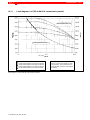
D 1. Look for the related load diagram of the PSG 3000 you want to use.
Example:
i1ipo: 22.2
i1: 21.2
20,00
P1ipo
P1
P2
Isec [kA]
i2: 17.1
diode integration time: 2 s
PSG integration time: 60s
10,5
20.0
Transformer- (and inverter-) related limitation
Diode-related limitation at 50 weld time periods
Diode-related limitation at 20 weld time periods
Diode-related limitation at 10 weld time periods
Diode-related limitation at 5 weld time periods
ED (duty cycle) [%]
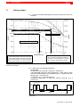
30.0
The load curves represent absolute limit values. To ensure the reliability in continuous
operation, we recommend that no more than
80% of the max. load capacity be utilized.
Example of load diagram
D 2. Write down your welding parameters.
Sample data:
20 sequences per minute (’ 1 sequence = 60s/20=3s).
150 overall weld cycles (incl. all non-weld times, i.e. SQZ, OFF, CT, WLD,
HOLD and all idle times) ’ 150 overall weld cycles = 1 sequence ’ 1 overall weld cycle = 3s/150=0.02s.
1st sequence: 2 x 15 weld time periods:
subsequent sequences: 15 weld time periods, each (’ ts=15 x
0.02s=0.3s)
15 cycles, each
Isec
3 sec
3 sec
60 sec
Sample data
1070 080 087-101 (2001.04) GB
Load diagrams
7-3
D 3. Calculate the duty cycle (ED) [2s] of the diodes on the basis of the sequence with the highest number of weld time periods:
ED [2s] =
number of weld time periods
30 periods x 0.02
x 100 % =
x 100 % = 30 %
2 seconds
2 seconds
D 4. Use the load diagram to determine the maximum welding current permitted for the diodes.
First, draw a vertical line through the duty cycle value of the diodes which
you have just calculated (ED=30%).
Next, take the characteristic of the diodes with the next higher number of
weld time periods than the required one (with 30 weld time periods given
in the example, this would be the characteristic) and mark its intersection with the vertical line you have drawn.
Now, you can find the max. welding current i1 permitted for the diodes at
the level of intersection P1 on the left axis (approx. 21 kA in this example).
Optionally, you can determine the point of intersection by interpolation
between two characteristics, taking the actual number of weld time periods as a basis of calculation (characteristics and V in this example;
see intersection P1ipo). This way you can determine the max. welding
current in our example more precisely at approx. 22.2 kA (i1ipo).
D 5. Calculate the duty cycle ED[60s] of the PSG 3000:
0.3s x 21
t x number of spots per min. + 1
x 100 % =
x 100 % = 10.5 %
ED [60s] = s
60 s
60s
(Note : For the calculation of ts, see step 2 above)
D 6. Use the load diagram to determine the max. welding current permitted
for the PSG 3000 transformer.
First, draw a vertical line through the duty cycle value of the PSG transformer which you have calculated previously (ED = 10.5%).
Next, mark the intersection of the Y characteristic with the vertical line.
Now, you can find the max. welding current i2 permitted for the PSG 3000
transformer at the level of intersection P2 on the left axis (approx. 17 kA in
this example).
D 7. The maximum welding current for any welding operation should always be defined by the lower of the two welding currents i1 and i2 thus
determined (17 kA in this example).
1070 080 087-101 (2001.04) GB
7-4
Load diagrams
Notes:
1070 080 087-101 (2001.04) GB
Type overview
8
Type overview
PSG 3025.00 A
D Medium-frequency welding transformer, 12 kVA
D Welding current range: 0.25 to 6 kA
D Integrated temperature monitoring
PSG 3050.00 A
D Medium-frequency welding transformer, 56 kVA
D Welding current range: 3 to 20 kA
D Integrated current sensor and temperature monitoring
PSG 3050.10 A
D Medium-frequency welding transformer, 56 kVA
D Welding current range: 3 to 20 kA
D Integrated current sensor and temperature monitoring
D Higher diode rating than PSG 3050.00 A
PSG 3050.10 S
D Medium-frequency welding transformer, 56 kVA
D Welding current range: 3 to 20 kA
D Integrated current sensor and temperature monitoring
D Connection for secondary voltage monitoring
D Higher diode rating than PSG 3050.00 A
PSG 3075.10 A
D Medium-frequency welding transformer, 75 kVA
D Welding current range: 3 to 20 kA
D Integrated current sensor and temperature monitoring
D Higher diode rating than PSG 3075.00 A
PSG 3075.10 P
D Medium-frequency welding transformer, 75 kVA
D Welding current range: 3 to 20 kA
D Integrated temperature monitoring
D For primary current regulation, without current sensor
D Higher diode rating than PSG 3075.00 A
1070 080 087-101 (2001.04) GB
8-1
8-2
Type overview
PSG 3100.00 A
D Medium-frequency welding transformer, 100 kVA
D Welding current range: 3 to 36 kA
D Integrated current sensor and temperature monitoring
PSG 3100.00 P
D Medium-frequency welding transformer, 100 kVA
D Welding current range: 3 to 36 kA
D Integrated temperature monitoring
D For primary current regulation, without current sensor
PSG 3100.00 S
D Medium-frequency welding transformer, 100 kVA
D Welding current range: 3 to 36 kA
D Integrated temperature monitoring
D Integrated current sensor and temperature monitoring
D Connection for secondary voltage monitoring
PSG 3100.00 C
D Medium-frequency welding transformer, 100 kVA
D Welding current range: 3 to 36 kA
D Integrated current sensor and temperature monitoring
D For multi-contact connector MC 135
PSG 3200.00 A
D Medium-frequency welding transformer, 200 kVA
D Welding current range: 6 to 40 kA
D Integrated current sensor and temperature monitoring
1070 080 087-101 (2001.04) GB
PSG 3025.00 A
9
PSG 3025.00 A
9.1
Technical data, PSG 3025.00 A
1070 080 087-101 (2001.04) GB
9-1
Medium-frequency transformer-rectifier
unit SN
12 kVA; at X = 50%
Primary voltage U1N
500 V
Max. primary continuous current I1P
14 A
Secondary current range I2N
0.25 to 6 kA
Rated direct current Id
1.4 kA 50% duty cycle (ED); level 1
Continuous direct current Id
1.0 kA 100% duty cycle (ED); level 1
Cable cross-section U2/V2 -> U/V
y4mm2
Frequency f
1000 Hz
Transformer ratio Ü
144 : 1;
72 : 1;
No-load direct voltage UdiO
2.8 V; level 1
6.2 V; level 2
level 1
level 2
Continuous d.c. forward current
rating PdiO
6.2 kW 100% duty cycle (ED); level 1
Max. direct current Id max.
cf. load diagram
Transformer degree of protection
IP65
Primary connection zone degree of
protection
IP54
Welding transformer insulation class
F
Weight
9.3 kg
Color
RAL 5015; blue
Cooling water volume
min. 1 l / min
Cooling water temperature
max. 30° C
Cooling water pressure drop
max. 0.6 bar
Primary circuit monitoring
max. 140° C
Rectifier block monitoring
max. 80° C
9-2
9.2
PSG 3025.00 A
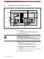
Dimensioned drawing, PSG 3025.00 A
Earthing sign
Nameplate
Cooling water connection
thread M12x1
protective neu
tral conductor
ground con
ductor, housing
4 x M8 − 10 deep on all sides
bolted PG11 connection
(supply) and bolted PG9
connection (temperature
monitoring) supplied for
assembly
View X w/o cover
view of level 2 with pro
tective neutral conduc
tor
Dimensions without tolerances are subject to ”mean” deviations to DIN 7168
Dimensioned drawing, PSG 3025.00 A
9.3
Cooling water connection, PSG 3025.00 A
Maximum supply water temperature: 30° C
WE = water inlet, WA = water outlet
Water connection: hose with 6.3 mm internal diameter,
Type: Parker Push-lock 831-4 WP2.4
1070 080 087-101 (2001.04) GB
PSG 3025.00 A
9.4
9-3
Block diagram, PSG 3025.00 A
MPE [4]
[1] V
4
[5]
Jumper 2
2
Jumper 1 [2]
3
Jumper 2
80° C
u
140° C
u
1
[1] U
a
b
T
[3]
Block diagram, PSG 3025.00 A
[1]
Primary side:
D U welding transformer → U2 medium-frequency inverter
D V welding transformer → V2 medium-frequency inverter
[2]
Jumpers on primary side:
D Optional connection, jumper 1:
Primary winding connected in parallel,
2.8 V no-load output voltage
D Optional connection, jumper 2
Primary winding connected in series
6.2 V no-load output voltage
[3]
Primary winding and rectifier block temperature monitoring T:
Connecting cable 2 x 2 x 0,75 mm2, screened LiYCY.
[4]
MPE neutral earth conductor:
DANGEROUS ELECTRICAL VOLTAGE
If the MPE protective conductor jumper is to be removed, another
protective measure to EN 50063 must be installed.
In this case, the ground connection between the transformer neutral
and the earthing bolt must be crossed out in an indelible manner.
[5]
1070 080 087-101 (2001.04) GB
Secondary side, connection of electrodes
9-4
9.5
PSG 3025.00 A
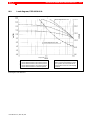
Load diagram, PSG 3025.00 A
6000
5000
Isec [kA]
4000
ts=20ms
ts=40ms
ts=60ms
ts=100ms
ts=200ms
transformer integration time
T=60 s
ts=400ms
ts=600ms
ts=1s
3000
ts=2s
diode integration time: T=2 s
2000
1000
M2 rectifier circuit
2 x 1 diode
80 K temperature gradient
0
10
100
duty cycle (ED) [%]
Limitation by transformer
Load diagram, PSG 3025.00 A
1070 080 087-101 (2001.04) GB
PSG 3025.00 A
9.6
Ordering, PSG 3025.00 A
1070 080 087-101 (2001.04) GB
Designation
Part no.
PSG 3025.00 A welding transformer
1070 079 345
9-5
9-6
PSG 3025.00 A
Notes:
1070 080 087-101 (2001.04) GB
PSG 3050.00 A/PSG 3050.10 A/PSG 3050.10 S
10
PSG 3050.00 A/PSG 3050.10 A/PSG 3050.10 S
10.1
Technical data, PSG 3050.00 A
D with current transformer in secondary circuit
1070 080 087-101 (2001.04) GB
Medium-frequency transformer-rectifier
unit SN
56 kVA; at X = 50%
Primary voltage U1N
500 V
Max. primary continuous current I1P
60 A
Secondary current range I2N
3.0 to 20 kA
Continuous direct current Id
4.2 kA 100% duty cycle (ED)
Cable cross-section U2/V2 -> U/V
y16mm2
Frequency f
1000 Hz
Transformer ratio Ü
70 : 1
No-load direct voltage UdiO
6.3 V
Continuous d.c. forward current
rating PdiO
26.2 kW 100% duty cycle (ED)
Max. rated surge forward current IFSM
50 kA; (10 ms; Tvj max.180° C)
Max. direct current Id max.
cf. load diagram
Transformer degree of protection
IP65
Primary connection zone degree of
protection
IP00
Welding transformer insulation class
F
Weight
14.5 kg
Color
RAL 5015; blue
Cooling water volume
min. 6 l / min
Cooling water temperature
max. 30° C
Cooling water pressure drop
max. 0.6 bar
Primary circuit monitoring
max. 150° C
Rectifier block monitoring
max. 80° C
10-1
10-2
10.2
PSG 3050.00 A/PSG 3050.10 A/PSG 3050.10 S
Technical data, PSG 3050.10 A
D with current transformer in secondary circuit
D with higher diode rating
Medium-frequency transformer-rectifier
unit SN
56 kVA; at X = 50%
Primary voltage U1N
500 V
Max. primary continuous current I1P
60 A
Secondary current range I2N
3.0 to 20 kA
Continuous direct current Id
4.2 kA 100% duty cycle (ED)
Cable cross-section U2/V2 -> U/V
y16mm2
Frequency f
1000 Hz
Transformer ratio Ü
70 : 1
No-load direct voltage UdiO
6.3 V
Continuous d.c. forward current
rating PdiO
26.2 kW 100% duty cycle (ED)
Max. rated surge forward current IFSM
50 kA; (10 ms; Tvj max.180° C)
Max. direct current Id max.
cf. load diagram
Transformer degree of protection
IP65
Primary connection zone degree of
protection
IP00
Welding transformer insulation class
F
Weight
14.5 kg
Color
RAL 5015; blue
Cooling water volume
min. 6 l / min
Cooling water temperature
max. 30° C
Cooling water pressure drop
max. 0.6 bar
Primary circuit monitoring
max. 150° C
Rectifier block monitoring
max. 80° C
1070 080 087-101 (2001.04) GB
PSG 3050.00 A/PSG 3050.10 A/PSG 3050.10 S
10.3
Technical data, PSG 3050.10 S
D with current transformer in secondary circuit
D with higher diode rating
D with connection for secondary voltage monitoring
Medium-frequency transformer-rectifier
unit SN
56 kVA; at X = 50%
Primary voltage U1N
500 V
Max. primary continuous current I1P
60 A
Secondary current range I2N
3.0 to 20 kA
Continuous direct current Id
4.2 kA 100% duty cycle (ED)
Cable cross-section U2/V2 -> U/V
y16mm2
Frequency f
1000 Hz
Transformer ratio Ü
70 : 1
No-load direct voltage UdiO
1070 080 087-101 (2001.04) GB
6.3 V
Continuous d.c. forward current
rating PdiO
26.2 kW 100% duty cycle (ED)
Max. rated surge forward current IFSM
50 kA; (10 ms; Tvj max.180° C)
Max. direct current Id max.
cf. load diagram
Transformer degree of protection
IP65
Primary connection zone degree of
protection
IP54
Secondary connection zone degree of
protection
IP00
Welding transformer insulation class
F
Weight
14.5 kg
Color
RAL 5015; blue
Cooling water volume
min. 6 l / min
Cooling water temperature
max. 30° C
Cooling water pressure drop
max. 0.6 bar
Primary circuit monitoring
max. 150° C
Rectifier block monitoring
max. 80° C
10-3
10-4
PSG 3050.00 A/PSG 3050.10 A/PSG 3050.10 S
10.4
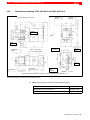
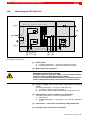
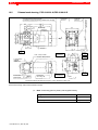
Dimensioned drawing, PSG 3050.00 A and PSG 3050.10 A
Cooling water
outlet G 1/4"
Cooling water
inlet G 1/4"
Touch guard required for primary connection!
Nameplate
rectifier
M8 (6x)
12 deep
4 x M8 − 10 deep on all sides
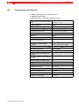
Connection T
Thermal release
M 5 (4 x)
10 deep
2 x ∅ 6H7 − 8 deep on all sides
Earthing
sign
Thermal release
Rectifier
M 6 (5 x)
8 deep
Contact surface
Connection lines
150 mm long (for T, S and
M)
Connection M
Current
transformer
View
Dimensions without tolerances are subject to ”mean” deviations to DIN 7168
Dimensioned drawing, PSG 3050.00 A and PSG 3050.10 A
.
Note: Connecting pins for primary side supplied loosely.
Designation
4 straight pins ISO 8735 ∅ 06 x 12
supplied loosely
3 contact pins MC135 ∅ 06
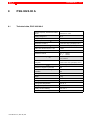
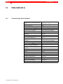
supplied loosely
1070 080 087-101 (2001.04) GB
PSG 3050.00 A/PSG 3050.10 A/PSG 3050.10 S
10.5
10-5
Dimensioned drawing, PSG 3050.10 S
Touch guard required for primary connection!
For connection, cover type and order data, cf. attached sheet no. SKT 0058
Cooling water
inlet G 1/4"
Cooling water
outlet G 1/4"
Nameplate
rectifier
M8 (6x)
12 deep
4 x M8 − 10 deep on all sides
2 x ∅ 6H7 − 8 deep on all sides
Connection T
Thermal
release
M 5 (4 x)
10 deep
Earthing
sign
Connection S
Sec. circuit
monitoring
Contact surface
Contact surface
Contact surface
Connection M
Current
transformer
Connection lines
150 mm long (for T, S and M)
M 6 (3 x)
8 deep
View
Technical alterations reserved
Dimensions without tolerances are subject to ”mean” deviations to DIN 7168
Dimensioned drawing, PSG 3050.10 S
.
Note: Connecting pins for primary side supplied loosely.
Designation
1070 080 087-101 (2001.04) GB
4 straight pins ISO 8735 ∅ 06 x 12
supplied loosely
3 contact pins MC135 ∅ 06
supplied loosely
10.6
PSG 3050.00 A/PSG 3050.10 A/PSG 3050.10 S
Cooling water connection, PSG 3050.XX X
Maximum supply water temperature: 30° C
WE = water inlet, WA = water outlet
Water connection: internal thread G 1/4” (for example, see sketch)
by the customer
Hose
internal ø 6.3
washer
G 1/4
G1/4
10-6
Double screw neck
DIN EN 560-G 1/4 / G 3/8 RH
Hose nozzle
DIN EN 5606.3
Rear part G 3/8
Union nut
DIN EN 560-G 3/8
Cooling water connection, PSG 3050.00 A/PSG 3050.10 A/PSG 3050.10 S
1070 080 087-101 (2001.04) GB
PSG 3050.00 A/PSG 3050.10 A/PSG 3050.10 S
10.7
10-7
Block diagram, PSG 3050.00 A and PSG 3050.10 A
[1] V
150° C
u
[5]
[2] MPE
80° C
u
150° C
u
[1] U
T2
[3]
Terminating
connector,
external
T1
[3]
M
[4]
Block diagram, PSG 3050.00 A and PSG 3050.10 A
[1]
Primary side:
D U welding transformer → U2 medium-frequency inverter
D V welding transformer → V2 medium-frequency inverter
[2]
MPE neutral earth conductor:
DANGEROUS ELECTRICAL VOLTAGE
If the MPE protective conductor jumper is to be removed, another
protective measure to EN 50063 must be installed.
In this case, the ground connection between the transformer neutral
and the earthing bolt must be crossed out in an indelible manner.
1070 080 087-101 (2001.04) GB
[3]
Primary winding and rectifier block temperature monitoring
T1/T2:
Connecting cable 2 x 2 x 0,75 mm2, screened LiYCY.
D T1; thermal release, rectifier block 80° C
D T2; thermal release, welding transformer primary side 150° C
[4]
Connection M - current transformer, secondary side:
Connecting cable 2 x 2 x 0,75 mm2, screened LiYCY.
D white; brown
D measuring voltage Um = 150 mV/kA $ 2.5 % at ohmic resistance
of 1kΩ
[5]
Secondary side, connection of electrodes
10-8
10.8
PSG 3050.00 A/PSG 3050.10 A/PSG 3050.10 S
Block diagram, PSG 3050.10 S
[1] V
150° C
u
[6]
[2] MPE
80° C
u
150° C
u
[1] U
T2
[3]
Terminating
connector,
external
T1
[3]
M
S
[4]
[5]
Block diagram, PSG 3050.10 S
[1]
Primary side:
D U welding transformer → U2 medium-frequency inverter
D V welding transformer → V2 medium-frequency inverter
[2]
MPE neutral earth conductor:
DANGEROUS ELECTRICAL VOLTAGE
If the MPE protective conductor jumper is to be removed, another
protective measure to EN 50063 must be installed.
In this case, the ground connection between the transformer neutral
and the earthing bolt must be crossed out in an indelible manner.
[3]
Primary winding and rectifier block temperature monitoring
T1/T2:
Connecting cable 2 x 2 x 0,75 mm2, screened LiYCY.
D T1; thermal release, rectifier block 80° C
D T2; thermal release, welding transformer primary side 150° C
[4]
Connection M - current transformer, secondary side:
Connecting cable 2 x 2 x 0,75 mm2, screened LiYCY.
D white; brown
D measuring voltage Um = 150 mV/kA $ 2.5 % at ohmic resistance
of 1kΩ
[5]
Connection S - connection of secondary voltage monitoring
[6]
Secondary side, connection of electrodes
1070 080 087-101 (2001.04) GB
PSG 3050.00 A/PSG 3050.10 A/PSG 3050.10 S
10.9
Load diagram, PSG 3050.00 A
Isec [kA]
diode integration time: 2 s
PSG integration time: 60s
duty cycle
Transformer-related limitation
Diode-related limitation at 50 weld time periods
Diode-related limitation at 20 weld time periods
Diode-related limitation at 10 weld time periods
Diode-related limitation at 5 weld time periods
Load diagram, PSG 3050.00 A
1070 080 087-101 (2001.04) GB
The load curves represent absolute limit
values. To ensure the reliability in continuous operation, we recommend that no
more than 80% of the max. load capacity
be utilized.
10-9
10-10 PSG 3050.00 A/PSG 3050.10 A/PSG 3050.10 S
10.10
Load diagram, PSG 3050.10 A/PSG 3050.10 S
Isec [kA]
diode integration time: 2 s
PSG integration time: 60s
duty cycle
Transformer-related limitation
Diode-related limitation at 50 weld time periods
Diode-related limitation at 20 weld time periods
Diode-related limitation at 10 weld time periods
Diode-related limitation at 5 weld time periods
The load curves represent absolute limit
values. To ensure the reliability in continuous operation, we recommend that no
more than 80% of the max. load capacity
be utilized.
Load diagram, PSG 3050.10 A/PSG 3050.10 S
1070 080 087-101 (2001.04) GB
PSG 3050.00 A/PSG 3050.10 A/PSG 3050.10 S 10-11
10.11
Current resistance characteristic, PSG 3050.XX X
R ( µΩ )
900
800
700
600
500
400
300
200
100
50
Current resistance characteristic, PSG 3050.XX X
1070 080 087-101 (2001.04) GB
10-12 PSG 3050.00 A/PSG 3050.10 A/PSG 3050.10 S
10.12
10.13
10.14
Ordering, PSG 3050.00 A
Designation
Part no.
PSG 3050.00 A welding transformer
with current sensor in secondary circuit
1070 063 560
Ordering, PSG 3050.10 A
Designation
Part no.
PSG 3050.10 A welding transformer
with current sensor in secondary circuit
with higher diode rating
1070 073 063
Ordering, PSG PSG 3050.10 S
Designation
Part no.
PSG 3050.10 S welding transformer
with current sensor in secondary circuit
with higher diode rating
with connection for secondary voltage monitoring
1070 084 152
1070 080 087-101 (2001.04) GB
PSG 3075.10 A/PSG 3075.10 P
11
PSG 3075.10 A/PSG 3075.10 P
11.1
Technical data, PSG 3075.10 A
D with current transformer in secondary circuit
D with higher diode rating
1070 080 087-101 (2001.04) GB
Medium-frequency transformer-rectifier
unit SN
75 kVA; at X = 50%
Primary voltage U1N
500 V
Max. primary continuous current I1P
76 A
Secondary current range I2N
3.0 to 20 kA
Continuous direct current Id
4.2 kA 100% duty cycle (ED)
Cable cross-section U2/V2 -> U/V
y16mm2
Frequency f
1000 Hz
Transformer ratio Ü
55 : 1
No-load direct voltage UdiO
8.4 V
Continuous d.c. forward current
rating PdiO
35.0 kW 100% duty cycle (ED)
Max. rated surge forward current IFSM
50 kA; (10 ms; Tvj max.180° C)
Max. direct current Id max.
cf. load diagram
Transformer degree of protection
IP65
Primary connection zone degree of
protection
IP54
Welding transformer insulation class
F
Weight
14.5 kg
Color
RAL 7005; grey
Cooling water volume
min. 6 l / min
Cooling water temperature
max. 30° C
Cooling water pressure drop
max. 0.6 bar
Primary circuit monitoring
max. 150° C
Rectifier block monitoring
max. 80° C
11-1
11-2
11.2
PSG 3075.10 A/PSG 3075.10 P
Technical data, PSG 3075.10 P
D without current transformer in secondary circuit
D with higher diode rating
D with MC 135 plug receptacle
Medium-frequency transformer-rectifier
unit SN
75 kVA; at X = 50%
Primary voltage U1N
500 V
Max. primary continuous current I1P
76 A
Secondary current range I2N
3.0 to 20 kA
Continuous direct current Id
4.2 kA 100% duty cycle (ED)
Cable cross-section U2/V2 -> U/V
y16mm2
Frequency f
1000 Hz
Transformer ratio Ü
55 : 1
No-load direct voltage UdiO
8.4 V
Continuous d.c. forward current
rating PdiO
35.0 kW 100% duty cycle (ED)
Max. rated surge forward current IFSM
50 kA; (10 ms; Tvj max.180° C)
Max. direct current Id max.
cf. load diagram
Transformer degree of protection
IP65
Primary connection zone degree of
protection
IP54
Secondary connection zone degree of
protection
IP00
Welding transformer insulation class
F
Weight
14.5 kg
Color
RAL 7005; grey
Cooling water volume
min. 6 l / min
Cooling water temperature
max. 30° C
Cooling water pressure drop
max. 0.6 bar
Primary circuit monitoring
max. 150° C
Rectifier block monitoring
max. 80° C
1070 080 087-101 (2001.04) GB
PSG 3075.10 A/PSG 3075.10 P
11.3
11-3
Dimensioned drawing, PSG 3075.10 A
Touch guard required for primary connection!
For connection, cover type and order data, cf. attached sheet no. SKT 0058
Cooling water
inlet G 1/4"
Cooling water
outlet G 1/4"
Nameplate
rectifier
M8 (6x)
12 deep
Connection T
Thermal release
4 x M8 − 10 deep on all sides
M 5 (4 x)
10 deep
Placa de
ligação à terra
2 x ∅ 6H7 − 8 deep on all sides
M 6 (3 x)
8 deep
Contact surface
Contact surface
Contact surface
Connection M
Current
transformer
Connection lines
150 mm long (T+M)
View
Technical alterations reserved
Dimensions without tolerances are subject to ”mean” deviations to DIN 7168
Dimensioned drawing, PSG 3075.10 A
.
Note: Connecting pins for primary side supplied loosely.
Designation
1070 080 087-101 (2001.04) GB
4 straight pins ISO 8735 ∅ 06 x 12
supplied loosely
3 contact pins MC135 ∅ 06
supplied loosely
11-4
PSG 3075.10 A/PSG 3075.10 P
11.4
Dimensioned drawing, PSG 3075.10 P
Cooling water
inlet G 1/4"
Cooling water
outlet G 1/4"
Nameplate
rectifier
M8 (6x)
12 deep
Connection T
Thermal release
M 5 (4 x)
10 deep
Placa de
ligação à terra
4 x M8 − 10 deep on all sides
2 x ∅ 6H7 − 8 deep on all sides
TURCK FSD
4.4-0.5 flange connector not included
in the delivery
Contact surface
View X
Dimensions without tolerances are subject to ”mean” deviations to DIN 7168
Dimensioned drawing, PSG 3075.10 P
1070 080 087-101 (2001.04) GB
PSG 3075.10 A/PSG 3075.10 P
11.5
11-5
Cooling water connection, PSG 3075.10 A/PSG 3075.10 P
Maximum supply water temperature: 30° C
WE = water inlet, WA = water outlet
Water connection: internal thread G 1/4” (for example, see sketch)
by the customer
Hose
internal ø 6.3
washer
G1/4
G 1/4
Double screw neck
DIN EN 560-G 1/4 / G 3/8 RH
Hose nozzle
DIN EN 5606.3
Rear part G 3/8
Cooling water connection, PSG 3075.10 A/PSG 3075.10 P
1070 080 087-101 (2001.04) GB
Union nut
DIN EN 560-G 3/8
11-6
11.6
PSG 3075.10 A/PSG 3075.10 P
Block diagram, PSG 3075.10 A
[1] V
150° C
u
[5]
[2] MPE
80° C
u
150° C
u
[1] U
T2
[3]
Terminating
connector,
external
T1
[3]
M
[4]
Block diagram, PSG 3075.10 A
[1]
Primary side:
D U welding transformer → U2 medium-frequency inverter
D V welding transformer → V2 medium-frequency inverter
[2]
MPE neutral earth conductor:
DANGEROUS ELECTRICAL VOLTAGE
If the MPE protective conductor jumper is to be removed, another
protective measure to EN 50063 must be installed.
In this case, the ground connection between the transformer neutral
and the earthing bolt must be crossed out in an indelible manner.
[3]
Primary winding and rectifier block temperature monitoring
T1/T2:
Connecting cable 2 x 2 x 0,75 mm2, screened LiYCY.
D T1; thermal release, rectifier block 80° C
D T2; thermal release, welding transformer primary side 150° C
[4]
Connection M - current transformer, secondary side:
Connecting cable 2 x 2 x 0,75 mm2, screened LiYCY.
D white; brown
D measuring voltage Um = 150 mV/kA $ 2.5 % at ohmic resistance
of 1kΩ
[5]
Secondary side, connection of electrodes
1070 080 087-101 (2001.04) GB
PSG 3075.10 A/PSG 3075.10 P
11.7
11-7
Block diagram, PSG 3075.10 P
[1] V
150° C
u
[4]
[2] MPE
80° C
u
150° C
u
[1] U
1
[3]
4
T
[3]
Block diagram, PSG 3075.10 P
[1]
Primary side:
D U welding transformer → U2 medium-frequency inverter
D V welding transformer → V2 medium-frequency inverter
[2]
MPE neutral earth conductor:
DANGEROUS ELECTRICAL VOLTAGE
If the MPE protective conductor jumper is to be removed, another
protective measure to EN 50063 must be installed.
In this case, the ground connection between the transformer neutral
and the earthing bolt must be crossed out in an indelible manner.
1070 080 087-101 (2001.04) GB
[3]
Primary winding and rectifier block temperature monitoring T1/T4
(Turck FSD 4.4-0.5):
Connecting cable 2 x 2 x 0,75 mm2, screened LiYCY.
D T1; thermal release, rectifier block 80° C
D T4; thermal release, welding transformer primary side 150° C
[4]
Secondary side, connection of electrodes
11-8
11.8
PSG 3075.10 A/PSG 3075.10 P
Load diagram, PSG 3075.10 A/PSG 3075.10 P
Isec [kA]
diode integration time: 2 s
PSG integration time: 60s
duty cycle
Transformer-related limitation
Diode-related limitation at 50 weld time periods
Diode-related limitation at 20 weld time periods
Diode-related limitation at 10 weld time periods
Diode-related limitation at 5 weld time periods
The load curves represent absolute limit
values. To ensure the reliability in continuous operation, we recommend that no
more than 80% of the max. load capacity
be utilized.
Load diagram, PSG 3075.10 A/PSG 3075.10 P
1070 080 087-101 (2001.04) GB
PSG 3075.10 A/PSG 3075.10 P
11.9
Current resistance characteristic, PSG 3075.10 X
R ( µΩ )
900
800
700
600
500
400
300
200
100
50
Current resistance characteristic, PSG 3075.10 X
1070 080 087-101 (2001.04) GB
11-9
11-10 PSG 3075.10 A/PSG 3075.10 P
11.10
11.11
Ordering, PSG 3075.10 A
Designation
Part no.
PSG 3075.10 A welding transformer
with current sensor in secondary circuit
with higher diode rating
1070 079 152
Ordering, PSG 3075.10 P
Designation
Part no.
PSG 3075.10 P welding transformer
without current sensor in secondary circuit
with higher diode rating
with MC 135 plug receptacle
1070 079 346
1070 080 087-101 (2001.04) GB
PSG 3100.00 X
12
PSG 3100.00 X
12.1
Technical data, PSG 3100.00 A
D with current transformer in secondary circuit
1070 080 087-101 (2001.04) GB
Medium-frequency transformer-rectifier
unit SN
100 kVA; at X = 50%
Primary voltage U1N
500 V
Max. primary continuous current I1P
116 A
Secondary current range I2N
3 to 36 kA
Continuous direct current Id
5.8 kA 100% duty cycle (ED)
Cable cross-section U2/V2 -> U/V
y35mm2
Frequency f
1000 Hz
Transformer ratio Ü
50 : 1
No-load direct voltage UdiO
9.3 V
Continuous d.c. forward current
rating PdiO
53.9 kW 100% duty cycle (ED)
Max. rated surge forward current IFSM
120 kA; (10 ms; Tvj max.180° C)
Max. direct current Id max.
cf. load diagram
Transformer degree of protection
IP65
Primary connection zone degree of
protection
IP00
Welding transformer insulation class
F
Weight
24.4 kg
Color
RAL 1004; yellow
Cooling water volume
min. 10 l / min
Cooling water temperature
max. 30° C
Cooling water pressure drop
max. 2.5 bar
Primary circuit monitoring
max. 150° C
Rectifier block monitoring
max. 80° C
12-1
12-2
12.2
PSG 3100.00 X
Technical data, PSG 3100.00 P
D without current transformer in secondary circuit
D with MC 135 plug receptacle
Medium-frequency transformer-rectifier
unit SN
100 kVA; at X = 50%
Primary voltage U1N
500 V
Max. primary continuous current I1P
116 A
Secondary current range I2N
3 to 36 kA
Continuous direct current Id
5.8 kA 100% duty cycle (ED)
Cable cross-section U2/V2 -> U/V
y35mm2
Frequency f
1000 Hz
Transformer ratio Ü
50 : 1
No-load direct voltage UdiO
9.0 V
Continuous d.c. forward current
rating PdiO
52.2 kW 100% duty cycle (ED)
Max. rated surge forward current IFSM
120 kA; (10 ms; Tvj max.180° C)
Max. direct current Id max.
cf. load diagram
Transformer degree of protection
IP65
Primary connection zone degree of
protection
IP54
Welding transformer insulation class
F
Weight
24.4 kg
Color
RAL 1004; yellow
Cooling water volume
min. 10 l / min
Cooling water temperature
max. 30° C
Cooling water pressure drop
max. 2.5 bar
Primary circuit monitoring
max. 150° C
Rectifier block monitoring
max. 80° C
1070 080 087-101 (2001.04) GB
PSG 3100.00 X
12.3
Technical data, PSG 3100.00 S
D with current transformer in secondary circuit
D with connection for secondary voltage monitoring
1070 080 087-101 (2001.04) GB
Medium-frequency transformer-rectifier
unit SN
100 kVA; at X = 50%
Primary voltage U1N
500 V
Max. primary continuous current I1P
116 A
Secondary current range I2N
3 to 36 kA
Continuous direct current Id
5.8 kA 100% duty cycle (ED)
Cable cross-section U2/V2 -> U/V
y35mm2
Frequency f
1000 Hz
Transformer ratio Ü
50 : 1
No-load direct voltage UdiO
9.0 V
Continuous d.c. forward current
rating PdiO
52.2 kW 100% duty cycle (ED)
Max. rated surge forward current IFSM
120 kA; (10 ms; Tvj max.180° C)
Max. direct current Id max.
cf. load diagram
Transformer degree of protection
IP65
Primary connection zone degree of
protection
IP00
Welding transformer insulation class
F
Weight
24.4 kg
Color
RAL 1004; yellow
Cooling water volume
min. 10 l / min
Cooling water temperature
max. 30° C
Cooling water pressure drop
max. 2.5 bar
Primary circuit monitoring
max. 150° C
Rectifier block monitoring
max. 80° C
12-3
12-4
12.4
PSG 3100.00 X
Technical data, PSG 3100.00 C
D with current transformer in secondary circuit
D designed for MC 135 plug
Medium-frequency transformer-rectifier
unit SN
100 kVA; at X = 50%
Primary voltage U1N
500 V
Max. primary continuous current I1P
116 A
Secondary current range I2N
3 to 36 kA
Continuous direct current Id
5.8 kA 100% duty cycle (ED)
Cable cross-section U2/V2 -> U/V
y35mm2
Frequency f
1000 Hz
Transformer ratio Ü
50 : 1
No-load direct voltage UdiO
9.3 V
Continuous d.c. forward current
rating PdiO
53.9 kW 100% duty cycle (ED)
Max. rated surge forward current IFSM
120 kA; (10 ms; Tvj max.180° C)
Max. direct current Id max.
cf. load diagram
Transformer degree of protection
IP65
Primary connection zone degree of
protection
IP00
Welding transformer insulation class
F
Weight
24.4 kg
Color
RAL 1004; yellow
Cooling water volume
min. 10 l / min
Cooling water temperature
max. 30° C
Cooling water pressure drop
max. 2.5 bar
Primary circuit monitoring
max. 150° C
Rectifier block monitoring
max. 80° C
1070 080 087-101 (2001.04) GB
PSG 3100.00 X
12.5
12-5
Dimensioned drawing, PSG 3100.00 A/PSG 3100.00 S
Touch guard required for primary connection!
For connection, cover type and order data, cf. attached sheet no. SKT 0058
Cooling water
outlet G 1/4"
Cooling water
inlet G 1/4"
Information sign
Earthing sign
Nameplates
M 8 (8x)
15 deep
M 5 (4 x)
10 deep
Connection T
Thermal release
4 x M8 − 10 deep on all sides
M 8 (3x)
10 deep
2 x ∅ 6H7 − 8 deep on all sides
Thermal release
Rectifier
Connection lines
150 mm long (T+M)
Contact surfaces
Connection M
Current transformer
M 5 (4x)
15 deep
View
Dimensions without tolerances are subject to ”mean” deviations to DIN 7168
Dimensioned drawing, PSG 3100.00 A/PSG 3100.00 S
.
Note: Connecting pins for primary side supplied loosely.
Designation
1070 080 087-101 (2001.04) GB
4 straight pins ISO 8735 ∅ 06 x 12
supplied loosely
3 contact pins MC180 ∅ 08
supplied loosely
12-6
PSG 3100.00 X
12.6
Dimensioned drawing, PSG 3100.00 P
Information sign
Earthing sign
Nameplates
M 8 (8x)
15 deep
4 x M8 − 10 deep on all sides
2 x ∅ 6H7 − 8 deep on all sides
Thermal release
Rectifier
Connection T
Thermal release
TURCK
FSD 4.4-0.5
flange connector
TURCK FSD
4.4-0.5 flange connector not included
in the delivery
Contact surfaces
View
Dimensions without tolerances are subject to ”mean” deviations to DIN 7168
Dimensioned drawing, PSG 3100.00 P
.
Note: Connecting pins for primary side supplied loosely.
Designation
4 straight pins ISO 8735 ∅ 06 x 12
supplied loosely
1070 080 087-101 (2001.04) GB
PSG 3100.00 X
12.7
12-7
Dimensioned drawing, PSG 3100.00 C
Cooling water
inlet G 1/4"
Touch guard required for primary connection!
For connection, cover type and order data, cf. attached sheet no. SKT 0058
Cooling water
outlet G 1/4"
Information sign
Earthing sign
Nameplates
M 8 (8x)
15 deep
4 x M8 − 10 deep on all sides
M 5 (4 x)
10 deep
Connection T
Thermal release
2 x ∅ 6H7 − 8 deep on all sides
M 6 (3x)
10 deep
designation plate (red)
Thermal release
Rectifier
Connection lines
150 mm long (T+M)
Contact surfaces
Connection M
Current transformer
M 5 (4x)
15 deep
View
Dimensions without tolerances are subject to ”mean” deviations to DIN 7168
Dimensioned drawing, PSG 3100.00 C
.
Note: Connecting pins for primary side supplied loosely.
Designation
1070 080 087-101 (2001.04) GB
4 straight pins ISO 8735 ∅ 06 x 12
supplied loosely
3 contact pins MC135 ∅ 06
supplied loosely
12.8
PSG 3100.00 X
Cooling water connection, PSG 3100.00 X
Maximum supply water temperature: 30° C
WE = water inlet, WA = water outlet
Water connection: internal thread G 1/4” (for example, see sketch)
by the customer
Hose
internal ø 6.3
washer
G 1/4
G1/4
12-8
Double screw neck
DIN EN 560-G 1/4 / G 3/8 RH
Hose nozzle
DIN EN 5606.3
Rear part G 3/8
Union nut
DIN EN 560-G 3/8
Cooling water connection, PSG 3100.00 X
1070 080 087-101 (2001.04) GB
PSG 3100.00 X
12.9
12-9
Block diagram, PSG 3100.00 A/PSG 3100.00 C
[1] V
150° C
u
[5]
[2] MPE
80° C
u
150° C
u
[1] U
T2
Terminating
connector,
external
[3]
T1
M
[3]
[4]
Block diagram, PSG 3100.00 A/PSG 3100.00 C
[1]
Primary side:
D U welding transformer → U2 medium-frequency inverter
D V welding transformer → V2 medium-frequency inverter
[2]
MPE neutral earth conductor:
DANGEROUS ELECTRICAL VOLTAGE
If the MPE protective conductor jumper is to be removed, another
protective measure to EN 50063 must be installed.
In this case, the ground connection between the transformer neutral
and the earthing bolt must be crossed out in an indelible manner.
1070 080 087-101 (2001.04) GB
[3]
Primary winding and rectifier block temperature monitoring
T1/T2:
Connecting cable 2 x 2 x 0,75 mm2, screened LiYCY.
D T1; thermal release, rectifier block 80° C
D T2; thermal release, welding transformer primary side 150° C
[4]
Connection M - current transformer, secondary side:
Connecting cable 2 x 2 x 0,75 mm2, screened LiYCY.
D white; brown
D measuring voltage Um = 150 mV/kA $ 2.5 % at ohmic resistance
of 1kΩ
[5]
Secondary side, connection of electrodes
12-10 PSG 3100.00 X
12.10
Block diagram, PSG 3100.00 P
[1] V
150° C
u
[4]
[2] MPE
80° C
u
150° C
u
[1] U
4
[3]
1
T
[3]
Block diagram, PSG 3100.00 P
[1]
Primary side:
D U welding transformer → U2 medium-frequency inverter
D V welding transformer → V2 medium-frequency inverter
[2]
MPE neutral earth conductor:
DANGEROUS ELECTRICAL VOLTAGE
If the MPE protective conductor jumper is to be removed, another
protective measure to EN 50063 must be installed.
In this case, the ground connection between the transformer neutral
and the earthing bolt must be crossed out in an indelible manner.
[3]
Primary winding and rectifier block temperature monitoring T1/T4
(Turck FSD 4.4-0.5):
Connecting cable 2 x 2 x 0,75 mm2, screened LiYCY.
D T1; thermal release, rectifier block 80° C
D T4; thermal release, welding transformer primary side 150° C
[4]
Secondary side, connection of electrodes
1070 080 087-101 (2001.04) GB
PSG 3100.00 X 12-11
12.11
Block diagram, PSG 3100.00 S
[1] V
150° C
u
[6]
[2] MPE
80° C
u
150° C
u
[1] U
T2
[3]
Terminating
connector,
external
T1
M
S
[3]
[4]
[5]
Block diagram, PSG 3100.00 S
[1]
Primary side:
D U welding transformer → U2 medium-frequency inverter
D V welding transformer → V2 medium-frequency inverter
[2]
MPE neutral earth conductor:
DANGEROUS ELECTRICAL VOLTAGE
If the MPE protective conductor jumper is to be removed, another
protective measure to EN 50063 must be installed.
In this case, the ground connection between the transformer neutral
and the earthing bolt must be crossed out in an indelible manner.
1070 080 087-101 (2001.04) GB
[3]
Primary winding and rectifier block temperature monitoring
T1/T2:
Connecting cable 2 x 2 x 0,75 mm2, screened LiYCY.
D T1; thermal release, rectifier block 80° C
D T2; thermal release, welding transformer primary side 150° C
[4]
Connection M - current transformer, secondary side:
Connecting cable 2 x 2 x 0,75 mm2, screened LiYCY.
D white; brown
D measuring voltage Um = 150 mV/kA $ 2.5 % at ohmic resistance
of 1kΩ
[5]
Connection S - connection of secondary voltage monitoring
[6]
Secondary side, connection of electrodes
12-12 PSG 3100.00 X
Load diagram, 1 x PSG 3100.00 X
40
800
Isek(kA)
Isec [kA]
35
diode integration time: 2 s
700
30
600
25
500
20
400
15
300
PSG integration time: 60s
10
200
5
100
10
1.0
Iprim(A)
12.12
100.0
duty cycle ED(%)
Transformer-related limitation
Diode-related limitation at 50 weld time periods
Diode-related limitation at 20 weld time periods
Diode-related limitation at 10 weld time periods
Diode-related limitation at 5 weld time periods
The load curves represent absolute limit
values. To ensure the reliability in continuous operation, we recommend that no
more than 80% of the max. load capacity
be utilized.
Load diagram, 1 x PSG 3100.00 X
1070 080 087-101 (2001.04) GB
PSG 3100.00 X 12-13
12.13
Load diagram, 2 x PSG 3100.00 X connected in parallel
Iprim(A)
Isec [kA]
diode integration time: 2 s
PSG integration time: 60s
duty cycle
Transformer-related limitation
Diode-related limitation at 50 weld time periods
Diode-related limitation at 20 weld time periods
Diode-related limitation at 10 weld time periods
Diode-related limitation at 5 weld time periods
Load diagram, 2 x PSG 3100.00 X connected in parallel
1070 080 087-101 (2001.04) GB
The load curves represent absolute limit
values. To ensure the reliability in continuous operation, we recommend that no
more than 80% of the max. load capacity
be utilized.
12-14 PSG 3100.00 X
12.14
Current resistance characteristic, 1 x PSG 3100.00 X
R ( µΩ )
900
800
700
600
1xPSG3100.00X
500
400
300
200
100
50
Current resistance characteristic, 1 x PSG 3100.00 X
12.15
Current resistance characteristic, 2 x PSG 3100.00 X connected in parallel
R ( µΩ )
900
800
700
2 PSG 3100.00 X connected in parallel
600
500
400
300
200
100
50
Current resistance characteristic, 2 x PSG 3100.00 X connected in parallel
1070 080 087-101 (2001.04) GB
PSG 3100.00 X 12-15
12.16
12.17
12.18
12.19
Ordering, PSG 3100.00 A
Designation
Part no.
PSG 3100.00 A welding transformer
with current sensor in secondary circuit
1070 063 764
Ordering, PSG 3100.00 P
Designation
Part no.
PSG 3100.00 P welding transformer
without current sensor in secondary circuit
complete MC assembly for primary current measuring
1070 079 347
Ordering, PSG 3100.00 S
Designation
Part no.
PSG 3100.00 S welding transformer
with current sensor in secondary circuit
with secondary voltage monitoring
1070 084 153
Ordering, PSG 3100.00 C
1070 080 087-101 (2001.04) GB
Designation
Part no.
PSG 3100.00 C welding transformer
with current sensor in secondary circuit
designed for MC 135 plug
1070 084 427
12-16 PSG 3100.00 X
Notes:
1070 080 087-101 (2001.04) GB
PSG 3200.00 A
13
PSG 3200.00 A
13.1
Technical data, PSG 3200.00 A
1070 080 087-101 (2001.04) GB
Medium-frequency transformer-rectifier
unit SN
200 kVA; at X = 50%
Primary voltage U1N
500 V
Max. primary continuous current I1P
171 A
Secondary current range I2N
6.0 to 40 kA
Continuous direct current Id
6.5 kA 100% duty cycle (ED)
Cable cross-section U2/V2 -> U/V
y95mm2
Frequency f
1000 Hz
Transformer ratio Ü
38 : 1
No-load direct voltage UdiO
13.0 V
Continuous d.c. forward current
rating PdiO
85.0 kW 100% duty cycle (ED)
Max. rated surge forward current IFSM
120 kA; (10 ms; Tvj max.180° C)
Max. direct current Id max.
cf. load diagram
Transformer degree of protection
IP65
Primary connection zone degree of
protection
IP00
Welding transformer insulation class
F
Weight
39.5 kg
Color
RAL 8001; brown
Cooling water volume
min. 10 l / min
Cooling water temperature
max. 30° C
Cooling water pressure drop
max. 2.0 bar
Primary circuit monitoring
max. 150° C
Rectifier block monitoring
max. 80° C
13-1
13-2
13.2
PSG 3200.00 A
Dimensioned drawing, PSG 3200.00 A
Touch guard required for primary connection!
For connection, cover type and order data, cf. attached sheet no.
SKT 0058
Cooling water
inlet G 1/4"
Cooling water
outlet G 1/4"
Nameplates
M 8 (6x)
15 deep
4 x M8 − 10 deep on all sides
Connection T
Thermal release
2 x ∅ 6H7 − 8 deep on all sides
Thermal release
Rectifier
Earthing sign
M 5 (4x)
15 deep
Connection lines
150 mm long (T+M)
Contact surfaces
Connection M
Current transformer
M 5 (4 x)
10 deep
View
Dimensions without tolerances are subject to ”mean” deviations to DIN 7168
Dimensioned drawing, PSG 3200.00 A
.
Note: Connecting pins for primary side supplied loosely.
Designation
4 straight pins ISO 8735 ∅ 06 x 12
supplied loosely
1070 080 087-101 (2001.04) GB
PSG 3200.00 A
13.3
13-3
Cooling water connection, PSG 3200.00 A
Maximum supply water temperature: 30° C
WE = water inlet, WA = water outlet
Water connection: internal thread G 1/4” (for example, see sketch)
by the customer
Hose
internal ø 6.3
washer
G1/4
G 1/4
Double screw neck
DIN EN 560-G 1/4 / G 3/8 RH
Hose nozzle
DIN EN 5606.3
Rear part G 3/8
Cooling water connection, PSG 3200.00 A
1070 080 087-101 (2001.04) GB
Union nut
DIN EN 560-G 3/8
13-4
13.4
PSG 3200.00 A
Block diagram, PSG 3200.00 A
[1] V
150° C
u
[5]
[2] MPE
80° C
u
150° C
u
[1] U
T2
[3]
Terminating
connector,
external
T1
M
[3]
[4]
Block diagram, PSG 3200.00 A
[1]
Primary side:
D U welding transformer → U2 medium-frequency inverter
D V welding transformer → V2 medium-frequency inverter
[2]
MPE neutral earth conductor:
DANGEROUS ELECTRICAL VOLTAGE
If the MPE protective conductor jumper is to be removed, another
protective measure to EN 50063 must be installed.
In this case, the ground connection between the transformer neutral
and the earthing bolt must be crossed out in an indelible manner.
[3]
Primary winding and rectifier block temperature monitoring
T1/T2:
Connecting cable 2 x 2 x 0,75 mm2, screened LiYCY.
D T1; thermal release, rectifier block 80° C
D T2; thermal release, welding transformer primary side 150° C
[4]
Connection M - current transformer, secondary side:
Connecting cable 2 x 2 x 0,75 mm2, screened LiYCY.
D white; brown
D measuring voltage Um = 150 mV/kA $ 2.5 % at ohmic resistance
of 1kΩ
[5]
Secondary side, connection of electrodes
1070 080 087-101 (2001.04) GB
PSG 3200.00 A
13.5
Load diagram, PSG 3200.00 A
Isec [kA]
diode integration time: 2 s
PSG integration time: 60s
duty cycle
Transformer-related limitation
Diode-related limitation at 50 weld time periods
Diode-related limitation at 20 weld time periods
Diode-related limitation at 10 weld time periods
Diode-related limitation at 5 weld time periods
Load diagram, PSG 3200.00 A
1070 080 087-101 (2001.04) GB
The load curves represent absolute limit
values. To ensure the reliability in continuous operation, we recommend that no
more than 80% of the max. load capacity
be utilized.
13-5
13-6
13.6
PSG 3200.00 A
Current resistance characteristic, PSG 3200.00 A
R over Isec at 150 A, h.v.
R ( µΩ ) 700
600
500
400
300
200
100
0
10 12 14 16 18 20 22 24 26 28 30 32 34 36 38 40 42 44 46 48 50
Isec in kA
Current resistance characteristic, PSG 3200.00 A
1070 080 087-101 (2001.04) GB
PSG 3200.00 A
13.7
Ordering, PSG 3200.00 A
1070 080 087-101 (2001.04) GB
Designation
Part no.
PSG 3200.00 A welding transformer
with current sensor in secondary circuit
1070 070 123
13-7
13-8
PSG 3200.00 A
Notes:
1070 080 087-101 (2001.04) GB
Declaration of Conformity
14
Declaration of Conformity
Hersteller-Erklärung
1070 080 087-101 (2001.04) GB
14-1
14-2
Declaration of Conformity
Notes:
1070 080 087-101 (2001.04) GB
Annex
A
Annex
A.1
Index
Numbers
6-pulse bridge rectifier, 2-4
A
A-1
Insoluble substances, 1-7
Nitrates, 1-7
pH value, 1-7
Sulfates, 1-7
Cooling water connection, PSG 3025.00 A, 9-2
Cooling water connection, PSG 3050.XX X, 10-6
Accessories, 6-1
Cooling water connection, PSG 3075.10 A, 11-5
Assembly, 1-6
Cooling water connection, PSG 3075.10 P, 11-5
Cooling water connection, PSG 3100.00 X, 12-8
B
Block diagram, PSG 3025.00 A, 9-3
Block diagram, PSG 3050.00 A, 10-7
Block diagram, PSG 3050.10 A, 10-7
Block diagram, PSG 3050.10 S, 10-8
Block diagram, PSG 3075.10 A, 11-6
Block diagram, PSG 3075.10 P, 11-7
Block diagram, PSG 3100.00 A, 12-9
Block diagram, PSG 3100.00 C, 12-9
Block diagram, PSG 3100.00 P, 12-10
Block diagram, PSG 3100.00 S, 12-11
Block diagram, PSG 3200.00 A, 13-4
C
Cables, 6-1
CE conformity, 1-17
Circulating currents, 3-1, 3-3
Connection, 4-1
Parallel connection of PSG, 4-2
PE, 1-10
Primary side, 1-10
Protective conductor, 3-1
U, 1-10
V, 1-10
Cooling water, 1-7
Chlorides, 1-7
Degree of hardness, 1-7
1070 080 087-101 (2001.04) GB
Cooling water connection, PSG 3200.00 A, 13-3
Crossover currents, 3-1
Current resistance characteristic, 1 x
PSG 3100.00 X, 12-14
Current resistance characteristic, 2 x
PSG 3100.00 X connected in parallel, 12-14
Current resistance characteristic, PSG 3050.XX X,
10-11
Current resistance characteristic, PSG 3075.10 X,
11-9
Current resistance characteristic, PSG 3200.00 A,
13-6
Current-operated e.l.c.b. system, 3-5, 3-7
Current-operated g.f.c.i. system. See Current-operated e.l.c.b. system
D
Declaration of conformity, 14-1
Dimensioned drawing, PSG 3050.10 A, 10-4
Dimensioned drawing, PSG 3050.10 S, 10-5
Dimensioned drawing, PSG 3075.10 A, 11-3
Dimensioned drawing, PSG 3075.10 P, 11-4
Dimensioned drawing, PSG 3100.00 A, 12-5
Dimensioned drawing, PSG 3100.00 C, 12-7
Dimensioned drawing, PSG 3100.00 P, 12-6
Dimensioned drawing, PSG 3100.00 S, 12-5
Dimensioned drawing, PSG 3200.00 A, 13-2
A-2
Annex
Direct current link circuit, 2-4
MC multi-contact connection, 6-3
Direct protective conductor connection, 3-1, 3-5
Modifications, 1-2
Duty cycle (ED), 7-1, 7-3
Modifications by the user, 1-14
Mounting, 1-6
E
Electrical connection, 1-8
EMC, 1-12
EMERGENCY-STOP facilities, 1-15, 5-1
F
Features, 2-1
Function, 2-3
G
Ground connection, 3-3
MPE - protective conductor jumper, 3-1
N
Negative pole, 3-2
O
Operation of the welding transformers, (Safety instructions), 1-13
Ordering, PSG 3025.00 A, 9-5
Ordering PSG accessories, 6-5
Ordering, PSG 3050.00 A, 10-12
Ordering, PSG 3050.10 A, 10-12
Ordering, PSG 3050.10 S, 10-12
I
Installation, 1-6
Insulation breakdown, 3-1
Integration time, 7-1
Intended use, 1-3
L
Load diagram, 1 x PSG 3100.00 X, 12-12
Load diagram, 2 x PSG 3100.00 X connected in
parallel, 12-13
Ordering, PSG 3075.10 A, 11-10
Ordering, PSG 3075.10 P, 11-10
Ordering, PSG 3100.00 A, 12-15
Ordering, PSG 3100.00 C, 12-15
Ordering, PSG 3100.00 P, 12-15
Ordering, PSG 3100.00 S, 12-15
Ordering, PSG 3200.00 A, 13-7
P
Pacemaker, 1-4
Load diagram, PSG 3075.10 A, 11-8
Parallel connection
four PSG 3100.XX X connected to PSI 6500.XXX,
4-2
two PSG 3100.XX X connected to PSI 6200.XXX,
4-2
two PSG 3200.XX X connected to PSI 6500.XXX,
4-2
Load diagram, PSG 3075.10 P, 11-8
PE connection, 1-10
Load diagram, PSG 3200.00 A, 13-5
PE terminal, 3-2
Load diagrams, 7-1
Positive pole, 3-3
Load diagram, PSG 3025.00 A, 9-2, 9-4
Load diagram, PSG 3050.00 A, 10-4, 10-9
Load diagram, PSG 3050.10 A, 10-10
Load diagram, PSG 3050.10 S, 10-10
Primary connection, 6-2
M
Maintenance, 1-15, 5-1
Maximum welding current, 1-13, 7-1
MC 180 multi-contact connection, 6-4
Primary voltage, 2-4
Protection class 1, 3-1
Protective conductor connection, checking, 3-2
Protective conductor jumper, 3-1
Protective conductor terminal, 3-1
1070 080 087-101 (2001.04) GB
Annex
Protective measures, 3-1
Technical data, PSG 3100.00 C, 12-4
Protective resistor, 3-10
Technical data, PSG 3100.00 P, 12-2
PSG 3025.00 A, 9-1
Technical data, PSG 3100.00 S, 12-3
PSG 3050.00 A, 10-1
Technical data, PSG 3200.00 A, 13-1
PSG 3050.10 A, 10-1
Temperature monitoring, 2-1
PSG 3050.10 S, 10-1
PSG 3075.10 P, 11-1
Terminal box
TH 3000/Pg, 6-2
TH 3050/MC, 6-3
TH 3100/MC, 6-4
PSG 3100.00 X, 12-1
Test procedures, 1-15, 5-1
PSG 3200.00 A, 13-1
Touch voltage, 3-1
PSG, technical data, 9-1
Training courses, 1-5
PSG 3075.10 A, 11-1
Transient recovery times, 7-1
Q
Qualified personnel, 1-5
R
Rating example, 7-2
Repair, 1-15, 5-1
Replacement parts, 5-1
Transistor inverter, 2-4
Type overview, 8-1
V
Voltage-operated e.l.c.b. system, 3-5
W
Residual-current protective resistor, 3-6
Welding current, maximum, 1-13
Retrofits, 1-14
Welding splashes, 1-16
Working safely, 1-16
S
Safety instructions, 1-1, 1-2
Secondary current, 2-4
Secondary voltage monitoring, 10-3, 10-8, 12-3,
12-11
Setup, 2-1
Spare parts, 1-15, 5-1
Symbols, 1-2
System perturbation, 1-11
T
Technical data, PSG 3025.00 A, 9-1
Technical data, PSG 3050.00 A, 10-1
Technical data, PSG 3050.10 A, 10-2
Technical data, PSG 3050.10 S, 10-3
Technical data, PSG 3075.10 A, 11-1
Technical data, PSG 3075.10 P, 11-2
Technical data, PSG 3100.00 A, 12-1
1070 080 087-101 (2001.04) GB
Z
Zone of protection, 3-7
A-3
A-4
Annex
Notes:
1070 080 087-101 (2001.04) GB
A-1
1070 080 087-101 (2001.04) GB · TI WS· AT/VWS · Printed in Germany
1070 080 087-101 (2001.04) GB