1
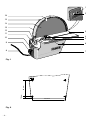
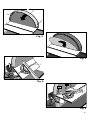
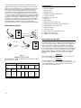
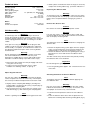
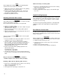
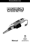
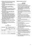
ProxxonTools.com
TG 250/E
Manual
1
2
1
3
6 5
4
16
2
15
14
13
12
3
11
4
5
10
9
6
8
7
Fig. 1
10 mm
80 mm
ø 4,5 mm
Fig. 2
-2-
135 mm
1
2
3
1
Fig. 3
Fig. 4
2
1
Fig. 5
2
1
90°
Fig. 6
-3-
-
Operating Instructions
Disc Sander
Foreword
Dear customer!
The Proxxon TG 250/E disk sander is a high-quality tool
for accurate sanding of a wide variety of materials. Please
read the enclosed safety guidelines and operating instructions to ensure efficient and safe working practices.
This instruction manual covers:
• safety regulations
• operation and maintenance
• spare parts list
Please read carefully!
Using this instruction manual will
• make it easier for you to get used to the machine,
• help prevent faults occurring due to improper use and
• increase the service life of your machine.
Keep this instruction manual in an easily accessible place.
Only operate this machine if you are qualified to do so
and follow the guidelines in this instruction manual.
PROXXON does not accept responsibility for the safe
functioning of the machine
1. if it is handled in a manner which constitutes improper use,
2. if it is used for other purposes which are not specified in the instruction manual,
3. if the safety regulations are not observed.
4. Warranty claims are invalid if the machine is incorrectly operated, or the machine has not been sufficiently maintained.
In the interests of your safety, please always observe the
safety regulations.
Only use genuine PROXXON spare parts.
We reserve the right to make further alterations for the
purpose of technical progress.
We wish you every success with your machine.
-4-
Safety regulations
IMPORTANT
1. Ensure the workplace is tidy.
2. Check the unit for damage before use.
3. (connection cable, protective devices, etc.), have
defective parts replaced by qualified personnel.
4. This unit corresponds to the pertinent safety regulations.
5. Repairs (e.g., replacement of the power supply lead)
may only
6. be performed by a qualified electrician.
7. Never work without the safety equipment fitted.
8. Do not use electrical power tools in the rain, in damp
surroundings or in the vicinity of flammable liquids or
gases.
9. Only use the tool when the handle is dry and free from
grease.
10. Avoid contact with earthed components, e.g., pipes,
radiators, ovens and refrigerators.
11. Protect the connection lead from heat and sharp
edges and
12. route it so it cannot be damaged.
13. Do not remove the plug from the socket by pulling on
the cable.
14. Do not pick up the unit by the cable.
15. Keep children and third parties away from the workplace.
16. Keep tools in childsafe locations when not in use.
17. Do not overload the tool.
18. Do not use the tool to perform operations for which it
is not suitable.
19. Replace blunt tools in good time.
20. Visually inspect application tools to ensure they are in
good working order and suitable for the task prior to
setting up the job.
21. Fasten tools securely.
22. Clean the unit thoroughly following all work.
23. Disconnect the plug from the power supply when the
unit is not in use, before performing maintenance, tool
replacement or repair work.
24. Only plug the unit in when the unit is switched off.
25. Always wear protective goggles (danger of tool breakage).
26. If necessary, wear a protective dust mask.
27. Only use appropriate working clothes (no loose sleeves, ties, jewellery).
28. Wear a hair net if you have long hair.
29. Only use accessories and spare parts recommended
by PROXXON.
30. Observe the max. permitted rotational speed.
31. If necessary, use dust extract equipment.
32. Do not use the tool when you are tired or under the
influence of alcohol.
33. Keep fingers away from rotating or fast moving tools
(saws, etc.).
34. Keep the operation instructions in a safe place.
General safety instructions
Read and become familiar with this entire instructions
manual. Learn the tool`s applications, limitations and
possible hazards.
1. KEEP GUARDS IN PLACE and in working order.
2. REMOVE ADJUSTING KEYS AND WRENCHES. Form
habit of checking to see that keys and adjusting
wrenches are removed from tool before turning it on.
3. KEEP WORK AREA CLEAN. Cluttered areas and
benches invite accidents.
4. DON'T USE IN DANGEROUS ENVIRONMENT. Don't
use power tools in damp or wet locations, or expose
them to rain. Keep work area well lighted.
5. KEEP CHILDREN AWAY. All visitors should be kept
safe distance from work area.
6. MAKE WORKSHOP KID PROOF with padlocks, master
switches, or by removing starter keys.
7. DON'T FORCE TOOL. It will do the job better and safer
at the rate for which it was designed.
8. USE RIGHT TOOL. Don't force tool or attachment to
do a job for which it was not designed.
9. USE PROPER EXTENSION CORD. Make sure your
extension cord is in good condition. When using an
extension cord, be sure to use one heavy enough to
carry the current your product will draw. An undersized
cord will cause a drop in line voltage resulting in loss of
power and overheating. Table 1 shows the correct size
to use depending on cord length and nameplate
ampere rating. If in doubt, use the next heavier gage.
The smaller the gage number, the heavier the cord.
Exception No. 1: The reference to the table and the
table itself may be omitted if a statement indicating the
appropriate gage and length is incorporated into the
instruction.
Exception No. 2: The information regarding extension
cords need not be provided for a permanently
connected tool.
10. WEAR PROPER APPAREL. Do not wear loose clothing,
gloves, neckties, rings, bracelets, or other jewellery
which may get caught in moving parts. Non-slip
footwear is recommended.
Wear protective hair covering to contain long hair.
Exception: The reference to gloves may be omitted
from the instructions for a grinder.
11. ALWAYS USE SAFETY GLASSES. Also use face or
dust mask if cutting operation is dusty. Everyday
eyeglasses only have impact resistant lenses, they are
NOT safety glasses.
12. SECURE WORK. Use clamps or a vise to hold work
when practical. It's safer than using your hand and it
frees both hands to operate tool.
13. DON'T OVERREACH. Keep proper footing and balance
at all times.
14. MAINTAIN TOOLS WITH CARE. Keep tools sharp and
clean for best and safest performance. Follow
instructions for lubricating and changing accessories.
15. DISCONNECT TOOLS before servicing; when changing
accessories, such as blades, bits, cutters, and the like.
16. REDUCE THE RISK OF UNINTENTIONAL STARTING.
Make sure switch is in off position before plugging in.
17. USE RECOMMENDED ACCESSORIES. Consult the
owner's manual for recommended accessories. The
use of improper accessories may cause risk of injury to
persons.
18. NEVER STAND ON TOOL. Serious injury could occur if
the tool is tipped or if the cutting tool is unintentionally
contacted.
19. CHECK DAMAGED PARTS. Before further use of the
tool, a guard or other part that is damaged should be
carefully checked to determine that it will operate
properly and perform its intended function check for
alignment of moving parts, binding of moving parts,
breakage of parts, mounting, and any other conditions
that may affect its operation. A guard or other part that
is damaged should be properly repaired or replaced.
20. DIRECTION OF FEED. Feed work into a blade or cutter
against the direction of rotation of the blade or cutter
only.
21. NEVER LEAVE TOOL RUNNING UNATTENDED. TURN
POWER OFF. Don't leave tool until it comes to a
complete stop.
Warning
For Your Own Safety Read Instruction Manual Before
Operating Sander
Additional safety instructions for sander:
a) Wear eye protection.
b) Support workpiece on worktable.
c) Maintain 1/16 inch maximum clearance between table
and sanding belt or disc.
d) Avoid kickback by sanding in accordance with the
directional arrows.
GROUNDING INSTRUCTIONS:
1. All grounded, cord-connected tools:
In the event of a malfunction or breakdown, grounding
provides a path of least resistance for electric current to
reduce the risk of electric shock. This tool is equipped with
an electric cord having an equipment-grounding conductor
and a grounding plug.
The plug must be plugged into a matching outlet that is
properly installed and grounded in accordance with all
local codes and ordinances. Do not modify the plug
provided – if it will not fit the outlet, have the proper outlet
installed by a qualified electrician.
Improper connection of the equipment-grounding
conductor can result in a risk of electric shock. The
conductor with insulation having an outer surface that is
green with or without yellow stripes is the equipmentgrounding conductor. If repair or replacement of the
electric cord or plug is necessary, do not connect the
equipment-grounding conductor to a live terminal. Check
with a qualified electrician or service personnel if the
grounding instructions are not completely understood,
or if in doubt as to whether the tool is properly grounded.
Use only 3-wire extension cords that have 3prong
grounding plugs and 3pole receptacles that accept the
tool's plug.
Repair or replace damaged or worn cord immediately.
-5-
2. Grounded, cord-connected tools intended for use on a
supply circuit having a nominal rating less than 150 volts:
This tool is intended for use on a circuit that has an outlet
that looks like the one illustrated in Sketch A in Figure 7.
The tool has a grounding plug that looks like the plug
illustrated in Sketch A in Figure 7. A temporary adapter,
which looks like the adapter illustrated in Sketches B and
C, may be used to connect this plug to a 2-pole receptacle
as shown in Sketch B if a properly grounded outlet is not
available. The temporary adapter should be used only until
a properly grounded outlet can be installed by a qualified
electrician. The green-colored rigid ear, lug, and the like,
extending from the adapter must be connected to a
permanent ground such as a properly grounded outlet box.
Legend (fig, 1)
1. Speed controller
2. On/off switch
3. Working table
4. Angular limit stop clamping bolt
5. Angular limit stop
6. Angular limit stop scale
7. Housing
8. Mains cable
9. Spigots for duct extract unit
10. Clamping bolt for working table adjustment
Grounding methods
11. Working table adjustment scale
12. Indicator needle
13. Protective cover
14. Disk sander disk with abrasive disk
15. Spigots for cooling unit
METAL SCREW
16. Spigots for coolant pipes
COVER OF GROUNDED
OUTLET BOX
GROUNDING
PIN
<B>
<A>
Description of the Unit
ADAPTER
GROUNDING
MEANS
<C>
This disk sander can be used to precisely grind all types of
wood, non-ferrous metals, steel, plastic, cork, rubber and
glass. The stepless speed control permits the grinding
characteristics to be optimally matched to any material.
GROUNDING
PIN
<D>
Fig. 7
Warning !
Table 1
Minimum gage for cord
Effective date for Table 1 changed from November 1, 1995
to November 11, 1996
Ampere Rating
More
Than
Volts
Total length of cord in feet
120 V
25 ft.
50 ft.
100 ft.
150 ft.
240 V
50 ft. 100 ft.
200 ft.
300 ft.
14
Not More
Than
AWG
0
6
18
16
16
6
10
18
16
14
12
10
12
16
16
14
12
12
16
14
12
-6-
The working table is manufactured from die-cast aluminium
with a ground surface finish. Self-adhesive abrasive disks
can be readily replaced. The disk sander has dual ballbearing mounts and the front face of the unit is planeturned.
Not Recommended
This Disk sander is for indoor use only. Do not expose to
rain or use in damp locations.
Warning !
For your safety, never connect the plug to the power
source receptacle until the assembly and adjustment steps
are completed, and you have read and understood the
safety and operating instructions.
Technical data
3. Grind a piece of wood and check the angle, if necessary
readjust the working table 3 (fig. 1) and the indicator 12.
Grinding speed:
Abrasive disk:
Max. grinding height:
Table adjustment:
Noise level:
Vibration:
Working table:
Overall size:
250 - 750 m/min
Ø 250 mm
135 mm
15° upwards, 45° downwards
72 dB(A)
2.5 m/s2
275 x 105 mm
330 x 280 x 230 mm
Replacing the Abrasive Disk
Warning!
To avoid injury from accidental start, make sure the switch
is in the OFF position and the plug is not connected to the
power source receptacle before changing any parts or
discs.
Motor:
Voltage:
Power consumption:
115 V / 60 Hz
200 Watt
Remove the abrasive disk
Caution!
Disconnect the mains plug from the power socket.
Unit Assembly
Warning!
Warning !
To avoid injury from unexpected starting or electrical
shock, do not plug the power cord into a power source
receptacle during unpacking and assembly. This cord must
remain unplugged whenever you are working on the disk
sander.
Warning!
If any part is missing or damaged, do not plug the disk
sander in until the missing or damaged part is replaced,
and assembly is complete. To avoid electrical shock, use
only identical replacement parts when servicing double
insulated tools.
Warning!
Do not attempt to modify this tool or create accessories
not recommended for use with this tool. Any such
alternation or modification is misuse and could result in
hazardous condition leading to possible serious injury.
1. Remove the disk sander from the packaging and check
if any parts are missing.
2. Fasten unit using fastening bolts onto a stable
workbench or working surface, as per fig. 2.
For your own safety, use only abrasive discs sized and
recommended for this disk grinder. Follow the instructions
that accompany the disk grinder.
Note:
The protective cover must be removed when changing the
abrasive disk.
1. Detach the liquid cooling system pipes from the spigots
3 (fig. 3) on the protective cover if present. Release the
fastening bolts 1 and remove the protective cover 2.
2. Detach the abrasive disk from the grinding plate using a
blunt knife or a chisel and remove the abrasive disk
halfway.
The disk can be easily removed from the plate by heating
the adhesive with a hot-air blower.
Important!
Do not damage the grinding plate!
3. Turn the grinding plate approx. 180° and remove the rest
of the disk.
Adjust Angular Indicator
Attaching New Sheet of Abrasive Material
Warning!
For your own safety, do not plug the tool into the power
source receptacle or insert the switch key, until the parts
are correctly installed and adjustments have been made.
1. Slightly release clamping bolt 10 (fig.1) and align the
working table 3 to precisely 90° (using a square) (fig. 6).
Retighten the clamping bolt.
2. Check and if necessary correct the zero setting of the
indicator 12 (fig. 1), after releasing the clamping bolts.
Note:
Perform a grinding test before performing precision work.
Note:
Thoroughly clean the grinding plate before applying the
new abrasive disk.
Warning!
Use only accessories recommended for this disk sander.
Follow the instructions that accompany accessories. Use
of improper accessories may cause hazards.
1. Pull off half of the protective foil for the new abrasive
disk.
2. Insert the abrasive disk halves with the protective foil
between the working table and the grinding plate (fig. 4).
-7-
Note:
When applying the abrasive disk on the grinding plate,
start from the centre and work outwards.
3. Apply the top half of the abrasive disk on the grinding
plate precisely in the correct position.
4. Rotate the grinding plate approx. 180°, remove the
second half or the protective foil and use the same
procedure to apply the disk.
5. Reattach the protective cover.
Working with the Disk sander
Important!
Safe and precision working practice can only be ensured
with the unit properly secured!
Do not leave the unit switched on if unsupervised.
1. Switch on the disk sander.
2. Adjust the rotational speed of the disk sander using the
speed controller 1 (fig. 1).
3. Place the work piece on the working table, guide it
gently and carefully.
4. Always exert pressure on the working table rather than
against the abrasive disk.
Note:
Please note the following items in order to ensure good
grinding results:
With horizontally set working table
1. Release the clamping bolt 2 (fig. 6) and set the working
table horizontally (indicator at "0").
2. Tighten clamping bolt 2.
3. Set the angular limit stop 1 (fig. 6) to the desired angle
(e.g., 45°).
Liquid Cooling System
We recommend that the liquid cooling system is attached
when grinding iron, steel and non-ferrous metals, as well
as stone, tiles, ceramics (not included in scope of supply,
available as an accessory).
The heat arising from grinding operations is dissipated by
supplying coolant, thus improving the resulting surface
quality.
Dust Extract Connection
In order to permit a dust-free working environment, the
disk sander is equipped with a vacuum cleaner connection
for dust extraction.
Important!
1. Do not overload the unit (if the fuse blows, only use an
original fuse (1.25 T) as a replacement)!
When using both a vacuum cleaner (as a dust extract unit)
and the liquid cooling unit, ensure that the vacuum cleaner
is suitable for aqua cleaning as well.
2. The disk sander is primarily designed for grinding
precise angles. The more accurately the work piece is
pre-cut, the quicker and easier it will be to produce
precise angles and the less abrasive disks will be
required to perform the task.
1. Connect the vacuum cleaner hose to the connection
spigot 9 (fig. 1).
2. Switch on the vacuum cleaner.
3. Switch on the disk sander, grind the work piece.
3. Please note the dissimilar grinding speeds for the
abrasive disk (fig. 6):
inner diameter = low speed
outer diameter= high speed
4. The abrasive disk turns in an anti-clockwise direction.
For this reason, only grind on the left half of the working
table.
Important!
Only use abrasive disks which are in a flawless
condition. Replace worn abrasive disks promptly.
Grinding a Mitre with the Working Table Inclined
1. Release the clamping bolt 2 (fig. 5) and set the working
table to the desired angle (e.g., 45°).
2. Tighten clamping bolt 2.
3. Set angular limit stop 1 (fig. 5) to position "0"
-8-
Cleaning and Care
Your disk sander was developed for minimal maintenance,
however regular cleaning is required to ensure a long
trouble-free service life.
Caution!
Always disconnect the mains plug prior to cleaning and
maintenance operations.
1. Regularly inspect the mains cable for damage.
2. Ensure the abrasive disk is securely seated and in
perfect condition, if necessary replace the abrasive disk.
3. Thoroughly clean the disk sander after use.
Warning!
To avoid fire or toxic reaction, never use gasoline, naphtha,
acetone, lacquer thinner, or similar highly volatile solvents
to clean the disk sander.
Do not allow brake fluids, gasoline, or penetrating oils to
come in contact with the plastic parts. They contain
chemicals that can damage or destroy plastics.
Turn switch OFF and always remove plug from power
source before making any adjustments or repairs.
All electrical or mechanical repairs should be done only by
qualified service technicians.
When servicing use only PROXXON replacement parts.
Use of any other parts may create a hazard or cause
product damage.
Any attempt to repair or replace electrical parts on this disk
sander may create a hazard unless repair is done by a
qualified service technician. Repair service is available at
your PROXXON service center (You find the address at
address at the back of this manual)
-9-