1
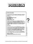
DB 250
1
2
0
5
3
4
Manual
19
1
2
3
8
5 6
1
2
0
5
3
4
4
7
9
14
13
11
Fig. 1
12
10
1
2
0
5
3
4
1
3
2
4
Fig. 2
Fig. 3
Fig. 4
-2-
Fig. 5
2
1
1
3
2
Fig. 6
Fig. 7
Fig. 8
Fig. 9
1
2
Fig. 10
-3-
Fig. 11
Operating Instructions
DB 250
Instructions for the use of the Micro wood
turning lathe DB 250
Dear Customer,
In order to be able to operate the wood turning lathe
safely and correctly, please carefully read the following
safety and operating instructions prior to use.
This instruction manual covers:
• safety regulations
• operation and maintenance
• spare parts list
Please read carefully and become familiar with this entire
instructions manual. Learn the tool´s applications, limitations and possible hazards.
Using this instruction manual will
• make it easier for you to get used to the machine,
• help prevent faults occurring due to improper use and
• increase the service life of your machine.
Keep this instruction manual in an easily accessible
place. Only operate this machine if you are qualified to do
so and follow the guidelines in this instruction manual.
PROXXON does not accept responsibility for the safe
functioning of the machine
• if it is handled in a manner which constitutes improper use,
• if it is used for other purposes which are not specified in
the instruction manual,
• if the safety regulations are not observed.
Warranty claims are invalid if
• the machine is incorrectly operated,
• the machine has not been sufficiently maintained.
In the interests of your safety, please always observe the
safety regulations.
Only use genuine PROXXON spare parts.
We reserve the right to make further alterations for the
purpose of technical progress.
We wish you every success with your machine.
Safety instructions
1. KEEP GUARDS IN PLACE and in working order.
2. REMOVE ADJUSTING KEYS AND WRENCHES.
Form habit of checking to see that keys and adjusting
wrenches are removed from tool before turning it on.
3. KEEP WORK AREA CLEAN. Cluttered areas and
benches invite accidents.
4. DON’T USE IN DANGEROUS ENVIRONMENT. Don’t
use power tools in damp or wet locations, or expose
them to rain. Keep work area well lighted.
5. KEEP CHILDREN AWAY. All visitors should be kept
safe distance from work area.
6. MAKE WORKSHOP KID PROOF with padlocks,
master switches, or by removing starter keys.
7. DON’T FORCE TOOL. It will do the job better and
safer at the rate for which it was designed.
8. USE RIGHT TOOL. Don’t force tool or attachment to
do a job for which it was not designed.
-4 -
9. USE PROPER EXTENSION CORD. Make sure your
extension cord is in good condition. When using an
extension cord, be sure to use one heavy enough to
carry the current your product will draw. An
undersized cord will cause a drop in line voltage
resulting in loss of power and overheating. Table 1
shows the correct size to use depending on cord
length and nameplate ampere rating. If in doubt, use
the next heavier gage. The smaller the gage number,
the heavier the cord.
10. WEAR PROPER APPAREL. Do not wear loose
clothing, gloves, neckties, rings, bracelets, or other
jewelry which may get caught in moving parts.
Nonslip footwear is recommended. Wear protective
hair covering to contain long hair.
Exception: The reference to gloves may be omitted
from the instructions for a grinder.
11. ALWAYS USE SAFETY GLASSES. Also use face or
dust mask if cutting operation is dusty. Everyday
eyeglasses only have impact resistant lenses, they
are NOT safety glasses.
12. SECURE WORK. Use clamps or a vise to hold work
when practical. It’s safer than using your hand and it
frees both hands to operate tool.
13. DON’T OVERREACH. Keep proper footing and balance at all times.
14. MAINTAIN TOOLS WITH CARE. Keep tools sharp
and clean for best and safest performance. Follow instructions for lubricating and changing accessories.
15. DISCONNECT TOOLS before servicing; when
changing accessories, such as blades, bits, cutters,
and the like.
16. REDUCE THE RISK OF UNINTENTIONAL
STARTING. Make sure switch is in off position before
plugging in.
17. USE RECOMMENDED ACCESSORIES. Consult the
owner’s manual for recommended accessories. The
use of improper accessories may cause risk of injury
to persons.
18. NEVER STAND ON TOOL. Serious injury could occur
if the tool is tipped or if the cutting tool is unintentionally contacted.
19. CHECK DAMAGED PARTS. Before further use of the
tool, a guard or other part that is damaged should be
carefully checked to determine that it will operate properly and perform its intended function – check for
alignment of moving parts, binding of moving parts,
breakage of parts, mounting, and any other
conditions that may affect its operation.
A guard or other part that is damaged should be properly repaired or replaced.
20. DIRECTION OF FEED. Feed work into a blade or
cutter against the direction of rotation of the blade or
cutter only.
21. NEVER LEAVE TOOL RUNNING UNATTENDED.
TURN POWER OFF. Don’t leave tool until it comes to
a complete stop.
22. WHEN SERVICING USE ONLY IDENTICAL
REPLACEMENT PARTS.
23. TO REDUCE THE RISK OF ELECTRIC SHOCK,
THIS EQUIPMENT HAS A POLARIZED PLUG. (One
blade is wider than the other). This plug will fit in a
polarized outlet only one way. If the plug does not fit
fully in the outlet, reverse the plug. If it still does not fit,
contact a qualified electrician to install the proper
outlet. Do not change the plug in any way.
Additional safety instructions for wood lathes:
Table 1:
Minimum gage for cord:
Total length of
cord in feet
25 ft
50 ft
100 ft
150 ft
AWG:
18
16
16
14
Additional safety instructions:
• Ensure the workplace is tidy.
• Check the unit for damage before use• (connection
cable, protective devices, etc.), have defective parts
replaced by qualified personnel.
• This unit corresponds to the pertinent safety regulations.
Repairs (e.g., replacement of the power supply lead)
may only be performed by a qualified electrician
• Never work without the safety equipment fitted.
• Do not use electrical power tools in the rain, in damp
surroundings or in the vicinity of flammable liquids or
gases.
• Only use the tool when the handle is dry and free from
grease.
• Avoid contact with earthed components, e.g., pipes, radiators, ovens and refrigerators.
• Protect the connection lead from heat and sharp edges
and route it so it cannot be damaged.
• Do not remove the plug from the socket by pulling on
the cable.
• Do not pick up the unit by the cable.
• Keep children and third parties away from the workplace.
• Keep tools in childsafe locations when not in use.
• Do not overload the tool.
• Do not use the tool to perform operations for which it is
not suitable.
• Replace blunt tools in good time.
• Visually inspect application tools to ensure they are in
good working order and suitable for the task prior to
setting up the job.
• Fasten tools securely.
• Clean the unit thoroughly following all work
• Disconnect the plug from the power supply when the
unit is not in use, before performing maintenance, tool
replacement or repair work.
• Only plug the unit in when the unit is switched off.
• Always wear protective goggles (danger of tool
breakage).
• If necessary, wear a protective dust mask.
• Only use appropriate working clothes (no loose sleeves,
ties, jewellery).
• Wear a hair net if you have long hair.
• Only use accessories and spare parts recommended by
PROXXON
• Observe the max. permitted rotational speed
• If necessary, use dust extract equipment
• Do not use the tool when you are tired or under the influence of alcohol.
• Keep fingers away from rotating or fast moving tools
(saws, etc.).
• Keep the operation instructions in a safe place.
1.
2.
3.
4.
5.
6.
7.
8.
9.
Wear eye protection.
Tighten all locks before operating.
Rotate workpiece by hand before applying power.
Rough out workpiece before installing on faceplate.
Do not mount split workpiece or one containing knot.
Use lowest speed when starting new workpiece.
Remove the mains plug for all adjustment work!
Always wear protective goggles!
Do not wear loose gloves or any loose clothing when
working on the lathe!
10. Do not use any grossly out-of-centre non-machined
parts.
3 Grounding instructions
In the event of a malfunction or breakdown, grounding
provides a path of least resistance for electric current to
reduce the risk of electric shock. This tool is equipped
with an electric cord having an equipment-grounding
conductor and a grounding plug. The plug must be
plugged into a matching outlet that is properly installed
and grounded in accordance with all local codes and ordinances.
Do not modify the plug provided – if it will not fit the outlet, have the proper outlet installed by a qualified electrician.
Improper connection of the equipment-grounding conductor can result in a risk of electric shock. The conductor with insulation having an outer surface that is green
with or without yellow stripes is the equipment-grounding
conductor. If repair or replacement of the electric cord or
plug is necessary, do not connect the equipmentgrounding conductor to a live terminal.
Check with a qualified electrician or service personnel, if
the grounding instructions are not completely understood, or if in doubt as to whether the tool is properly
grounded. Use only 3-wire extension cords that have 3prong grounding plugs and 3-pole receptacles that accept the tool’s plug.
Repair or replace damaged or worn cord immediately.
This tool is intended for use on a circuit that has an outlet
that looks like the one illustrated in Sketch A in Figure 6.
The tool has a grounding plug that looks like the plug illustrated in Sketch A in Figure 6. A temporary adapter,
which looks like the adapter illustrated in Sketches B and
C, may be used to connect this plug to a 2-pole receptacle as shown in Sketch B if a properly grounded outlet is
not available. The temporary adapter should be used only until a properly grounded outlet can be installed by a
qualified electrician. The green-colored rigid ear, lug, and
the like, extending from the adapter must be connected
to a permanent ground such as a properly grounded outlet box.
WARNING:
Some dust created by power sanding, sawing, grinding,
drilling, and other construction activities contains chemicals known to the State of California to cause cancer,
birth defects or other reproductive harm. Some examples
of these chemicals are:
-5-
Technical data
METAL SCREW
COVER OF GROUNDED
OUTLET BOX
GROUNDING
PIN
<B>
<A>
Weight:
Noise emission:
ADAPTER
<C>
GROUNDING
MEANS
GROUNDING
PIN
• lead from lead-based paints,
• crystalline silica from bricks and cement and other masonry products, and
• arsenic and chromium from chemically-treated lumber.
Your risk from these exposures varies, depending on how
often you do this type of work. To reduce your exposure
to these chemicals: work in a well ventilated area, and
work with approved safety equipment, such as those
dust masks that are specially designed to filter out
microscopic particles.
Use a vacuum cleaner for wood dust collection as
described in our manual whenever possible.
Description of the machine
You will find the PROXXON Micro wood turning lathe, DB
250 is ideal for turning small workpieces of wood or
similar materials. This lathe is not suitable for working
metals. The basic equipment includes: 6 chucks: 2, 3, 4,
6, 8 and 10 mm (.07, .11, .15, .23, .31, .39 in.), 2 chuck
keys, 1 lathe centre, 1 drive spike, 1 workpiece holder
and 1 centring ruler.
Overall view (Fig. 1):
On/off switch
Speed control
Spanner flats
Spindle with collet chuck
Work piece holder for motor-driven spindle
Support
Base plate
Drive spike
Tailstock with tailstock quill.
Bed
Holes for table fastening
Collet chucks
Check key
Centring ruler
-6-
115 Volt, 50/60Hz
100 W
1.000-5.000/min
ca. 250 mm (9 27/32” in.)
40 mm (1 37/64” in.)
10 mm (13/32” in.)
ca. 490 x 150 x 95 mm
(19,29 x 5,91 x 3,74 in.)
2.2 kg (4,9 lb)
≤ 70 dB (A)
Installation of the wood turning lathe
<D>
1.
2.
3.
4.
5.
6.
7.
8.
9.
10.
11.
12.
13.
14.
Voltage:
Power rating:
Speed:
Centre distance:
Centre height:
Spindle ciearance:
Dimensions:
Before starting work on the wood turning lathe, use the
wood screws to attach the machine to a stable wooden
board. The wooden board can subsequently be fixed to
the table by means of a vice (Fig. 2).
Operation
Fitting round rods in the collet chuck
The collet chucks supplied can be used to easily clamp
round pieces of wood with the following diameters:
5
/64”, 7/64”, 5/32”, 15/64”, 5/16” and 13/32” (2, 3, 4, 6, 8, 10 mm). For
this purpose use the key to block motor-driven spindle 1
(Fig. 3), and unscrew nut 2. Place the requested collet
chuck 3, and slightly attach the nut. Insert work piece 4 in
the collet chuck, and tighten the nut by hand Check for
true running manually. Subsequently, use the second key
to thighten the nut.
Note:
Carefully tension the nut in order to prevent the collet
chuck being damaged!
To this end, please proceed as described in the section
"Clamping of long workpieces" on the next page. Long
work pieces must be provided with additional support on
the tailstock side.
Clamping round wood in the workpiece holder
Clamping round wood that is very thick in relation to its
length:
1. Mark two saw-lines with the centring ruler (fig. 4). Use
a fine saw blade to saw along the lines to a depth of
2 mm.
2. At the point where the two lines cross, bore a hole of
about 2mm dia. and 5 mm depth
3. Position the workpiece on the holder as shown in fig.
5 and scrow it fast.
4. Fix the workpiece with the holder in drive spindle 1,
as described in chapter 1 for the clamping of round
rod.
5. Push tailstock 1 (fig. 6) up to the back end of the
workpiece and clamp it fast to the bed with knurled
nut
6. Turn knurled nut 3 to bring the point into contact with
the workpiece so that it is fixed.
Clamping of long workpieces
(thicker than 10 mm)
1. Insert drive spike 1 (fig. 7) in the drive spindle and
screw it tight (as described in the clamping of round
rod).
2. Push tailstock up to the back end of the workpiece as
shown' in fig. 8 and clamp it fast to the bed with the
knurled nut, exactly as described in the previous
section.
3. Turn the knurled nut to bring the point into contact
with the workpiece so that it is fixed
4. Adjust tool rest 1 so that it is positioned about
2 mm from the workpiece (fig. 9) The holder arm can
be clamped fast in the required position with screw 2.
5. If required, the knurled screw can be loosened in
order to adjust the sideways inclination of the tool
rest.
If plates or similar shapes are to be turned, the work
piece must be screwed down to the holding device (Fig.
5). Ensure that the screws do not protrude from the work
piece after machining.
Risk of injury!
Tip: Particularly short work pieces are fastened by
screwing an intermediate plate to the holding device (as
described above), and attaching the work piece to the
intermediate plate with double sided adhesive tape.
Longitudinal turning
Note!
Prior to turning, always remove centring key 2
(Fig. 4).
1. Check the work piece for true running by turning
manually.
2. Set support 1 (Fig. 9) so that the space is about 2 mm
(.07 in.).
3. Tighten screw 2.
4. When turning, hold the chisel as shown in Fig. 9.
Maintenance
Important
Pull out the mains plug prior to commencing all maintenance and repair work.
Warning!
Turn switch OFF and always remove plug from power
source before making any adjustments or repairs.
If any part is missing or damaged, do not plug the tool in
until the missing or damaged part is replaced, and
assembly is complete. To avoid electrical shock, use only
identical replacement parts when servicing the tool.
Warning!
To avoid fire or toxic reaction, never use gasoline,
naphtha, acetone, lacquer thinner, or similar highly
volatile solvents to clean the Micro wood lathe.
Do not allow brake fluids, gasoline, or penetrating oils to
come in contact with the plastic parts. They contain chemicals that can damage or destroy plastics!
All electrical or mechanical repairs should be done only
by qualified service technicians.
When servicing use only PROXXON replacement parts.
Use of any other parts may create a hazard or cause product damage.
Any attempt to repair or replace electrical parts on this
tool may create a hazard unless repair is done by a
qualified service technician.
Repair service is available at your PROXXON service
center
(You find the address at address at the back of this
manual).
Transverse turning
1. Undo screw 1 (Fig. 10) and turn support 2 by 90
degrees. Allow the support to engage in pad 3.
2. Set the distance from the work piece, and tighten
screw 1 again.
Reworking the work piece
After turning the work piece can be ground with a fine abrasive cloth at medium speed, and coloured designs can
be applied by brush when the machine is operating at
minimum speed.
When grinding, ensure that the abrasive cloth does not
wrap around the workpiece (Fig. 11).
Risk of Injury!
-7-
Spare parts list
Please order spare parts in writing from Proxxon Service
PROXXON MICRO-Wood-Lathe DB 250
Part no.:
Designation
Part no.:
Designation
27020 - 1
27020 - 3
27020 - 4
27020 - 6
27020 - 7
27020 - 8
27020 - 9
27020 - 10
27020 - 11
27020 - 12
27020 - 13
27020 - 14
27020 - 15
27020 - 16
27020 - 17
27020 - 18
27020 - 19
27020 - 20
27020 - 21
27020 - 22
27020 - 23
27020 - 24
27020 - 26
27020 - 27
27020 - 28
27020 - 29
27020 - 30
27020 - 31
27020 - 32
27020 - 33
27020 - 34
27020 - 35
27020 - 36
Plastic mat
Casing, lower part
Toothed belt
Motor belt pulley
Setscrew
Screw
Shaft
Swivel nut
Clamping jaw 2mm (.07 “)
Clamping jaw 3mm (.11 “)
Clamping jaw 4mm (.15 “)
Clamping jaw 6mm (.23 “)
Clamping jaw 8mm (.31 “)
Clamping jaw 10mm (.39 “)
Bearing
Pulley for work spindle
Setscrew
Board
Screw
Potentiometer
Control knob
On-off-switch
Strain relief
Screw for strain relief
Grommet
Screw
Open-end-wrench
Bed
Cover
Screw
Sliding block
Tailstock
Knurled screw
27020 - 37
27020 - 38
27020 - 41
27020 - 46
27020 - 47
27020 - 48
27020 - 49
27020 - 50
27020 - 51
27020 - 52
27020 - 53
27020 - 54
27020 - 55
27020 - 56
37020 - 57
27020 - 58
27020 - 61
27020 - 62
27020 - 63
27020 - 64
37020 - 65
37020 - 66
37020 - 67
37020 - 99
Knurled nut
Knurled screw M3
Work piece holder with journal
Dust protection cap
Screw
Screw
Casing, upper part
Tappet
Screw
Revolving center
Mounting plate
Holder
Washer
Hexagon nut
Motor
Mounting plate
Support for chisel
Wing screw
Wing screw
Centering guide
Power cord incl. Plug (3-pin)
Terminal
Toothed washer
Manual with Security Instructions
LIMITED WARRANTY OF PROXXON POWER TOOLS FOR HOME USE
Prox-Tech, Inc., (“Seller”) warrants to the original purchaser only, that all PROXXON consumer power tools will be free from defects in material
or workmanship for a period of two years from the date of purchase. Seller’s sole obligation and your exclusive remedy under this limited warranty and, to the extent permitted by law, any warranty or condition implied by law, shall be the repair or replacement of parts, without charge,
which are defective in material or workmanship and which have not been misused, carelessly handled, or misrepaired by persons other than
Seller or Authorized Service Station. In the event of a failure of a product to conform to this written warranty, please refer to the Service and Repair section on the back of this manual and take action accordingly. This Limited Warranty does not apply to accessory items such as circular
saw blades, drill bits, router bits, jigsaw blades, sanding belts, grinding wheels and other related items. Damage to the product resulting from
tampering, accident, abuse, negligence, unauthorized repairs or Some states in the U.S. and some Canadian provinces do alterations, unapproved attachments or other causes unrelated to problems with material or workmanship are not covered by this warranty.
Any implied warranties shall be limited in duration to two years from date of purchase. Not allow limitations on how long an implied warranty lasts,
so the above limitation may not apply to you. In no event shall seller be liable for any incidental or consequential damages (including but not limited to liability for loss of profits) arising from the sale or use of this product. Some states in the U.S. and some Canadian provinces do not allow
the exclusion or limitation of incidental or consequential damages; so the above limitation or exclusion may not apply to you. This limited warranty
gives you specific legal rights, and you may also have other rights, which vary from state to state in the U.S., province to province in Canada and
from country to country. This limited warranty applies only to PROXXON power tools sold within the United States of America, Canada, the
commonwealth of Puerto Rico and Mexico. For warranty coverage within other countries contact your local PROXXON Importer.
-8-
-9 -
SERVICE AND REPAIR
Your device does not work properly? Please read the operating
instructions again carefully. If the unit is in fact defective, please
send it to:
Prox-Tech, Inc.
Attn.: PROXXON Service Center
2555 Tate Blvd. S.E.
Hickory, NC 28601
Spare Parts
You can also order any necessary spare parts from our Service
Center at the above address. Please check the article-number
of the tool concerned on the nameplate of the tool and define the
part needed by using the explosion drawing in the manual that
came with the tool. Every part has a specific number (5 digitXX). Please provide us with this number when ordering.
For any further information call us toll free at 1-877-PROXXON
(1-877-776 9966) or visit us on the web at www.proxxon.com/us.
Made in Luxemburg
Distributed in the U. S. by Prox-Tech, Inc.
Art. N r. 37020-99 PR 70371170,5J
Please make sure, that your tool is carefully packaged and include a copy of your dated proof of purchase. You will help us
to react even quicker, if you describe the problem in short and
please don’t forget to include your name, address and daytime telephone number. We will respond in a prompt and
reliable manner.
We reserve the right to make further alterations for the purpose of technical progress.