1
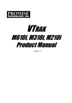
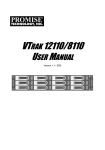
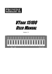
VTrak G-Class Quick Start Guide
1: Unpacking
The VTrak box contains the following items:
• VTrak G1000 NAS Gateway
• Quick Start Guide
• Two 1.5m (4.9 ft) Power cords
• Sliding rail assembly for rack mounting and associated hardware
• Front panel bezel cover
3: Network Connections
2. Determine what height to place
the NAS Gateway in the rack,
then place the right and left rack
rails at the same height on in the
right and left rack position. This
is a 1U server, so choose the
mounting holes accordingly for
your rack system. Consult the
documentation for your rack if you
are unsure which holes to use.
The VTrak G1000 NAS Gateway enables NAS connectivity to the
VTrak A-Class SAN. It is the physical and logical bridge between the
Fibre Channel data network of the VTrak A-Class managed storage and
the NAS clients using connected Ethernet LAN.
Network ports on back panel
Fibre Channel ports
10 Gigabit LAN ports
5
6
• Sheet of Cautions for safety regulation
• Sheet of Cautions for EMC/Safety for Class A product
Caution
* At least two persons are required to safely lift, place, and
attach the device into a rack system.
* Make sure the rack rail cabinet and rack posts are stable
and standing firmly on a level surface.
* Only a qualified technician who is familiar with the
installation procedure should mount and install the
device.
* The rails available for the device are designed to safely
support that unit when properly installed. Additional
loading on the rails is at the customer’s risk.
2: Install in rack
The device installs to the rack using the mounting rails shipped with
the device. The mounting hardware shipped with each NAS Gateway
includes the following items:
1
2
3
4
1 Gigabit LAN ports
a. Press the spring lock then insert the studs into the selected
square holes on the rack post.
Note that the VTrak A-Class head unit must connect to the NAS
Gateway through the 1G LAN ports in order to create the metadata
network used for storage management. This is referred to as the
Management network or Management link in this document.
b. Press the spring lock on the other end of the rail and insert
the studs into the selected mounting hole on the rack post. If
necessary, extend the rail to reach the post.
d. Make sure the rack rail is aligned, secure, stable and in the
correct place.
Important
e. Perform steps a through c above for the other rail.
The NAS Client and Management link to the VTrak A-Class must
be separated logically or physically, so they placed are in different
broadcast domains. For 10G LAN NAS Clients, since two different
switches are used, there is already a physical separation. For 1G LAN
NAS Client setups, it is recommended that two 1G switches be used
to create a physical separation between the 1G Management link
and 1G NAS Client link. If a single 1G switch is used, the switch must
be configured to create the separation logically. The best way to
achieve this is to create one VLAN for the Management network, and
another VLAN for the NAS Client network.
Make sure the rack rails are aligned, secure, stable and in
place. See figure below.
If you intend to use a single 1G LAN switch for the NAS Client and
Management links, please read the Product Manual for detailed
information on cabling layout and VLAN configuration of the 1G
Ethernet switch.
Latch screws, Rail washers, Rail screws
1G LAN Port Link Aggregation options
Follow these steps to install the mounting rails in an equipment rack.
In the Setup Wizard, you are offered three options to configure Link
Aggregation for the Management link from the VTrak A-Class head unit.
Note that the 10G and 1G LAN ports are numbered from left to right
(see illustration above).
4. On the right and left sides of the NAS Gateway, secure the Rail
Latches to the NAS Gateway housing using the latch screws, two
screws for each latch.
1. On the right and left sides of the NAS Gateway, secure the Rail
Latches to the NAS Gateway housing using the latch screws, two
screws for each latch.
•
•
•
Promise Technology, Inc. VTrak G1000 NAS Gateway Quick Start Guide
VTrak_G-Series_QSG_R1.0_FINAL.indd 1
All 1G LAN ports on both units must be connected to a Gigabit Ethernet switch
that completes the Management link to the VTrak A-Class.
To connect the 1G ports, follow these steps:
1.
Attach Category 6 or better Ethernet cables to all ports 1 Gigabit Ethernet
ports on the rear panel of the NAS Gateway.
2.
Attach the other end of the cables to a 1 Gigabit Ethernet switch.
Complete the cable connections for
a 10 Gigabit LAN data network if you
plan to use the 10G LAN for data
connection to NAS clients.
To connect to the 10 Gigabit Ethernet
LAN, follow these steps:
1.
Attach Category 7
(recommended) or Category
6 Ethernet cables to both
10 Gigabit Ethernet ports on
the rear panel of the NAS
Gateway.
2.
Attach the other end of the
cables to the 10 Gigabit Ethernet switch used for the NAS Client network.
The data path from the NAS Gateway to the NAS clients can run on
either the 10G LAN ports, or the 1G LAN ports. For 1G LAN NAS
Client setup especially, careful planning is needed for the cabling
arrangement. See the important notice below.
c. Use the rail screws and washers to anchor the rack rail to the
post.
Right and left sliding rails.
Rail latches
1G Management link
10G NAS Client network
3. Secure the rails to the rack posts. Make sure the rack rails are
properly oriented in the rack. To set the rails into the rack posts
and secure the rails, follow these steps:
f.
Link Aggregation Option 1
1
The first option is for 10G LAN NAS Client setup. In this case all four 1G
LAN ports are aggregated for maximum throughput for the Management
link.
The second option is for 1G LAN NAS Client setups. In this case the 10G
LAN ports are disabled. And ports 1&2 are aggregated for the Management
link, ports 3&4 are aggregated for the NAS Client link. This setup provides a
balance between performance and reliability.
The third option is also for 1G LAN NAS Client setups. The 10G LAN ports
are disabled. Port 1 is used for the Management link, ports 2,3 and 4 are
aggregated for the NAS Client link. This setup provides higher performance
with less reliability.
Link Aggregation Options 2 and 3
1G Management link
Two 1G Ethernet switches
are used, one switch for the
Management link, another switch
for the NAS Client link. Use
Category 6 or better Ethernet
cabling for all 1G Ethernet
connection. To establish the
Management link:
• Link Aggregation Option 2:
Connect 1G LAN ports 1 and
2 on both G1000 devices to
the 1G switch used for the
Management link to the VTrak
A-Class. See illustration
• Link Aggregation Option 3: Connect 1G LAN port 1 on both G1000
devices to the 1G switch used for the Management link to the VTrak
A-Class.
1G NAS Client network
Follow the directions below to establish the NAS Client link according to the Link
Aggregation option you intend to use. Use Category 6 or better Ethernet cables.
• Link Aggregation Option 2: Connect 1G LAN ports 3 and 4 on both G1000
devices to the 1G switch used for the NAS Client network. See illustration
• Link Aggregation Option 3: Connect 1G LAN ports 2, 3 and 4 on both
G1000 devices to the 1G switch used for the NAS Client network.
Version 1.0 PN: G6102VANG000001
2014/10/20 下午 01:38:26
Connect to Fibre Channel data network
The NAS Gateway can be directly attached to VTrak A-Class, or it can
be connected to a Fibre Channel switch that is connected to the VTrak
A-Class. Follow the instructions below for the method you will use.
Via Fibre Channel Switch
4: Connecting the Power
Access Setup Wizard
Insert the female end of one of the supplied power cables in to a power
cable receptacle on each of the power supply units, and plug the other
end in to a suitable power outlet.
The first menu page you see when accessing the NAS Gateway is the
Setup Wizard. Use the Setup Wizard for initial setup, or click Cancel to
go to the main configuration menu for the NAS Gateway.
Power Supply Units on rear panel left end
In the first Setup Wizard menu, provide a NAS Gateway Alias and the
virtual IP address used for the NAS Client link.
Power Supply Status LEDs
For each NAS Gateway device, perform the following.
4. Three Link Aggregation arrangement options are presented.
Choose the option that suits the cabling arrangement and
performance requirements of your network and click Done to
continue. You will be returned to the previous screen. Click Next
to continue.
1. Connect Fibre Channel cables from both Fibre Channel ports on
the rear panel of the NAS Gateway and the Fibre Channel switch.
2. Connect Fibre Channel cables between the Fibre Channel switch
and all Fibre Channel ports on each controller of the partner
VTrak A-Class unit. Note that each controller has four Fibre
Channel ports.
Fibre Channel data network from VTrak A-Class
Power cable receptacles
Notice that choosing options 2 or 3 will disable the 10G LAN ports.
Power on system
1. Configure the following:
• Alias, enter a name for the NAS Gateway.
Before powering on the NAS Gateway, make sure the VTrak A-Class
partner is booted up and running so the G-Class system will be
discovered automatically. Note that the VTrak A-Class must have
firmware version SR2.0 or later for discovery to take place.
•
NAS Gateway Virtual IP Address This Virtual IP address is
shared by all G1000 units in a cluster. All nodes added to the
cluster must have a hard assigned IP address in the same
subnet as the virtual IP address shared by the nodes in the
cluster.
•
For networks using CIFS, click the option box Enable CIFS, and
choose the Default CIFS anonymous user permission.
•
For networks using NFS, click the option box Enable NFS.
VTrak G1000 Power button on front
Directly attached Fibre Channel
Click Next to continue.
For each NAS Gateway device attached directly to the VTrak A-Class
partner system:
1. Attach Fibre Channel cables to both Fibre Channel data ports on
the rear panel of one NAS Gateway, and connect the other end
of one cable to the a Fibre Channel port on one controller of the
partner VTrak A-Class unit. Connect the remaining Fibre Channel
cable to a Fibre Channel port on the other controller of the VTrak
A-Class.
2. Repeat the procedure described in step 1 for the other NAS
Gateway.
3. When completed, each NAS Gateway will be connected to both
controllers on the VTrak A-Class as in the illustration below.
Fibre Channel directly attached to VTrak A-Class
5. In Setup Wizard menu 4, choose the A-Class file system you want
to export to the NAS Gateway. Click Next to continue.
2. Select a node from the list to join the NAS Gateway cluster. Note
that future firmware releases will support clusters with more than
two nodes.
Click Next to continue.
Power button/LED
6. Review the settings in the new menu, click Submit to finish.
To power on the VTrak G1000 simply press the Power button on front
of both devices. Power on both units and check the Power LED and
other LEDs to monitor the boot up process. The Power LED light green
when the system is powered on.
5: Configure NAS Gateway
Management of the NAS Gateway is done through the VTrak A-Class
system. Login as the administrator of the partner VTrak A-Class system
using WebPAM PROe.
3. Click on the Gear icon to display the Link Aggregation menu.
To login:
Gear icon
1. Launch your Browser.
7. The NAS Gateway is now configured for use. Click on Done to
close the Setup Wizard menu.
2. In the Browser address field, type the IP address of the partner
VTrak A-Class head unit.
3. In the main menu, click on the menu tab for the NAS Gateway
to get to the first Setup Wizard menu for setting up the NAS
Gateway.
WebPAM PROe main menu for VTrak A-Class
Important
Setting up LDAP and Microsoft Active Directory for user access is a
bit complicated. Please read the article ‘VTrak A-Class LDAP User
Management – Active Directory’ available online at the PROMISE
Knowledge Base archive. Go to this link:
http://kb.promise.com/KnowledgebaseArticle10398.aspx
Promise Technology, Inc. VTrak G1000 NAS Gateway Quick Start Guide
VTrak_G-Series_QSG_R1.0_FINAL.indd 2
The cluster and node information for
the NAS Gateway should now appear.
Note that it might initially appear with
a red color error status icon. Do not
be concerned since it can take a few
minutes for the status icon to appear
green, indicating normal function.
2
2014/10/20 下午 01:38:42