1
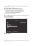
VTRAK
E-Class/J-Class
Quick Start Guide
Version 2.0
Firmware SR2.4
© 2008 Promise Technology, Inc. All Rights Reserved.
VTrak Quick Start Guide
About This Guide
This Quick Start Guide shows you how to install the VTrak E-Class and J-Class in
a rack, how to make management and data connections, and how to power-up,
set-up, and configure the VTrak subsystem.
For information about unpacking the VTrak, see page 3.
For instructions on installing VTrak in a rack, see page 4.
For diagrams and connections for management and data cables, see page 6.
For the system power-up sequence, see page 14.
For making VTrak network settings, see page 16.
For configuring the VTrak automatically using scripts, see page 19.
For safety information, see pages 3 and 4.
Promise periodically releases firmware updates that add functionality to your
VTrak system. You can download the firmware updates from the Promise
Support Website. The firmware update procedure is described in the VTrak
Product (User) Manual on the Software CD.
If you have questions or need assistance, see page 24.
Copyright
© 2008 Promise Technology, Inc. All Rights Reserved.
Copyright by Promise Technology, Inc. (Promise Technology). No part of this
manual may be reproduced or transmitted in any form without the expressed,
written permission of Promise Technology.
Trademarks
Promise, and the Promise logo are registered in U.S. Patent and Trademark
Office. All other product names mentioned herein may be trademarks or
registered trademarks of their respective companies.
2
Task 1: Unpacking the VTrak
VTrak Setup Task List
Task 1: Unpacking the VTrak (page 3)
Task 2: Mounting VTrak in a Rack (page 4)
Task 3: Making Management and Data Connections (page 6)
Task 4: Powering On the System (page 14)
Task 5: Performing the Initial Setup (page 16)
Task 6: Configuring the VTrak (page 19)
For complete information about your VTrak E-Class and J-Class subsystems,
see their respective VTrak Product (User) Manuals on the Software CDs.
Task 1: Unpacking the VTrak
The VTrak box contains the following items:
•
VTrak Unit
•
RJ11-to-DB9 serial data cable
•
Quick Start Guide
•
1.5m (4.9 ft) Power cords (2)
•
Left and right center-mount
brackets
•
•
Left and right mounting rails
Software CD with SNMP files,
Product (User) Manual and Quick
Start Guide
Warning
The electronic components within the VTrak disk array are
sensitive to damage from Electro-Static Discharge (ESD).
Observe appropriate precautions at all times when handling the
VTrak or its subassemblies.
Caution
At least two persons are required to safely lift the VTrak
subsystem from the box and place it into a rack.
Important
Use the following categories of network cables with VTrak:
•
Cat 6, preferred
•
Cat 5E, minimum
3
VTrak Quick Start Guide
Task 2: Mounting VTrak in a Rack
The E-Class subsystem installs to the rack using the supplied mounting rails. You
can also use your existing rails.
Cautions
•
At least two persons are required to safely lift, place, and
attach the VTrak subsystem into a rack.
•
Do not lift or move the VTrak subsystem by the handles,
power supplies or the controller units. Hold the subsystem
itself.
•
Do not install the VTrak subsystem into a rack without rails to
support the subsystem.
•
Only a qualified electrician who is familiar with the installation
procedure should mount and install the VTrak subsystem.
•
Be sure all switches are OFF before you install the VTrak
subsystem or plug in the power.
To install the VTrak subsystem into a rack with the supplied mounting rails:
1.
Check the fit of the mounting rails in your rack system.
2.
Adjust the length of the mounting rails as needed.
3.
Attach the mounting rail assemblies to the outside of the rack posts, using
the attaching screws from your rack system. See Figure 1 on page 5.
Be sure the support is on the bottom facing inward.
4.
Square the rail assemblies in the rack.
5.
Tighten the adjustment screws and the attaching screws.
6.
Place the VTrak subsystem onto the rails.
7.
Secure the VTrak subsystem to the rack through each handle, using the
attaching screws from your rack system.
4
Task 2: Mounting VTrak in a Rack
Figure 1 Rack mount assembly diagram
Rack front post
Rack back post
Rail attaching screw
(not included)
Rail attaching screw
(not included)
Front rail
Rear rail
Flange
Support
Rail adjustment screw
Rail adjustment screw
Inside of post
Inside of post
8.
Remove the drive carriers from their packing and install them into the drive
bays of the VTrak enclosure. See Figure 2
9.
Plug in the power supply cords.
Figure 2
VTrak mounted in a rack with the supplied rails
Drive bay (1 of 16)
Handles mount
outside the rack post
Mounting rails (included)
mount outside the rack post
5
VTrak Quick Start Guide
Task 3: Making Management and Data Connections
VTrak E-Class models have one or two RAID controllers. Each controller has an
Ethernet (RJ45) Management Port connector that enables you to monitor the
VTrak over your network using the WebPAM PROe Software. The VTrak
supports HTTP, HTTPS, and Telnet protocols.
The VTrak RAID controllers have two 4-Gb Fibre Channel (FC) connections for
the data ports. See Figure 3.
You can configure your VTrak for:
•
Storage Area Network (SAN)
•
Direct Attached Storage (DAS)
•
Expansion chassis using SAS data connections
Figure 3
VTrak E-Class RAID controller connector
Fibre Channel data port 2
RJ11 Serial
Connector
Fibre Channel data port 1
Mgmt
FC 1
4
Mgmt
4
2
FC 2
1
1
Gb/s
Gb/s
Mgmt
UPS
FC 1
2
1
Gb/s
115200
8N1
Management port
4
1
Gb/s
UPS
4
2
SAS expansion port
(to J-Class)
FC 1
FC 2
2
4
2
115200
8N1
FC 2
UPS
4
2
1
1
Gb/s
Gb/s
115200
8N1
VTrak E-Class
When you require more than 16 hard disk drives for your storage system, you
can add capacity by connecting up to four VTrak J-Class expansion chassis. See
Figure 4 on page 7.
6
Task 3: Making Management and Data Connections
Figure 4
VTrak J-Class I/O Module
Circle Icon
Diamond Icon RJ11 Serial Connector
115200
8N1
SAS data ports
115200
8N1
115200
8N1
VTrak J-Class
To connect a VTrak E-Class subsystem to a VTrak J-Class expansion chassis:
1.
Find the SAS data cables that ship with the J-Class.
2.
Connect one end of a SAS data cable to the SAS expansion port on the
VTrak E-Class RAID controller. See Figure 5 on page 8.
3.
Connect the other end of the SAS data cable to the Diamond icon SAS port
on the VTrak J-Class I/O module. See Figure 5 on page 8.
4.
If your VTrak E-Class has dual RAID controllers and your VTrak J-Class has
dual I/O modules, connect a second SAS data cable between the other
RAID controller and I/O module in the same manner.
5.
Optional. If your system has multiple VTrak J-Class expansion chassis,
connect their SAS data cables:
•
From the Circle icon SAS port on the I/O module of the First VTrak
J-Class
•
To the Diamond icon SAS port on the I/O module of the Second VTrak
J-Class
See Figure 5 on page 8 and Figure 6 on page 9.
Be sure all of your SAS data connections are Circle-to-Diamond.
7
VTrak Quick Start Guide
Figure 5
Circle Icon
J-Class expansion SAS data connections, dual I/O modules
SAS Expansion Ports
Mgmt
FC 1
4
2
Circle
Icon
FC 2
Mgmt
UPS
FC 1
4
1
Gb/s
4
2
2
1
Gb/s
Circle Icon
115200
8N1
Diamond
Icon
115200
8N1
Diamond
Icon
115200
8N1
FC 2
UPS
4
2
1
1
Gb/s
Gb/s
115200
8N1
VTrak E-Class
115200
8N1
VTrak J-Class
115200
8N1
VTrak J-Class
8
Task 3: Making Management and Data Connections
Figure 6
Circle Icon
J-Class expansion SAS data connections, single I/O modules
SAS Expansion Port
Mgmt
FC 1
4
2
Circle
Icon
FC 2
UPS
4
2
1
1
Gb/s
Gb/s
115200
8N1
Diamond
Icon
VTrak E-Class
115200
8N1
Diamond
Icon
VTrak J-Class
115200
8N1
VTrak J-Class
9
VTrak Quick Start Guide
Configuring a Storage Area Network
A storage area network (SAN) requires:
•
A Fibre Channel switch
•
A Fibre Channel HBA card in the Mac Pro or Xserve
•
An Ethernet switch
Data Paths
To establish the data paths:
1.
Connect one or both of the Fibre Channel ports on each VTrak controller to
your Fibre Channel switch.
2.
Connect two or four Fibre Channel ports on the Mac to your Fibre Channel
switch.
Management Path
To establish the management path:
1.
Connect the Management port on the VTrak controller to your network
switch. Figure 7 below and Figure 8 on page 11.
2.
Connect each Mac’s NIC to your network switch.
Figure 7
SAN data and management connections, dual controller
Ethernet Switch
Fiber Channel Switch
Management
cables
Mgmt
FC 1
4
2
Mac
FC data cables
FC 2
UPS
4
2
1
1
Gb/s
Gb/s
Mgmt
FC 1
4
2
115200
8N1
FC 2
UPS
4
2
1
1
Gb/s
Gb/s
115200
8N1
VTrak
A two-path connection, as shown above, is the minimum requirement for VTrak.
Use a four-path connection for best performance and no single point of failure.
10
Task 3: Making Management and Data Connections
Figure 8
SAN data and management connections, single controller
Ethernet Switch
Fiber Channel Switch
Management
cables
Mgmt
FC 1
4
2
Mac
FC data cables
FC 2
UPS
4
2
1
1
Gb/s
Gb/s
115200
8N1
VTrak
A two-path connection, as shown above, is the minimum requirement for VTrak.
11
VTrak Quick Start Guide
Configuring Direct Attached Storage
Direct attached storage (DAS) requires:
•
A Fibre Channel HBA card in the Mac Pro or Xserve
•
An Ethernet switch
Data Paths
To establish the data paths:
Connect one or both of the Fibre Channel ports on each VTrak controller to
the Fibre Channel card in your Mac.
Management Path
To establish the management path:
1.
Connect the Management port on the VTrak controller to your network
switch. See Figure 9 below and Figure 10 on page 13.
2.
Connect the Mac’s NIC to your network switch.
Figure 9
DAS data and management connections, dual controller
Ethernet Switch
Management
cables
2
1
Mac
FC data cables
Mgmt
FC 1
4
2
FC 2
Mgmt
UPS
FC 1
4
2
1
1
Gb/s
Gb/s
4
2
115200
8N1
FC 2
UPS
4
2
1
1
Gb/s
Gb/s
115200
8N1
VTrak
12
Task 3: Making Management and Data Connections
Figure 10 DAS data and management connections, single controller
Ethernet Switch
Management
cables
2
1
Mac
FC data cables
Mgmt
FC 1
4
2
FC 2
UPS
4
2
1
1
Gb/s
Gb/s
115200
8N1
VTrak
13
VTrak Quick Start Guide
Task 4: Powering On the System
There is a specific sequence to follow when you power on your VTrak and Mac
system. See Figure 11 below or Figure 12 on page 15.
Power on your system components in the following sequence:
1.
All VTrak J-Class expansion chassis
2.
The VTrak E-Class subsystem
3.
The Mac Client
The VTrak takes a few minutes to fully boot-up and become available to the host.
Figure 11 VTrak and Mac power-on sequence, dual controller
Mgmt
FC 1
4
2
FC 2
UPS
4
2
1
1
Gb/s
Gb/s
115200
8N1
14
Mgmt
FC 1
4
2
115200
8N1
FC 2
UPS
4
2
1
1
Gb/s
Gb/s
115200
8N1
115200
8N1
Task 4: Powering On the System
Figure 12 VTrak and Mac power-on sequence, single controller
Mgmt
FC 1
4
2
FC 2
UPS
4
2
1
1
Gb/s
Gb/s
115200
8N1
115200
8N1
15
VTrak Quick Start Guide
Task 5: Performing the Initial Setup
The VTrak’s default network settings are DHCP enabled. The Bonjour service on
the VTrak enables your Safari browser to find the VTrak on the network and
establish a connection automatically.
Establishing a Connection with VTrak
To establish an Ethernet connection between your Mac and the VTrak:
1.
Be sure the VTrak is connected to the network and powered on.
See “Task 3: Making Management and Data Connections” on page 6 and
“Task 4: Powering On the System” on page 14.
2.
3.
On your Mac Desktop, launch Safari.
In Safari, click the Show all bookmarks icon.
See Figure 13.
Figure 13 Show all bookmarks icon
Click the Show all
bookmarks icon.
The Collections list appears. See Figure 14 on page 17.
4.
Under the Collections list, click the Bonjour icon.
The Bonjour links appear in the Bookmarks list. Each VTrak on your network
is listed by its World Wide Node Name (WWNN).
16
Task 5: Performing the Initial Setup
Figure 14 VTrak WWNNs in the Bookmarks list
Click the
Bonjour icon.
Click to highlight the
VTrak you want to
connect.
5.
Click to highlight the WWNN of the VTrak to which you want to connect.
6.
When the log-in screen appears:
•
Type administrator in the User Name field.
•
Type password in the Password field.
•
Click the Login button.
The User Name and Password are case sensitive.
See Figure 15 on page 18.
17
VTrak Quick Start Guide
Figure 15 WebPAM PROe log-in screen
Verifying VTrak’s Network Settings
To verify the VTrak’s network settings:
1.
Click the + icon beside
Then click
2.
Administrative Tools.
Network Management.
In the Management Port tab, click the Port Configuration Link.
Figure 16 VTrak Network settings
The VTrak’s network settings are shown on the Management Port tab.
18
Task 6: Configuring the VTrak
Task 6: Configuring the VTrak
The VTrak supports a wide range of RAID levels, cache settings, and volume
configurations. See the VTrak E-Class Product (User) Manual for more
information.
Apple provides a number of tested and supported configuration scripts to simplify
system configuration for most common storage applications using Mac OS X,
including Xsan configurations. These scripts automatically configure a new VTrak
system for best performance.
Visit Apple’s Knowledge Base at http://support.apple.com/kb/HT1200 for
configuration scripts and directions on applying them.
Preparing Your Script
To prepare your configuration script:
1.
Double-click this link http://support.apple.com/kb/HT1200.
The scripts are listed under Configure via script.
2.
Carefully read the descriptions and choose the script that matches your
application. Click the script name to choose it.
3.
Highlight the entire script from #Begin Copy through #End Copy, then press
a-C to copy it.
4.
Open TextEdit and press a-V to paste the script into a new file.
5.
From the dropdown menu, choose Format > Make Plain Text.
Be sure you convert the configuration script to a plain text file.
6.
Choose File > Save As, name the script file, and click the Save button.
Your configuration script is ready to import using WebPAM PROe.
Checking Your Physical Drives
The configuration script only works when all of your physical drives are
unconfigured. If you are setting up your VTrak system for the first time, all of your
drives will be unconfigured.
To check your physical drives:
1.
If WebPAM PROe is not running, launch Safari and log into WebPAM PROe
as described in “Task 5: Performing the Initial Setup” on page 16.
2.
In Tree View, click
Drives.
3.
Under the Information tab, look at the Operational Status and Configuration
of each physical drive.
VTrak,
Enclosures,
19
Enclosure, and
Physical
VTrak Quick Start Guide
If Operational Status is OK and Configuration is Unconfigured, your
physical drives are ready to run the configuration script.
Figure 17 Physical drive information
Operational Status and
Configuration Status
If you have created any disk arrays, logical drives, or spare drives, you must
delete them before you run the script. Be sure you back-up your important data
first, then delete the disk arrays and logical drives. See the VTrak E-Class
Product (User) Manual for instructions.
20
Task 6: Configuring the VTrak
Importing and Running a Configuration Script
To import and run your configuration script:
1.
In Tree View, click
Administrative Tools, then click the Import link.
Figure 18 The Import link under Administrative Tools
Import link
2.
In the Import File dialog box, choose Configuration Script from the Type
dropdown menu.
Figure 19 Import File dialog box
3.
In the Import File dialog box, click the Choose File button and navigate to
the folder where you saved the configuration file. Click the configuration file
and click the Choose button.
21
VTrak Quick Start Guide
Figure 20 Choosing the configuration file
4.
In the Import File dialog box, click the Submit button.
Figure 21 Clicking the Submit button
5.
In the Import File dialog box, click the Next button.
Figure 22 Clicking the Next button
6.
In the Warning box, click the OK button.
See Figure 23 on page 23.
22
Task 6: Configuring the VTrak
Figure 23 Warning box
The configuration script takes about 30 to 45 seconds to upload and run.
When the script is done, new disk arrays and logical drives appear in
Tree View.
Figure 24 An example of Tree View after running a configuration script
Disk arrays
and logical
drives have
been added
The exact appearance of Tree View depends upon how you set up your
system and which script you chose.
Your VTrak system is now configured and ready to use.
Click
Logical Drives Summary in Tree View to see the full representation
of your new logical drives.
23
VTrak Quick Start Guide
Contacting Technical Support
For assistance or more information:
•
Go to the Promise Support Website at
http://www.promise.com/support/support_eng.asp
•
Go to Promise E-mail Support at e-Support On-Line
•
Contact the nearest Promise Technical Support Office
United States
Fax Support
+1 408 228 1100 Attn: Technical Support
Phone Support
+1 408 228 1400 option 4
The Netherlands
Fax Support
+31 0 40 256 9463 Attn: Technical Support
Phone Support
+31 0 40 235 2600
Germany
Fax Support
+49 0 2 31 56 76 48 29 Attn: Technical Support
Phone Support
+49 0 2 31 56 76 48 10
Taiwan
Fax Support
+886 3 578 2390 Attn: Technical Support
Phone Support
+886 3 578 2395 ext. 8822 or 8823
24