1
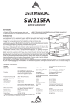
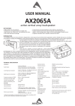
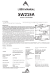
USER MANUAL
SW215FP
passive subwoofer
KEY FEATURES
• Very High Output
• Compact size for a very good output-to-weight ra o
• Manifolded Transmission Line configura on for very fast transient response
• Flying ver cal arrayable version
INTRODUCTION
The SW215FP subwoofer is designed to deliver high quality low frequency reproduc on where
very high output is a key requirement, together with well defined deep bass response and fast
transient response. Its compact size and light weight make it suitable for several different uses,
ranging from touring applica ons to fixed installa ons and high-level dance clubs.
The SW215FP is a very high quality powered subwoofer system featuring some of the most
advanced technologies for low frequency reproduc on. Its unique and innova ve design is based
on a configura on that can be defined as Manifolded Transmission Line.
It uses manifolding of the front side of the cones to maximize the mutual coupling between the
two drivers, while loading the back of the cone with a large-size transmission line that has the
func on to create a transmission path from the back of the transducers to the front.
The SW215FP subwoofer system is equipped with two high power 15” (380mm) transducers
capable of long excursion (up to 33mm peak-to-peak), controlled by high s ffness Double Silicon
Spider as centering suspension and by heavy duty surround. The motor structure features high
strength (BL²/Re) with op mized symmetry and excursion controlled by Aluminium Demodula ng
Ring. The robust copper 75mm (3”) voice coil is wounded in two different layers both outside and
inside the coil support, then doubling the coil surface exposed to air cooling and consequently
improving the long term thermal capacity of the loudspeaker. Cones are made of very high-s ffness
reinforced paper, featuring also invisible water repellent treatment.
TECHNICAL SPECIFICATION
AcousƟcal
System type
Transducer
Connectors
Manifolded Band Pass
Two 15” (380 mm), 3” (75 mm) VC,
High s ffness water repellent reinforced
cone, Flux Demodula ng Ring VC,
Double Centering Spider Suspension
Frequency response (±3 dB)
Frequency range (±10 dB)
Sensi vity (1.41V @ 1m, 2Pi)
Maximum Peak SPL @ 1m
Electrical
Nominal Impedance
Minimum Impedance
Power Handling Con nuous*
8Ω+8Ω
6.1 Ω + 6.1 Ω @ 41Hz
700 W + 700 W
Power Handling Program
900 W + 900 W
Power Handling Peak
2100 W + 2100 W
Power Compression
@ -10 dB Power (180 W + 180 W) = 0.8 dB
@ -3 dB Power (900 W + 900 W) = 1.5 dB
@ 0 dB Power (1800 W + 1800 W) = 2.7 dB
* AES Pink Noise Power
revision 2014-12-5
39 Hz – 120 Hz (Processed)
35 Hz – 300 Hz (Unprocessed)
102dB (averaged from 40 to 100Hz)
139 dB
Connector Type
Neutrik® Speakon® NL4 x 2
Input Wiring
LF1 = Pin 1+/-; LF2 = Pin 2+/-)
Mechanical
Width
Height
Depth
Depth Including Wheels
Construc on
Paint
Wheels
Transport
Side Suspension
Back Suspension
Net Weight
571 mm (22.48”)
800 mm (31.50”)
582 mm (22.91”)
710 mm (27.95”)
15 mm, reinforced Phenolic Birch
High resistance, water based paint
4 heavy-load 100 mm ø
4 handles
High Strength Steel with ¼ Fast Pin
High Strength Steel with ¼ Fast Pin
65 Kg (143.3 lb)
MECHANICAL DRAWING
58.2 cm
22.91"
57.1 cm
22.48"
71.0 cm
27.95"
F
80 cm
31.50"
F
P
F
F
F
F = flying points
F
P = M20 insert for DHSS10M20
pole adaptor for convenƟonal
SUB-SAT system.
F
F
F
OPTIONAL ACCESSORIES
NL4FX
Neutrik Speakon® PLUG
PC260
2 in 6 out digital loudspeaker processor
USB2CAN
PRONET network converter
RAINCOV215
Rain cover for input sockets
DHSS10M20
Sub-Speaker ø35mm Pole with M20 screw
KPTSW215
Fly bar for Axiom AX2065 and SW215 Loudspeakers
AXFEETKIT
Kit made of 6pcs BOARDACF01 foot
see hƩp://www.axiomproaudio.com/ for detailed descripƟon and other available accessories.
SPARE PARTS
AC103GS
100 mm Swivel castor without brake
AC115DN
Black steel handle
98AXM215SW8
15’’ woofer - 3” VC - 8 ohm
NL4MP
Neutrik Speakon® panel socket
94SPI2265
Locking Pin for AX2265
F
REAR PANEL
INPUT - Power input for the external amplifier. The SW215P does not include a passive crossover for filtering the signal. The connec ons are the
following:
INPUT - LINK
NL4 pin number
internal connecƟon
1+
LF1+
1-
LF1-
2+
LF2+
2-
LF2-
LINK - Power output in parallel with the INPUT socket for connec ng the unit to another speaker. The number of SW215P cabinets that can be
connected in parallel depends on the amplifier load capacity.
PREDICTION: EASE Focus 2
To aim correctly a complete system we suggests to use always the Aiming So ware - EASE Focus 2:
The EASE Focus 2 Aiming So ware is a 3D Acous c Modelling So ware that serves for the configura on
and modelling of Line Arrays and conven onal speakers close to reality. It only considers the direct
field, created by the complex addi on of the sound contribu ons of the individual loudspeakers or
array components.
The design of EASE Focus is targeted at the end user. It allows the easy and quick predic on of the array
performance in a given venue. The scien fic base of EASE Focus stems from EASE, the professional
electro- and room acous c simula on so ware developed by AFMG Technologies GmbH. It is based
on the EASE GLL loudspeaker data file required for its use: AXIOM_AX Series_v2_1.GLL, please note
that the version must be 2.0 or more. The GLL file contains the data that defines the Line Array with
regard to its possible configura ons as well as to its geometrical and acous cal proper es.
Download the EASE Focus 2 app from the AXIOM website at hƩp://www.axiomproaudio.com/ clicking on downloads secƟon of the product.
Use the menu op on Edit / Import System DefiniƟon File to import the file AXIOM_AX Series_v2_1.gll from the installa on Data folder, the
detailed instruc ons to use the program are located in the menu op on Help / User’s Guide.
Note: Some windows system can require the .NET Framework 4 that can be download from microsoŌ website at hƩp://www.microsoŌ.com/enus/download/default.aspx.
WARNING! CAREFULLY READ THE FOLLOWING INSTRUCTIONS AND CONDITION OF USE:
• This loudspeaker is designed exclusively for Professional audio applica ons. The product must be installed by qualified personal only.
• Proel strongly recommends that this loudspeaker cabinet be suspended taking into considera on all current Na onal, Federal, State and
Local regula ons. Please contact the manufacturer for further informa on.
• Proel do not accept any liability for damage caused to third par es due to improper installa on, lack of maintenance, tampering or
improper use of this product, including disregard of acceptable and applicable safety standards.
• During assembly pay a en on to the possible risk of crushing. Wear suitable protec ve clothing. Observe all instruc ons given on the
rigging components and the loudspeaker cabinets. When chain hoists are in opera on ensure that there is nobody directly underneath or
in the vicinity of the load. Do not under any circumstances climb on the array.
AIMING and SUSPENDING INSTRUCTIONS (FLOWN SET UP)
Suspending the sub-woofers has different advantages and some inconvenient. One inconvenient is that as the sub-woofers don’t couple with the
ground and indoor usage can have different behaviours depending on ceiling and walls. The advantages are that the space underneath the stage
can be free from subs, the coupling between sub and sat is be er and, using a column of 4-6 sub boxes, the basses can be steered more deeply
into the audience with a more uniform distribu on of the low frequencies.
The SW215FP subwoofers can be suspended alone or at the top of a ver cal array of AX2065P loudspeakers using the KPTSW215 fly bar. The
boxes are linked together in a column using a series of couplers integrated in the frame of each enclosure. Each system can be set properly both
acous cally and mechanically, using the aiming so ware.
Coupling the system in the front does not require any adjustment: using two locking pins, each loudspeaker box is fixed to the previous. The
slo ed bar in the back is inserted in a U-shaped frame that features a series of numbered holes. Sliding the slo ed bar in the U-shaped frame
of the next loudspeaker and inser ng a locking pin in one of the numbered holes, it is possible to adjust the rela ve splay angle between two
adjacent loudspeakers in the array column.
KPTSW215 fly bar maximum capacity is 540 Kg (1190 lbs) with the
0° angle. It can support, with a safety factor of 10:1, up to:
• 12 AX2065P (flybar from 0 to 10°)
• 2 SW215FP + 8 AX2065P (flybar at 0°)
• 6 SW215FP (flybar from 0° to 5°)
KPTSW215 FLY BAR AND ACCESSORIES
STRAIGHT SHACKLE 16mm
M10 FOOT FOR
STACKED INSTALLATION
(OPTIONAL)
IDENTIFICATION AND
DATA LABEL
FRONT BOX
PIN ATTACHMENT
SUSPEND HOLE
INDICATOR
SUSPEND HOLES
FRONT BOX
PIN ATTACHMENT
REAR BOX
PIN ATTACHMENT
Follow the sequence in the figure for fixing the fly bar at the first box. Usually this is the first step before li ing up the system. Be careful to insert
properly all the locking pins (1)(2) and (3)(4) then the shackle (5) in the right holes as specified by the aiming so ware.
KPTSW215 FLY BAR ASSEMBLY SEQUENCE
2 1
5
1
3
2
4
SW215FP REAR LINK BAR
When li ing the system always proceed gradually step by step, paying
a en on to secure the fly bar to the box (and the box to the other boxes)
before pulling up the system: this makes easier to insert properly the
locking pins. Also when the system is released down, unlock gradually
the pins.
During the li ing be very careful to not let the cables enter the space
between one enclosure and the other, as their compression could cut
them.
Please note that the Rear Link Bar of the SW215FP cabinet has two holes
(see figure):
The hole signed as nr.1 must be used for SW215FP-SW215FP sub-sub
link.
The hole signed as nr.2 must be used for SW215FP-AX2065P sub-sat
link.
none = rest hole
2 = SW215FP-AX2065P hole
1 = SW215FP-SW215FP hole
Wind loads
When planning an open-air event it is essen al to obtain current weather and wind informa on. When loudspeaker arrays are flown in an open-air
environment, possible wind effects must be taken into account. Wind load produces addi onal dynamic forces ac ng on the rigging components
and the suspension, which may lead to a dangerous situa on. If according to the forecast wind forces higher than 5 b (29-38 Km/h) are possible,
the following ac ons have to be taken:
- The actual on-site wind speed has to be monitored permanently. Be aware that wind speed typically increases with height above ground.
- Suspension and securing points of the array should be designed to support double the sta c load in order to withstand any addi onal dynamic
forces.
WARNING!
Flying loudspeakers overhead at wind forces higher than 6 bŌ (39-49 Km/h) is not recommended.
If the wind force exceeds 7 b (50-61 Km/h) there is a risk of mechanical damage to the components which may lead to a dangerous situa on
for persons in the vicinity of the flown array.
- Stop the event and make sure that no person remains in the vicinity of the array.
- Lower and secure the array.
KPTSW215 - SW215FP ARRAY ASSEMBLING SEQUENCE
MAX:
KPTSW215
+
6x SW215FP
use the pin to set the
front linking bar:
rest, sat, or sub
3
2 1
1
for sub-sub linking use the
longer posiƟons
2
4
KPTSW215 - SW215FP - AX2065P ASSEMBLING SEQUENCE
MAX:
KPTSW215
+
2x SW215FP
+
8x AX2065P
use the pin to set the
front linking bar:
rest, sat, or sub
3
2 1
1
2
4
for sub-sat linking use the
shorter posiƟons
LIMITED WARRANTY
Proel warrants all materials, workmanship and proper opera on of this product for a period of two years from the original date of purchase. If any defects are found
in the materials or workmanship or if the product fails to func on properly during the applicable warranty period, the owner should inform about these defects the
dealer or the distributor, providing receipt or invoice of date of purchase and defect detailed descrip on. This warranty does not extend to damage resul ng from
improper installa on, misuse, neglect or abuse. Proel S.p.A. will verify damage on returned units, and when the unit has been properly used and warranty is s ll
valid, then the unit will be replaced or repaired. Proel S.p.A. is not responsible for any “direct damage” or “indirect damage” caused by product defec veness.
• This unit package has been submi ed to ISTA 1A integrity tests. We suggest you control the unit condi ons immediately a er unpacking it.
• If any damage is found, immediately advise the dealer. Keep all unit packaging parts to allow inspec on.
• Proel is not responsible for any damage that occurs during shipment.
• Products are sold “delivered ex warehouse” and shipment is at charge and risk of the buyer.
• Possible damages to unit should be immediately no fied to forwarder. Each complaint for package tampered with should be done within eight days from product
receipt.
SAFETY INSTRUCTIONS
– To reduce the risk, close supervision is necessary when the product is used near children.
– Protect the apparatus from atmospheric agents and keep it away from water, rain and high humidity places.
– This product should be site away from heat sources such as radiators, lamps and any other device that generate heat.
– This product should be located so that its loca on or posi on does not interfere with its proper ven la on and hea ng dissipa on.
– Care should be taken so that objects and liquids do not go inside the product.
– The product should be connected to a power supply mains line only of the type described on the opera ng instruc ons or as marked on the product. Connect the
apparatus to a power supply using only power cord included making always sure it is in good condi ons.
– WARNING: The mains plug is used as disconnect device, the disconnect device shall remain readily operable.
– Do not cancel the safety feature assured by means of a polarized line plug (one blade wider than the other) or with a earth connec on.
– Make sure that power supply mains line has a proper earth connec on.
– Power supply cord should be unplugged from the outlet during strong thunderstorm or when le unused for a long period of me.
CE CONFORMITY
Proel products comply with direc ve 2004/108/EC (EMC), as stated in EN 55103-1 and EN 55103-2 standards and with direc ve 2006/95/CE (LVD), as stated in EN
60065 standard.
PROEL S.p.A. (World Headquarter) - Via alla Ruenia 37/43 - 64027 Sant’Omero (Te) - ITALY
Tel: +39 0861 81241 Fax: +39 0861 887862 www.axiomproaudio.com