1
I/O AND CONTROL OPERATIONS
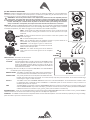
MAINS IN - Powercon® NAC3FCA power input connector (blue). To switch the amplifier on, insert the Powercon®
connector and turn it clockwise into the ON posi on. To switch the amplifier off, pull back the switch on the
connector and turn it counter-clockwise into the POWER OFF posi on.
WARNING! In the case of product failure or fuse replacement, disconnect the unit completely from the
mains power. The power cable must only be connected to a socket corresponding to the specificaƟons
indicated on the amplifier unit. The power supply must be protected by a suitably rated thermo-magneƟc
breaker. Preferably use a suitable switch to power on the whole audio system leaving the Powercon®
always connected to each speaker, this simple trick extend the life of the Powercon® connectors.
LOCK
MAINS OUT
MAINS OUT - Powercon® NAC3FCB power output connector (grey). This is connected in parallel with the MAINS
~ / IN. The maximum load applicable depends on the mains voltage. With 230V~ we suggest to link a maximum
of 4 CX15A loudspeakers, with 120V~ we suggest to link a maximum of 2 CX15A loudspeaker.
PUSH
OFF
INPUT - Audio signal input with locking XLR connector. It has a fully electronically
balanced circuitry including AD conversion for the best S/N ratio and input
headroom.
LINK - A direct connec on from the input connector to link other speakers with
INPUT same audio signal.
ON
ON - This LED indicates power on status.
module.
T
ER
CU
W
US
D
UP
LE
LO
GND LIFT - This switch li the ground of the balanced
LINK audio inputs from the earth-ground of the amplifier
CO
NO
RM
AL
W
ED
GE
SIGN/LIMIT - This LED lights in green to indicate the
presence of the signal and lights in red when an internal
limiter reduces the input level.
UN
IT
S
MAINS~ IN
PROT - This red LED lights when the amplifier module is in protect mode for an
internal fault and, consequently, the amplifier is muted.
ON
PROT
SIGN/LIMIT
PRESET BUTTON - This bu on has two func on:
1) Pressing it while powering on the unit:
ID ASSIGN
the internal DSP assigns a new ID to the unit for the PRONET remote
control opera on. Each loudspeaker must have a unique ID to be
visible in the PRONET network. When you assign a new ID, all the
other loudspeakers with the ID already assigned must be ON and
connected to the network.
2) Pressing it with the unit ON you can select the DSP PRESET. The selected PRESET
is indicated by the corresponding LED:
NORMAL WEDGE This PRESET is suitable for typical stage monitor applica ons. It
can be used also when the CX15A is used mounted on a pole.
TERMINATE
IN
NETWORK
OUT
COUPLED UNITS
This preset provides the correct EQ when two CX15A monitors,
fed with the same audio signal, are placed at no more than 0,6 m (2 feet) one to the other. To be used for double stage
monitoring for singers or other musicians.
LOW CUT
This PRESET is the same as NORMAL WEDGE but with a low cut at 110 Hz 48 dB/oct. To be selected when a CX15A is used
in combina on with a subwoofer to form a DRUM FILL or a SIDE FILL system. It can be used also in case you need to cut
dras cally the monitor LF response.
USER
The USER PRESET corresponds to the first USER MEMORY (Preset 4-U) stored in the DSP and, as a factory se ng, it’s the
same as NORMAL WEDGE. If you want to modify it, you have to connect the unit to a PC, edit the parameters with PRONET
so ware and save it into “Preset 4-U-your_preset_name” (see also further in this manual).
NETWORK IN/OUT - These are a standard RJ45 CAT5 connectors (with op onal NEUTRIK NE8MC RJ45 cable connector carrier), used for PRONET
network transmission of remote control data over long distance or mul ple unit applica ons.
TERMINATE - In a PRONET network the last loudspeaker device must be terminated (with an inner load resistance) especially in a long run cabling:
press this switch if you want to terminate the unit.