1
Section 7
Operation
A SUPPLEMENT to the OPERATION MANUAL FOR THE
CINCINNATI CL-800 Series
Laser System
Edited for CINCINNATI Laser Control Software Version 8.2
C I N C I N N AT I I N C O R P O R AT E D
C I N C I N N A T I, OHIO 4 5 2 1 1
CINCINNATIR
EM-544 (R-07/10)
COPYRIGHT 2010
CINCINNATI INCORPORATED
SECTION
title
SECTION X
7:: operation
CONTENTS
CONTENTS
INTRODUCTION
HMI Overview
Laser System Display window............................................................7-1
MENU BAR...............................................................................................7-2
TOOL BAR................................................................................................7-2
STATUS INDICATORS CONTROL BAR...................................................7-3
PROCESS STATUS BAR..........................................................................7-3
APPLICATION WORKSPACE...................................................................7-3
OPERATOR CONSOLE CONTROL BAR.................................................7-3
PROGRAM MODES CONTROL BAR.......................................................7-4
PROGRAM STATUS BAR.........................................................................7-4
MAIN STATUS BAR..................................................................................7-4
File Types....................................................................................................7-4
NC PROGRAM FILE.................................................................................7-5
PROCESS PARAMETER FILE.................................................................7-5
BATCH PROGRAM FILE..........................................................................7-6
CNC Run Window.......................................................................................7-7
CONTROL bars
Operator Console..................................................................................7-9
RESONATOR CONTROLS.......................................................................7-9
OVERRIDE SETTINGS...........................................................................7-10
OPERATING MODES............................................................................. 7-11
Override Adjust ....................................................................................7-12
Auxiliary Functions..............................................................................7-13
Program Modes......................................................................................7-14
PROGRAM TEST MODE........................................................................7-14
REWIND..................................................................................................7-14
BLOCK DELETE MODE.........................................................................7-15
OPTIONAL STOP MODE........................................................................7-15
SINGLE BLOCK MODE..........................................................................7-15
TRACE MODE........................................................................................7-15
Menu Commands
File Menu...................................................................................................7-17
NEW........................................................................................................7-17
OPEN......................................................................................................7-17
QUICK FILE OPEN.................................................................................7-19
OPEN LOADED PROGRAM...................................................................7-19
OPEN CURRENT PROCESS.................................................................7-19
CLOSE....................................................................................................7-20
SAVE.......................................................................................................7-20
SAVE AS..................................................................................................7-20
LOAD NC PROGRAM.............................................................................7-21
LOAD CURRENT PROGRAM.................................................................7-22
LOAD CURRENT BATCH.......................................................................7-22
PLOT NC PROGRAMS...........................................................................7-22
RESTART LOADED PROGRAM.............................................................7-24
PRINT......................................................................................................7-25
PRINT PREVIEW....................................................................................7-25
PRINT SETUP.........................................................................................7-26
MRU FILE LIST.......................................................................................7-26
OPEN OPERATOR LOG.........................................................................7-27
EXIT.........................................................................................................7-27
EM-544 (R-07/10)
Edit Menu...................................................................................................7-27
UNDO…..................................................................................................7-27
CUT.........................................................................................................7-27
COPY......................................................................................................7-28
PASTE.....................................................................................................7-28
FIND........................................................................................................7-28
REPLACE................................................................................................7-28
View Menu..................................................................................................7-29
CONTROL BAR.......................................................................................7-29
LANGUAGE............................................................................................7-30
UNITS......................................................................................................7-30
ALARMS AND MESSAGES WINDOW...................................................7-31
AXES POSITIONS..................................................................................7-32
MODAL G CODES..................................................................................7-32
ALL POSITION INFORMATION..............................................................7-32
RUN WINDOW GRAPHICS....................................................................7-33
WINDOW ZOOMING...............................................................................7-33
Maintenance Menu.................................................................................7-34
CONFIGURATION...................................................................................7-34
MIRROR ALIGNMENT............................................................................7-44
DIAGNOSTICS........................................................................................7-45
RESONATOR..........................................................................................7-48
STATISTICS............................................................................................7-51
Laser Menu...............................................................................................7-52
LASER STATUS MONITOR....................................................................7-52
AUTO START-UP....................................................................................7-54
AUTO SHUT-DOWN...............................................................................7-55
RESONATOR SET-UP WINDOW...........................................................7-56
Variables Menu.......................................................................................7-57
LOCAL/GLOBAL VARIABLES.................................................................7-57
USER I/O VARIABLES............................................................................7-57
WORK OFFSETS....................................................................................7-58
MACHINE OFFSETS..............................................................................7-58
Utilities Menu..........................................................................................7-59
STANDOFF CALIBRATION.....................................................................7-59
OPERATOR SETUP................................................................................7-59
LENS CENTERING.................................................................................7-63
SPEED GAS............................................................................................7-64
Window Menu...........................................................................................7-64
CASCADE...............................................................................................7-64
TILE.........................................................................................................7-64
ARRANGE ICONS..................................................................................7-64
WINDOW 1, 2 .........................................................................................7-65
Help Menu..................................................................................................7-65
TOPICS...................................................................................................7-65
MANUALS...............................................................................................7-65
ABOUT CINCINNATI LASER SYSTEM..................................................7-66
Cutting Process Parameters
Introduction...........................................................................................7-67
Process Parameter Window.............................................................7-67
PIERCE PARAMETERS..........................................................................7-68
RAMPED PIERCE PARAMETERS.........................................................7-69
RAPID PIERCE PARAMETERS..............................................................7-70
CUT PARAMETERS................................................................................7-71
DYNAMIC POWER CONTROL PARAMETERS.....................................7-72
FOCUS PARAMETERS..........................................................................7-74
PROCESS PARAMETER NOTES..........................................................7-75
Process Monitor...................................................................................7-76
PIERCE-THROUGH DETECTION..........................................................7-76
ADAPTIVE PIERCE MODE....................................................................7-78
LOSS OF CUT DETECTION...................................................................7-79
EM-544 (R-07/10)
Start-up and Shut-down
Laser System Start-up.........................................................................7-81
Chiller Warm-up.....................................................................................7-83
Shutting Down the Laser System...................................................7-83
Calibration and Adjustment Procedures
Nozzle Standoff Calibration............................................................7-85
NONCONTACT STANDOFF SENSING .................................................7-85
Laser Shot................................................................................................7-86
SETUP FOR A LASER SHOT.................................................................7-86
TAKING A LASER SHOT.........................................................................7-87
Centering the Focusing Lens...........................................................7-87
LENS CENTERING PROCEDURE.........................................................7-88
Lens Focal Point Location.................................................................7-91
FOCUS CALIBRATION - AUTO FOCUS HEAD . ...................................7-92
Assist Gas Pressure Adjustment...................................................7-93
Rapid Pierce Adjustments..................................................................7-94
Cutting Procedures
First Run of Parts.................................................................................7-95
Error Recovery....................................................................................7-97
CUTTING HEAD BREAKAWAY..............................................................7-97
RESTARTING A PROGRAM...................................................................7-97
Batch mode Program Execution.....................................................7-98
Machine Setup Checking.....................................................................7-99
Auto Focus Cutting Head
Focus Control System Configuration.......................................7-103
Auto Focus Setup................................................................................7-104
FOCUS CONTROL SYSTEM HOME OFFSETS..................................7-104
FOCUS SETUP FOR LENS CENTERING . .........................................7-104
Focus-Related Process Parameters..........................................7-105
Auto Focus Operation.......................................................................7-106
HOMING THE FOCUS CONTROL SYSTEM........................................7-106
Windows Administration
Manager Account................................................................................7-109
LASER UTILITIES FOLDER................................................................. 7-110
SOFTWARE INSTALLATION AND UPGRADES................................... 7-110
Setup Account...................................................................................... 7-111
SOFTWARE INSTALLATION AND UPGRADES................................... 7-112
EMERGENCY REPAIR DISK................................................................ 7-112
NETWORK SETUP............................................................................... 7-112
JOINING A DOMAIN............................................................................. 7-112
Drive Designations.............................................................................. 7-112
MAPPING NETWORK DRIVES............................................................ 7-113
Backing up THE control.................................................................... 7-113
Multiple Operator User Accounts.............................................. 7-113
Touchscreen Calibration................................................................ 7-113
Alarms and Messages
Operator FYI Messages..................................................................... 7-115
System Alarms...................................................................................... 7-118
Program Errors..................................................................................7-125
Laser Alarms.........................................................................................7-128
Troubleshooting................................................................................7-129
EM-544 (R-07/10)
Laser NC Programming
Standard G Codes...............................................................................7-131
G00 RAPID TRAVERSE MOVE............................................................7-131
G01 LINEAR MOVE..............................................................................7-132
G02 AND G03 ARC MOVE...................................................................7-132
G04 DWELL..........................................................................................7-134
G09 EXACT STOP (ONE BLOCK)........................................................7-135
G20 INCH MODE, G21 METRIC MODE...............................................7-135
G31 POSITION CAPTURE MOVE........................................................7-135
G40, G41, AND G42 KERF COMPENSATION.....................................7-135
G50 AND G51 COORDINATE SYSTEM SCALING..............................7-137
G52 LOCAL WORK COORDINATE SYSTEM......................................7-138
G53 RAPID MOVE TO MACHINE COORDINATES.............................7-138
G54…G59 WORK COORDINATE SYSTEM SELECTION ..................7-139
G61 AND G64 EXACT STOP MODE....................................................7-139
G65 SUB-PROGRAM CALL . ...............................................................7-139
G68 WORK COORDINATE ROTATION................................................7-139
G90 AND G91 ABSOLUTE AND INCREMENTAL MODE.....................7-140
G92 WORK COORDINATE SYSTEM SETTING..................................7-140
Custom G Codes...................................................................................7-141
G84 AND G85 START CUTTING SEQUENCE.....................................7-141
G89 SET PROCESS PARAMETERS....................................................7-143
G102 SET ADDITIONAL PROCESS PARAMETERS...........................7-145
G103 SET RAMPED PIERCE PARAMETERS.....................................7-145
G120 AND G121 NON-STOP CUTTING...............................................7-146
G123, G124, AND G125 VELOCITY BLENDING..................................7-148
M Codes....................................................................................................7-150
M00 PROGRAM STOP.........................................................................7-150
M01 OPTIONAL STOP..........................................................................7-150
M02 END OF PROGRAM.....................................................................7-150
M30 END OF PROGRAM / REWIND....................................................7-150
M35 BEAM OFF....................................................................................7-150
M36 Z HOLD MODE.............................................................................7-150
M37 BEAM AND GAS OFF / SHUTTER CLOSE..................................7-151
M38 Z HOLD MODE (TIMED)...............................................................7-151
M41 Z DOWN........................................................................................7-151
M42 Z UP..............................................................................................7-151
M43 LOWER PALLET SPECIAL FUNCTION ......................................7-151
M44 DISABLE LOWER PALLET SPECIAL FUNCTION ......................7-152
M45 OPTIONAL STANDOFF MODE....................................................7-153
M47 PARTIAL Z UP . ............................................................................7-153
M48 FEEDRATE OVERRIDE DISABLE ..............................................7-153
M49 FEEDRATE OVERRIDE ENABLE.................................................7-153
M50 SWITCH PALLETS........................................................................7-154
M51 AUXILIARY OUTPUT (TIMED)......................................................7-154
M67 OPTIONAL ASSIST GAS PRESSURE.........................................7-154
M90 BALL TRANSFER UP....................................................................7-154
M91 BALL TRANSFER DOWN.............................................................7-154
M98 SUBPROGRAM CALL...................................................................7-155
M99 END SUBPROGRAM....................................................................7-155
M130 AND M131 Z-AXIS ANTIDIVE.....................................................7-155
M135 SPEED GAS BEAM OFF............................................................7-156
M151 AUXILIARY OUTPUT WITH CONFIRMATION............................7-156
CINCINNATI Macros...............................................................................7-157
GRID MACROS.....................................................................................7-157
Cutting Macros....................................................................................7-160
G73 HOLE MACRO..............................................................................7-160
G76 SLOT MACRO...............................................................................7-161
G79 LINE MACRO................................................................................7-161
G83 OUTSIDE CIRCLE MACRO..........................................................7-162
G86 OUTSIDE RECTANGLE MACRO..................................................7-162
G88 BOLT CIRCLE MACRO.................................................................7-163
G104 SHAPE MACRO..........................................................................7-163
M2 LEAD-IN DESCRIPTION.................................................................7-165
G105 LEAD-IN MACRO........................................................................7-166
EM-544 (R-07/10)
Program Structure...........................................................................7-167
PROGRAM NAME................................................................................7-167
PROGRAM BODY.................................................................................7-167
BEAM ON AND OFF COMMANDS.......................................................7-168
PROGRAM COMMENTS......................................................................7-168
PROGRAM LINE NUMBERS................................................................7-168
BLOCK DELETE...................................................................................7-168
END OF PROGRAM.............................................................................7-169
SUBPROGRAMS AND MACROS.........................................................7-169
LOCAL VARIABLES..............................................................................7-169
NESTED SUB-PROGRAM CALLS.......................................................7-171
Program Variables.............................................................................7-171
LOCAL AND COMMON VARIABLES....................................................7-171
SYSTEM VARIABLES...........................................................................7-172
Auxiliary Functions............................................................................7-175
MATH FUNCTIONS...............................................................................7-175
LOGIC FUNCTIONS.............................................................................7-176
AUXILIARY COMMANDS.....................................................................7-178
WORKPIECE EDGE DETECTION.......................................................7-180
NC Code List...........................................................................................7-189
M CODE LIST........................................................................................7-189
G CODE LIST........................................................................................7-190
EM-544 (R-07/10)
EM-544 (R-07/10)
CINCINNATI LASER SYSTEM SECTION 7
CINCINNATI CL-800 SERIES LASER SYSTEM
Supplement Manual - Section 7, Operation - for CL-800 Models
This manual applies to all CL-800 Series Laser Systems with resonators, including all frame sizes and resonator
wattages.
Control Software Versions
This document was last updated for compatibility with the following control software:
CNC/HMI software - 845601
Version 8.2
- 845759
Version16
PLC software
Laser System Help Version: 1.4
EM-544 (R-07/10)
EM-544 (R-07/10)
HMI Overview
The Human Machine Interface (HMI) is the means provided for interacting with the laser system control. The HMI tools
consist of the Operator Control Station front panel and side panel pushbutton controls, the LCD monitor/touchscreen, the
trackball pointing device, the keyboard, the remote station, and the Laser System CNC/HMI software. The pushbutton
controls and remote station functions are described in SECTION 6 - MACHINE CONTROLS of the Laser System
Operation, Safety, and Maintenance Manual.
This chapter presents an overview of the software user interface. The touchscreen, trackball, and keyboard can be used to
navigate around the user interface. The foundation of the software user interface is the Laser System Display window.
Laser System Display window
The Laser System Display window occupies the entire display screen on the operator control station. The main components
of the Laser System Display window are the Title Bar, Menu Bar, Tool Bar, Status Indicators Control Bar, Application
Workspace, Operator Console Control Bar, and Main Status Bar. A Process Status Bar, Program Modes Control Bar, and
Program Status Bar may also be visible, depending on the current operating mode of the Laser System.
7-1
EM-544 (R-07/10)
MENU BAR
The Menu Bar is the row of main menu titles across the top of the Laser System Display window. Selecting a menu title
opens a pop-up menu displaying a list of menu commands. See the MENU COMMANDS section for a description of each
command.
TOOL BAR
The Tool Bar, located below the Menu Bar, contains a row of buttons where each button corresponds to a menu command.
The Tool Bar provides convenient, single-touch access to some of the more commonly used menu commands. The Tool
Bar can be hidden or displayed by going to: View | Control Bars.
This list identifies which menu command is associated with each Tool Bar button:
File | New
File | Open
File | Save
File | Load Current Program
File | Open Loaded Program
File | View Current Process
View | View Axes Positions
Utilities | Operator Setup
Utilities | Lens Centering Mode
Utilities | Standoff Calibration
Open the CINCINNATI Laser Programming and Nesting application, if installed.
EM-544 (R-07/10)
7-2
STATUS INDICATORS CONTROL BAR
The Status Indicators Control Bar, which is normally positioned to the right of the Tool Bar, consists of separate indicators
for resonator state: “alarm condition present” and “operator message ready”. The left-most indicator shows the current
resonator operating state. Click or touch this indicator for a shortcut to open the Laser Status Monitor window. The “Alarm”
indicator signifies the presence of system alarms or resonator alarms when its color is red. A flashing red indicator means
that one or system alarms are active. A solid red indicator means that only resonator alarms are active. A yellow “Message”
indicator signifies that one or more operator FYI messages are pending. Both the “Alarm” and “Message” indicators can be
used as shortcut buttons to open or close the Alarms and Messages window. The status indicators can be used as a shortcut
to open or close the Laser Status Monitor window.
PROCESS STATUS BAR
The Process Status Bar, which is located below the Tool Bar, displays critical process information such as feedrate, laser
power, beam focus position, assist gas pressure, and nozzle standoff. The Process Status Bar is only displayed when the
Laser System is in Auto mode. All displayed values are updated in real time. While the control is in Auto mode, the Process
Status Bar can be hidden or displayed by going to View | Control Bars | Process Status Bar.
APPLICATION WORKSPACE
The Application Workspace is the area (initially blank) which is below the Process Status Bar or Tool Bar and above the
Program Status Bar. NC program windows, Process Parameter windows, and all other user-activated windows and dialogs
will open in this area.
OPERATOR CONSOLE CONTROL BAR
The Operator Console Control Bar contains the user interface controls used by the machine operator to control and monitor
the basic operating mode of the Laser System. See OPERATOR CONSOLE in the CONTROL BARS section, for
information on this control bar.
7-3
EM-544 (R-07/10)
PROGRAM MODES CONTROL BAR
The Program Modes Control Bar is used to manage the various program execution modes that affect how the control
software executes NC programs. Like the Process Status Bar, the Program Modes Control Bar is only visible when the Laser
System is in Auto mode. See PROGRAM MODES in the CONTROL BARS section for more on program modes.
PROGRAM STATUS BAR
The Program Status Bar, located just below the Application Workspace, displays the cutting program execution status. Like
the Program Modes Control Bar and the Process Status Bar, this status bar is visible only when the control is in Auto mode.
The Program Status Bar is divided into two fields, the left field contains the file name of the currently loaded NC program.
This field is empty when there is no NC program loaded into the control. The right field indicates the current state of the
program execution subsystem. For example: “Program not loaded”, “Executing”, or “Program Stopped” may be displayed
here.
MAIN STATUS BAR
The Main Status Bar is displayed at the bottom of the Laser Status Monitor window, and is used to display operator help
messages and other general information. The Main Status Bar is divided into several sections. The section to the right of
the CINCINNATI logo displays a brief description of Menu Bar and Tool Bar button commands as these items are selected
with the trackball or keyboard.
To the right of the command description is the laser control system “heartbeat” indicator. A properly functioning control
system is indicated by two alternately flashing green indicators. If either indicator stops flashing or turns red, power down
the system and restart it. If this does not return the indicators to their proper state, contact CINCINNATI INCORPORATED
Laser Service Department.
The next field to the right is the NC Program file line number of the line where the cursor is currently located. This field is
blank if an NC Program Edit window is not the currently active window.
In the far right section of the Main Status Bar, the current time is displayed.
File Types
The Laser System control software gets the information it needs to execute cutting applications from two types of data files:
NC Program files and Process Parameter files. A third type of file, the Batch Program file, may be used if desired, to create
a list of NC Program files to be executed in the specified order.
EM-544 (R-07/10)
7-4
The File menu commands and Tool Bar buttons, described later, can be used to open these files for viewing/editing, and to
create new files. When opening an existing file or creating a new file, a window will appear in the Application Workspace,
displaying the file’s contents. The Title Bar of each file view window contains the name of its file.
When a file is modified, it must be saved using File | Save or Tool Bar Save command before any changes will take effect.
An asterisk “*” will appear next to the file name of any file that has been modified but not saved.
The following topics describe each of the three types of file and their view windows.
NC PROGRAM FILE
The NC Program file contains the NC codes that determine the part feature geometry and control the various machine
cutting functions. NC programs, which may be as simple as a single part or as complex as multiple sheets of nested parts,
are typically generated by nesting/post-processing software packages such as the CINCINNATI Laser Programming
and Nesting Software application. NC Program file names should end with “.cnc” (ex: “Filename.cnc”).
When an NC Program file is opened, its contents are displayed in a Program Edit window. Program Edit windows use
context coloring; distinct program components are displayed with different colors (G codes are blue, M codes are red,
etc).
PROCESS PARAMETER FILE
The Process Parameter file contains settings used to control the power and focusing attributes of the laser beam and the
cutting assist gas. Process Parameters are stored in multiple files, with a separate file for each distinct cutting process. All
CINCINNATI Laser Systems are shipped with a library of Process Parameter files containing the cutting parameter settings
recommended by CINCINNATI INCORPORATED. These files are stored in the “Cnclsr32/Material” folder on the laser
control’s computer hard disk drive. These files can be modified to specify other cutting processes by creating new Process
Parameter files with the preferred settings. Process Parameter file names should end with “.lib” (ex: “Filename.lib”).
G89 blocks in the NC Program file specify which Process Parameter file(s) will be used in each cutting application. See
CUSTOM G CODES in the LASER NC PROGRAMMING topic for more information on G89.
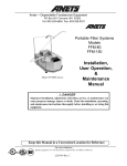
When a Process Parameter file is opened, the parameter settings are displayed in a Process Parameter window, shown on
next page. See the CUTTING PROCESS PARAMETERS topic for more information on process parameters.
Note: An “Active” or “Loaded” indicator:
may be displayed in the upper right corner of the Process
Parameter window. If a Process Parameter file that is loaded via a G89 block anywhere in the active NC program
is open in a window, a yellow “Loaded” indicator will be displayed. If this file represents the currently active
cutting process, then an orange “Active” indicator will be displayed.
7-5
EM-544 (R-07/10)
BATCH PROGRAM FILE
A Batch Program file is a list of NC Program files that will be loaded and executed in the order listed. It allows programs
to be grouped together in a logical manner and allows the control to keep track of which programs have been completed
and which program to load next. A Batch Program can contain up to one hundred program entries and each entry can be
repeated up to one hundred times. Batch Program file names should end with “.bch” (ex: “Filename.bch”).
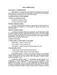
When a Batch Program file is opened, the parameter settings are displayed in a Batch Program window:
Creating a Batch Program
To create a new Batch Program:
1. Select File | New and then select “Batch” file type in the New Selection window. Click “OK” to close the New Selection
window.
2. In the new Batch Program window, select the “New Entry”
programs that will be added to the batch.
button until the window has enough rows for all NC
3. In each row, enter the NC Program file name in the Program column by typing it directly or using the “Browse”
button to select it with the trackball.
4. Enter the number of times that each program will run in the Repeat column by typing it directly or by using the arrow
buttons
.
5. If it becomes necessary to move or delete an entire row, select the row using the “Row Select”
the “Move Up”
EM-544 (R-07/10)
, “Move Down”
, or “Delete Entry”
7-6
button.
button and then press
Editing a Batch Program
Batch Program editing functions are provided in the Batch Program window. The editing functions are:
Insert new row Inserts a new NC Program file entry after the selected entry or at the end of the list.
Copy a row Copies the selected row and inserts the copy into the list after the selected row.
Delete Entry
Deletes the selected entry.
Move Up
Moves the selected entry up one row in the list.
Move Down
Moves the selected entry down one row in the list.
Stop the Batch Stops a running Batch Program.
CNC Run Window
The CNC Run Window displays the execution status of the active cutting program, if a program is currently loaded. This
window cannot be manually opened or closed. The control software will automatically display the CNC Run Window
each time a part program is successfully loaded, and whenever the control enters Auto mode while a program is loaded.
Likewise, the CNC Run Window will automatically close whenever the control enters Jog mode or Axes Home mode.
The CNC Run Window has two sections and a status bar. The left section displays the NC program code with the active
block highlighted. To help locate the current position in an interrupted cutting program, the active subroutine name and
line number are displayed in a green box at the top of the NC code section. All currently active subroutines are displayed,
indented to the right to indicate the nesting depth for nested subroutines.
The right section is a graphical plot of the current sheet program. For each sheet, the status bar at the bottom of the window
displays the sheet number, the remaining runtime, and a bar graph showing the percentage of completed program blocks.
The plotting software interprets M50 as the start of another sheet.
Before the program starts each sheet, the plot shows all X-axis and Y-axis rapid moves in green. Contouring moves with the
laser beam on are shown in blue. Contouring moves with the laser beam off are shown in yellow. As the program runs, the
plot changes the color of all completed moves to red. To change the width of the plot section, select the divider between the
left and right sections and drag it to another location. To change the viewing area of the plot, use any of the various Zoom
features. See WINDOW ZOOMING in the VIEW MENU section.
If desired, the plot section and status bar can be hidden, resulting in a much smaller CNC Run Window. See RUN WINDOW
GRAPHICS in the VIEW MENU section.
7-7
EM-544 (R-07/10)
EM-544 (R-07/10)
7-8
CONTROL bars
Operator Console
The Operator Console Control Bar contains three different groups of user controls: Laser Resonator, Override Settings, and
Operating Mode. There are also two buttons that can be used to quickly open or close other control bars.
Selecting the “Aux.” button will open the Auxiliary Functions Control Bar if it is not currently open, or close it if it is
currently open. Selecting the “Override Adjust” button will open the Override Adjust Control Bar if it is not currently open,
or close it if it is currently open.
RESONATOR CONTROLS
This part of the Operator Console Control Bar contains controls related to the laser resonator.
Laser Mains: This control is both a button and indicator for the resonator Mains. Laser Mains will appear bright green (ON)
when resonator Mains is on, and dull green or gray (OFF) when Mains is off. The “Laser Mains” button commands the
main contactor of the laser resonator to open or close. The contactor supplies electrical power to the solenoids, vacuum
pump, fans, and alignment laser in the resonator.
Selecting this button when Mains is off commands the contactor to close, initiating the resonator Mains startup sequence.
During the startup sequence, the indicator blinks on and off; when the startup sequence is complete, the indicator will
remain on. When Mains is on and laser High Voltage is off, pressing the “Laser Mains” button commands the contactor
to open, turning Laser Mains off.
Note: Laser Mains cannot be turned off when High Voltage is on. This feature prevents accidental deactivation if the
touchscreen is bumped.
7-9
EM-544 (R-07/10)
High Voltage: The “High Voltage” button/indicator will appear bright green (ON) when resonator High Voltage is on, and
dull green or gray (OFF) when High Voltage is off. If the “HIGH VOLTAGE” keyswitch on the Machine Operator Side
Panel is in the LOCKED position, the indicator will be appear off, displaying an image of a padlock.
The “HIGH VOLTAGE” button commands the control to connect or disconnect electrical power to the resonator high
voltage power supply. High Voltage will not activate unless Laser Mains is on, no interlock faults are present, and the
“HIGH VOLTAGE” keyswitch is in the “ENABLED” position.
Selecting this button when High Voltage is off commands the control to connect power to the high voltage power supply,
initiating the High Voltage startup sequence. During the startup sequence, the indicator blinks on and off; when the
startup sequence is complete, the indicator will remain on. Selecting this button when High Voltage is on commands the
control to remove electrical power from the resonator high voltage power supply.
Laser Beam: This indicator displays the On/Off status of the laser beam. The “Laser Beam” indicator is red (ON) when
laser discharge current indicates that the resonator is producing a laser beam. The resonator produces a laser beam in
response to requests for laser power. Laser power can be requested by the program by the Mirror Alignment or Lens
Centering function or by the Maintenance function for Manual Power Control. When the resonator is not producing a
laser beam, the indicator color is dull red or gray (OFF).
Shutter: This indicator displays the shutter state. When the “SHUTTER” keyswitch on the Machine Operator Side Panel is
in the “ENABLED” position, the indicator color depends on the position of the shutter within the laser resonator cabinet:
the “Shutter” indicator will appear red (OPEN) if the shutter is completely open, and dull red or gray (CLOSED), if the
shutter is completely closed. When the “SHUTTER” keyswitch is in the “LOCK/CLOSE” position, the indicator will
be appear closed, displaying an image of a padlock.
With the shutter completely closed, the laser beam is contained within the laser resonator cabinet and is not present in
the beam delivery system. With the shutter open, the laser beam can be guided through the beam delivery system to the
workpiece.
Note: When the shutter is open, the Laser System control changes the color of the “Shutter” button to red and
illuminates the red light on top of the gantry or the safety enclosure.
The “Shutter” button provides manual control of the shutter only when High Voltage is off and the “SHUTTER”
keyswitch is in the “ENABLED” position. Under these conditions, the shutter can be manually opened or closed by
selecting the gray “Shutter” button. When the shutter is manually opened, it will remain open after the indicator is
selected. To close the shutter, select the “Shutter” indicator again, or turn the “SHUTTER” keyswitch to the “LOCK/
CLOSE” position.
OVERRIDE SETTINGS
In the center section of the Operator Console Control Bar, the current values of the Jog/Feedrate and Assist Gas Override
settings are displayed.
It is easy to change either override setting by selecting one of the override display boxes. This will cause the Override
Adjust Control Bar to open. Once selected, that display box will change to a red text/yellow background color to indicate
that the corresponding override is activated for adjustment in the Override Adjust Control Bar.
EM-544 (R-07/10)
7-10
OPERATING MODES
The bottom section of the Operator Console Control Bar contains three button/indicator controls for the primary operating
mode, and an “Alternate Mode” indicator.
Jog: This button/indicator activates Jog mode. While the control is in Jog mode, the “Jog” indicator color is amber. In
Jog mode, the axis motion controls on the Operator Control Station front panel or the Remote Station can be used to
manually move (“jog”) each machine axis individually. Cutting program execution is disabled while Jog mode is active.
Most Maint. | Utilities functions, such as Lens Centering, are only enabled when the Laser System is in Jog mode. The
control will remain in Jog mode until another mode is selected.
Auto: This button/indicator activates Auto mode. The Laser System must be in Auto mode in order to run cutting programs.
While the control is in Auto mode, the “Auto” indicator color is amber, and most Maint. | Utilities functions, are
disabled. The NC Program files and Process Parameter Files while the control is executing a program in Auto mode. The
control will remain in Auto mode until another mode is selected.
Axes Home: This button/indicator activates Axes Home mode. When selected, the “Axes Home” button text changes to
“Homing” and the color changes to amber. To home the axes, the main drives must be on with no system alarms present.
The Axes Homing function begins when the operator presses the “CYCLE START” pushbutton. When all axes have
moved to their reference positions, all axis motion stops, the Axes Home function ends and the control automatically
changes to Jog mode.
Special Operating Mode
Special Operating Modes are alternate modes the Laser System is in while certain functions are active:
•
Lens Centering
•
Standoff Calibration
•
Mirror Alignment
•
Manual Beam Control
Note: The Laser System must be in Jog mode before a “Special Operating Mode” can be activated.
Special operating modes are typically modes in which the “CYCLE START” / “CYCLE STOP” buttons perform some
unique function other than starting the execution of a cutting program. For example, Standoff Calibration is a “Special
Operating Mode” since “CYCLE START” initiates the Noncontact Head standoff calibration sequence. When any of these
special operating modes are active, the amber-colored “Alternate Modes” indicator will be visible, and the three primary
operating mode buttons will be disabled.
7-11
EM-544 (R-07/10)
Override Adjust
The Override Adjust Control Bar contains a slider control can be used to adjust the setting of either the Jog/Feedrate
Override or the Assist Gas Override function. Only one override setting, the active override, is adjusted at a time. The
active override is selected by selecting either the “Jog/Feedrate” or the “Assist Gas” button. The currently active override
is indicated by a green check mark on the corresponding button and a yellow background color for the “Override Settings”
indicator in the Operator Console Control Bar.
The Override Adjust Control Bar can be opened/closed in any of the following ways:
•
Select the “Override Adjust” button in the Operator Console Control Bar.
▪ Select either “Override Settings” indicator in the Operator Console Control Bar; this will also make the corresponding
override active.
•
Go to: View | Control Bars | Overrides
There are several ways to change the slider control setting in the Override Adjust Control Bar:
•
After selecting the slider control, the “Page Up” and “Page Down” keyboard keys will change the setting in 5%
increments.
•
The “Up Arrow” and “Down Arrow” keyboard keys change the setting in 1% increments.
•
Select the “Slider Control” indicator with the trackball pointing device and then drag it to any setting.
•
Rotate the wheel on the trackball pointing device after selecting the slider control.
Assist Gas Override: This setting modifies the programmed assist gas pressure used for cutting. For example, if the program
specifies 200 PSI and the assist gas override is set to 75%, the actual cutting pressure will be: 75% of 200 PSI = 150 PSI.
This setting also affects the pressure achieved when assist gas is manually activated using one of the assist gas buttons
on the Auxiliary Functions Control Bar. The assist gas override setting is adjustable from 0% to 150%.
Note: The Assist Gas Override setting does not affect the assist gas pressure used when piercing.
Jog/Feedrate Override: When the NC cutting program commands the X-axis and/or Y-axis to a position with a G01,
G02, or G03 block, the actual feedrate will be the percentage of the commanded feedrate specified by the Jog/Feedrate
Override setting. For example, if Jog/Feedrate Override is set to 75% and the program specifies “F400”, the actual
feedrate will be 75% of 400 IPM = 300 IPM. The Jog/Feedrate Override setting is adjustable from 0% to 100%. The
Feedrate Override is disabled during rapid moves (G0) or when M48 is active.
Jog/Feedrate Override also changes the jogging speed of the X- and Y-axes when the “RAPID TRAVERSE” button
is not lit. The jogging speed at 100% is the “X/Y-axis Jog Speed” specified on the General page of the Maintenance/
Machine Configuration window (300 IPM or 7620 mm/min typical).
EM-544 (R-07/10)
7-12
Auxiliary Functions
The Auxiliary Functions Control Bar contains buttons for manually activating assist gas flow and the fume blower system.
Open/close this control bar by selecting the “Aux.” button on the Operator Console Control Bar, or by selecting View |
Control Bars | Aux.
Oxygen: This control is both a manual activation button and indicator for oxygen assist gas. When executing a cutting
program, the control automatically commands assist gas flow through the nozzle. When oxygen assist gas is flowing,
the “Oxygen” indicator color changes from dull green or gray (OFF) to bright green (ON). This button is used in Jog or
Auto mode to manually control the oxygen assist gas solenoid valve.
Nitrogen: This control is both a manual activation button and indicator for nitrogen assist gas. When nitrogen assist gas is
flowing, the “Nitrogen” indicator color changes from dull green or gray (OFF) to bright green (ON). This button is used
in Jog or Auto mode to manually control the nitrogen assist gas solenoid valve.
Air: This control is both a manual activation button and indicator for air assist gas. When air assist gas is flowing, the “Air”
indicator color changes from dull green or gray (OFF) to bright green (ON). This button is used in Jog or Auto mode to
manually control the air assist gas solenoid valve.
Note: Only one assist gas can be active at a time. If nitrogen is flowing when the oxygen button is selected, the nitrogen
gas solenoid will close and the oxygen gas solenoid will open, etc.
Fume Blower: This a manual activation button and indicator for the fume blower. Selecting this button toggles the fume
blower on or off when the program is not running. The fume blower turns on automatically when the machine is cutting.
When the program ends, the fume blower remains on for 60 seconds, plus the Blower OFF delay time specified on the
Auxiliary page of the Configuration window, and then turns off automatically. This button is used to provide additional
fume removal time. The “Fume Blower” indicator color is dull green or gray (OFF) when the fume blower is off and
bright green (ON) when the fume blower is running.
7-13
EM-544 (R-07/10)
Program Modes
The Program Modes Control Bar contains controls that turn on or off the various program execution modes that affect how
the control software executes NC programs. Each control is both a button and indicator for the corresponding mode. Like
the button/indicators in the other control bars, these controls appear bright green (ON) when the corresponding mode is
active, and dull green or gray (OFF) when the mode is not active.
The Laser Control Software automatically displays the Program Modes Control Bar each time the CNC control enters Auto
mode. When the control enters Jog or Axes Home mode from Auto mode, this control bar will automatically close.
PROGRAM TEST MODE
Program Test Mode will run a part program without actually cutting material. Use the “Program Test” button to activate
Program Test Mode. In this mode, the laser beam and assist gas will not turn on during program execution. Selecting the
“Program Test” button when Program Test Mode is off will cause the ‘Program Test Mode’ dialog box to open.
The “Z-axis Up and Down Moves” button enables or disables Z-axis motion while Program Test Mode is active. If the
box is not checked, the cutting head will not move up or down, and the program will ignore the Pierce dwell. Select “OK”
to close the dialog and activate Program Test Mode; select “Cancel” to close the dialog without activating Program Test
Mode.
Keyboard Shortcut:
F2
REWIND
The “Rewind” button sets the first block of the active NC program as the next block to be executed when “CYCLE
START” is pressed. Use this function to restart the program from the beginning when program execution is interrupted. The
“Rewind” button is disabled while program execution is in progress. Note that this button does not stay in the green (ON)
state when selected, since it does not make a new mode active.
Keyboard Shortcut:
EM-544 (R-07/10)
F3
7-14
BLOCK DELETE MODE
While Block Delete mode is active, any block in the NC program that begins with the “ / ” (forward slash) character will
not be executed. The “Block Delete” button activates Block Delete mode. Block Delete mode can be enabled/disabled at
any time during program execution.
Keyboard Shortcut:
F4
OPTIONAL STOP MODE
Optional Stop mode enables the use of M01 (or M1) in a program. Use the “Optional Stop” button to activate Optional
Stop program execution mode. When Optional Stop mode is active, the control changes to the Cycle Stop condition when
a program commands M01. Program execution resumes when “CYCLE START” is pressed. Optional Stop mode can be
enabled/disabled at any time during program execution.
Keyboard Shortcut:
F5
SINGLE BLOCK MODE
In Single Block mode, only one NC Program block will be executed each time “CYCLE START” is pressed. The “Single
Block” button activates Single Block program execution mode.
Keyboard Shortcut:
F6
TRACE MODE
The “Tracing” button activates program execution Trace mode. When Trace mode is active, the “TRACE FORWARD” and
“TRACE REVERSE” buttons on the machine operator front panel are enabled. Tracing is used to recover from program
interruptions; it allows the operator to step through the program in either the forward or reverse direction with the laser
beam off, as long as the “TRACE FORWARD” or “TRACE REVERSE” button is pressed. See ERROR RECOVERY in
the CUTTING PROCEDURES section.
Keyboard Shortcut:
F7
Note: There is a limit to how far in reverse a program can be traced. As a program is running, a fixed number of executed
program blocks are held in memory. This memory area, known as the “history buffer”, limits how far a program
can be traced in reverse. Large programs may contain more blocks than the history buffer can hold. Attempts to
trace backwards beyond the last block in the history buffer will cause the alarm “End of history buffer or beginning
of program reached. Reverse tracing is disabled.”
7-15
EM-544 (R-07/10)
EM-544 (R-07/10)
7-16
Menu Commands
File Menu
In the File menu, various commands can be used to manage files and to activate file-related functions. Many of the File
menu commands, such as Open, Save, and Print, are standard commands used by most Microsoft Windows applications,
while others are for Laser System-specific functions: Open Current Process, Load Current Program, etc.
NEW
File | New creates a new file and opens a new window displaying the files contents. The Laser System software works
with three different types of data files (see FILE TYPES). Before a new file is generated, the ‘New File’ dialog box opens,
prompting the user to specify the type of file to create. The following types of file can be created::
•
NC Program File
•
Process Parameter File
•
Batch Program File
Toolbar Shortcut:
Keyboard Shortcut:
Ctrl + N or { Alt, F, N } sequence
OPEN
File | Open opens an existing laser file in a new window. Multiple file windows of all types can be open at the same time.
This command causes the File Open window to appear. Use this window to select a file to open.
Note: Use the Most Recently Used (MRU) File List to quickly reopen a file that was recently closed. See the MRU FILE
LIST section for more information.
7-17
EM-544 (R-07/10)
Use these controls in the File Open window to identify the file to be opened:
Look In: Displays the name of the folder whose contents are displayed in the browser box below. To see how the current
folder fits in the folder hierarchy, select the down arrow. To see what is inside a folder, select the folder.
File Browser: This is the large box below the “Look In” field that lists the folders and files in the folder specified in the
“Look In” field. Use the browser to graphically select a file or a different folder. Double-clicking a folder will cause its
contents to be displayed in the browser and its name to appear in the “Look In” field. The buttons above the browser
window can be used to find and select folders and files:
Navigate the browser to the previously selected folder.
Navigate the browser to the folder one level higher than the currently displayed folder.
Create a new folder.
Change the browser view mode.
File name: Type the name of the file to be opened here or use the browser window to graphically select the file to open.
Selecting a file in the browser window will cause its name to appear in the “File name” field.
Files of type: Lists the types of files to display in the browser. The choices are:
•
All Files
•
NC Program File (with .cnc extension)
•
Process Parameter Files (with .lib extension)
•
Batch Files (with .bch extension)
Note: Only files with the extension listed in the “Files of Type” drop-down list are shown in the browser window.
Toolbar Shortcut:
Keyboard Shortcut:
EM-544 (R-07/10)
Ctrl + O or { Alt, F, O } sequence
7-18
QUICK FILE OPEN
File | Quick File Open opens existing NC Program, Process Parameter, or Batch Program files. The Quick File Open
command will display the Quick File Open window. The name of the file to be opened is typed in the “Filename” field. The
file must be located in the directory indicated in the ‘Default Directory’ box.
The “OK” button will open the file specified and close the Quick File Open window. The “Cancel” button will close the
Quick File Open window without opening a file. The “Set Default” button will open the Select Default Directory window
that will allow the user to select a new default directory. Once selected, this default directory will be saved and used until
a new selection is made.
Keyboard Shortcut:
Ctrl + Q or { Alt, F, Q } sequence
OPEN LOADED PROGRAM
File | Open Loaded Program opens a window displaying the NC Program file currently loaded for execution. If no cutting
program is currently loaded, this command is disabled
Toolbar Shortcut:
Keyboard Shortcut:
Ctrl + E
OPEN CURRENT PROCESS
File | Open Current Process opens a new window displaying the Process Parameter file currently being used for cutting.
If no cutting program is currently loaded for execution, this command is disabled.
Toolbar Shortcut:
Keyboard Shortcut :
Ctrl + L
7-19
EM-544 (R-07/10)
CLOSE
File | Close closes the active file. If the open file contains unsaved changes, the user will be prompted to save the changes
before closing the file. If a file is closed that has not been named, the Save As window will open first, prompting the user
to name the file before closing it.
Note: If a file is closed without saving it, all changes made since the last time the file was saved will be lost.
Keyboard Shortcut:
Ctrl + F4 or { Alt, F, C } sequence
“X” button on the window’s caption bar :
SAVE
File | Save saves any changes to the active file. The contents of the file will be written to its current location with its current
file name. When a new file is saved for the first time, the Save As window will open first, prompting the user to name the
file.
Toolbar Shortcut:
Keyboard Shortcut:
Ctrl + S or { Alt, F, S } sequence
SAVE AS
File | Save As saves a new file with the specified name, or saves the contents of the active file to a different name and/or
location. This command causes the Save As window to open. Use this window to specify the file name and location.
EM-544 (R-07/10)
7-20
Use these controls in the ‘Save As’ dialog box to specify the name of the file and its location:
Save in: Displays the name of the folder whose contents are displayed in the browser box below it. To see how the current
folder fits in the folder hierarchy, select the down arrow. To see what is inside a folder, select the folder.
File Browser: This is the large box below the “Save in” field that lists the folders and files in the folder specified in the
“Save In” field. Use the browser to graphically select a file or a different folder. Double-clicking a folder will cause its
contents to be displayed in the browser and its name to appear in the “Save in” field. The buttons above the browser
window can be used to find and select folders and files:
Navigate the browser to the previously selected folder.
Navigate the browser to the folder one level higher than the currently displayed folder.
Create a new folder.
Change the browser view mode.
File name: Enter the file name here or use the browser window to graphically select an existing file name. Selecting a file in
the browser window will cause its name to appear in the “File name” field. If the file name entered here has no extension,
the extension listed in the “Save as type” drop-down list will be automatically added to the file name when it is saved.
Save as type: Specifies the type of file being saved. The list automatically includes the file type corresponding to the
document in the active window as the default type. For example, if the active window is a Process Parameter file, the
box will list “Process Parameter Files (*.lib)” as the file type.
Note: Only files with the extension listed in the “Files of Type” drop-down list are shown in the browser window.
Keyboard Shortcut:
{ Alt, F, A } sequence
LOAD NC PROGRAM
File | Load NC Program allows the user to specify an NC Program file to load into program execution memory. Each
program must be loaded into memory before it can be run. Once a program is loaded, it can be run multiple times without
being loaded again. Note that only one program can be loaded at a time. This command opens the Load NC Program
to Execute window, from which box to select a file to load. The Load NC Program to Execute window is similar to the
window used to open a file. See the OPEN topic in the FILE section for help with using this window.
Some very large cutting programs may require several seconds to load. The following message window will be displayed
while the control is busy loading a program:
Note: The Laser System user interface is disabled until the control finishes loading the program.
Keyboard Shortcut:
{ Alt, F, L } sequence
7-21
EM-544 (R-07/10)
LOAD CURRENT PROGRAM
File | Load Current Program loads the NC Program in the currently active Program Edit window into program execution
memory. This command is enabled only when an NC Program file is open in the currently active window. Each program
must be loaded into memory before it can be run. Once a program is loaded, it can be run multiple times without being
loaded again. Note that only one program can be loaded at a time.
Some very large cutting programs may require several seconds to load. The following message window will be displayed
while the control is busy loading a program:
Note:
The Laser System user interface is disabled until the control finishes loading the program.
Toolbar Shortcut:
Keyboard Shortcut:
Ctrl + R
LOAD CURRENT BATCH
File | Load Current Batch loads the currently open Batch Program file for execution. This command is enabled only
when a Batch Program file is open in the currently active window. See the BATCH PROGRAM FILE topic in the FILES
TYPES section for more about Batch Program files.
PLOT NC PROGRAMS
When the active window is an NC Program Edit window, the File | Plot NC Program command can be used to display a
graphical plot of the cutting program, one sheet at a time.
If the program has no syntax errors, this command will open a new Program Plot window showing the programmed tool
path. The plot represents where the cutting head would move if the operator ran the program. If the program has a syntax
error, selecting “Plot NC Program” will only display the error message, and the cursor in the Program Edit window will be
positioned on the line containing the error.
The Program Plot window uses different colors to display two types of rapid traverse moves (light blue for Z-axis up and
dark blue for Z-axis down), and two types of contouring moves (red for laser on and green for laser off). When the program
uses more than one sheet, the “Next” and “Prev” buttons change the plot window to display another sheet. The plotting
software interprets M50 in the program as the beginning of another sheet.
EM-544 (R-07/10)
7-22
The top section of the Program Plot window displays the total Rapid Distance, Contouring Distance, and Estimated Run
Time for each sheet. The estimated run time does not include time to exchange pallets (M50) or the effect of the Feedrate
Override setting. The plotting function assumes that the pallets are in position and the machine is ready to run.
At the bottom of the Program Plot window, a status bar displays the overall X-axis and Y-axis dimensions of the cutting
program.
To change the plot window magnification, use the Zoom functions (see WINDOW ZOOMING in the VIEW MENU
section).
The Program Plot window can also display information about individual lines and arcs in a program. When the cursor is
positioned on a line or arc, a small pop-up window displays the command type (G00, G01, G02, or G03) with the X and Y
machine coordinates of the start and end. The pop-up window also displays the radius for a G02 or G03 arc.
Keyboard Shortcut:
Ctrl + T
7-23
EM-544 (R-07/10)
RESTART LOADED PROGRAM
File | Restart Loaded Program activates the Program Restart function, which allows a program to be restarted at a
specified line number. This function is intended for use when long programs are terminated before completion and the
normal program recovery method cannot be used. Program Restart is particularly useful with the Automatic Laser Shutdown function (see Auto SHUT-DOWN, in the LASER MENU section), which will display the last absolute line number
executed when a program has not run to completion.
Note: Restart Loaded Program will be enabled only if a program is loaded, the machine is in Auto mode, and is not
currently running a program. At all other times, this menu command will appear grayed, indicating the Program
Restart function is disabled.
When this command is selected, the Restart Loaded Program window will be displayed, prompting the user for an absolute
line number to restart the program at.
Note: Absolute line numbers identify the sequential position of a row or block of code in a program file. This number is
always relative to the first line in the program, and is not necessarily the same as the optional program line number,
“Nxxxxx”.
The absolute line number of a part program is displayed in the Main Status Bar when the program file is open in a Program
Edit window, and that window is the active window. To determine the absolute line number corresponding to a given block
in a program file, open the file, move the cursor to the desired block and observe the line number in the status bar.
Note: If any window other than a Program Edit window is the active window, the line number will not be displayed in
the Main Status Bar.
Selecting “Cancel” will close the dialog and abort the restart operation. Selecting “OK” will cause the control to search
through the program from the beginning until it finds the desired line number. A message window will be displayed, stating:
“Please wait while restart line number is found”. This may take a few seconds to finish. If the line number is not reached
before an M30, M02, or M99 in a main program, an error will be displayed stating “Restart End” and the program will be
rewound.
After the line number is reached, the CNC Run Window will be updated to show the next line to be executed. Press “CYCLE
START” and the Z-axis will move to the full up position, then the X- and Y-axes will move from the current position to
the beginning of the current block at 500 IPM. Normal program execution will resume from there. If the program would
normally have been cutting at this point, the Z-axis will move down and cutting will resume, otherwise the head will remain
up until the program commands it down to start cutting.
The following restrictions apply to the Program Restart function:
•
The Program Restart function works best with “straight line” programs, for example, programs that do not contain
subroutine calls, macro calls, or “while” loops.
•
A program cannot be restarted inside a macro.
•
A program can be restarted inside a subroutine as long as that subroutine is located in the same file as the main program.
Note, however, if this is done, the program will restart at the first instance the subroutine is called.
•
If a program is restarted inside a “while” loop, the program will restart at the first iteration through the loop.
•
If the work coordinate system of a program depends on the starting position of the cutting head (for example, a program
beginning with G92 X0 Y0), then the program will not restart at the correct work coordinates unless the cutting head
has not moved since the program was terminated.
Keyboard Shortcut:
EM-544 (R-07/10)
{ Alt, F, E } sequence
7-24
PRINT
File | Print uses the specified printer to print the document displayed in the active window. This command opens the Print
window containing the following controls:
Note: The File | Print command is enabled only when the currently active window contains a document type that supports
printing, such as program and Process Parameter documents.
Use these controls in the Print window to specify how the file is to be printed:
Name: This box displays a list of printers connected to the computer.
Properties: Select this button to set up options for the selected printer. The options available depend on the features of the
printer specified in the “Name” field.
Print to file: Check this box to print the document to a file instead of routing it directly to a printer. It will prompt the user
to specify the file name and location.
Print range: This section specifies what portion of the document to print: the entire document, specific pages, or the
selection highlighted.
Number of copies: This box specifies how many copies of the document to print.
Collate: When printing more than one copy, this selection specifies whether the copies will be collated.
Keyboard Shortcut:
Ctrl + P or { Alt, F, P } sequence
PRINT PREVIEW
Use File | Print Preview to display the document in the active window, as it will appear when printed.
Note: This command is enabled only when the currently active window contains a document type that supports printing,
such as NC Program and Process Parameter documents.
The Print Preview command opens a Print Preview window in which one or two pages of the active document are
displayed in their printed format. A toolbar at the top of the Print Preview window contains buttons for changing the page
and scaling of the preview:
Print: Open the ‘Print’ dialog box to start a print job.
Next Page: Preview the next printed page.
7-25
EM-544 (R-07/10)
Prev. Page: Preview the previous printed page.
One Page/Two Page: Toggle between previewing one or two pages at a time.
Zoom In: Take a closer look at the printed page.
Zoom Out: Take a larger look at the printed page.
Close: Return from Print Preview to the editing window.
Keyboard Shortcut:
{ Alt, F, V } sequence
PRINT SETUP
This File | Print Setup command specifies where and how to print a document. The Print Setup command opens the Print
Setup window. Use the controls in this dialog box to select a printer and printing options.
Name: This field displays a list of printers connected to the computer.
Properties: Select this button to set up options for the selected printer. The options available depend on the features of the
printer specified in the “Name” field.
Paper Size: Specifies the size of paper on which to print the document.
Paper Source: Specifies where the paper is located in the printer. Different printer models support different paper sources;
such as the upper tray, envelope feed and manual feed.
Orientation: Specifies whether the document should be printed with its top along the short edge of the paper (portrait) or
along the long edge of the paper (landscape).
Network: Select this button to connect to a network shared printer.
Keyboard Shortcut:
{ Alt, F, R } sequence
MRU FILE LIST
When closing a Process Parameter file, NC Program file or Batch Program file, that file name is added to the Most Recently
Used (MRU) File List. This list, which is displayed near the bottom of the File menu, can contain up to six file names. To
quickly reopen a file that was recently closed, simply select the corresponding item from the MRU File List.
EM-544 (R-07/10)
7-26
Keyboard Shortcut:
{ Alt, F, 1 } , { Alt, F, 2 } , { Alt, F, 3 } or { Alt, F, 4 } sequence
OPEN OPERATOR LOG
The Operator Log File is a text file that the user can use as a simple note pad. It can be quickly opened by using the File
| Open Operator Log command.
EXIT
File | Exit will terminate the CNC/HMI program. Before exiting, always make sure the servo drives are off, resonator High
Voltage is off and any open file changes have been saved. The Exit command is disabled while cutting program execution
is in progress.
Keyboard Shortcut:
Alt + F4 or { Alt, F, X } sequence
“X” button on Laser Display window Title Bar:
Double-click icon on Laser Display window Title Bar:
Edit Menu
Use the Edit menu commands for common text editing functions. These commands are only enabled when an NC Program
window is the currently active window.
UNDO…
Edit | Undo… will reverse the last editing action, if possible. The name of the command changes depending on the last
action (for example, “Undo Typing”, “Undo Cut”, etc.).
Keyboard Shortcut:
Ctrl + Z or Alt + Backspace or { Alt, E, U } sequence
CUT
Edit | Cut will remove the currently selected text from the file and put it on the clipboard. Text in the clipboard can be
pasted to another location. This command is unavailable if no text is currently selected. Cutting text to the clipboard
replaces anything that may have been previously stored on the clipboard.
Keyboard Shortcut:
Ctrl + X or { Alt, E, T } sequence
7-27
EM-544 (R-07/10)
COPY
Edit | Copy will place a copy of the selected text on the clipboard without removing the selection from the active file.
This command is unavailable if no data is currently selected. Copying text to the clipboard replaces any previous clipboard
contents.
Keyboard Shortcut:
Ctrl + C or { Alt, E, C } sequence
PASTE
Edit | Paste inserts a copy of the clipboard contents at the insertion point in the active file window. This command is
unavailable if the clipboard is empty.
Keyboard Shortcut:
Ctrl + V or { Alt, E, P } sequence
FIND
Edit | Find opens the Find window, allowing the user to specify text to search for in the active file. The Find window
contains check boxes to specify matching the case of the searched letters (uppercase or lowercase), and whole words only.
Use the direction buttons to specify searching “Down” (towards end of file) or “Up” (towards beginning of file). After
entering text to search for in the “Find what” field, click “Find Next” to find the first occurrence of the specified text.
Note: After “Find Next” has been selected, the Find window will close. The F3 key on the keyboard can now be used as
a “Find Next” shortcut, finding additional instances of the specified text.
Keyboard Shortcut:
Ctrl + F or { Alt, E, F } sequence
REPLACE
Edit | Replace will open the Replace window, which functions similar to the Find window, except that when specified
text is found, it can be replaced with another text string specified in the “Replace with” field. Use the “Replace” button to
replace only the text selection that is currently highlighted. Use “Replace All” to replace all occurrences of the specified
text in the entire file at once.
Keyboard Shortcut:
EM-544 (R-07/10)
{ Alt, E, R } sequence
7-28
View Menu
The View menu allows the user to change how the user interface is displayed and configured, and open various status
display windows.
CONTROL BAR
View | Control Bars displays a fly-out menu with selections that display or hide the various control bars. A control bar is a
group of user interface buttons and/or indicators that can be displayed or hidden with one command. A check mark appears
next to the menu item for each control bar that is currently displayed.
Note: At times, changes to the state of a control bar will not be permitted, in which case that menu item will be disabled.
For example, the Process Status Control Bar cannot be displayed when the control is in Jog mode.
Standard Toolbar: The Standard Toolbar contains buttons for common commands, such as “File Open” and “Load Current
Program”. See TOOL BAR in the HMI OVERVIEW section for more details.
Status Bar: The main status bar is at the bottom of the application window. It contains operator help messages, the program
line number, and the time. See MAIN STATUS BAR in the HMI OVERVIEW section for more details.
Process Status Bar: The Process Status Bar displays actual cutting parameters. See PROCESS STATUS BAR in the HMI
OVERVIEW section for more details.
Operator Console: This control bar contains controls for operating mode, override settings and resonator control. See
OPERATOR CONSOLE in the CONTROL BARS section for more details.
Program Modes: The Program Modes Control Bar contains button/indicators for the various program execution modes.
See PROGRAM MODES in the CONTROL BARS section for more details.
Overrides: This submenu item displays or hides the Override Adjust Control Bar, used to change the Assist Gas pressure or
Feedrate override setting. See OVERRIDE ADJUST in the CONTROL BARS section for more details.
7-29
EM-544 (R-07/10)
Aux.: This submenu item displays or hides the Auxiliary Functions Control Bar, which contains “Assist Gas” and “Fume
Blower” buttons/indicators. See AUXILIARY FUNCTIONS in the CONTROL BARS section for more details.
Fault Indicators: The three “Fault” indicators are displayed as one control bar. If the control bar is moved and then closed,
this command will open the control bar at the default screen location (on the right side of the tool bar). See STATUS
INDICATORS TOOL BAR in the HMI OVERVIEW section for more details.
Apply Default Locations: This submenu command displays all control bars at their default screen locations. Use this
command to restore any control bars that were moved or closed.
Keyboard Shortcut:
{ Alt, V, B, D } sequence
LANGUAGE
View | Language opens a fly-out menu showing the available user interface languages. Use this command to change the
language used for all user interface text display by the Laser System CNC/HMI application. A check mark will appear next
to the currently active language. Before selecting a new language, save/close any open files. The CNC/HMI application
will automatically close after the new language is selected. When the CNC/HMI application is restarted, the new user
interface language will be active.
Keyboard Shortcut:
{ Alt, V, L } sequence
UNITS
View | Units opens a fly-out menu to configure the user interface for displaying English or Metric units.
When this command is selected, the English/Metric menu appears with a check mark beside the currently selected display
units. This selection does NOT affect program execution in inch mode (G20) or metric mode (G21).
Keyboard Shortcut:{ Alt, V, U } sequence
EM-544 (R-07/10)
7-30
ALARMS AND MESSAGES WINDOW
The Alarms and Messages window displays a list of all currently active alarm and FYI messages. Messages are displayed
in different colors according to the type of message. To further assist in identifying each message condition, a [letter:
number] code precedes the text for each message.
•
•
•
System alarm messages are displayed in Red, and preceded by a unique [A:nnnn] identifier.
FYI messages are displayed in Blue, and preceded by a unique [M:nnnn] identifier.
Resonator alarm messages are displayed in Maroon, and preceded by a unique [L:nnnn] identifier.
The “History” button in the Alarms and Messages window can be used to open an Alarm History window that displays a
list of the 250 most recent alarm and operator messages.
Any system alarm or laser (resonator) alarm causes machine operation to stop. Conditions that cause alarms must be
corrected before operation can continue. When an alarm condition exists, the “Alarm” indicator on the Status Indicators
Control Bar will be colored red.
Conditions that cause FYI messages do not prevent machine operation but are useful to the operator as a reminder of some
required action or that the machine is in a special mode (Example: Remote Station enabled). When an FYI message is
pending, the “Message” indicator on the Status Indicators Control Bar will be colored yellow.
Status Indicators Control Bar :
or
Keyboard Shortcut:{ Alt, V, A} sequence
7-31
EM-544 (R-07/10)
AXES POSITIONS
View | Axes Positions opens the Axes Positions window, which is used to monitor the current position of the cutting head in
Machine or Work coordinates. The displayed positions change when any axis moves. Select either the “Absolute Machine”
or “Work” button to specify the type of displayed coordinates. The display field above the coordinates also describes the
selection.
When the Machine Offsets window specifies non-zero Offset Distances for the alternate machine coordinate system, the
Axes Positions window has another button to select those coordinates:
When the Axes Positions window displays a button for the Alternate Machine Coordinate System, the window also
indicates the G code of the active machine coordinate system at the bottom (G150 standard or G153 alternate).
Toolbar Shortcut:
Keyboard Shortcut:
{ Alt, V, X } sequence
MODAL G CODES
View | Modal G Codes opens the Modal G Codes window. This window displays the active G code from each modal group
while a program is running. The software updates the window every 200 milliseconds.
Keyboard Shortcut:
{ Alt, V, M } sequence
ALL POSITION INFORMATION
View | All Position Information opens the All Positions window, which displays the position of the cutting nozzle in
Machine and Work coordinates at the same time. The displayed positions change when any axis moves. This window also
displays the “Distance to Go” and “Following Error” of the current motion command, the combined X-axis and Y-axis
Feedrate, and the target and actual nozzle Standoff.
EM-544 (R-07/10)
7-32
Note: When the Z-axis raises the nozzle greater than 0.040 inches (1 mm) above the target standoff position, the actual
standoff display reads “–”.
When the Machine Offsets window specifies non-zero Offset Distances for the alternate machine coordinate system, the All
Positions window includes the cutting head position in the alternate machine coordinate system.
Keyboard Shortcut:
{ Alt, V, P } sequence
RUN WINDOW GRAPHICS
The View | Run Window Graphics command enables or disables the graphic display of the loaded sheet program plot in
the CNC Run Window. When the function is active, a check mark will be displayed next to “Run Window Graphics” in the
View menu, and the CNC Run Window will display the plot graphics.
Keyboard Shortcut:
{ Alt, V, G } sequence
WINDOW ZOOMING
The Zoom commands at the bottom of the View menu can be used to change the displayed area of an NC Program Plot
window or the Run Window Graphics plot.
Zoom Window: Use this command to select a rectangular area to magnify. The Zoom Window command changes the
cursor appearance to that of the ‘Zoom Area’ selection cursor:
Drag this cursor to draw a rectangular outline around
the area of interest. After the mouse button has been released to complete the drag, the outlined rectangle will fill the
plot window.
Zoom Extents: Used in the CNC Run Window to scale the plot area to match the machine pallet size. In a Program Plot
window, this command will scale the display so that the cutting program completely fills the plot window. This is the
default display mode for both the CNC Run Window and Program Plot window.
7-33
EM-544 (R-07/10)
Zoom Parts: Used in the CNC Run Window to scale the plot area so that it is completely filled by the cutting program
parts.
Zoom In: Zooming-in magnifies the center portion of the plot by one zoom increment.
Zoom Out: Zooming-out displays a larger area than the previous plot. This makes the displayed program plot one zoom
increment smaller.
Keyboard Shortcut:
Ctrl + Home = Ctrl + Page Up =
Ctrl + Page Down = Zoom Extents
Zoom In
Zoom Out
Pointing Device :
Clicking the right button in a plot window will display a pop-up menu containing the Zoom commands.
Pointing Device :
When the cursor is positioned in a plot window, rotating the mouse wheel will activate the Zoom-in or Zoom-out function.
Maintenance Menu
Use the Maintenance (Maint.) menu for access to various machine maintenance and diagnostic functions.
CONFIGURATION
Maint. | Configuration opens the Machine Configuration window, which is used to view and modify system parameters
and installed option settings. The Machine Configuration window is actually several dialogs, or pages, housed in a common
frame window. Along the top of the frame window is a row of tabs, one for each configuration page. Select any tab to open
the corresponding page and close the previously open page.
Note: The Machine Configuration command is disabled while the laser control is in Auto mode.
The Machine Configuration window is divided into these sections; one window page covers each section:
•
General Configuration
•
Option Configuration
•
X Axis Configuration
•
Y Axis Configuration
•
Z-axis Configuration
•
Auxiliary Configuration
•
I/O Labels Configuration
•
Serial Port Configuration
EM-544 (R-07/10)
7-34
Note: The ‘Machine Configuration’ dialog is for use primarily by CINCINNATI Service personnel to modify system
parameters not normally changed by the operator. Changing configuration parameters by non-CINCINNATI
personnel is restricted to the parameters specified in the “Edit” button function description.
Button Functions
OK: Closes Machine Configuration window. Any changes will be saved.
Cancel: Closes Machine Configuration window without saving changes.
Edit: When the Machine Configuration window is first opened, all parameter editing is disabled. Selecting this button will
enable editing if the edit access requirements listed are met.
Administrator: All values on all pages can be edited.
Manager: All values except those on the Options page can be edited.
Operator:
Only a few parameters can be edited by operators. See the individual configuration page descriptions.
Keyboard Shortcut:
{ Alt, M, C } sequence
General Configuration
The General Configuration tab is used for viewing and modifying general machine configuration parameters. This page is
always the first page displayed when the Machine Configuration window is opened.
Pallet Configuration: Specifies pallet size (and gantry travel). Choices are 4’ x 8’, 5’ x 10’, 6’ x 12’2m x 4m or 8’ x 20’.
Resonator Capacity: Specifies the nominal maximum power available from the laser resonator.
X Y Axis Jog Speed: The target speed when the Front Panel or Remote Station pushbuttons are used to jog the X-axis or
Y-axis.
X Y Rapid Jog Speed: Specifies the jog speed for both the X- and Y-axes when the “RAPID TRAVERSE” button on the
Front Panel is selected. This value must be greater than or equal to X/Y-axis Jog Speed.
X Y Jog/Rapid Acc/Dec: This parameter specifies the acceleration / deceleration rate for X-axis and Y-axis moves in Jog
mode and during rapid (G00) moves.
7-35
EM-544 (R-07/10)
X Y Contouring Acc/Dec: This parameter specifies the acceleration / deceleration rate for X-axis and Y-axis contouring
moves (G1, G2, or G3).
Max. Cutting Jerk: Specifies maximum servo “Jerk” value used during contouring.
Rapids (G00) Jerk: Specifies the servo “Jerk” value used during rapid (G00) moves.
Smart Rapids Jerk: Specifies the servo “Jerk” value used during Smart Rapids moves.
DPC DAC Offset: To command pulse duty cycle, the Laser System control sends a signal to the laser resonator control. This
factory-set parameter calibrates that signal to produce 100% duty cycle.
Update PLCs: The “Update PLCs” button starts the process of reloading PLC software in the PMAC motion controller.
This process forces the CNC/HMI application to be shut down and restarted.
Process Library Feedrate
Set Global Variable: Enables or disables the use of cutting speed in Process Parameter files. When checked, the contouring
feedrate can be specified along with the other cutting parameters in Process Parameter windows. If not checked, the
Feedrate parameter will not be visible in Process Parameter windows.
Variable No.: Specifies the number of the global variable used for the Process Parameter contouring feedrate. Valid variable
numbers are from 100 to 999. If Set Global Variable is checked, the cutting speed specified in the Process Parameter
file will be written to the global variable when the program commands a “G89 P__” block. The “Variable No.” field is
visible only if “Set Global Variable” is checked.
Note: This parameter can be edited by the Operator.
Start of Program Initialization
The Start of Program Initialization feature is intended to eliminate any inconsistencies that might occur on the first cut
sequence following a long interruption in cutting. In the event that a cutting sequence has not occurred for a defined amount
of time, the control will delay the next cut sequence briefly, allowing enough “initialization time” for the laser beam to
stabilize, and to purge the assist gas and air blast lines. The cut sequence will then proceed as normal
Beam Off Time: The length of time for which the laser beam must be turned off between cuts to activate the Start of
Program Initialization function. A value of zero disables Start of Program Initialization.
Note: This parameter can be edited by the Operator.
Extended pierce dwell: The amount of time by which the first pierce cycle time is automatically increased when the
Extended Pierce Cycle function is activated. If no pierce cycle is programmed, a dwell of Extra Cycle Time seconds is
executed after the beam turns on, before motion begins.
Note: This parameter can be edited by the Operator.
Assist gas purge: If the beam has been off for a period of time greater than Beam Off Time, the assist gas line will be purged
for Assist gas purge time, before the next pierce is started.
Note: This parameter can be edited by the Operator.
Rapid pierce airblast: If the beam has been off for a period of time greater than Beam Off Time, an additional amount of
time specified by Rapid pierce airblast will be added to the airblast duration of the next Rapid Pierce cycle.
Note: This parameter can be edited by the Operator.
Jumper-Selectable Configuration
This area contains read-only indicators for machine configuration settings that are controlled by electrical input connections
or jumpers. Enabled configuration items have green indicators.
EM-544 (R-07/10)
7-36
Gated cutting area enclosure: Indicates this machine is equipped with a gated cutting area enclosure safety system.
External proximity safety device (no enclosure): Indicates this machine uses an external proximity safety system, such as
an area scanner or safety mats, instead of a cutting area enclosure.
Option Configuration
The Options tab contains check boxes to enable or disable various optional machine functions. An option is enabled if the
corresponding box is checked.
Change Options: This button is only visible to the Administrator user, and prompts for the entry of an access code. The
proper access code must be given before any machine options can be changed.
Note: The “Edit” button will not be displayed until the “Change Options” button has been selected.
Note: The Data Logging and Service options do not require an access code, and be changed by the Manager user.
Ball Transfer: This option indicates that the Laser System is equipped with optional ball transfer mechanism used to assist
in moving material sheets on the pallets.
CNC Serial Output: This option enables the “DPRNT” option, configuring the control to output character strings to a
remote computer via an additional serial port.
Opposite Hand: This option configures control software for opposite hand operation (the Operator Control Station is on the
opposite side of the machine frame from the standard location).
Lower Pallet Special Function: This option allows laser cutting with a workpiece, such as rectangular tubing, on the lower
pallet even though the top surface of the workpiece extends several inches above the pallet. Standard distance is 24
inches. Full travel for y may be implemented.
Workpiece Edge Detection: This option can be used to automatically shift and rotate the work coordinate system, effectively
aligning the program with the workpiece.
Rapid Pierce: This option can be used to reduce piercing times for thick mild steel.
Lens Failure Detection: This optional feature incorporates an optical sensor to detect smoke and/or debris in the vicinity of
the cutting lens. If possible damage is detected, the beam will be turned off and a system alarm will be reported.
7-37
EM-544 (R-07/10)
Micro Weld Part Tabbing: This option can be used in conjunction with the Modular Material Handling System automation
to prevent parts cut from thick material from dropping out of the sheet during transport.
Process Monitor: This option enables the optional Process Monitor System, which uses measurements of light intensity
and plasma conductance to improve cutting performance.
Data Logging Options
Fault Logging: Enables automatic logging of system alarms and laser alarms to the text file “FAULT.LOG” in folder “\\
Cnclsr32\”.
Machine Logging: Enables automatic logging of various statistical and configuration data to the text file “MACHINE.
LOG” in folder “\\Cnclsr32\”.
Production Logging: Enables automatic logging of program execution history data to the text file “PRODUCT.LOG” in
folder “\\Cnclsr32\”.
XML Log File: Enables automatic daily recording of all Fault, Machine, and Product log data to one file in “.xml” format.
The file name indicates the date: “yyyymmdd.XML”; where “yyyy” is the year, “mm” is the month (01 to 12) and “dd”
is the date (01 to 31). The daily “.xml” files are in folder “\\Cnclsr32\Logs\”. This must be enabled if the remote web
dashboard is used on computers on the same network. See remote message interface.
Service Options
Beam Purge Fault Override: Prevents the “Beam purge pressure fault” alarm from being reported, so the machine can be
cycled without purge gas. The FYI message “Beam purge loss-of-pressure alarm disabled” will be displayed when this
option is enabled.
PMAC Debug Mode: Enables the display of diagnostic information output by the PMAC servo controller to the PMAC
Interface Console window. This is used only by CINCINNATI INCORPORATED personnel for diagnostic purposes.
Automation System Options
Automation System: This setting configures the Laser System software to interface with optional pallet loading equipment.
The Options page (in Edit mode) displays the Automation System options in a pull-down menu. For a detailed description
of the Automation system options, contact CINCINNATI Laser Service.
Remote Message Interface: This setting configures the Laser System software to communicate with other software provided
by the user. The software applications can exchange messages regarding which program to run, machine status, etc. For
a detailed description, contact CINCINNATI Laser Service.
EM-544 (R-07/10)
7-38
X and Y Axis Configuration
The X Axis Configuration and Y Axis Configuration tabs are used to view and modify parameters pertaining to the X-axis and
Y-axis servo systems. Two nearly identical pages are provided, one for X-axis parameters and one for Y-axis parameters.
Home Offset: Specifies the distance from Home reference mark where the axis will come to rest after completing the Axes
Home operation.
DAC Output Offsets: The DC offsets of the motion controller command signals. These values are set during the initial setup
and calibration of the servo system.
Soft Overtravel Limits: Specifies the positions, in machine coordinates, beyond which controlled axis motion is not allowed.
If an axis reaches a position less than the negative overtravel limit or greater than the positive overtravel limit, axis
motion in the same direction is disabled and an alarm is reported.
Rapid (G00) Speed: The desired (maximum) speed to be achieved during rapid (G00) moves.
Following Error Limit: The maximum magnitude the servo following error can attain before the “Fatal following error”
alarm is reported.
Jog Speed Clamp Zone Dist.: The jog speed clamp zone is an area inside the perimeter of the X-axis and Y-axis travel
limits. This parameter specifies the distance from the start of the clamp zone to the nominal travel limit for each axis.
When jogging toward the travel limit in this zone, the jog feedrate is automatically limited to the Jog Speed in Clamp
Zone parameter. Outside this zone, the jog speed shown in the General Machine Configuration tab is used.
Jog Speed in Clamp Zone: The speed to which the axis is automatically limited when jogging toward the travel limit while
inside the rapid clamp zone. This value must be less than or equal to X/Y-axis Jog Speed on the General Machine
Configuration tab.
Y-Travel Limit for Lower Pallet Special Function Mode (M43): (Y axis page only) When using the Lower Pallet Special
Function, the Y-axis travel range is limited for safety purposes. Whenever M43 is active, this value replaces the +Y
Soft Overtravel Limit as the positive Y-axis travel limit. Standard distance is 24 inches. Full travel for y may be
implemented.
7-39
EM-544 (R-07/10)
Z Axis Configuration
The Z Axis Configuration page is used for viewing and modifying parameters pertaining to the Z-axis servo system.
Soft Overtravel Limits: Specifies the positions, in machine coordinates, beyond which controlled axis motion is not allowed.
If the Z-axis reaches a position less than the negative overtravel limit or greater than the positive overtravel limit, axis
motion in the same direction is disabled and an alarm is reported.
Top of Pallet Positions: Specifies the positions, in absolute Z-axis coordinates, corresponding to the top of the upper and
lower pallets when material supports are new.
Home Offset: Specifies the Distance from Home reference mark where the axis will come to rest after completing the Axes
Home operation.
DAC Offset: The DC offset of the Z-axis D/A converter / amplifier. This value is set during the initial setup and calibration
of the Z-axis servo system.
Z-axis Jog Speed: The target speed when the “Front Panel” or “Remote Station” pushbuttons are used to jog the Z-axis.
Following Error Limit: The maximum magnitude the Z-axis servo following error can attain before the “Fatal following
error” alarm is reported.
Max Speed for all Moves: The target speed for all programmed Z-axis moves.
Noncontact Head Acc/Dec: The rate of acceleration and deceleration for all Z-axis moves when the noncontact cutting
head is used.
Tip Touch Warning Delay: When a brief noncontact tip touch condition occurs, the software will display this warning
message:
If the tip touch condition clears before the Tip Touch Warning Delay expires, the software will not stop the program.
If the tip touch condition lasts longer than the Warning Delay, then a “Noncontact Z-tip touch” system alarm will be
reported and program execution will be terminated.
EM-544 (R-07/10)
7-40
Auxiliary Configuration
The Auxiliary Configuration tab is used for viewing and modifying configuration parameters for auxiliary functions and
subsystems.
Pallet Controller: This parameter configures the Laser System control to interface with the specified type of pallet drive.
Pallet Slow Speed Time-out: When the pallet enters the slow speed phase, the control allows the pallet this much time to
reach position, before it reports the “Pallet motion timed out” alarm.
Pallet Motion Warning Delay: Some Laser Systems use a signal (a horn or light) to warn operators before moving the
pallets. This parameter determines how long the software activates the warning signal before it moves the pallets. The
control software starts the warning signal when the program or the operator requests pallet motion. The warning signal
continues until pallet motion stops.
Pallet Wind-Up Timer: After receiving the signal that a pallet reached the commanded position, the pallet drive continues
to pull on the pallet for a short time, applying tension to hold the pallet against the stop. The configuration parameter
specifies this “wind-up” time.
Chiller Fault Time: A Chiller Fault condition occurs when the laser control software activates the output to start the chiller
but does not receive a return signal confirming that the chiller started. This parameter determines how long the software
waits between recognizing the Chiller Fault condition and activating the Chiller Fault system alarm. If the chiller starts
during that time, the software does not activate the alarm. The time delay is a configuration parameter because different
chiller models may require different starting times.
Auxiliary Output (M151) Time-out: When an M151 code is commanded in an NC Program, program execution pauses
and waits for the corresponding M151 customer input to turn on. This parameter specifies the maximum time that the
control will wait for the M151 customer input, at which point an M151 alarm will be triggered.
Ball Transfer Down OFF Delay: Specifies additional motor rotation time after the ball transfer down switch has been
tripped. This value is used to fine-tune the final stopping position of the ball transfer, and ensure that the lower pallet
can pass over the mechanism.
Ball Transfer Inch Mode: Specifies a special “manual adjustment” mode for maintenance purposes. When this button is
depressed, the ball transfer will decelerate to a stop whenever the remote pendant buttons are released. Normal operation
dictates that the ball transfer move all the way up / down with any momentary button press. This mode allows for
manual adjustment of the proximity switches, without risk of overtravel.
7-41
EM-544 (R-07/10)
Assist Gas System
Valve Max Rating: The range of the assist gas pressure valve, for example, the pressure output expected when the maximum
command signal is input to the valve.
DAC Offset: The assist gas pressure controller receives a voltage signal from the Laser System control. This parameter
adjusts the signal for a commanded pressure. The gas pressure calibration procedure sets this parameter.
Note: The two parameters above each have a Low and High setting. The High settings apply to the higher pressure rated
valve, which is used for Nitrogen assist gas. The Low settings apply to the lower pressure rated, higher accuracy
valve used for Oxygen and Air assist gas.
Max Settling Time: When the program changes the commanded assist gas pressure, the control allows the assist gas system
this much time to respond before it reports an “Assist gas valve failed to maintain target pressure” alarm.
Auto Focus Head
See the AUTO FOCUS CUTTING HEAD section for Auto Focus Head configuration parameter descriptions.
Fume Collection System
Blower OFF delay: When a program ends, the fume blower remains on for the time specified by this parameter.
The Auxiliary page displays the next three parameters only when Pallet Configuration on the General Configuration page
is 8’ x 20’. The 8’ x 20’ cutting area uses a fume collection system with multiple exhaust sections controlled with separate
damper gates. The software only opens the gates for exhaust sections near the cutting head position.
Active Doors: This parameter specifies the number of fume exhaust section gates that the software will keep open at
the same time.
Zone On Delay: If the cutting head moves into the area of a closed exhaust section for this length of time, then the
software opens the gate for that section.
Zone Off Delay: If the cutting head moves outside the area of an open exhaust section for this length of time, then the
software closes the gate for that section.
Deformable Optic
The Deformable Optic system is used to modify beam size in order to optimize cutting speeds and quality, and minimize
pierce times for materials of varying thickness and type. A cut and pierce Beam Size setting is preset in each Process
Parameter file.
DAC Offset: The DC offset of the deformable optics pump D/A converter / amplifier. This value is set during the initial
setup and calibration of the deformable optic system.
Pressure Scaling, Beam Width at 120: The first calibration point for the Deformable Optic pump circuit. This value is set
by factory or service personnel, after collecting the appropriate beam diameter information using a beam monitoring
device.
Pressure Scaling, Beam Width at 220: The second calibration point for the Deformable Optic pump circuit. This value is
set by factory or service personnel, after collecting the appropriate beam diameter information using a beam monitoring
device.
EM-544 (R-07/10)
7-42
I/O Labels Configuration
The I/O Labels Configuration tab is used for viewing and modifying the machine I/O description labels. Both input and
output labels are displayed for all machine I/O boards. These I/O labels are displayed in the I/O Monitor windows when
a specific I/O state edit control is selected, and in the I/O Watch Window when the selection dialog is used to configure
a specific watch point. The I/O Labels Configuration tab can be used to add or change description labels for custom I/O
connections.
Serial Port Configuration
The Serial Port Configuration tab is used for viewing and modifying the serial communications settings for the Serial
Output Port. The Serial Port Configuration tab is visible only if the ‘CNC Serial Output’ box is checked on the Options
Machine Configuration tab. If that option is not enabled, the serial output port cannot be configured. Baud rate, data bits
used, stop bits used and parity type can be configured. ‘DPRNT statements required per program’ specifies the minimum
number of DPRNT statements a program must contain in order to be executed without errors. ‘Port Used’ specifies which
COM port is used for the CNC Serial Output function. For most Laser Systems, this should be set to “COM 5”.
7-43
EM-544 (R-07/10)
MIRROR ALIGNMENT
Maint | Mirror Alignment opens the Mirror Alignment window. As long as this window is open, the Laser System will
be in Mirror Alignment mode. This mode is a “special” operating mode that is used to perform mirror alignment and other
resonator maintenance functions. In the Mirror Alignment mode, the laser beam is activated directly by the “CYCLE
START” button on the Operator Control Station front panel, or the “SHUTTER FLASH” button on the Remote Station. See
BEAM DELIVERY ALIGNMENT in SECTION 9 – MAINTENANCE AND ADJUSTMENTS of the Laser System
Operation, Safety, and Maintenance Manual for mirror alignment procedures.
Note: When the Mirror Alignment window is open, the Laser System is in a diagnostic mode used only for machine
maintenance. Normal machine operation such as program execution is disabled while the Mirror Alignment mode
is active.
From the Mirror Alignment window, the laser can be configured for manual operation by setting the Power Level, Frequency,
Duty Cycle, Assist Gas Pressure, and Length of Flash time. The ‘Beam On’ check box configures the control to keep the
laser beam on before and after the shutter flash. This operating mode simulates normal operation by testing beam alignment
with the laser resonator in a warmed-up condition. When ‘Beam On’ is checked, the Mirror Alignment window has separate
Warm-up Settings for Power, Duty Cycle, and Frequency.
To change any of the Mirror Alignment parameters, select the “Edit” button, make the desired changes, and then select
“End Edit”.
Keyboard Shortcut:
EM-544 (R-07/10)
{ Alt, M, M } sequence
7-44
DIAGNOSTICS
Several diagnostic windows are accessible via the Diagnostics fly-out submenu, which appears when the Maint | Diagnostics
command is selected.
Input / Output Monitor Windows
The I/O Monitor windows are used to view the states of any discrete inputs or outputs used by the Laser System. The
monitor windows are activated from the Maint | Diagnostics submenu by selecting the desired menu item or by using the
indicated shortcut keys (underlined characters in the submenu). More than one I/O Monitor window can be open at the
same time. I/O Monitor windows are read-only windows; none of the displayed information can be modified by the user
with the trackball or keyboard.
Each I/O Monitor window contains color-coded state indicators, one for each input or output of the corresponding Macro
Station or Console I/O board. The state indicators are arranged in rows of 8; the terminal number is displayed inside each
‘State Indicator’ text box. If the corresponding input or output is on, the state indicator is colored green with a white
terminal number. Otherwise, the state indicator is colored yellow with a black terminal number. Once open, Macro Station
or I/O Monitor windows are automatically updated to reflect any changes in the displayed input or output states.
Keyboard Shortcut:
{ Alt, M, D, 1 } , { Alt, M, D, 2 } … { Alt, M, D, 8 } sequence
7-45
EM-544 (R-07/10)
Input / Output Labels
A brief description for each input or output point can be viewed from the I/O Monitor windows by selecting an “I/O state”
indicator, which will cause a small window to open just below the cursor.
The window text is the label of the corresponding input or output. The selected state indicator will be surrounded by an
orange highlight, indicating that the label corresponds to that terminal. Selecting outside the state indicator will close the
label window.
Analog Inputs / Outputs
The Analog I/O window is a diagnostic tool for monitoring the values of all control system analog inputs and outputs. Once
this window is opened, the displayed values are continuously updated. This window is for monitoring purposes only. None
of the displayed values can be changed from the window.
Keyboard Shortcut:
{ Alt, M, D, A } sequence
Axis Limit Switch Inputs
The Axis Limit Switch Inputs window uses 24 color-coded state indicators to display the states of 3 limit switches for
each of the 8 motion controller servo axes. There is an indicator for the positive limit switch, negative limit switch and
home limit switch for all 8 axes. If a limit switch is tripped, its indicator will display “on”, using white text on a green
background. Otherwise, the indicator will display “off” in black text on a white background. Once open, this window is
automatically updated to reflect any changes in the axis limit switch states.
A label field is provided to give a logical description of how each axis is currently used. Each label field is a text box, which
users logged-in as “Administrator” can edit by selecting the “Edit Labels” button.
Keyboard Shortcut:{ Alt, M, D, L } sequence
EM-544 (R-07/10)
7-46
I / O Watch Window
The I/O Watch Window allows any 10 user-selectable I/O points to be monitored together in the same window. The I/O
Watch Window contains 10 read-only text boxes, which, similar to the I/O Monitor Windows, are used as color-coded state
indicators. The text boxes display the board number, terminal number and a brief description of the corresponding I/O
point. If the indicated input or output is on, the state indicator is colored green with white text. Otherwise, the state indicator
is colored yellow with black text. Once open, the I/O Watch Window is automatically updated to reflect any changes in the
displayed input or output states.
Initially, all text boxes are blank. Use the “Change” and “Remove” buttons to configure the Watch window. Select an I/O
point for monitoring as follows:
1. Using the touchscreen or trackball button, select the text box to be used as the state indicator. The selected box will be
highlighted with an orange outline to indicate the selection.
2. Select the “Change” button. This will open a small window containing a scrolling list of description labels for all
discrete inputs and outputs. This dialog box will contain two buttons: “Select” and “Cancel”.
3. Scroll the I/O label list to find the label of the input or output point to be monitored. Select the I/O label (the selection
is highlighted with blue background).
4. Click the “Select” button to add the I/O point to the I/O Watch Window. Click “Cancel” to abort the selection. Either
“Select” or “Cancel” will close the dialog box.
To stop monitoring an I/O point in the I/O Watch Window, first select the text box of the I/O point, and then select the
“Remove” button. The selected state indicator text box will be cleared.
Keyboard Shortcut:{ Alt, M, D, W } sequence
Process Monitor Window
For lasers equipped with the optional Process Monitor system, this window displays actual pierce times.
7-47
EM-544 (R-07/10)
Alarm Tracking
Use the Alarm Tracking window to configure the Alarm Tracking diagnostic function. Alarm Tracking allows diagnostic
information to be automatically captured and saved to a disk file after a selected system alarm occurs.
To enable alarm tracking, select any number of system alarms to trigger diagnostic data recording, make sure the Alarm
‘Tracking Enabled’ box is checked, and then select “OK”. If one of the selected system alarms occurs, a short diagnostic
file will be written to the hard disk. The name of this file will be unique so that old data is not overwritten. The “Write Log
File Now” button causes the diagnostic file to be written immediately without waiting for a system alarm. This button is
disabled if Alarm Tracking is not enabled.
Note: Alarm Tracking is a troubleshooting aid. While it is enabled, large numbers of files will be written to the hard drive.
Do not leave Alarm Tracking enabled on a permanent basis during normal operation.
Keyboard Shortcut:{ Alt, M, D, T } sequence
RESONATOR
Use the Maint. | Diagnostics | Resonator command to display a submenu of diagnostic functions for the laser resonator.
Manual Power Control
Use the Manual Power Control command to open the Manual Power Control window. As long as this window is open, the
Laser System will be in Manual Power Control mode. This is a “Special Operating Mode” used for setup and maintenance
purposes. In Manual Power Control mode, the laser beam can be turned on manually with the shutter closed by pressing
the “CYCLE START” button on the Operator Control Station front panel.
EM-544 (R-07/10)
7-48
To change the settings, first select the “Edit” button. The “Edit” button will change to “Update”. Set the desired power
level using the slider control or by entering a new value into the “Power Setting” field. After the desired power level and
pulse parameters are set, use the “Update” button to transfer the power settings to the resonator control. Press the “CYCLE
START” button to turn on the laser beam.
Note: The shutter remains closed while the Laser System is in Manual Power Control mode.
The Pulse Control buttons are used to select the source of the pulse control signal.
External: The CINCINNATI pulse control system controls the resonator power. This is the default setting.
Fanuc: The internal pulse generator (with power regulation) controls the resonator power.
Keyboard Shortcut:
Ctrl + M or { Alt, M, D, R, M } sequence
Diagnostic Data Window
The Diagnostics Data window allows displays the read-only “Diagnostics” data within the resonator control. See the CNC
manuals for Diagnostics data descriptions.
Select diagnostic item: Use this button to quickly display a particular diagnostic item number. Selecting the button opens
an edit field and changes the button text to “Find nearest item”. Type the desired item number in the edit field and then
select “Find nearest item”. The software will scroll the window to display the specified item. If the specified item does
not exist, the window will display the nearest matching diagnostic items.
Keyboard Shortcut:
{ Alt, M, D, R, D } sequence
7-49
EM-544 (R-07/10)
Parameters Window
The Parameters Window provides access to the “Parameter” settings used by the resonator control. See the CNC manuals
for descriptions of the Parameters.
Select parameter item: Use this button to quickly display a particular parameter number. Selecting the button opens an
edit field and changes the button text to “Find nearest item”. Type the desired parameter number in the edit field and
then select “Find nearest item”. The software will scroll the window to display the specified parameter. If the specified
parameter is not used by the control, the window will display the nearest parameter.
Edit: Selecting this button enables Parameter Editing mode, changes the button text to “Cancel Edit” and adds a button
labeled “Update”. When a parameter field is selected for editing, its background color changes to highlight the action.
After editing, select the “Update” button to apply the new settings, or the “Cancel Edit” button to ignore the changes.
Keyboard Shortcut:
EM-544 (R-07/10)
{ Alt, M, D, R, P } sequence
7-50
STATISTICS
The Maint. | Statistics command opens the Machine Statistics window. Use this window to view statistical information
pertaining to the Laser System. All data values are initially read-only. However, most values can be changed (for resetting
purposes) by Administrator and Manager users.
Control ON time: Total accumulated run time for the Laser System CNC/HMI Software program (hours : minutes :
seconds).
Program Run time: Program execution time. This counter begins when “CYCLE START” is pressed, and stops when
program execution is terminated by “CYCLE STOP”, M30, system alarm, etc.
Beam ON time: The cumulative time the laser beam has been energized (hours : minutes : seconds). This value includes
the time when the beam was on during warm-up/calibration, mirror alignment, lens centering and manual laser power
control operations.
Program Cut time: The cumulative time the laser beam has been on while executing a program (hours : minutes : seconds).
Warm-up/calibration, mirror alignment, lens centering, etc. times are not included.
Time Elapsed Since Lube: Elapsed time since the X-axis and Y-axis linear bearings were lubricated. Change this value to
zero after manually lubricating the bearings. This time value only increases while a program is executing.
X / Y-axis Travel Since Lube: The linear distance each axis has traveled since the bearings were lubricated. Change these
values to zero after manually lubricating the bearings.
Number of Pallet Exchanges: The number of times either of the following has occurred (in Auto or Jog mode):
•
The upper pallet moved to the cut position AND the lower pallet moved to the load position.
•
The upper pallet moved to the load position AND the lower pallet moved to the cut position.
X / Y-axis Travel: The cumulative linear distance each axis has traveled.
Local Disk Capacity: The total storage capacity of the Laser host PC hard disk drive.
Local Disk Free Space: The number of free bytes on the Laser host PC hard disk drive.
Last NC Program Name: The name of the last cutting program loaded for execution.
Last NC Program Cycle Time: Time required to execute the last program. This time measurement starts when “CYCLE
START” is pressed and ends when M30 or M02 is executed in the program.
7-51
EM-544 (R-07/10)
Button Operation
Edit: This button allows specific users to reset counter values. Administrator and Manager users can edit all statistics
settings except Last NC Program, and Local Disk Usage.
Close: This button closes the Machine Statistics window. If any values have changed, a message box will open, asking
if the changes should be saved (user response: “Yes”, “No” or “Cancel”). Select “Yes” to save the changes or “No” to
discard the changes. Selecting “Cancel” aborts the Close operation.
Refresh: Selecting this button will cause the most recent statistics to be collected and displayed.
Note: The control does not automatically update any of the displayed statistics after the window is opened. The user must
select the “Refresh” button or close/re-open the dialog box to see the current statistics.
Keyboard Shortcut:
{ Ctrl + A} or { Alt, M, S} sequence
Laser Menu
Use the Laser menu for access to resonator-related status information and functions.
LASER STATUS MONITOR
Laser | Status opens the Laser Status Monitor window, which displays real-time resonator status information. The information
in this window is for viewing only. Laser parameters cannot be edited from the Laser Status Monitor window.
EM-544 (R-07/10)
7-52
Operating State: This field indicates one of the following operating states for the laser resonator:
•
•
•
•
•
•
•
•
•
•
•
•
•
•
Power Off
Purged
Purging
Wait (blower off)
Evacuating
Wait (blower on)
H.V. Ready
Wait (H.V. off)
Start Discharge
Wait (discharge)
Calibrating
Run
Leak Check
Laser Alarm
The resonator power is turned off.
The laser gas in the resonator has been replaced with purge gas; the resonator is shut down.
Gas purge is in progress (filling discharge tubes to atmospheric pressure with laser purge gas).
Waiting (75 sec) for the turbo blower to stop, following a Mains Off command.
Start-up evacuation is in progress, after a Mains On command.
Waiting for turbo blower target RPM and “discharge ready” pressure; Starting gas pressure control.
Discharge preparation is complete; Press the “High Voltage” button to start the laser.
Waiting for return to “discharge ready” pressure in response to HV OFF command.
Starting the resonator base discharge in response to HV ON command.
Waiting for the base discharge state.
Laser power calibration is in progress. After the base discharge state is achieved in response to an HV ON command, the resonator control starts an automatic power calibration process in which a series of varying power levels is executed, and the resultant actual power is monitored.
Oscillation preparation is complete; The laser is ready for Beam On commands.
Automatic leak check is in progress.
A resonator control system alarm is active
Pulse Control Mode: The resonator can operate in one of these pulse modes:
•
•
•
Ext. (fixed)
Ext. (DPC)
Internal
The pulse control signal is a constant setting from a source external to the resonator (i.e., from the Laser System control).
The external pulse control signal is from the Dynamic Power Control function in the Laser System control.
The pulse control signal originates in the resonator control system (for example, during Calibration).
Pulse Control Source: Indicates the source of the pulse settings. The “Source” field indicates if the pulse control settings are
from a Maint. | Utility function or from an NC cutting program. Four sets of pulse parameters are available for use by
cutting programs. Each set contains separate Cut, Pierce, Rapid Pierce, and Aux parameters. During program execution,
the “Source” field indicates which parameter set is currently being used to control the laser beam. The possible pulse
control sources are:
•
•
•
•
•
•
•
•
•
Lens Centering
Mirror Align Warm-up
Mirror Align Flash
Manual Control
Cut (1, 2, 3 or 4)
Pierce (1, 2, 3 or 4)
Rapid Pierce (1, 2, 3 or 4)
Aux Cut (1, 2, 3 or 4)
Beam Off
Keyboard Shortcut:{ Alt, L, S} sequence
7-53
EM-544 (R-07/10)
AUTO START-UP
Laser | Auto Start-up opens the Laser Start-up window, which will allow the user to enable or disable automatic resonator
startup on a daily basis. Start-up time is entered separately for each day of the week. Automatic Startup can be enabled or
disabled for each day of the week, or disabled entirely.
To use the Automatic Startup feature, keep the machine main power disconnect on, the chiller power disconnect on and
set the chiller System switch to “REMOTE”. In addition, the Laser System CNC/HMI program must be running at the
programmed startup time, and the ‘Automatic Operation Enabled’ box must be checked. Select the “Start Now” button to
immediately initiate a resonator startup.
When the programmed startup time arrives, the control will command the laser resonator Mains to turn on. This allows the
chiller to circulate water at the required temperature before operation, and initiates the resonator startup sequence. If the
control senses the chiller has not turned on, the automatic startup is aborted. The Automatic Startup function is complete
when the resonator startup sequence reaches the Ready state.
Note: The Automatic Laser Start-up function will not automatically turn on resonator high voltage. The “High Voltage”
button on the Operator Console Control Bar must be manually pressed to activate high voltage and complete the
resonator startup sequence.
Keyboard Shortcut:{ Alt, L, A} sequence
EM-544 (R-07/10)
7-54
AUTO SHUT-DOWN
Using the Automatic Shut-down function, the Laser System can be programmed to automatically enter an idle state
when the currently active cutting program terminates. In this state, the machine’s servo drives are off (inhibited) and the
resonator high voltage is off, but the control will remain active; The Laser System is now ready for an extended period of
inactivity.
Arming the Automatic Laser Shut-down Function
To arm the Automatic Laser Shut-down function, select the Auto Shut-down command from the Laser menu. When the
Automatic Laser Shut-down function is armed, a check mark will appear next to the menu command.
Note: The Auto Shut-down command is only enabled while program execution is in progress. When the Laser System
is not executing a cutting program, the command will appear grayed, indicating the Automatic Laser Shut-down
function is disabled.
Automatic Shut-down Initiation
Once the Automatic Laser Shut-down function is armed, normal operation resumes until the active cutting program
terminates. Program termination for any of the following reasons will trigger automatic shut-down:
•
Normal program completion, for example: M30, M02, M00, or M01 was encountered, presumably at the end of the
program.
•
Premature program termination caused by any system alarm or fault condition.
•
Premature program termination caused by operator intervention such as pressing the “CYCLE STOP” or “EMERGENCY
STOP” button.
•
If program execution is suspended for longer than five minutes (for example: M50/Switch Pallets code is encountered
and the Pallets “NOT READY” pushbutton is never pressed) the program will automatically terminate. In this case,
behavior will be similar to normal program termination; no system alarms will be generated.
•
The Automatic Laser Shut-down sequence begins immediately after the active program terminates.
Automatic Shut-down Sequence
Whenever an active program is terminated while the Automatic Laser Shut-down function is armed, the control will
execute an automatic shut-down sequence, performing the following tasks in the order listed:
1. The Shut-down Notification window will pop up, notifying that automatic shut-down will occur at the indicated time.
This message will be displayed for five minutes, during which time the user can abort the automatic shut-down if
desired. Selecting “Cancel” during this five minute period will disarm the Automatic Laser Shut-down function and
the control will resume normal operation.
7-55
EM-544 (R-07/10)
2. If the shut-down is not aborted within five minutes, the servo drives, Mains, and resonator high voltage will be turned
off.
3. The message displayed in the Shut-down Notification window will change, notifying that shutdown was completed and
the time of actual shutdown (see examples). At this time, the notification window will also display:
•
The name of the program running when Automatic Shut-down occurred.
•
The completion status of the last program: “completed successfully” or “terminated before completion”.
•
If the program completion status is “terminated before completion”, a list of all system and laser alarms present
at the time of program termination will be displayed. The absolute line number identifying which program block
was active when termination occurred will also be displayed. This line number can later be used with the Program
Restart function to restart the program at a specified line.
Note: Absolute line number identifies the sequential position of a row or block of code in a program file. This number is
always relative to the first line in the program and is not necessarily the same as the optional program line number
“Nxxxxx”. When an NC Program Window is the active window, the absolute line number of the line containing the
cursor is displayed in the Main Status Bar.
Keyboard Shortcut:
{ Alt, L, H} sequence
RESONATOR SET-UP WINDOW
The Resonator Set-up Window, displays the Power Calibration Coefficient for the laser resonator. This read-only value can
be used in resonator setup or diagnostic procedures.
Keyboard Shortcut:
EM-544 (R-07/10)
{ Alt, L, R} sequence
7-56
Variables Menu
The Variables menu commands provide access to windows that display variables and offset information used by NC
cutting programs.
LOCAL/GLOBAL VARIABLES
Variables | Local/Global allows the user to view and edit the local (#1 to #99) and global (#100 to #999) variables. All
variables can be edited.
Keyboard Shortcut:{ Alt, A, L} sequence
USER I/O VARIABLES
Variables | User I/O displays user I/O variables. The user I/O variables cannot be edited; they can only be changed through
program execution.
Keyboard Shortcut:{ Alt, A, U} sequence
7-57
EM-544 (R-07/10)
WORK OFFSETS
Variables | Work Offsets allows the user to view or edit the offsets for work coordinate systems 1 through 6 (G54 to
G59) and the External Work Offsets. The user can edit work coordinate offsets only when a program is not executing. (See
G54…G59 Work Coordinate System Selection in the LASER NC PROGRAMMING topic.)
Keyboard Shortcut:{ Alt, A, W} sequence
MACHINE OFFSETS
Variables | Work Offsets allows the user to view or edit the offsets for the alternate machine coordinate system. The user
can edit machine coordinate offsets only when a program is not executing.
Offset Distance: These settings specify the distance from the Axes Home position to the X0 or Y0 position in the alternate
machine coordinate system.
Direction: The ‘Reverse’ check box specifies if the direction of the alternate machine coordinate system axis is opposite
the standard machine axis direction. When the X or Y Offset Distance is not zero, the Axes Positions window and the
All Positions window include the nozzle position in the alternate machine coordinate system.
Keyboard Shortcut:{ Alt, A, M} sequence
EM-544 (R-07/10)
7-58
Utilities Menu
Operators can use the Utilities menu to access setup and calibration functions that are performed on a regular basis.
STANDOFF CALIBRATION
Utilities | Standoff Calibration opens the Standoff Calibration window and puts the Laser System in Standoff Calibration
mode. This is a “Special Operating Mode”, used to check or calibrate the noncontact head height sensing system.
Periodic use of the automated Standoff Calibration function will ensure an accurate standoff between the nozzle tip
and the workpiece. When the “CYCLE START” button is pressed, the cutting head moves down until the nozzle tip
touches the workpiece and then retracts to the desired standoff using the Z-axis motor encoder. This provides an accurate
and repeatable method for independently verifying the standoff accuracy of the capacitive or “Noncontact” sensor. See
NOZZLE STANDOFF CALIBRATION in the CALIBRATION AND ADJUSTMENTS section for more about
standoff calibration.
Toolbar Shortcut:
Keyboard Shortcut:{ Alt, U, T} sequence
OPERATOR SETUP
Utilities | Operator Set-up opens the Operator Set-up window. This window is used to specify how the cutting head and
assist gas ports are currently set up (required for the Machine Setup Checking function), and to access various Z-axis
setup parameters.
The Operator Set-up window can be opened at any time, and all of the set-up parameters can be edited by the operator user.
Note however, that changing set-up parameters while a part program is executing is not permitted. The Operator Set-up
window consists of three separate pages or tabs:
•
Cutting Head Setup
•
Assist Gas Setup
•
Z-axis Setup
7-59
EM-544 (R-07/10)
Cutting Head Setup
The Cutting Head page of the Operator Set-up window is used to enable/disable cutting head set-up checking and to
specify how the cutting head is currently set up.
Enable cutting head set-up checking: Check this box to enable cutting head setup checking. If cutting head set-up checking
is enabled, then the Machine Setup Checking function will issue a machine set-up error if the current focusing lens or
nozzle tip is different than that which is specified by a Process Parameter file used by the active part program. If cutting
head setup checking is not enabled, then the Machine Setup Checking function will not check for focusing lens or
nozzle tip conflicts.
Installed Lens: This set of buttons indicates which focusing lens is currently installed in the cutting head. If cutting head
setup checking is enabled, the operator is required to click the appropriate lens button whenever the lens is physically
changed in the cutting head.
Installed Nozzle: This field indicates which nozzle tip is currently installed in the cutting head. If cutting head setup
checking is enabled, the operator is required to select the matching item from the nozzle list whenever the nozzle is
physically changed in the cutting head.
Nozzle List: The list of available nozzle tips is just below the “Installed Nozzle” field. The operator can edit the nozzle list
if needed. This manual shows the factory-supplied list. To change the installed nozzle setting or edit the nozzle list, first
click the “Change” button. Three new buttons, “Select”, “Add” and “Remove” will then appear (see figure).
•
•
To change the installed nozzle setting, select the desired nozzle from the list, then click “Select”.
To edit the nozzle list, click “Add” to insert a new nozzle into the list or “Remove” to delete a nozzle from the list.
Clicking a selected nozzle list item a second time will activate a single line editor, which can be used to modify that
nozzle description. A nozzle description can be any combination of alpha and numeric characters up to 32 characters
in length.
EM-544 (R-07/10)
7-60
Assist Gas Setup
The Operator Set-up window Assist Gas page is used to specify how the HMI control displays and manages assist gasses.
Assist Gas Port Configuration: This is the assist gas port map, which is where each assist gas port is associated with a
specific type of gas. The assist gas port map consists of a drop-down list for each assist gas port. Use this map to specify
which assist gas is currently connected to each port.
Z-axis Setup
The Z-axis Setup page of the Operator Set-up window contains configuration settings related to the Z-axis that the operator
may want to change as part of normal machine operation.
Drift Compensation
Changes in the cutting environment can cause standoff accuracy to degrade over time. Drift Compensation is a function
that re-calibrates the standoff after every pallet exchange, to correct for standoff drift. This function can operate in one of
three modes:
Off: The Drift Compensation function is disabled
7-61
EM-544 (R-07/10)
Enable Auto Comp: In this mode, the CNC control will automatically check nozzle standoff after each pallet exchange. The
cutting head moves to the machine coordinates specified in the “Sheet Location” fields and performs a Standoff Calibration
move, as described in NOZZLE STANDOFF CALIBRATION in the CALIBRATION AND ADJUSTMENTS
section. Any error detected becomes the new compensation amount or “offset”. For example, if the nozzle is 0.002 inch
(0.05 mm) lower than required for a 0.050 inch (1.27 mm) standoff, the control will compensate by commanding 0.052
inch (1.32 mm) standoff. The control uses the new offset value until the load pallet moves into the cut position.
Lower Pallet Offset: The CNC control will automatically compensate the standoff when cutting on the lower pallet, by the
amount specified in the “Lower pallet offset” field.
Note: To determine if lower pallet compensation is necessary, first set Drift Compensation to “OFF”, and then check
standoff calibration on both pallets, beginning with the upper pallet. If the procedure indicates any difference in
calibration between the two pallets, select “Lower pallet offset” and enter the difference in the field. Recheck
calibration on both pallets and restore Drift Compensation to “ON” if desired.
Automatic M47
This feature helps to protect the cutting head during high-speed moves. The control “looks ahead” to see if the next X/Y
rapid move is longer than the distance specified in the “Minimum G00 distance” field. If the next rapid move is too long,
the control raises the cutting head as the X- and Y-axes begin to move. When the X- and Y-axes approach the end of the
move, the cutting head moves down, to be in position for the next cut. (The Z-move is trapezoidal)
Z-up Distance: The distance that the head retracts during Automatic Partial Z-up moves.
Minimum G00 Distance: If the length of the X/Y rapid move exceeds this value, the head will automatically retract.
Otherwise, the head will track the material during the rapid move.
Note: To disable Automatic Partial Z-up moves, enter a large Minimum G00 Distance (for example, 999 inches or 25000
mm).
Resume Distance to Cut: When the distance remaining in a long rapid move is equal to or less than this value, the control
commands the cutting head to resume tracking.
Default Partial Z-up Distance (M47): The Z-axis raises the nozzle this distance when the program commands M47. The
default value of 0.800 inches (20 mm) is sufficient to clear material clamps. However, some applications may require
higher distances in order to avoid tipped parts or slugs.
Note: The program can override this default by specifying a distance with the ‘P’ argument in the M47 block. Refer to M
Codes in the LASER NC PROGRAMMING section for more on M47.
Hold Mode
HOLD in JOG: When this button is selected, the cutting nozzle remains locked at its current vertical position during all jog
moves, i.e., the cutting head does not track the material height.
Note: X-axis and Y-axis jog motion will not be allowed unless the nozzle is at least 2.0 inches (50.8 mm) above the top of
material.
TRACK in JOG: When this button is selected, the cutting nozzle position will change during jog moves as necessary to
maintain the last commanded standoff. This is the default Jog mode.
Auto Focus Home Offset
For Laser Systems equipped with the Auto Focus cutting head system, the Z-axis Setup window includes parameters for
Auto Focus home offset. See the Auto Focus Cutting Head section for a description of these parameters.
Toolbar Shortcut:
Keyboard Shortcut:
EM-544 (R-07/10)
{ Alt, U, O} sequence
7-62
LENS CENTERING
The Utilities | Lens Centering command opens the Lens Centering window and puts the laser in the “Special Operating
Mode” for executing “tape shots”. In Lens Centering mode, the laser beam is activated directly by the “CYCLE START”
button on the Operator Control Station front panel, or the “SHUTTER FLASH” button on the Remote Station. See
CENTERING THE FOCUS LENS in the CALIBRATION AND ADJUSTMENTS section, for more on the lens
centering procedure.
Note: When the Lens Centering window is open, the Laser System is in a special diagnostic mode used only for machine
setup/maintenance. Normal machine operation such as program execution is disabled while the Lens Centering
mode is active.
From the Lens Centering window, the laser can be configured to execute “tape shots” by setting the power level, assist gas
port and beam flash time. To change tape shot parameters, select the “Edit” button, make the desired changes, and then
select “End Edit”.
Length of Flash: Specifies how long the beam will be on with the shutter open during a tape shot.
Flash power level: The power level at which the beam will be “flashed” during a tape shot.
Warm-up power level: Specifies the power level that the laser will maintain before and after the tape shot if “Beam On” is
checked. If “Beam On” is not checked, the Warm-up power level is not displayed.
Beam On: This check box configures the laser to keep the beam on before and after the shutter flash. To turn on the laser
beam, press “CYCLE START”. In this mode, the laser will maintain the Warm-up power level while the shutter is
closed. This mode is designed to simulate the thermal condition of the internal laser optics during normal operation. To
turn off the laser beam, press “CYCLE STOP”.
Assist Gas: Use these buttons to specify which assist gas to use during the tape shot.
Focus Settings: Use these settings to specify the beam size, focusing lens and focus position to be used for a tape shot.
Focus: This is the focus position (the location of the focal point relative to the nozzle tip) during the beam flash.
For tape shots, the focus position is normally set to 0.000 in. (The lens “home” position.). See the AUTO FOCUS
CUTTING HEAD section for more about beam focus.
7-63
EM-544 (R-07/10)
Beam Size: This setting affects the diameter of the laser beam during the beam flash. Decreasing the Beam size setting
will result in a smaller beam diameter while increasing the setting will produce a larger beam diameter
Toolbar Shortcut:
Keyboard Shortcut:
{ Alt, U, L} sequence
SPEED GAS
The Utilities | Speed Gas submenu shows the current status of the Speed Gas function; a check mark indicates the function
is on. Selecting this menu item will toggle Speed Gas on or off.
When Speed Gas is on, assist gas continues to flow through the nozzle after a program commands Beam OFF (M35). This
function eliminates the delay to turn on assist gas and stabilize pressure when the program commands the next Beam ON
(G84 or G85) command. This function can reduce cycle time when a program commands many small cutting paths close
together.
Keyboard Shortcut:
{ Alt, U, S} sequence
Window Menu
The Window menu commands can be used for arranging and accessing windows when the Laser System Display window
has multiple windows open at the same time.
CASCADE
Window | Cascade arranges multiple opened windows in an overlapped fashion.
Keyboard Shortcut:
{ Alt, W, C} sequence
TILE
Window | Tile arranges multiple opened windows in a non-overlapped fashion.
Keyboard Shortcut:
{ Alt, W, T} sequence
ARRANGE ICONS
Window | Arrange Icons arranges icons of minimized windows at the bottom of the Laser System Display window’s
Application Workspace. If an open window is at the bottom of the Application Workspace, then some or all of the icons
may not be visible if they are underneath the window.
Keyboard Shortcut:
EM-544 (R-07/10)
{ Alt, W, A} sequence
7-64
WINDOW 1, 2 ...
A list of currently open windows is displayed at the bottom of the Window menu. A check mark appears in front of the name
of the active window. Choose a window from this list to make it the active window.
Help Menu
Use the Help menu commands to get information about the CINCINNATI Laser System.
TOPICS
The Help | Topics command displays starts the HTML Help application, displaying this Laser System Help document on
the Operator Control Station monitor.
Keyboard Shortcut:
F1 or { Alt, H, T} sequence
MANUALS
The Help | Manuals command scans the folder “D:\Manuals” and opens in fly-out submenus displaying links to all files
and subfolders it encounters. This provides fast, easy access to documents provided by CINCINNATI for Laser System
users.
7-65
EM-544 (R-07/10)
ABOUT CINCINNATI LASER SYSTEM
The Help | About CINCINNATI Laser System command opens the About CNC Laser Control window, which displays
the Laser System’s machine model and serial number, and control software version information.
Advanced Information: This button opens the Advanced Control System Information window, which displays additional
control software and driver version information.
Copy To File: The user can use this button to write the advanced control system information to a text format file on the laser
control PC hard drive. The text file will be named “SysFileInfo.txt”, in the folder “C:\CncLsr32”.
Keyboard Shortcut:
EM-544 (R-07/10)
{ Alt, H, A} sequence
7-66
Cutting Process Parameters
The purpose of this section is to briefly describe the parameters associated with the laser cutting process and explain how to
adjust those parameters on the Laser System. This section does not include recommended cutting parameters or guidelines
for improving the cutting process with particular materials. For that information, refer to the Process Parameters and
Diagnostic Guide.
Introduction
Laser cutting is a thermal cutting process that uses the energy of a focused laser beam in conjunction with a controlled gas
jet. The focused laser beam is directed at a very small portion of the workpiece and melts/vaporizes the workpiece material
in that area. The controlled gas jet (assist gas) is directed at the same area and removes the molten/vaporized material. In
some cases, the assist gas also adds thermal energy to the process from an oxidation reaction with the molten material.
All of the parameters associated with the laser cutting process fall into one of three categories: control of laser power, control
of the focusing characteristics of the laser beam, or control of the assist gas. The laser power can be continuous wave (CW)
or pulsed. The basic parameters associated with controlling laser power are the power level, the pulse frequency, and the
duty cycle.
The focusing characteristics of the laser beam are controlled by the choice of lens focal length and by adjustment of the focal
point. The lens focal length is the distance from the center of the lens to the point where the beam diameter is smallest (the
focal point). The position of the focal point relative to the workpiece is a critical parameter in the laser cutting process.
The basic parameters associated with assist gas are the gas type and pressure. In addition, the assist gas flow is controlled
by the choice of nozzle tip and by the nozzle standoff (the distance from the nozzle tip to the workpiece).
The laser cutting process consists of two basic steps – pierce and cut. The pierce process produces a starting hole in the
workpiece. Usually the cutting head is stationary during the pierce process. Moving the cutting head with laser power on
and with assist gas flowing produces the laser cut. For most materials, different parameters are used for the pierce and the
cut.
For thin metals, the pierce process is very simple and requires only a basic set of parameters. For thicker metals, more
specialized techniques are used for the pierce process. These techniques include ramped pierce and Rapid Pierce. The
parameters associated with these techniques are described in the following sections.
For many materials, especially thick metals, special techniques are also incorporated to improve the cutting process. Most
of these techniques are associated with starting the cut, cutting sharp corners, or cutting small features. The techniques
provided to improve the start-of-cut include precut dwell, power burst and optional assist gas pressure. The techniques
provided to improve the cutting of sharp corners and small features include Dynamic Power Control. The parameter
adjustments for these techniques are described in the following sections.
Process Parameter Window
Cutting Process Parameters are viewed/edited through a Process Parameter window. Process Parameters are organized into
several categories. Each group of parameters is displayed on a separate page in the Process Parameter window. To display
a page, select the corresponding tab at the top of the Process Parameter window. The names of the Process Parameter
groups and their corresponding tabs are:
•
•
•
•
•
•
•
Pierce
Rapid Prc. Ramped Prc.
Cut
DPC Focus
Notes
Pierce parameters
Rapid Pierce parameters
Ramped Pierce power parameters
Cut parameters
Dynamic Power Control parameters
Auto focus and Dynamic Assist Gas parameters
Process Parameter notes
7-67
EM-544 (R-07/10)
PIERCE PARAMETERS
The Pierce Parameters page contains the following parameters – Z hold distance, Pierce mode, Pierce dwell, Laser power,
Frequency, Duty cycle, Beam size, Nozzle Standoff, Assist Gas Port, and Assist Gas Pressure. These parameters specify
how the Laser System responds to G84 (normal pierce, then cut sequence) or G84 T4 (pierce-only sequence) codes in a
part program. See G84 AND G85 START CUTTING SEQUENCE in the LASER NC PROGRAMMING topic for
more information on G84.
Z hold distance: This parameter specifies how far the noncontact head must move away from the pierce (in the x or y
direction) before the Z-axis control will respond to material height changes. The Z-axis control always maintains a fixed
position during the pierce sequence The Z hold distance parameter extends that holding function to help start the cutting
process. This technique can improve cut quality if material slag builds up on the surface during a pierce.
Pierce mode: This setting specifies the type of pierce, if any, to be used and how the Pierce Parameters page is displayed.
The following pierce modes available:
•
No Pierce: G84 execution commences with the cut cycle. No pierce sequence is executed. In this mode, the Pierce
Parameters page is blank, except for the Z Hold Distance and Pierce mode settings. In this mode, G84 functions
the same as G85.
•
Fixed dwell time: G84 initiates a pierce sequence that will terminate after Pierce dwell seconds elapses. This is
followed by the cut cycle.
•
Ramped pierce: G84 initiates a ramped-power pierce sequence based on the Ramped Pierce Parameters page
settings, followed by the cut cycle.
•
Adaptive pierce: Adaptive pierce mode is available only for lasers equipped with the optional Process Monitor
system described later in this section.
Pierce dwell: Specifies the duration of the pierce sequence. If “Ramped Pierce Standoff” is used, the nozzle will move from
the initial pierce standoff (Ramp from value) to the final pierce standoff (Ramp to value) in Pierce dwell seconds. This
also applies to the Ramped Pierce Focus function (see BEAM FOCUS POSITION).
Note: In Ramped pierce mode, the “Pierce dwell” field cannot be edited, and displays the sum of the ramp step times on
the Ramped Pierce Parameters page.
Laser power: Specifies the peak laser power in each pulse during the pierce sequence.
EM-544 (R-07/10)
7-68
Frequency and Duty cycle: These parameters determine the frequency and duty cycle of the power waveform when pulsed
laser power is used. To use continuous wave (not pulsed) power for piercing, set the duty cycle to 100%. In pulsed laser
power mode, the pulse on time must be at least as long as the minimum pulse time attainable by the resonator. If a duty
cycle value results in a pulse on time that is too small, the user will be prompted to enter a valid duty cycle before saving
the file. In this case, the prompt message will display the range of duty cycle values the will produce an acceptable pulse
on time for the given Frequency setting.
Beam size: Changes the diameter of the laser beam produced during the pierce sequence. Decreasing the Beam size setting
will result in a smaller beam diameter while increasing the setting will produce a larger beam diameter.
Nozzle Standoff: The distance from the bottom of the nozzle tip to the workpiece surface. The standoff can be configured
to change (ramp) during the pierce sequence. A ramped pierce standoff will result when the Ramp from parameter has
a different value than Ramp to. In this case, the pierce sequence will start with the nozzle at the Ramp from standoff
distance and end at the Ramp to distance.
Assist Gas: Use these settings to specify which assist gas and what pressure to use for the pierce sequence.
RAMPED PIERCE PARAMETERS
The Ramped Pierce Parameters page is used to configure a ramped power pierce, which is a pulsed pierce in which the
laser power duty cycle changes with time. This page contains a table that allows the programming of a power ramp pattern
consisting of up to 20 steps. Each step defines a power value and time. The laser power changes linearly from the previous
value to the new value during the time specified for each step, creating a user-programmable power versus time pierce
function. The last step provides a Cool time. The laser beam is turned off during this time to allow the work material to cool
before starting the cut process. A graph shows the power versus time profile. To specify ramped pierce in a cutting program,
use G84 or G84 T4 when the pierce mode of the active Process Parameter file is set to “Ramped power”.
The average power level is controlled by varying the duty cycle, not the peak power in each pulse. The peak power of each
pulse is held constant at the value established by the Laser power setting on the Pierce Parameters page. The actual duty
cycle at any time in the pierce process is equal to the product of pierce duty cycle and the ramp power percentage at that
time. For example, if the pierce duty cycle is 80% and the power setting is 60% for ramp set 2, the duty cycle at the end of
ramp step 2 is 48%.
Note: The Ramped Prc. tab of the Ramped Pierce Parameters page is visible only if Pierce mode on the Pierce Parameters
page is set to “Ramped power”.
7-69
EM-544 (R-07/10)
RAPID PIERCE PARAMETERS
Rapid Pierce is an optional feature that reduces the pierce time for thick mild steel. The pierce hole produced by a Rapid
Pierce is shaped like a cone and considerably larger than the pierce hole produced by the standard (pulsed) pierce. The
pierce process also creates a small mound of molten material surrounding the top of the pierce hole. This pierce mound is
removed with a short blast of compressed air immediately after the laser beam pierces the material. To specify Rapid Pierce
in a cutting program, use G84 T2 (Rapid Pierce, then cut sequence) or G84 T5 (Rapid Pierce-only sequence).
If the Rapid Pierce option is enabled (“Rapid Pierce” is checked on the Options page of the Machine Configuration
window), then each Process Parameter window includes a page specifying Rapid Pierce parameters. The parameters
associated with Rapid Pierce are Laser power, Nozzle standoff, Pierce time, Cool time, Airblast off time, Airblast on time,
and Assist Gas Pressure. The assist gas type setting on this page cannot be edited since the Rapid Pierce function uses the
same assist gas as a normal pierce.
Laser power: Specifies the level of continuous laser power during the Rapid Pierce cycle. Since Rapid Pierce uses a
continuous wave laser beam, Frequency and Duty cycle are displayed here for reference, but cannot be edited.
Nozzle standoff: This is the distance from the bottom of the nozzle tip to the workpiece surface.
Pierce time: This is the duration of the Rapid Pierce process.
Cool time: Specifies a time following the pierce time during which the laser beam is turned off. The cool time allows the
work material to cool before starting the cut process.
Airblast off time
Airblast on time: These two parameters control the opening of the airblast solenoid valve. Airblast off time is the time from
the beginning of the pierce to the activation of the airblast valve. Airblast on time specifies the length of time the airblast
valve is activated. The Rapid Pierce Parameters page contains a graph that shows the timing of the airblast relative to
the laser beam.
Note: The sum of Airblast off time plus Airblast on time must be less than or equal to the sum of Pierce time plus Cool
time. If this requirement is not satisfied when any of the time values are edited, the new time value will be rejected
and the user will be prompted to adjust Cool time accordingly.
EM-544 (R-07/10)
7-70
CUT PARAMETERS
The Cut Parameters page contains the parameters that define how the cutting sequence is executed following G84 or
G85: Laser power, Frequency, Duty cycle, Feedrate, Pre-cut dwell, Kerf width, Power burst time, Beam Size, Nozzle
Standoff, Assist Gas Port, Assist Gas Pressure 1, and Assist Gas Pressure 2 (Optional, M67). This page also contains
check boxes to select “Dynamic Power Control” and “Dynamic Assist Gas”.
Laser power: The peak laser power in each pulse during the cutting process. Note that the actual, average power produced
by the laser is equal to the product of the Laser power, Frequency, and Duty cycle parameters.
Frequency and Duty cycle: These parameters determine the pulse characteristics of the pulsed laser power (when “Dynamic
Power Control” (DPC) is not selected). When DPC is selected, the DPC parameters also control the frequency and duty
cycle. Refer to the discussion of Dynamic Power Control parameters for more details. To use CW (continuous wave)
mode for cutting, set the duty cycle to 100%.
Feedrate: This parameter should be the maximum cutting speed at which good edge quality can be achieved in normal
operation. For some part features, the actual cutting speed might be reduced to maintain dimensional accuracy of the
part or to improve the edge quality of a feature. Execution of the G89 command can set a variable (default is variable
#148) equal to the value of the cut feedrate parameter. This ability to make the feedrate parameter available to a program
is configurable. See PROCESS LIBRARY FEEDRATE in the GENERAL CONFIGURATION topic for more on
enabling the use of the cut feedrate parameter. Note that the G89 command only sets the value of a variable; the X-axis
and Y-axis cutting speed does not change until the program commands the feedrate with (for example) “F#148”.
Pre-cut dwell time: Specifies a dwell at the beginning of the cut process before motion of the cutting head begins. At the
end of the pierce process, all parameters are switched to cut parameters with the laser beam on. Motion does not begin
until the pre-cut dwell time has elapsed.
Kerf width: The width of the kerf produced by the cutting process. The control uses this parameter for cutter compensation
if the program commands G41 or G42.
Beam size: This setting affects the diameter of the laser beam produced during the cutting process. Decreasing the beam
size setting will result in a smaller beam diameter while increasing the setting will produce a larger beam diameter.
Dynamic Power Control: Enables the Dynamic Power Control (DPC) function. When this box is checked on the Cut
Parameters page, the Process Parameter window includes Dynamic Power Control parameters on a separate page labeled
“DPC”.
7-71
EM-544 (R-07/10)
Power burst time: The Power Burst function can be used to delay the start of Dynamic Power Control at the beginning of
the cut sequence. Power burst time is the period after motion has begun that laser power is held at the values specified in
the “Laser power” and “Duty cycle” fields. DPC is initiated as soon as the power burst time delay elapses. If the power
burst time is set to zero, then the DPC function begins controlling laser power as soon as the cut sequence starts. If
“Dynamic Power Control” is not selected, then Power burst time has no effect on laser power.
Dynamic Assist Gas: Enables the Dynamic Assist Gas (DAG) function. When this box is checked on the Cut Parameters
page, the Focus Parameters page includes a section for Dynamic Assist Gas parameters.
Nozzle Standoff: Standoff is the commanded distance from the workpiece surface to the bottom of the nozzle tip used for
normal cutting sequences. When a program commands M45, the nozzle standoff changes to the “Optional (M45)”
distance.
Assist Gas: Use these settings to specify which assist gas and what pressure to use for the cutting process. The assist gas
settings specified on the Cut Parameters page will be activated as soon as the pierce sequence is complete. The assist gas
pressure for the cut process will depend on the Dynamic Assist Gas setting. If DAG is off, the pressure will change to the
value in the “Pressure 1” field, as shown in the figure above. If the program commands M67, the pressure will switch to
the value in the “Pressure 2 (Optional, M67)” field. If “Dynamic Assist Gas” is checked, the pressure will be determined
by the “Near” field and “Far” field pressure 1 and pressure 2 settings on the Focus Parameters page and the current x/y
position of the nozzle. When “Dynamic Assist Gas” is enabled, the Cut page does not display pressure settings because
the pressure is determined by settings on the Focus page (see figure).
DYNAMIC POWER CONTROL PARAMETERS
The Dynamic Power Control (DPC) function modifies average laser power as a function of cutting speed. This is
accomplished by changing the resonator duty cycle. Two values on the DPC Parameters page define the power versus
speed relationship: DPC Feedrate and DPC Minimum Power.
Note: The DPC tab for the Dynamic Power Control Parameters page is visible only if “Dynamic Power Control” is
selected on the Cut Parameters page.
EM-544 (R-07/10)
7-72
DPC Feedrate: This setting specifies the cutting speed above which the commanded duty cycle will equal the Duty cycle
setting on the Cut Parameters page.
DPC Minimum Power: The duty cycle corresponding to a feedrate of zero, expressed as a percentage of the Duty Cycle
setting on the Cut Parameters page. As the cutting speed varies from zero to the DPC Feedrate, the duty cycle varies
proportionally from its minimum value (the cut duty cycle setting times the DPC minimum power percentage) to its
maximum (the cut duty cycle setting). The average laser power at any given feedrate is the Laser power setting from the
Cut Parameters page times the duty cycle at that feedrate.
Example:
This relationship is illustrated by a graph on the DPC Parameters page that shows laser power versus feedrate. Keep
in mind that the “percent power” axis on this graph indicates the percentage of average power specified on the Cut
Parameters page, and not the percentage of the resonator rated power. That is, 100% on this graph represents the product
of the Laser Power and Duty Cycle values on the Cut Parameters page, and not full resonator rated power.
The DPC Parameters page also shows the pulse waveform for the laser beam at the minimum and maximum limits of
the DPC feedrate range.
7-73
EM-544 (R-07/10)
FOCUS PARAMETERS
On the Focus Parameters page of the Process Parameter window, Beam Focus position and Dynamic Assist Gas Pressure
parameters can be viewed and edited This page also contains Focusing Lens and Nozzle Tip settings, which indicate which
lens and nozzle are recommended for use with this material. If Machine Setup Checking is active, the lens and nozzle
settings will be compared with the Cutting Head Setup window settings to detect machine setup errors. If Machine Setup
Checking is not active, then these two fields are for reference only; the actual lens and nozzle are to be manually installed
by the operator.
Beam Focus Position
The Focus Parameters page has separate focus settings for the Pierce and Cut process, and each process has a Near field
and Far field setting. The Near field setting specifies the focus position when the cutting head is closest to the laser source.
The Far field setting specifies the focus position when the cutting head is farthest from the laser source. As the Autofocus
cutting head moves along the laser beam length, it changes the focus position periodically to simulate a linear transition
from the Near field to Far field setting.
The pierce focus can be configured to change (ramp) during the pierce sequence. The Pierce process always begins by
commanding a focus position based on the Near field and Far field “from:” settings and the position of the cutting head in
the X/Y plane. The Ramp setting is the distance that the pierce focus will increase or decrease during the pierce sequence to
implement a ramped pierce focus. The process applies the same ramp change to the “from:” focus settings at the Near field
and Far field positions, and to the initial focus setting calculated for any position between them. For reference, the window
displays the focus positions calculated for the end of the pierce time, in the row labeled “to:”.
Dynamic Assist Gas Pressure
If the Cut Parameters page has “Dynamic Assist Gas” checked, then the Focus Parameters page has two sets of parameters
for Near field and Far field Dynamic Assist Gas Pressure. As the cutting head moves along the laser beam length, the
cutting assist gas pressure changes to produce a linear transition between the pressure 1 settings at the Near field and Far
field. If the program commands M67, the assist gas pressure changes between the Near field and Far field settings specified
for pressure 2.
EM-544 (R-07/10)
7-74
The Focus page includes a plot to show how the selected Process Parameter changes with laser beam length. When the page
has more than one set of Near field and Far field parameters, the Graph view selection changes the plot to display Pierce
focus, Cut focus, or Assist gas pressure.
Note: The Assist Gas Pressure Override setting does not affect assist gas pressure when the program uses Dynamic
Assist Gas.
PROCESS PARAMETER NOTES
The Process Parameter Notes page contains general information pertaining to the cutting process for each material type. The
Process Parameter files supplied by CINCINNATI INCORPORATED typically list the recommended lens type (mounting
distance), nozzle orifice diameter, and focal position on the Notes page. Other information may be added to this page, as
desired, to assist the operator in cutting a specific material.
7-75
EM-544 (R-07/10)
Process Monitor
The Process Monitor can improve the piercing and cutting processes by monitoring the intensity of the light generated
by the laser beam at the nozzle tip. Process Monitor is an optional system that requires special equipment and a Machine
Configuration Option setting.
The following features are available only on Laser Systems equipped with Process Monitor:
•
Pierce-Through Detection: The pierce sequence is automatically terminated as soon as the beam penetrates the sheet.
•
Adaptive pierce mode: Adaptive pierce avoids blowouts while maintaining a reasonably short pierce time (recommended
only for oxygen piercing 1/4” and thicker).
•
Loss of Cut Detection: Automatically stops the cutting program of the cut is lost (recommended only for nitrogen
cutting 14 gage and thicker).
When the Process Monitor option is enabled, the Pierce Parameters page contains additional parameters grouped under the
Process Monitor heading, and the Cut Parameters page contains additional parameters under the Loss of Cut Detection
heading (see figures that follow).
PIERCE-THROUGH DETECTION
When Pierce-Through Detection is used with Fixed dwell time pierce mode, G84 initiates a constant power pierce sequence
that will terminate when either: (1) pierce-through is detected or (2) the Maximum pierce dwell time period elapses.
When Pierce-Through Detection is used with Ramped power pierce mode, G84 initiates a ramped-power pierce sequence
based on the Ramped Pierce Parameters page settings. Pierce-Through Detection may terminate the pierce sequence before
the ramp pattern is complete.
EM-544 (R-07/10)
7-76
Detect pierce-thru: This check box enables or disables Pierce-Through Detection for Fixed dwell time and Ramped pierce
power pierce modes. If this box is not checked, the pierce sequence duration is always the time specified by the Pierce
dwell parameter. When Adaptive pierce mode is used, Pierce-Through Detection is always enabled and this check box
is grayed.
Note: When Pierce-Through Detection is active, the label for the “Pierce dwell” field changes to “Typical dwell” since
the pierce time is no longer a constant value. The actual pierce dwell time may be shorter or longer than the
Typical dwell time, depending on when pierce-through is detected. However, the final Ramped Pierce Focus and
Ramped Pierce Standoff values will still occur at the Typical dwell time, regardless of when pierce-through is
detected.
Nozzle type: Nozzles are classified as either “Low light”, “Medium light”, or “High light”. This is due to the fact that nozzle
geometry affects the amount of light reaching the sensor (which is on the Z block). The nozzle type setting is used to
estimate the range of expected light intensity. Nozzles are classified as follows:
ASSIST GAS
NOZZLE
MENU SELECTION
Nitrogen
.120 or .160
High light nozzle
Nitrogen
All other
Med. light nozzle
Oxygen
Double or .040
Low light nozzle
Oxygen
.120 or .160
High light nozzle
Oxygen
All other
Med. light nozzle
Pierce-through check time: Pierce-through is detected when the measured light intensity falls below a pre-defined threshold.
The light tends to flicker briefly before pierce through, particularly for thicker materials. The check time is an interval
during which the light intensity must stay low before pierce through is assured. Typically, sparks will be visible below
the sheet for this time period while the pierce hole is being cleaned out. This parameter should not be set to zero.
Recommended check times are as follows:
THICKNESS FROM
THICKNESS TO
(NOT INCLUDING)
TIME (SEC)
Less than 0.25”
0.25”
0.05
0.25”
0.5”
0.1
0.5”
0.75”
0.3
0.75”
Greater than 0.75”
0.7
Maximum pierce dwell: This is the longest pierce time allowed when Pierce-through detection is used. If a pierce occurs
directly over a slat, pierce-through may not be detected and the pierce sequence will terminate after this dwell time. The
Maximum pierce dwell is always preset to a value obtained by multiplying the Typical dwell setting by a fixed multiplier,
and therefore cannot be edited.
Actual Pierce Time Display: The actual pierce time is displayed in the Process Monitor window, which can be opened from
Maint. | Diagnostics.
7-77
EM-544 (R-07/10)
ADAPTIVE PIERCE MODE
In Adaptive pierce mode, Process Monitor controls laser pulsing to achieve the shortest possible pierce time while avoiding
blowouts. Laser pulse ON time is fixed at the value specified by the Beam ON time setting on the Pierce Parameters page.
The time between pulses (off time) is controlled by the Process Monitor by delaying each new pulse until the light from
the preceding pulse dies away.
A pierce blowout is indicated if the time between pulses exceeds a preset limit. When a blowout is detected, the beam and
assist gas are turned off for several seconds, then the pierce is restarted. (This is similar to what happens after a tip touch,
except the head stays down.) If a second blowout occurs during a pierce, the machine is stopped and an alarm message is
displayed.
Beam ON time: When Adaptive pierce mode is selected, the Frequency and Duty cycle parameters are replaced with the
Beam ON time slider control. The user can use this slider control to set the Beam ON time from 1 to 15 milliseconds.
Adjusting the Beam ON time affects the pierce-through time versus pierce hole size relationship. Generally speaking,
increasing the Beam ON time makes the pierce more aggressive. (i.e., shorter time, larger hole, larger pierce mound),
and increases the possibility of a blowout.
Pierce-thru check time: See description in the PIERCE-THROUGH DETECTION topic.
Maximum dwell: See description in the PIERCE-THROUGH DETECTION topic.
EM-544 (R-07/10)
7-78
LOSS OF CUT DETECTION
Uncontrolled loss of cut during nitrogen cutting causes a flash of plasma. When the Process Monitor detects this condition,
the Loss of Cut Detection function will quickly stop the cutting process to minimize material damage. Loss of Cut
Detection is only recommended for use when cutting with nitrogen assist gas.
Enable: Use this check box to enable or disable the Loss of Cut Detection function.
Light intensity: This pull-down list determines the light threshold corresponding to loss of cut. High light intensity is
used for materials that generate plasma during normal cutting. This would include 16 gage and thinner mild steel, and
.125 inch and thinner stainless. Low light intensity is used for materials that generate little or no plasma during normal
cutting and use .040 inch or double nozzles. Generally speaking, lower thresholds increase the odds that a lost cut will
be detected, and also make loss of cut indications trips more likely. Higher thresholds reduce spurious indications but
may result in loss of cut not being detected.
Response time: Some materials, notably aluminum and stainless, are prone to brief flashes of plasma during normal cutting.
Use the slow response time (roughly .4 second) for these materials. For other materials use the fast response time
(roughly .1 second). The slower response time will cut down on spurious loss of cut detections.
Z Hold Distance: Note that there is often a flash of plasma at the start of the cut, immediately after the pierce. To prevent
spurious loss of cut detections during this time, set the Z hold distance parameter on the Pierce Parameters page to a
non-zero value. Loss of cut detection is disabled while the nozzle tip is within the Z hold distance zone.
7-79
EM-544 (R-07/10)
EM-544 (R-07/10)
7-80
Start-up and Shut-down
Laser System Start-up
1. Perform the steps in the SAFETY MAINTENANCE CHECK portion of SECTION 3 – SAFETY, and any steps
that do not require operating the machine in the DAILY MACHINE INSPECTION portion of SECTION 9 –
MAINTENANCE AND ADJUSTMENTS of the Laser System Operation, Safety, and Maintenance Manual.
2. Turn on the Assist Gas supplies. Verify that they are regulated to the required pressures.
Note:
The supply pressure must be about 100 PSI (690 kPa) above the maximum desired cut pressure.
3. Turn on the Laser Gas Supply. Pressure to the laser center should be about 28 PSI.
4. Verify that the main electrical disconnect at the rear of the main frame is on. If the electrical supply to the chiller has
been off for 30 minutes or less, then verify that the chiller power disconnect is on and proceed to the next step. If the
chiller disconnect has been off for more than 30 minutes, then follow the instructions in this CAUTION note:
5. Verify the chiller temperature control set-point is 80.0°F (26.7°C). To start and stop the chiller with the “Laser Mains”
button on the touchscreen, turn the chiller selector switch to “REMOTE”. To run the chiller independent of the Laser
System control, turn the chiller selector switch to “LOCAL”. In Local mode, the chiller should start immediately.
6. To operate the Laser System, log on to the Microsoft Windows® - based PC control to start the Laser System CNC/
HMI Software application. If the previous user did not log off, then the CNC/HMI program should be running,
proceed to Step 7. If the screen saver is displayed on the control station monitor, then move the trackball or press any
keyboard key to restore the CNC/HMI Software Interface display. If the CNC/HMI user interface is not visible, then
proceed with the following instructions to log on.
When the control is first powered-up, the Windows Logon screen will be displayed on the control station monitor. To
log on, click a user name and enter the corresponding password. There are different user logon levels, starting with the
Operator user.
7-81
EM-544 (R-07/10)
User Logon Levels
Operator: For normal machine operation, select “Operator” for the user name and enter “driver” for the password
(without quotation marks). The Laser System CNC/HMI application will start automatically after
each Operator logon. The Operator user has access to all user interface controls needed to prepare the
Laser System for operation, load and execute cutting programs. Operator has limited access to Machine
Configuration settings.
Note: The user name is NOT letter case sensitive. Any combination of upper or lowercase letters can be entered
for the user name. The password is case sensitive. The user must enter the appropriate password exactly as
instructed.
Manager: The Manager level extends Operator-level access by adding the capability to perform administrative
functions such as installing software updates, setting the system date/time, backing-up/restoring files and
configuring the automatic backup system. See the Windows Administration topic for more about these
administrative functions. The Manager logon level also provides edit access to all Machine Configuration
parameters.
Setup:
The Setup level combines the administrative capabilities of the Manager level with network/domain setup
and configuration capabilities. The Setup level is limited to performing administrative functions. The laser
cutting system can not operate using the Setup logon level. To log on to the Setup account, press the “Ctrl
+ Alt + Delete” key combination twice while the Windows Logon screen is displayed. This will cause a
login box to open, enter “setup” for the user name and the corresponding password.
1. If the CNC/HMI program is not already running, start it now by clicking the ‘CNC LASER’ icon.
2. Prepare the resonator for operation by pressing the “Laser Mains” button on the Operator Console Control Bar. If the
chiller is in REMOTE mode, verify the chiller starts. The resonator control will start a gas purge cycle that takes about
3 minutes to complete. Open the Laser Status Monitor window. During the purge cycle, the “Laser Mains” button will
be flashing and “Operating State” field in the Laser Status Monitor window will display “Wait…”. While the purge
cycle is in progress, continue with the next two steps.
3. When the CNC/HMI application begins running, the Alarms and Messages window will display: “Main drives are
off”, “Axes have not been homed”, “Tip standoff calibration not completed”, and “Auto Focus Head not homed”. Make
sure all personnel and equipment remain clear of the moving gantry. Turn the “DRIVES” selector keyswitch on the
Operator Control Station Side Panel to the “ENABLED” position, press the “DRIVES ON” pushbutton and then press
the “RESET” button. The “Drives On” indicator on the Control Station Side Panel should illuminate and the Main
drives are off message should disappear from the Alarms and Messages window.
EM-544 (R-07/10)
7-82
4. Home the machine axes by selecting the “Axes Home” button on the Operator Console Control Bar and then pressing the
“CYCLE START” pushbutton. When the homing operation starts, the “Axes Home” button text changes to “Homing”
and the color changes to amber. When all axes have moved to their reference positions, all axis motion stops, the Axes
Home function ends, and the control automatically changes to Jog mode.
5. Wait until the Mains startup sequence resonator purge cycle is complete. This is indicated when the “Operating State”
field in the Laser Status Monitor window displays “Ready” and the “Laser Mains” button is no longer flashing. With
the resonator in the Ready state, rotate the “HIGH VOLTAGE” keyswitch on the Control Station Side Panel to the
“ENABLED” position, and then press the “High Voltage” button on the Operator Console Control Bar. The resonator
control will now start a power calibration sequence that may take several minutes to complete. While the resonator is
calibrating, the “High Voltage” button will be flashing and “Operating State” field in the Laser Status monitor window
will display “Calibrating”. When the resonator power calibration sequence is complete, the “High Voltage” button will
be bright green and not flashing, and the “Operating State” field in the Laser Status Monitor window will displays
“Run”. While the calibration sequence is in progress, perform the safety checks in the next two steps.
6. Perform the steps in the SAFETY MAINTENANCE CHECK portion of SECTION 3 – SAFETY, and in the DAILY
MACHINE INSPECTION portion of SECTION 9 – MAINTENANCE AND ADJUSTMENTS of the Laser
System Operation, Safety, and Maintenance Manual that require operating the machine control.
7. To begin cutting, see the CUTTING PROCEDURES topic.
Chiller Warm-up
The chiller compressor contains a heater to maintain compressor oil temperature and prevent refrigerant condensation while
the chiller is not running. Since the chiller is typically powered from the machine main power disconnect, the machine main
power disconnect and the chiller disconnect should normally be left on.
If the machine main power disconnect or the chiller disconnect is off for more than 30 minutes, refrigerant condensation
may occur in the compressor. If this condensation occurs, immediate startup of the chiller would reduce compressor life. To
ensure maximum compressor life, the compressor oil should be preheated for 8 hours after a power loss of 30 minutes or
more. To preheat the chiller, verify the chiller “SYSTEM” switch is at “STANDBY”, turn the main disconnect and chiller
disconnect on, and wait 8 hours before running the chiller. The “SYSTEM” switch may then be turned to “LOCAL” or
“REMOTE” for normal operation. Note that the heater in the chiller compressor operates whenever power is supplied to
the chiller.
Shutting Down the Laser System
1. Turn the “SHUTTER” keyswitch on the Operator Control Station Side Panel to the “LOCK/CLOSED” position.
2. Switch off the laser high voltage power supply by selecting the “HIGH VOLTAGE” button on the Operator Console
Control Bar, and then rotate the “HIGH VOLTAGE” keyswitch on the Control Station Side Panel to the “LOCK/OFF”
position. The “Laser Mains” button on the Operator Console Control Bar will now begin flashing. Wait for the “Laser
Mains” button to stop flashing; This should take about 20 seconds.
3. Switch off the laser MAINS power supply by selecting the “Laser Mains” button on the Operator Console Control
Bar. This action starts the laser gas purge cycle. Open the Laser Status Monitor window. During the purge cycle, the
“Operating State” field in the Laser Status Monitor window will display “Wait”. The laser gas purge takes about 15
minutes. While waiting for laser purge to finish, continue with the next two steps.
4. Turn off the assist gas supplies and press each assist gas button to bleed off the assist gas pressure (one at a time). Assist
gas buttons are displayed in the Auxiliary Functions Control Bar.
5. Switch off the main drives by rotating “DRIVES” keyswitch on the Control Station Side Panel to the “LOCK/OFF”
position.
7-83
EM-544 (R-07/10)
6. Wait until the laser gas purge cycle is complete. This is indicated when the “Operating State” field in the Laser Status
Monitor window changes from “Wait” to “Purged” and the light in the “Laser Mains” button is no longer bright green.
Now turn off the laser gas supply.
7. With the laser mains off and the main drives off, the chiller will shut down automatically if the chiller switch is in the
“REMOTE” position. If the chiller is in Local mode, switch it to “STANDBY”.
8. Terminate the CNC/HMI application using any of the application Exit commands.
Note: CINCINNATI INCORPORATED recommends leaving the machine disconnect on at all times unless maintenance
or repair procedures require turning off power to the machine. If no such maintenance or repairs are required,
the above steps complete a normal shutdown. If machine disconnect must be turned off, proceed to the next
step.
9. If the main power disconnect is turned off, be sure to wait for the Operator Control Station screen to go completely
blank before servicing the Laser System computer. Since the computer is powered by an uninterruptible power supply
(UPS), power to the computer will remain on for several minutes after the disconnect is turned off. After the main
power disconnect is turned off, the operating system will begin the automatic shutdown procedure. When automatic
shutdown is complete, the Operator Control Station screen will be blank, indicating the UPS has turned off power to
the computer.
10. To prevent unauthorized machine operation, remove keys from all key-operated control switches.
Note: Some keys can operate more than one switch.
EM-544 (R-07/10)
7-84
Calibration and Adjustment Procedures
Nozzle Standoff Calibration
Note: If the standoff sensor loses accuracy quickly and requires frequent calibration, see the Noncontact Standoff
Sensing Accuracy topic.
Note: This procedure applies to the noncontact cutting head without the optional Tactile Foot. For the Tactile Foot
option, use the Standoff Calibration procedure in the Tactile Foot Manual Supplement (EM-483).
1. To calibrate the nozzle standoff select the “Standoff Calibration” tool bar button or select the Standoff Calibration
command from the Utilities menu to open the Standoff Calibration window. The laser control is now in the “Special
Operating Mode” used for noncontact head standoff calibration.
2. Select “Edit” and then enter the desired cutting standoff in the “Target Standoff” field.
3. Jog the cutting head over a firmly secured piece of clean conductive material, at least 8.0 by 8.0 inches (200 mm by 200
mm). Material used for Standoff Calibration can have a different thickness than material used for laser cutting.
Note: For Standoff Calibration to work properly, the surface must be conductive. If the (conductive) material has a
protective plastic coating, peel back the coating temporarily until calibration is completed.
4. To check the standoff accuracy without making any changes, select the “Check Standoff” button. To recalibrate from
scratch, thereby zeroing all internal drift compensation values, select the “Recalibrate” button.
5. Press the “CYCLE START” button to initiate the calibration process. The cutting head will move down until the nozzle
tip touches the workpiece and then it will retract to the desired standoff. When the move has completed, the status
window will read: “Nozzle is in calibration position”.
NONCONTACT STANDOFF SENSING
Any CINCINNATI Laser System equipped with a noncontact head includes a capacitive sensor as part of the Z-axis
positioning system. This sensor produces an electrical signal that accurately corresponds to standoff by measuring very
small changes in the electrical capacitance between the nozzle tip assembly and the workpiece. The tip performs two
functions: it directs the assist gas and serves as half of a capacitor whose capacitance changes with standoff. In order to
perform these functions, nozzle shape and cleanliness are critical.
7-85
EM-544 (R-07/10)
Contamination or damage to the nozzle tip assembly can cause the following problems:
•
Sudden or gradual drift in standoff calibration.
•
Z-axis instability.
•
Sudden Z-axis movements or following error alarms.
•
Spurious tip touch or sensor failure alarms.
•
Frequent need to change cutting parameters.
Nozzle Tip Assembly
The nozzle tip assembly consists of the nozzle tip, tip retainer nut, the tip retainer, outer cone and several internal insulators.
(See Cutting Head Assembly Diagram ). The tip retainer, tip retainer nut and nozzle tip, which are all copper, form one
“plate” of the capacitor whose capacitance is measured by the sensor. The tip retainer and outer cone are electrically
insulated. If contamination forms a conductive path between these two components, drift or spurious tip touch alarms will
result.
Keep the nozzle tip assembly clean. Cutting debris, condensed vapor, oil, or lens coolant can compromise sensor accuracy.
It is good practice to clean this assembly weekly. Cutting materials that are oily or produce vapors may necessitate more
frequent cleaning. Cleaning procedures and materials are critical. See NONCONTACT HEAD CLEANING in SECTION
9 – MAINTENANCE AND ADJUSTMENTS of the Laser System Operation, Safety, and Maintenance Manual for
more on nozzle tip assembly maintenance.
Laser Shot
The lens centering procedure described later in this section, the beam delivery alignment procedure described in SECTION
9 – MAINTENANCE AND ADJUSTMENTS of the Laser System Operation, Safety, and Maintenance Manual, and
other maintenance tasks require taking a “laser shot” numerous times. A laser shot opens the shutter and turns the beam on
for a specified period of time at a specified power level. The laser shot also opens the nitrogen assist gas valve to protect
the lens.
The laser shot has several other names depending on the application. When the laser shot is used for lens centering, it is
called a “tape shot” because the beam passes through a section of masking tape attached to the cutting head nozzle. When
the laser shot is used for beam delivery alignment, it is called a “card shot” because the beam strikes a target card. When
the laser shot is used to determine the characteristics, or mode, of the laser beam, it is called a “mode shot” or “mode burn”.
The laser shot is often referred to as a “shutter flash” since the shutter is opened briefly.
Note: The procedure for taking a mode shot is not described in the Laser System Operation, Safety, and Maintenance
Manual. The mode shot procedure is described in laser maintenance training.
SETUP FOR A LASER SHOT
To take a laser shot, open the Mirror Alignment or Lens Centering window. For card shots and mode shots, use Mirror
Alignment window. For tape shots, use the Lens Centering window.
When the Mirror Alignment or Lens Centering window opens, the user can verify and/or edit the settings. This table shows
typical settings for each type of alignment shot:
EM-544 (R-07/10)
7-86
LENS CENTERING
(TAPE SHOT)
BEAM ALIGNMENT
(CARD SHOT)
MODE EVALUATION
(MODE SHOT)
50 W.
Max. rated power *
Max. rated power *
Frequency
N/A
50 Hz. *
2000 Hz *
Duty Cycle
N/A
3%*
100 % *
0.100 sec.
0.020 sec. *
2.000 sec. *
Cut beam size from Process
Parameter file for current material
170 *
185 *
Power
Length of Flash
Beam Size
* Typical values are shown here. See SECTION 9 – MAINTENANCE AND ADJUSTMENTS of the Laser System
Operation, Safety, and Maintenance Manual for settings corresponding to specific resonators.
TAKING A LASER SHOT
With the Mirror Alignment or Lens Centering window open, enable the Remote Station by rotating the keyswitch on the
Remote Station to the “STATION ENABLE” position. Also, make sure the “SHUTTER” keyswitch on the Control Station
Side Panel is in the “ENABLE” position.
To take a laser shot, rotate and hold the “ARM SHUTTER” switch 1/8 turn clockwise and then press the “SHUTTER
FLASH” pushbutton on the Remote Station.
When the “SHUTTER FLASH” pushbutton is pressed, the shutter will open and the laser beam will turn on at the specified
power level and duration. As soon as the “SHUTTER FLASH” pushbutton is released, the shutter flash will end, even if
the beam has not been on for the full time period set in the Mirror Alignment or Lens Centering window.
Centering the Focusing Lens
Background
In order to obtain clean cuts with minimum dross on the bottom side of the cut edge, the focused beam must be centered
in the nozzle tip orifice. Slight misalignment will cause dross (slag) to adhere to the bottom side of the cut, on either the
part or the parent sheet. Severe misalignment can cause the beam to “clip” the copper nozzle tip and damage it. The lens or
cutting head can also be damaged if this condition persists.
Prerequisites
•
Machine startup procedure is complete
•
High voltage is on
•
Nozzle tip is installed and in good condition
Materials Required
•
Masking tape
•
Ink pad or felt tip marker (Mark-X brand works well)
•
Magnifying lens (7X recommended)
•
Alignment tip (C.I. #921915)
7-87
EM-544 (R-07/10)
LENS CENTERING PROCEDURE
1. If the lens is not already in its spring-loaded holder, insert the lens in the holder (curved side of lens up, flat side down)
and tighten securely with the provided lens insertion tool. The curved side of the lens can be identified by noting that
reflected images from the curved side (convex) appear smaller than reflected images from the flat side. Inspect both
sides of the lens for dirt, and clean the lens if necessary. See OPTICS HANDLING AND CLEANING in SECTION
9 – MAINTENANCE AND ADJUSTMENTS of the Laser System Operation, Safety, and Maintenance Manual
for lens cleaning procedures.
Note: A lens can be easily damaged if mishandled. Refer OPTICS HANDLING AND CLEANING in SECTION 9 –
MAINTENANCE AND ADJUSTMENTS of the Laser System Operation, Safety, and Maintenance Manual
for optics handling procedures.
2. Insert the lens holder in the cutting head. Make sure the lens holder is inserted with the seal down (curved side of lens
up). Push the lens holder into its slot against the spring pressure and tighten the locking screw to lock the holder in
place.
3. Momentarily activate nitrogen assist gas to force the cutting head components into proper alignment. To activate
nitrogen assist gas, open the Auxiliary Functions Control Bar and select the “Nitrogen” button. After one second, select
the button again to stop gas flow.
4. Open the Lens Centering window. Recommended values are Length of Flash = 0.050 seconds and Flash power level =
50 Watts. Click “Edit” to change any settings in the Lens Centering window. Note that changed settings will not take
effect until “End Edit” is selected.
Note: The resonator can be warmed-up before the tape shot, for a better simulation of operating conditions. See the
Lens Centering Window topic for more on enabling resonator warm-up for the Lens Centering function.
EM-544 (R-07/10)
7-88
5. Apply a small amount of ink to the nozzle tip by pressing an ink pad against the tip or by rubbing the tip with a felt
marker pen. Place a length of masking tape in a known orientation over the orifice in the nozzle tip. Press the tape
firmly on the tip.
6. Unlock the shutter by turning the “SHUTTER” keyswitch on the Control Station Side Panel to “ENABLED”.
7. Take a laser shot. (See the Laser Shot topic)
8. Lock the shutter by rotating the “SHUTTER” keyswitch to the “LOCK/CLOSE” position.
9. Remove the masking tape, observing the orientation of the tape.
10. Verify centering of the beam in the orifice. View the burn and the impression of the orifice on the tape with a magnifying
glass. A very small burned hole should appear within the impression of the orifice (a burn hole inside a white circular
area inside an ink colored donut). The objective is to center the burn hole as perfectly as possible in the white area. If
the burn hole is round and requires centering, proceed to Step 11.
If the burn hole is large, check the following possible causes:
•
Focus is adjusted to an extreme position.
•
Power level or length of flash is too large.
•
Lens is damaged or upside down.
•
The lens selected in the Lens Centering window does not match the lens installed in the field.
If the burn hole appears as an out-of-round hole, a burned slit in the tape, or no burn hole is present, the beam may be
clipping the inner nozzle wall. In this case, use the alignment tip (with a larger orifice) for the initial adjustment and
repeat Steps 5 thru 10.
11. Adjusting the lens horizontal position will move the burn in the same direction. Find and turn the lens adjusting screws
(see the Cutting Head Assembly Diagram and Auto Focus Cutting Head photograph that follows). Turning either screw
clockwise will move the lens away from the screw. Turning either screw counterclockwise will move the lens toward
the screw. When adjusting a screw counterclockwise, turn the screw an extra amount (CCW) and then finish clockwise
(CW). This helps assure the lens will not move later. The screws have 80 threads per inch, so one turn moves the lens
approximately .013 inch (0.33 mm). Since the screws are 90° apart, it may be necessary to adjust both screws to move
the lens in the required direction.
12. If the alignment tip was used for initial alignment, remove it and install the appropriate nozzle tip for cutting. Repeat
Steps 5 thru 11 with the cutting tip.
7-89
EM-544 (R-07/10)
Cutting Head Assembly Diagram
EM-544 (R-07/10)
7-90
Auto Focus Cutting Head
Lens Focal Point Location
Background
The diameter of the laser beam remains essentially constant as it travels through the beam delivery system. Beyond the
focusing lens in the cutting head assembly, however, the beam diameter decreases with distance to a minimum at the
focal point. Since the total energy of the incoming “raw” beam is concentrated in the small area of the focused spot, the
resulting power density is high enough to vaporize or melt most materials. Since power density is power level divided
by the area of the spot, the maximum power density occurs at the focal point (where the beam diameter is smallest). The
beam diameter increases beyond the focal point of the lens, unless the beam is absorbed by some material.
The vertical location of the laser beam focal point is a critical parameter that affects the quality and accuracy of the cutting
process. The focal point is different for every lens due to manufacturing and mounting variations.
Prerequisites
•
Nozzle standoff calibration is complete.
•
The focusing lens has been centered.
Materials Required
•
One sheet of 16 gage (.060 inch or 1.5 mm) mild steel, at least 12 inch by 12 inch (305 mm by 305 mm), clamped in
place on either pallet.
•
One set of feeler gages with .004 inch to .020 inch gages in .0005 inch increments (0.10 to 0.50 mm in 0.01 mm
7-91
EM-544 (R-07/10)
increments).
FOCUS CALIBRATION - AUTO FOCUS HEAD
Finding the Focus Home Setting
This procedure determines the Auto Focus Home Offset value that will obtain the minimum kerf in the Far field at 0.000
inch focus setting. Program “FocusTestAuto.cnc” cuts a series of kerf cuts in a test part, with each cut preceded by a G102
call commanding a different focus setting. Each kerf cut corresponds to a 0.010 inch change in focal position.
Procedure
1. Load a piece of 16 gage mild steel in the Far field of the pallet. The Far field is where the cutting head is farthest from
the resonator.
2. Load the program “FocusTestAuto.cnc” (from the “Program/Utilities” directory).
3. Jog the cutting head to the lower left corner of a 3.5 x 9 inch (90 x 230 mm) area for the test part (see Auto Focus
Calibration Test Part figure that follows).
4. Run the program.
5. The program cuts a hole at the end of one kerf cut. That kerf cut uses the zero focus position set by the Auto Focus
Home Offset value in the Z-axis Setup window.
6. Use a feeler gage to measure the width of each kerf cut and then find the group of cuts with the smallest kerf widths. If
the kerf cut marked with a hole is at the center of that group, then the Home Offset value is correct and this procedure
is complete. If another cut is at the center of the group, mark it “Min Kerf” and continue with the next step.
7. Compare the test part with the focus calibration test part figure. Find the kerf cut in the figure that corresponds to the
minimum kerf position on the test part. Change the Home Offset value by the amount shown in the figure for that kerf
cut. Make sure to change the Auto Focus Home Offset for the currently installed lens.
8. After changing the auto focus home offset value, press “OK” to close the Operator Set-up window. Cut another test
part to verify the “Min Kerf” cut is now the cut marked with a hole.
EM-544 (R-07/10)
7-92
Auto Focus Calibration Test Part (with Home Offset change in inches)
Assist Gas Pressure Adjustment
The Laser System has programmable assist gas pressure. Assist gas pressure at the cutting head tip can be programmed up
to 500 PSI (3447 kPa) to suit different processing requirements. Assist gas is supplied to the machine at high pressure and
flows through a pressure control valve. Pressure is adjustable up to the supply limit (minus the system pressure drop) or
500 PSI, whichever is lower.
To manually turn on the assist gas, open the Auxiliary Functions Control Bar and press the desired assist gas button/
indicator. Press the button again to stop the gas flow.
IMPORTANT: Regulated gas supply pressure must not exceed 550 PSI (3792 kPa). Overpressure will cause damage to
downstream components.
If the assist gas pressure drops below the desired pressure setting, the control displays a system alarm message. To protect
the lens, this alarm prevents continued operation of the machine.
7-93
EM-544 (R-07/10)
Rapid Pierce Adjustments
The optional Rapid Pierce feature incorporates an airblast system that operates from a supply of dry shop air. To use Rapid
Pierce for oiled material, a shop air pressure of 60 to 90 PSI is adequate (400 to 600 kPa). Using Rapid Pierce with nonoiled material is not recommended. Airblast supply pressure must not exceed 250 PSI (1724 kPa).
Other than the air supply pressure, the only airblast adjustment is the position of the airblast nozzle (see picture). The
mounting bracket for the airblast nozzle is designed to aim the airblast just below the bottom of the cutting head nozzle tip.
The distance from the nozzle tip to the end of the airblast nozzle should be about 1 inch (25 mm).
EM-544 (R-07/10)
7-94
Cutting Procedures
First Run of Parts
Before cutting a part or nest of parts for the first time on the laser, complete these steps:
1. Load Workpiece
Place the control in Jog mode by pressing the “Jog” button on the Operator Console Control Bar. Load the workpiece
on the pallet against the X- and Y-stops and clamp the workpiece in place. Make sure the surface of the workpiece is
clean and free of rust and scale. Remove any tape or paint in the cutting area of the workpiece (top and bottom).
2. Move Pallet In
Use the “PALLET” pushbuttons on the Operator Control Station front panel to move the pallet to the cutting position.
If a second pallet is in the cutting position, move it to the OUT position.
3. Load Program
Place the control in Auto mode by pressing the “Auto” button on the Operator Console Control Bar. Load a cutting
program. (See FILE MENU commands LOAD NC PROGRAM and LOAD CURRENT PROGRAM.)
4. Check Process Parameters
Open the Process Parameter file and verify that the cutting parameters are correct for the material to be cut. (See FILE
MENU commands OPEN and OPEN CURRENT PROCESS.)
5. Check Machine Adjustments
Depending on the circumstances, some or all of the adjustments listed next should be performed. When setting up
for the first cutting job of the day, perform all of the adjustments. If setting up to cut a different material, check any
adjustment that needs to change. If setting up to cut more of the same material but with a different program, no
adjustments are required. If subsequent cutting performance is not satisfactory, check all of these adjustments.
Nozzle tip: Remove the nozzle tip and verify that it is clean and undamaged. Clean or replace as necessary. Use the
nozzle tip specified on the Focus page of the Process Parameter file, or in the Process Parameters and
Diagnostic Guide.
Standoff: Check the standoff calibration (see Nozzle Standoff Calibration).
Focusing lens: Remove and inspect the focusing lens. Clean or replace the lens as necessary. Use the lens specified on
the Focus page of the Process Parameter file, or in the Process Parameters and Diagnostic Guide.
Lens centering: Center the lens (see Centering the Focusing Lens).
7-95
EM-544 (R-07/10)
6. Run Program
To run the loaded program, turn the “SHUTTER” keyswitch on the Operator Control Station Side Panel to the
“ENABLED” position, verify high voltage is on, and then press the “CYCLE START” pushbutton on the Control
Station front panel.
If desired, the X, Y, and Z moves in a program can be checked without actually cutting the material by using Program
Test mode. Select the “Program Test” button on the Program Modes Control Bar (or press the F2 key on the keyboard).
The ‘Program Test’ dialog then appears:
To test a program with Z-axis motion, press the “Z-axis Up and Down Moves” button, and then select “OK”. To run
without moving the Z-axis, do not press Z-axis Up and Down Moves. Press “CYCLE START” pushbutton/indicator
to start the program. To turn off Program Test mode, press the “Program Test” button again (or press the F2 key). The
“Program Test” button will become gray to indicate Program Test mode is off.
Note: Program execution can be interrupted at any time by performing one of the following actions:
• Press the “CYCLE STOP” pushbutton on the Control Station front panel.
• Press the “FEEDHOLD” pushbutton on the Remote Station.
Note: In an emergency situation, press the “EMERGENCY STOP” pushbutton. This action will halt program
execution, shut down the laser high voltage, and stop all drive motion.
7. Check Cutting Performance
While the first few parts in a program are being cut, check the Process Status Bar to verify that the actual assist gas
pressure, laser power and feedrate match the programmed values. If desired, stop the machine after the first few parts
have been cut to check the part quality. For additional assistance in diagnosing cut quality problems, refer to the
Process Parameters and Diagnostic Guide.
EM-544 (R-07/10)
7-96
Error Recovery
CUTTING HEAD BREAKAWAY
The cutting head assembly is magnetically attached to the Z-axis block. This connection limits damage when the cutting
head strikes an obstruction. When proximity sensors detect the breakaway connection has opened, the machine is placed in
Cycle Stop mode and the system alarm message “Nozzle breakaway detected” is displayed.
To re-attach the cutting head and continue the cutting process, follow this procedure:
1. Except as noted, do not press the on-screen “Rewind” button on the Program Modes Control Bar anytime during this
procedure.
2. Put the control in Jog mode by pressing the “Jog” button on the Operator Console Control Bar.
3. Retract the Z-axis by pressing the “Z UP” button on the Control Station front panel. The cutting head will be suspended
from the breakaway flange by cables or a protective head bellows. If the cutting head can be easily reached from the
operator control side of the machine without jogging the X-axis or Y-axis, proceed to Step 5.
4. Verify the “RAPID TRAVERSE” button on the Control Station front panel is not lit. Jog the cutting head within easy
reach of the operator control side by pressing the “-Y” pushbutton.
5. Re-attach the cutting head to the magnetic breakaway flange. Concentricity is maintained by a pilot diameter that must
be engaged before the flanges will pull together to make the connection. Rotate the head to align the suspension cable
support rods vertically.
6. Restore laser high voltage by pressing the “High Voltage” button on the Operator Console Control Bar.
7. Remove the obstruction that caused the head to break away. Use a tool that allows the operator to remain on the floor.
If necessary, jog the pallet to the load/unload position for easy access. DO NOT climb onto the machine or pallets to
remove an obstruction.
RESTARTING A PROGRAM
Follow these steps to resume an interrupted cutting program at the point where the interruption occurred:
1. Re-attach the cutting head if it was dislodged. Restore laser high voltage. See Cutting Head Breakaway.
2. Put the control in Auto mode by pressing the “Auto” button on the Operator Console Control Bar.
3. Activate Trace mode by pressing the “Tracing” button on the Program Modes Control Bar.
4. Press the “CYCLE START” button on the Control Station front panel. The cutting head will return to the position at the
beginning of the program block that was being executed when the interruption occurred. If the interrupted block did not
contain any motion commands, the cutting head will not move when “CYCLE START” is pressed.
5. Move the cutting nozzle through the program as close to the point of interruption as possible using the “Trace
FORWARD” or “Trace REVERSE” buttons on the Control Station front panel. Functions such as Beam ON, Assist
Gas ON, etc. are not executed while in Trace mode. Release the “Trace FORWARD” or “Trace REVERSE” button at
any time to stop motion.
7-97
EM-544 (R-07/10)
Note: The Z-axis can be jogged up or down as needed while Trace mode is active.
6. Deactivate the Trace mode by pressing the “Tracing” button again.
7. Resume normal program execution by pressing the “CYCLE START” button.
Note: DO NOT press “CYCLE STOP” after moving the cutting nozzle in Trace mode. Pressing “CYCLE STOP”
(then “CYCLE START”) will make the program resume at the beginning of the interrupted block, instead of at
the location reached using the “TRACE FORWARD” or “TRACE REVERSE” buttons.
Batch mode Program Execution
Batch mode Program Execution occurs when the control executes a loaded batch document. See the BATCH PROGRAM
FILE topic for a description of batch documents. When running a batch document, the control executes a series of programs
including all commands to exchange pallets. In Batch mode, the pallets exchange positions before the first program is
executed and after each program ends. The programs in the batch document cannot contain any pallet exchange commands
(M50s).
Note: Programs that use Batch mode should process an entire single sheet of material.
The operator must press “CYCLE START” to begin each program in the batch and press “PALLETS NOT READY” to
approve each pallet exchange. The following procedure describes the sequence.
To operate the Laser System in Batch mode:
1. Open a batch document.
2. Put the control in Auto mode by pressing the “Auto” button on the Operator Console Control Bar.
3. Select the File | Load Current Batch command. Notice that the editing function buttons and text displays in the batch
document window are now grayed out and disabled.
4. The CNC Run Window should open with the first program loaded.
5. Press the “CYCLE START” button to start the batch.
6. Load the material for the first program on the pallet in the Load/Unload position.
7. Press the “PALLETS NOT READY” button to acknowledge that the material for the first program has been loaded,
and the pallets will exchange.
8. When the pallet exchange is completed, the first program will start running.
9. While the first program is running, load the material for the second program on the pallet in the Load/Unload
position.
10. When the pallet is ready with the material for the second program, press the (illuminated) “PALLETS NOT READY”
button. The button light will extinguish, indicating that the pallets will exchange positions when the control completes
the first program.
11. After the pallets exchange positions, the control will load the second program.
12. Press “CYCLE START” to begin executing the second program.
13. While the second program is executing, remove the parts and scrap from the first program and then load the material
for the third program.
14. Press the (illuminated) “PALLETS NOT READY” button to allow the pallets to exchange when the second program
ends.
EM-544 (R-07/10)
7-98
15. After the pallets exchange positions, the control will load the third program.
16. Press “CYCLE START” to begin executing the third program.
17. This sequence will continue until the last program in the Batch has been completed and the pallet with those parts is in
the Load/Unload position.
When running programs in Batch mode, the control updates the Status column in the Batch window to indicate the
progress as shown:
Machine Setup Checking
INTRODUCTION
The Machine Setup Checking function is designed to help ensure that a Laser System’s current focusing lens, nozzle tip
and assist gas setup meets the requirements of the cutting process used by a part program before it is loaded or executed.
Machine Setup Checking is an optional feature that can be enabled or disabled by the machine operator to help prevent
scrapped material that can result from running a cutting program when an incorrect lens or nozzle is installed, or when the
required assist gas is not available.
HOW IT WORKS
Each Process Parameter file contains parameters for required focusing lens, nozzle tip and pierce and cut assist gas. The
operator uses the Operator Set-up window to specify which nozzle and lens are currently installed, and how the assist gas
ports are configured. Each time a “G89 P ProcessFile.lib” statement is executed while the CNC is loading or executing a
part program, the current cutting head and assist gas settings shown in the Operator Set-up window are compared with the
settings from the Process Parameter file indicated by the G89 statement.
If Cutting Head Setup Checking is enabled (see Cutting Head Setup page description in the Operator Set-up window
topic), then both the focusing lens and nozzle tip settings stored in the Process Parameter file must match those currently
displayed in the Cutting Head Setup window.
If Assist Gas Setup Checking is enabled (see Z-axis Setup page description in the Operator Set-up window topic), then
both the cut and pierce assist gas types stored in the Process Parameter file must be mapped to one of the machine’s assist
gas ports, as indicated in the Assist Gas Setup window.
If there are any conflicts between the two sets of parameters, a Machine Setup Error window (see figures that follow) will
pop up, describing the nature of the setup conflict. As a result of the machine set-up error, the program load or program
execution process will be terminated. To resolve a cutting head setup conflict, install the correct nozzle and lens, and/or
change the settings in the Operator Set-up window to match. To resolve an assist gas conflict, make sure the gas supplies
are correctly connected to the distribution manifold, and/or change the assist gas port configuration in the Operator Set-up
window to match.
If a setup error is reported even though the machine is properly set up and the Operator Set-up window shows the correct
settings, then the Process Parameter file may contain an incorrect setting. Clicking the “Edit Process Parameters” button in
the machine setup error window will open the Process Parameter file that has a setup conflict.
7-99
EM-544 (R-07/10)
Machine setup error resulting from a nozzle tip conflict.
Machine setup error resulting from an assist gas conflict.
A Machine Setup Warning (see figure) will be reported if a Process Parameter file is edited to cause a machine setup
conflict after that file has been loaded via a G89 statement by the currently executing part program. Although a machine
setup warning will not cause the running program to stop immediately, if the file containing a conflict is saved anyway, by
clicking the “Yes” button in the setup warning window, then the next time G84 is executed, a machine setup error will cause
program execution to stop. (Exception: If the part program uses more than one Process Parameter file, and the file with the
conflict is not the active Process Parameter file when it is saved, a machine setup error will not be reported until the next
G89 command attempts to load that Process Parameter file to make it active.)
EM-544 (R-07/10)
7-100
Machine setup warning.
7-101
EM-544 (R-07/10)
EM-544 (R-07/10)
7-102
Auto Focus Cutting Head
The Auto Focus Cutting Head improves process repeatability by eliminating a manual focus adjustment, and enables
process control functions that are not possible with manual focus cutting heads. For example, the program can specify
different focus positions for piercing and cutting, and either a fixed focus position or a range of positions based on laser
beam length. With automatic focus control, the laser control can automatically change the focus position as X- and Y-axis
motion changes the beam length.
Focus Control System Configuration
The Auxiliary tab of the Machine Configuration window has an Auto Focus Head section containing the following
parameters:
Max. travel: Specifies the available travel distance for the drive mechanism. The control software uses this parameter as a
reference, to prevent the operator from requesting a focus position that exceeds the travel range of the mechanism.
Max. speed: Specifies the maximum speed of the Auto Focus drive mechanism.
Focus deadband: Specifies the minimum change in the desired focus that causes the drive mechanism to respond. The
intended function of this parameter is to prevent unnecessary and trivial movement of the lens holder during dynamic
focus adjustment. For example, the Auto Focus control should not move the lens while cutting a small circle, even if the
beam length changes enough for the control algorithm to calculate a slightly different lens position.
In-position band: Specifies the maximum following error in the Auto Focus drive that the control will tolerate when starting
a cut sequence. The “following error” is the difference between the actual lens position and the lens position required
for the desired focus. If the “following error” is greater than the In-position band, the (G84) Pierce/Cut operation will
wait until the Auto Focus drive reduces the following error before transferring control to the next program block. The
In-position band is used to compensate for cases when the X- and Y-axis drives change the beam length faster than the
Auto Focus drive can maintain the corresponding lens position. That condition can occur during high-speed cutting.
7-103
EM-544 (R-07/10)
Auto Focus Setup
FOCUS CONTROL SYSTEM HOME OFFSETS
The Z-axis Setup window has a section for Auto Focus Home Offset settings. These fields specify the home offset distance
for the Auto Focus drive mechanism. To accommodate lens variations, there is a setting for each lens drawer. When running
a program, a G89 Process Parameter specifies the active lens drawer. Refer to FOCUS CALIBRATION - Auto FOCUS
HEAD in the CALIBRATION AND ADJUSTMENTS section for the procedure used to set the Auto Focus Home
Offsets.
FOCUS SETUP FOR LENS CENTERING
In the Lens Centering window, the user can specify which lens drawer is installed and what focus setting to use when
flashing the beam for tape shot. The Focus setting affects the “spot size” of the tape shot. The allowable range for focus
setting values depends on the Auto Focus Max. Travel and Home Offset settings (see Focus Range diagram). A set of Lens
buttons is used to specify the active lens drawer so the control knows what home offset to apply to the focus setting.
Focus Range
When the operator selects the “End Edit” button (and the focus value is inside the allowable range) the drive mechanism
immediately moves the lens holder to the new setting. The operator can then execute a tape shot using the specified focus
setting. The Focus setting in the Lens Centering window is temporary. When the Lens Centering window closes, the drive
mechanism returns the lens holder to the focus setting of the most recent Process Parameter file called by G89, or specified
explicitly with G102.
EM-544 (R-07/10)
7-104
LENS CENTERING ADJUSTMENT
The front of each lens drawer has two lens centering screws with knurled knobs (see Auto Focus Cutting Head photograph
in the LENS CENTERING PROCEDURE topic). Open the Auto Focus access door to adjust the lens centering screws
and then close the door to take another tape shot.
Focus-Related Process Parameters
During program execution, automatic focus settings are specified in Process Parameter files, or through G102 command
line arguments.
Note: CINCINNATI provides Process Parameter files with Focus settings based on zero focus calibrated in the Far field
of the cutting area.
The Focus page of the Process Parameter window contains the Near field and Far field settings for focus position and
dynamic assist gas pressure used for automatic operation:
Ramp (Pierce focus): This setting configures the pierce process to change focus position during the pierce sequence. The
pierce sequence begins with a pierce focus position based on the Pierce from settings specified for the near and Far field.
During the pierce time, the focus position changes by the distance specified with the Pierce Ramp value, ending with a
focus position based on the near and Far field Pierce to settings.
Near field focus (Pierce and Cut): These settings specify the position of the focal point for piercing and cutting when the
nozzle is in the Near field of the laser beam. The Near field is where the cutting head is closest to the laser resonator.
The focus settings specify positions relative to the 0.000 inch focus position. A negative value specifies a focus position
below the nozzle tip. The allowable range for focus setting values depends on the Auto Focus Max. Travel and Home
Offset settings (see Focus Range diagram ).
7-105
EM-544 (R-07/10)
Far field focus (Pierce and Cut): These settings specify the focal position for piercing and cutting when the nozzle is in the
Far field of the laser beam. The Far field is where the cutting head is farthest from the laser resonator. The focus settings
specify positions relative to the 0.000 inch focus position. A negative value specifies a focus position below the nozzle
tip. The allowable range for focus setting values depends on the Auto Focus Max. Travel and Home Offset settings (see
Focus Range diagram ).
Focusing Lens: This setting specifies which lens drawer will be used. This setting tells the Auto Focus control software to
apply the Home Offset value for the appropriate lens.
Auto Focus Operation
HOMING THE FOCUS CONTROL SYSTEM
Before the Auto Focus can be used in a program, the focus control system must be “homed”. If Auto Focus homing is
required, simply pressing the “RESET” button on the Control Station front panel when the control is in Jog mode will
start the process. The Auto Focus drive motor will then move the lens holder down to a fixed reference position (until it
encounters the home switch) and then move upward the distance specified by the “Auto Focus Home Offset” field in the
Operator Set-up window. The homing operation ends with the lens at the 0.000 inch focal position.
PROGRAMMING
A program can specify focus settings from a Process Parameter file using G89, or explicitly using G102. The G102 macro
call specifies focus settings with these arguments:
Q -
Pierce focus , Near field
R -
Pierce focus , Far field
U -
Cut focus , Near field
V -
Cut focus, Far field
G102 interprets the specified focus settings in the active units mode (G20 inch, G21 mm). The focus settings specify the
lens position relative to the zero or “home” position. The Auto Focus control applies the G102 focus settings to the Home
Offset parameter of the lens last specified by a G89 Process Parameter file.
EM-544 (R-07/10)
7-106
CHANGING FOCUS WITH BEAM PATH LENGTH
The Process Parameter settings for Focus specify the lens position for running a program. If the Near field and Far field
focus settings are different, then Auto Focus changes the lens position as the beam path length changes. As the X- and Yaxes change the beam length, the software calculates a desired focus position between the Near field and Far field settings.
The graph on the Process Parameter Focus page shows the linear relationship between beam path length and focus position.
The actual focus setting is displayed in real time on the Process Status Bar.
The Auto Focus drive mechanism only moves the lens on a periodic basis (not continually). When the control software
determines that the difference between the desired lens position and the actual lens position is more than the Focus Deadband
(see Focus Control System Configuration), the control moves the lens. By making only periodic adjustments, the control
avoids excessive cycling of the drive mechanism and minimizes process delays.
STANDOFF CONTROL
The Laser System controls Nozzle Standoff position and Lens Focus position independently. However, the position of
the beam focus relative to the material surface changes when standoff changes. The Focus set point only specifies a lens
position relative to the home position (in other words, relative to the nozzle). A new standoff setting may require a different
focus setting to achieve acceptable results. When editing a Process Parameter file (or an explicit G102 call), the user is
responsible for maintaining an appropriate combination of standoff and focus settings.
7-107
EM-544 (R-07/10)
EM-544 (R-07/10)
7-108
Windows Administration
A number of Windows administration procedures are available, including: machine backups, CINCINNATI
INCORPORATED software upgrades, creating emergency repair disks, and setting system date and time. All of these
functions are available in the Setup or Manager user accounts.
The Setup account has administrator privileges and can be used for network setup. The applications available on the Setup
desktop are limited to those administrative tasks allowed to the customer. The Laser System cannot be operated from the
Setup account. The Manager account has access to all applications available to the Operator account, plus the ability to
copy and delete files, back up data, and install programs using the Setup account user name and password (Windows XP
Only).
To log in to the Setup account, first log off of the current user. This will open the main login screen. Press the Ctrl+Alt+Delete
key combination twice to bring up the classic login box. Type in “setup” for the user name and then the password to log
in.
Note: If connected to a domain, the classic login box will already be displayed upon log off. (Windows XP Only).
Manager Account
The Windows desktop as it appears for the Manager account
7-109
EM-544 (R-07/10)
My Computer, My Network Places, Recycle Bin, and Windows Explorer: Typical shortcuts for Windows.
CNC Laser: Starts the Laser System CNC/HMI program.
Start Button: Use this to access other available applications.
Time/Date: Double-click the clock in the lower right-hand corner of the screen to modify the time or date.
Backup Folder: Shortcuts to backing up the Laser control along with Help tutorial.
LASER UTILITIES FOLDER
Process Parameters and Diagnostic Guide: Opens the document to view Process Parameters.
Frequency Checker: This applet checks if any Process Parameter files in the selected folder command laser resonator pulse
frequencies outside a specified range. It is intended for use only by CINCINNATI INCORPORATED Laser Service
representatives.
SOFTWARE INSTALLATION AND UPGRADES
On Laser Systems with Windows XP controls, the Manager user can install or upgrade control software.
Close the Laser System CNC/HMI application. Insert the floppy disk or CD, if available, from CINCINNATI
INCORPORATED then browse to the CD or disk using My Computer or Explorer and click on the “setup.exe” file. The
software may need Administrative rights to run, and a login dialog box may open. Type in the Setup account’s user name
and password and click “OK”. Follow the prompts provided by the Setup software. Files are loaded for the new Laser
System CNC/HMI application and PLC’s. When the CNC/HMI application is restarted, the software will automatically
perform “PLC Update”, which loads the PLC data into the motion controller flash memory. When the PLC update is
complete, the CNC/HMI application will automatically close, and the upgrade is complete.
EM-544 (R-07/10)
7-110
Setup Account
The Windows desktop as it appears for the Setup account
Setup Network: This is the ‘Network’ icon from the Control Panel. Use it to install network adapters, protocols and services.
See “Network Setup”.
Auto Logon Manager: Using this applet, the Setup user can configure the Laser System control to automatically logon to
a specified account (domain, user name and password) when the system is booted. Automatic logon allows the control
to start without requiring the operator to type a user name or password. Auto Logon Manager does not allow automatic
logon to the Administrator account.
Event Viewer and System Information: These utilities are used to gather diagnostic information about the system.
Network: This is the Network applet from the Windows Control Panel. Use it to install network protocols and services, as
well as joining an NT domain. See Network Setup topic.
Printers: This is the Printers applet from the Windows Control Panel. Use it to configure printers that the Laser System
will use.
Regional Options: This is the Regional and Language Options applet from Windows Control Panel. Use it to configure the
display of different languages, time, and other regional settings.
Setup from CD: (If CD available) This shortcut allows laser software to be upgraded using applications developed by
CINCINNATI INCORPORATED. Insert the software upgrade medium and double-click the appropriate shortcut.
7-111
EM-544 (R-07/10)
Note: Laser control may not have a CD drive. Software can be upgraded via USB stick or over the network from the
Manager account. Refer to “Software Installation and Upgrades”.
Time/Date: Double-click the clock in the lower right-hand corner of the screen to modify the time or date.
Start button: Use this to access the touchscreen calibration, backup utility (also used to create an emergency repair disk),
and other applications.
SOFTWARE INSTALLATION AND UPGRADES
Windows 2000 or XP (If CD or floppy drive available)
Insert the floppy disk / CD from CINCINNATI INCORPORATED and double-click on the “Setup from Diskette” or
“Setup from CD” shortcut. Follow the prompts provided by the Setup software. Files are loaded for the new Laser System
CNC/HMI application and PLC’s. When the CNC/HMI application is restarted, the software will automatically perform
“PLC Update”, which loads the PLC data into the motion controller flash memory. When the PLC update is complete, the
CNC/HMI application will automatically close, and the upgrade is complete.
IMPORTANT: Do not attempt to
INCORPORATED.
install
desktop
applications
without
first
consulting
CINCINNATI
EMERGENCY REPAIR DISK
A CD or bootable USB stick is included with the Laser control. These will boot the control to an interface allowing recovery
of a previously saved hard drive image.
NETWORK SETUP
The Laser System control incorporates all networking capability offered by Windows, including a diverse array of
networking options and properties. Instead of presenting detailed procedures for dealing with all of them, this section
describes details that are unique to the Laser System control. The user should contact their company’s system administrator
for custom network setup.
JOINING A DOMAIN
To add the laser control to a Windows domain, follow these steps: (Must be logged in as “setup”.)
1. Double-click the ‘Network’ icon on the desktop.
2. In the Network and Dial-up Connections window menu, select “Advanced” and “Network Identification”.
3. In the System Properties window, select the ‘Network Identification’ tab, and then select the “Properties” button.
4. In the Identification Changes window, select the “Domain” option button and enter the domain name in the edit field.
5. Select the “OK” button.
6. When prompted, enter user name and password of a Domain Administrator.
Drive Designations
A:
This is the 3.5” Floppy Disk drive, if available.
C:
This is the hard drive partition, which contains Windows XP or 2000, and all control applications and data
for running the Laser System.
EM-544 (R-07/10)
7-112
D:
This is the hard drive partition, which contains drivers, manuals and other utilities.
F:
Flash Drive or USB stick usually labeled “backup”. This is used to store the factory image of the laser
control and do weekly backups of the laser control files (Windows XP Only). Used for Backup and Restore
Wizard on Windows 2000 systems.
Z:
This is the CD drive, if available.
MAPPING NETWORK DRIVES
All Operator and Manager-level accounts have access to Windows Explorer to map a network drive. Following are the
basic steps:
1. Double-click ‘Windows Explorer’ icon on the desktop.
2. In the Explorer window, pick the Tools menu and select “Map Network Drive”.
3. Select the ‘Reconnect at logon’ check box if desired.
4. Enter the desired drive letter and network folder.
5. To log on to the host as a user other than current account, select “Connect using a different user name” and enter the
information.
6. Select the “Finish” button to complete the drive mapping operation.
Backing up THE control
Controls have pre-installed backup software called Acronis. A folder on the Manager and Setup desktops called “Backup”
contains all the shortcuts necessary to backup the machine. Some controls are equipped with a 2GB flash drive setup for
weekly backups of the control. Newer controls have a 4GB to 8GB drive that contains a factory shipped image as well as
a weekly backup of the control. There is a tutorial for using this software and the included shortcuts located in the same
backup folder.
Multiple Operator User Accounts
If the laser control is part of a domain, then any authenticated user in that domain is viewed by the control as an Operator.
The default user profile is that of the Operator account, so any member of the domain has the permissions, policy restrictions
and desktop of the Operator. Network drives are mapped on a per-user basis, so each user selects an individual network
drive-mapping configuration.
Touchscreen Calibration
If the touchscreen has never been calibrated, or if the current user finds that touching the screen does not move the pointer
arrow to the expected location, the user should re-calibrate the touchscreen.
Note: The touchscreen does not need calibration each time the laser control application starts. However, users of
significantly different height or operating position may wish to re-calibrate the touchscreen. Re-calibration can be
done at any time. Calibration shortcuts are available in the Manager and Setup accounts and on some controls in
the Operator account.
To begin the calibration procedure, press the Windows “Start” button (or press the “Windows” button on the keyboard) to
display the Start menu. Choose Accessories | Calibrate Touchscreen which will start the calibration routine.
The actual calibration routine may vary, but the general procedure is to press several targets on the screen as directed, and
to accept the settings. The procedure adjusts the touchscreen response for the height and operating position of the user.
7-113
EM-544 (R-07/10)
EM-544 (R-07/10)
7-114
Alarms and Messages
Four types of messages are listed in the tables shown on the following pages:
Operator Messages: Operator messages inform the operator when specific conditions affect machine operation, or when
specific service or maintenance procedures are required. Operator messages are displayed in either the Alarms and
Messages window, or in temporary pop-up message boxes.
The Alarms and Messages window can be opened quickly by clicking the
Control Bar.
indicator on the Status Indicators
System Alarms: System alarms indicate critical conditions that inhibit Laser System operation. In the table, descriptions
for system alarms that indicate a malfunction begin with the label: “Failure”. System alarm descriptions that begin with
the label “Normal” indicate conditions that can occur when the Laser System is functioning normally (for example,
“Emergency Stop pressed”). System alarm messages are displayed in the Alarms and Messages window.
The Alarms and Messages window can be opened quickly by clicking the
Control Bar.
indicator on the Status Indicators
Laser Alarms: These are alarm conditions pertaining specifically to the laser resonator or resonator control. For the
description of most laser alarms, the table refers to the resonator manufacturer’s manual. Laser alarm messages are
displayed in the Alarms and Messages window.
Program Errors: These messages are displayed in a pop-up message box when a program is loading or executing. The
message box closes when the operator selects the “OK” button.
Operator FYI Messages
DISPLAYED MESSAGE
DESCRIPTION
POSSIBLE CAUSE(S)
Antidive is active.
The machine logic has suspended all Z-axis
movement due to a lack of material directly beneath
the nozzle. (Note: This feature can be disabled with
the M130 M code. See Programming Manual).
•
•
•
Autofocus loss-of-counts detected.
The control monitors the number of encoder counts
between the power-up position and the home
position. If the distance corresponding to that
number changes by more than 0.015" (0.38 mm)
on consecutive homing attempts, this message is
displayed.
•
•
•
Encoder connection problem.
Ball screw-motor alignment changed.
Loose drive belt inside head.
Beam purge loss of pressure alarm
disabled.
Beam Purge Fault Override parameter has been
enabled in machine configuration / Options.
Machine will operate without purge gas (for use by
CINCINNATI Service personnel only).
Cannot trace though pallet moves.
Trace mode will not execute pallet moves, as it is
intended as a recovery tool for the present job/pallet.
Chiller is not turned on.
Chiller main contactor is not on and is not being
commanded to turn on.
•
If chiller is running (switch set to LOCAL) and
this message appears:
Bad wire connection from I/O PC board to
chiller contactor.
One or more of the “CYCLE STOP” or “FEEDHOLD”
buttons are pressed.
•
•
•
CYCLE STOP pushbutton pressed.
7-115
•
•
The nozzle has passed over a hole.
The nozzle has passed over a slug.
The material is “fluttering” / bouncing (use
M130 to remedy).
The X/Y feedrate is too great and/or the
material is warped (use M130 to remedy).
If buttons are not being pressed:
Bad wire connection to button.
Ball Transfer option turned on without
installing Ball Transfer remote control.
EM-544 (R-07/10)
DISPLAYED MESSAGE
DESCRIPTION
POSSIBLE CAUSE(S)
Deformable Optic not enabled.
Deformable optic pump does not enable until reset
is pressed with drives on.
•
Drives were turned on, but RESET not
pressed yet.
Deformable Optic out of tolerance.
Deformable optic pump is moving to a new pressure
setting, and is temporarily out of tolerance.
End of history buffer or beginning of
program reached. Reverse Tracing is
disabled.
Tracing backwards beyond start of program is not
possible. In addition, a fixed number of executed
program blocks are held in memory while a program
is running. This memory area, known as the “history
buffer”, limits how far a program can be traced in
reverse.
•
Large programs contain more blocks than
the history buffer can hold. Attempts to trace
backwards beyond the last block in the history
buffer will cause this alarm.
End of program reached. Forward
tracing is disabled.
Tracing operation has reached the last line of the
program. Press “Trace REVERSE” to back up to
desired location for resumption of cut.
Feedrate override is set to 0%.
The Feedrate Override setting is set to 0%, which
suspends all X/Y movement.
Gantry is out of square –
Beam flash is disabled.
Cut area enclosure gate was opened, actuating the
gantry clamp; however, X1 encoder position does
not match X2 encoder position. Beam is disabled.
HV safety interlock is bypassed.
The “HIGH VOLTAGE” interlock switch on the
control station side panel is set to BYPASS.
Laser beam is disabled while setup
parameters are being edited.
No Lens Centering or Mirror Alignment beam flash is
permitted until editing has been completed.
Laser high voltage is off.
High voltage disabled by interlock circuit in laser
resonator or CINCINNATI control.
If no interlocks tripped:
•
Bad connection from High Voltage relay
contact to I/O PC board.
•
Bad connection / relay in resonator enclosure.
Lower ball transfer to move pallets.
The Ball Transfer option is enabled and a pallet
move was attempted with the ball transfer raised.
If ball transfer are down:
•
Ball Transfer Down limit switch out of
adjustment.
•
Bad wire connection to Down switch.
Lower Pallet Special Function mode
(M43) is active.
The Lower Pallet Special Function option is
enabled, and a program commanded M43. (See
Programming Manual.)
Material Handling System minor
fault.
The material handling system has faulted. Laser
program execution can continue.
•
The material handling system has an
operational fault. See Material Handling
System manual.
Noncontact Head Installed prox.
switch failed.
The noncontact head proximity switch opened
after a program started with the switch closed. The
program continues unless a breakaway switch also
opens. The control displays this message as a
System Alarm at the next program interruption.
•
•
•
Proximity sensor mounted too far from flange.
Faulty switch.
Faulty cable.
Noncontact tip touch warning –
check tip alignment.
A brief tip touch indication is not enough to trigger
an alarm, but can be an indicator of a loose or
problematic tip. Per the settings in the Machine
Configuration, these brief tip touches can be
reported to the operator, in order to anticipate cutting
problems due to a loose tip, etc.
•
•
Loose tip.
Material is vibrating during the cut process,
due to assist gas.
Pallet loading in progress – pallets
are disabled.
Automated Pallet Loading option has been enabled,
and the pallet loader is sending the “loading” signal.
Positioning nozzle for standoff
calibration.
A Standoff Calibration or Drift Compensation move
is in progress. This message will only be displayed
while the noncontact head is moving down to
contact the material, and then reversing to the
desired standoff setting.
Remote station is enabled - no
axis or pallet moves permitted from
console.
Remote pendant station key selector is set to
ENABLED.
EM-544 (R-07/10)
7-116
• Abnormal load on gantry
• Personnel are leaning/pushing against gantry
when gate is open.
DISPLAYED MESSAGE
DESCRIPTION
POSSIBLE CAUSE(S)
Safety gate bypassed by Remote
Station enable switch.
Enabling the Remote Station allows operator to
open gate and perform lens centering or mirror
alignment. Drive power will stay on in this case,
allowing Z and Auto focus movement.
Safety zones bypassed by Remote
Station enable switch
Enabling the Remote Station overrides the normal
safety device interlock mechanism and allows
operator to perform lens centering or mirror
alignment. Drive power will stay on in this case,
allowing Z and Auto focus movement
Shutter is locked.
The SHUTTER selector switch on the control station
side panel is set to LOCK/CLOSE.
Shutter test active - reset when done.
The shutter mechanism was actuated by pressing
the “SHUTTER” button on the Operator Console
Control Bar with High Voltage off.
Standoff drift compensation was not
done on this pallet.
Standoff Calibration CHECK is not valid since offset
was calculated on the other pallet. Must either select
RECALIBRATE or switch pallets.
X1 encoder loss-of-counts detected.
The control monitors the number of encoder counts
between the power-up position and the home
position. If the distance corresponding to that
number changes by more than 0.015" (0.38 mm)
on consecutive homing attempts, this message is
displayed.
X2 encoder loss-of-counts detected.
See “X1 encoder loss-of-counts detected”.
Y encoder loss-of-counts detected.
See “X1 encoder loss-of-counts detected”.
Z-axis antidive is disabled.
The Antidive feature has been disabled by a
program commanding M130.
See LASER NC PROGRAMMING topic.
7-117
•
•
•
•
•
If SHUTTER switch is not set to “LOCK/
CLOSE”:
Bad connection from console assembly to I/O
PC board.
Encoder connection problem.
Ball screw-motor alignment changed.
Defective encoder.
EM-544 (R-07/10)
System Alarms
DISPLAYED MESSAGE
Assist gas valve failed to maintain
target pressure.
DESCRIPTION
[Normal] Assist gas servo valve “in range” signal
stayed low for too long. (Time-out period adjustable
on Configuration screen.)
POSSIBLE CAUSE(S)
•
•
•
•
Auto Focus amplifier fault.
Out of gas / supply turned off.
Commanded pressure too high. Supply
pressure should be 50-100 PSI (345 to 690
kPa) more than required pressure.
Bad wire connection from valve to console
I/O PC Board.
Faulty/clogged assist valve.
[Failure] The Auto Focus motor/drive is indicating a
fault. For more description, see “Auto Focus Cutting
Head” in this section.
•
•
•
The motor bottomed out due to incorrect
home offset or max travel settings.
A failure occurred in the drive mechanism.
Fault indicated by drive LED in I/O enclosure.
Auto Focus Head connection fault.
[Failure] The Auto Focus Head cable is not
connected. For more description, see “Auto Focus
Cutting Head” in this section.
•
•
Intermittent connection.
The cutting head was changed.
Auto Focus Head door is open.
[Normal] Auto Focus Head door must be closed
before cutting can begin.
•
•
The door was opened intentionally.
The door switch failed.
Auto Focus Head not homed.
[Normal] The Auto Focus head has not been homed,
or failed to complete the homing operation.
•
•
Drive power turned off.
Cutting head recently installed.
Axes have not been homed.
[Normal] X-axis and Y-axis motors must be “phased”
to the magnet track and homed before continuing.
Auxiliary input (M151) did not turn
on.
M151 was active beyond a prescribed time-out
period, indicating M151 input did not cycle on and
then off.
•
•
M151 output relay malfunction.
External device did not actuate M151 input
on and then off.
M151 input malfunction.
Axes must be ACTIVE to align the
beam.
[Normal] X1 and X2 motors must be enabled so the
beam optics will be aligned properly.
Axis amplifiers are not enabled press RESET to re-enable.
[Normal] The “RESET” button must be pressed to
reactivate the X1, X2 and Y-amplifiers, following a
loss of power to the DRIVES. (DRIVES power must
be re-established before this message will appear.)
•
•
•
•
The DRIVES selector switch was turned to
“LOCK”.
An Auto Shutdown occurred, which
automatically causes DRIVES power to turn
off.
An X, Y or chiller fault occurred, which
automatically causes DRIVES power to turn
off.
Ball transfer request (M90/M91)
timed out.
[Failure] M90 or M91 was active beyond a
prescribed time-out period, indicating ball transfer
limit switch input did not turn on (if M91), or off (if
M90).
•
•
Loss of electrical power to motor.
Ball transfer limit switch malfunction.
Beam command with head up.
[Failure] The Z-axis was retracted when either the
beam was commanded to be on or the shutter was
commanded to be OPEN.
•
•
Z-axis encoder malfunctioned.
Z-axis encoder cable defective.
Beam purge pressure fault.
[Normal] The beam purge pressure switch opened
for more than 500 milliseconds, indicating that less
than 8 PSI (55 kPa) exists at the sensor in the purge
gas supply. (Note: This alarm will not appear if
“Beam Purge Fault Override” service code is set.)
•
•
•
Beam purge gas supply is low or turned off.
Faulty pressure switch.
Power failure.
Chiller fault.
[Failure] After commanded to start, main contactor
inside chiller did not energize before fault
timer elapsed. Chiller fault timer is an Auxiliary
Configuration parameter.
•
•
•
Chiller selector switch set to STANDBY.
Blown fuse/overload tripped in chiller.
Bad wire connection from chiller to I/O PC
Board.
Power failure.
Chiller requires more time to start than fault
timer allows.
Chiller temperature out-of-range.
[Failure] Chiller unable to maintain temperature
within 5 degrees of setpoint.
•
•
•
CNC watchdog failure.
[Failure] PC and motion controller experienced a
break in communications.
EM-544 (R-07/10)
7-118
•
•
Filters dirty/clogged.
Side panel not installed on chiller.
1 or more fans not running.
DISPLAYED MESSAGE
Console Input board failure.
DESCRIPTION
[Failure] The console I/O board is no longer
communicating with the CNC control. (If this
message is displayed, ignore all other System
Alarms until this message is cleared.)
POSSIBLE CAUSE(S)
•
•
•
•
24Vdc power supply failure.
Faulty connection in flat 10-conductor I/O
board cable (console or PC enclosure).
Faulty connection at I/O communications
board (PC enclosure).
Faulty connection in ribbon cable from motion
controller to communications board (PC
enclosure).
Console Output board failure.
[Failure] See “Console input board failure “.
See “Console input board failure”.
Console warning zone has been
entered
[Normal] An external proximity safety device (safety
mat or area scanner) is indicating that an operator
warning zone has been entered.
If safety device is not visibly tripped:
•
Bad wire connection from device controller to
I/O PC board.
•
Faulty CR1 relay or timer relay.
•
Faulty safety device / controller.
•
Power failure
Deformable optic pump fault.
[Failure] The deformable optic circuit was unable to
reach its target pressure within 6 seconds.
•
•
Emergency stop pressed.
[Normal] One of two “E-STOP” buttons has been
pressed. High Voltage, X/Y/Z motion and pallets are
disabled.
If “E-STOP” button not pressed:
•
Faulty wire or relay connection on console or
load frame “E-STOP” button.
•
Power failure.
Fume blower fault.
[Failure] 3-phase motor starter contact did not close
within 3 seconds of being energized.
• Over current dial set too low on motor starter—
see schematics for proper setting.
• Motor failure / over current.
• Starter circuit breaker left in off position.
• If starter circuit breaker is not trip:
• Bad wire connection between motor starter and
I/O PC Board.
Or
• Wrong size starter for selected fume collection
unit.
High voltage must be on to cut, align
the beam or calibrate.
[Normal] An operation was attempted that requires
High Voltage to be on.
HSS electronics fault.
[Failure] The HSS (Height Sensing System)
electronics indicated a fault on the digital line.
HV Interlock must NOT be
BYPASSED to align the beam or run
a program.
[Normal] The “High Voltage” Interlock switch on the
console is set to BYPASS.
Internal PMAC error: Circle radius.
[Failure] Part programming error. Ending point
specified for arc/circle cannot be reached using
specified radius.
Internal PMAC error: Run-time.
[Failure] Motion controller run-time error.
Internal PMAC error: Servo.
[Failure] Motion controller servo error.
Lens coolant failure.
[Normal] Less than 0.1 GPM flow through lens
cooling circuit.
• Chiller switch set to STANDBY.
• Chiller disconnect set to “OFF”.
Lens damage detected – inspect
focusing lens.
[Normal] The optical sensor detected smoke or
debris near the cutting lens.
• Contamination in the beam delivery system.
• Fumes from debris on lens top surface.
Lower ball transfer to move pallets
[Normal] Reminder that the ball transfer mechanism
must be lowered before a pallet move request can
be executed.
If ball transfer are down and message persists:
• Check for loose wire.
• Verify prox switch is in range.
Lower pallet must be in the cutting
position in order to execute M43.
[Normal] Lower Pallet Special Function can only be
invoked when the lower pallet is IN.
See LASER NC PROGRAMMING topic.
Main drives are off.
[Normal] Master relay that supplies power to X/Y/Z
and pallet drives is off. High voltage is disabled.
If drives were not manually turned off:
• Auto-Shutdown feature was recently selected.
• An X, Y or chiller fault occurred, which
automatically causes drive power to turn off.
• Power failure.
Material clamps must be closed
before moving pallets.
[Normal] Close the laser pallet power clamps before
jogging pallets.
• Pallets were commanded to move with the
clamps opened.
7-119
Coolant lines / orifice are plugged.
Faulty connection in pump or pressure
transducer.
EM-544 (R-07/10)
DISPLAYED MESSAGE
DESCRIPTION
POSSIBLE CAUSE(S)
Material handling system fault.
[Failure] Material handling system has faulted. Laser
program execution cannot continue.
• Material handling system has a drive fault. See
Material Handling System manual.
Material handling system not ready.
[Normal] Material handling system safety interlocks
are not present.
• Material handling system is turned off.
Motor X1 thermostat.
[Failure] Motor thermostat contact has opened,
indicating that the motor has overheated.
• Obstruction in coolant lines to motor.
If thermostat contact is not open:
• Bad wire connection from motor thermostat to
I/O PC Board.
• I/O Board failure has occurred (see alarm
description).
• Power failure.
Motor X2 thermostat.
[Failure] See “Motor X1 thermostat”.
See “Motor X1 thermostat”.
No assist gas pressure detected.
[Normal] Analog feedback signal registered 0 volts
when gas was commanded.
• Out of gas / supply turned off.
• Bad wire connection from Analog Output PC
board (or Analog Input PC board) to Assist Gas
valve.
Noncontact head has not been
calibrated.
[Normal] The height sensor must be calibrated upon
startup of CNC, as well as any time the sensor is
disconnected.
If sensor was already calibrated,
•
HSS electronics alarm will force a
recalibration.
Noncontact Head Installed prox.
switch failed.
[Failure] The noncontact head proximity switch
opened after a program started with the switch
closed. The control displays this System Alarm
message after the program stops. Continued
operation with the switch open will change the
control to Contact Head mode.
•
•
•
Proximity sensor mounted too far from flange.
Faulty switch.
Faulty cable.
Noncontact feedback – check tip wire
connection.
[Failure] When the Z-axis was at the top position,
the control detected a low voltage level for the
height sensor.
•
•
•
•
Broken or loose tip wire.
Bad connection in cable.
Bad Z-axis interface board.
Height sensor not calibrated. (See Calibrating
Nozzle Standoff in Sec. 7)
Noncontact Z-tip touch.
[Normal] The noncontact head electronics indicated
nozzle tip contact with material for longer than the
Tip Touch Warning Delay specified on the Z-axis
page of the Maint. | Configuration window.
•
Pierce material build-up greater than pierce
standoff.
Coax cable is not plugged into noncontact
head.
Nozzle tip dirty / damaged.
Faulty noncontact transformer.
Nozzle breakaway detected.
[Normal] One or more of three proximity switches
have indicated head separation from the magnetic
flange. High Voltage is disabled.
If head did not breakaway or collide with an object:
•
Bad wire connection between breakaway
proximity switches and EN_GRGT.
•
1 or more proximity switches need
adjustment to sense head flange.
•
Power failure.
Pallet loader E-STOP - pallet motion
is disabled.
[Normal] An external “EMERGENCY STOP” button
was pressed on the pallet loader control.
•
Bad wire connection between button and
CL-707 control.
Pallet motion disabled during
automatic pallet loading.
[Normal] An attempt was made to jog the pallets
while the pallet loading mechanism was in the pallet
area. (Automatic Pallet Loader option must be
enabled.)
Pallet motion timed out.
[Failure] Upper or lower pallet slowdown limit switch
has been actuated for 6 seconds, but IN or OUT limit
switch has not tripped.
•
•
•
Faulty pallet limit switch.
Pallet cams out of adjustment.
Pallet motor controller circuit breaker tripped.
Pallet(s) not in a valid position.
[Normal] One pallet must be IN and one pallet must
be OUT to run a program.
•
•
•
Pallets not jogged to end of travel.
Faulty pallet limit switch.
Pallet cams out of adjustment.
Pallets are disabled for Lower Pallet
Special Function mode (M43).
[Normal] Reminder that Lower Pallet Special
function must be disabled before a pallet move is
permitted.
•
M43 is active and operator attempted to
move a pallet.
PLC timer overrun.
[Failure] Internal software error. Contact
CINCINNATI.
PMAC checksum error.
[Failure] Motion controller firmware error.
EM-544 (R-07/10)
7-120
•
•
•
DISPLAYED MESSAGE
DESCRIPTION
POSSIBLE CAUSE(S)
PMAC Controller response time-out.
[Failure] The motion controller is not responding.
PMAC Driver (WinRT) not
functioning. Exiting application.
[Failure] Windows startup error.
Process interrupted by CYCLE STOP
or RESET button.
[Normal] A “CYCLE STOP”, “FEEDHOLD”, or
“RESET” button was pressed during one of the
following:
• Homing.
• Part program execution.
• Beam “flash” during Lens Centering or Mirror
Alignment.
If no button was pressed:
• Ball Transfer Remote Station not connected
when Ball Transfer option was enabled.
• Bad wiring connection to a “CYCLE STOP” or
“FEEDHOLD” button located on the console or
hand-held pendant.
Process monitor detected a loss of
cut.
[Normal] The Process monitor has detected
excessive light / plasma during the cut process,
exceeding the repetition rate specified on the
Configuration page.
• Wrong material library was used.
• Incorrect setup for chosen material.
• Resonator maintenance overdue.
Process monitor detected a pierce
blowout.
[Normal] The Process monitor sensors detected
excessive light/plasma during the pierce operation.
(System will retry pierce once, then stop with an
alarm).
• Wrong material library was used.
• Incorrect setup for chosen material.
• Resonator maintenance overdue.
Process monitor system failure.
[Failure] The Process monitor sensors are not
responding.
• Broken wire connection.
• Module has failed.
Protective barrier door open
[Normal] The gated fault area behind the machine is
not secure (gate is open). This condition is treated
the same as a safety gate / safety zone alarm by the
control software.
Remote station must be DISABLED
to move the axes or pallets via
console.
[Normal] An attempt was made to run a program or
to perform a homing or jog move while the Remote
Station was ENABLED.
Remote station must be ENABLED
to align the beam.
[Normal] Turn keyswitch on remote pendant to
ENABLE.
Retract head before axis move.
[Normal] X/Y motion is not permitted if nozzle is
within 1.5” (38 mm) of pallet height and either the
RAPID TRAVERSE light is on or the head is not
tracking material. This alarm also occurs if head
is not up when user selects Program Test mode
without Z-axis moves.
Retract head to move pallets.
[Normal] Z-axis moved below home switch while X
and Y were homing or pallet motion was attempted
with Z down.
Safety gate open.
[Normal] The cut area enclosure gate is open.
If gate is not visibly open:
• Must press RESET to reset safety relay.
• Gate switch is not made.
• Both doors must be closed to clear alarm.
Safety zone has been entered
[Normal] An external proximity safety device (safety
mat or area scanner) is indicating that an operator
safety zone has been entered.
If safety device is not visibly tripped:
• Bad wire connection from device controller to
I/O PC board.
• Faulty CR1 relay or timer relay.
• Faulty safety device / controller.
• Power failure
Shutter must be UNLOCKED to align
the beam or cut.
[Normal] Shutter switch on console set to LOCK.
Tactile sensor fault (electrical
connection or follower ring
assembly).
[Failure] See Tactile Foot Manual supplement EM483.
The PMAC Controller was not found.
Exiting application.
[Failure] The motion controller is not responding.
• Loose ribbon cable connection.
• PMAC PC board not fully seated.
• PMAC PC board failed.
Tip standoff calibration error.
[Normal] The Automatic Drift Compensation logic
has detected more than a 0.015” (0.38 mm) error in
the noncontact head calibration.
•
•
•
•
7-121
•
•
•
Loose ribbon cable connection.
PMAC PC board not fully seated.
PMAC PC board failed.
• The Remote Station keyswitch was left in the
“ENABLED” position after Lens Centering was
completed.
Noncontact head not calibrated recently.
Debris on tip.
Material is not metallic or has plastic coating.
Component failure in noncontact head (sliding
barrel, cable, etc.).
EM-544 (R-07/10)
DISPLAYED MESSAGE
DESCRIPTION
Tip standoff calibration not
completed.
[Normal] The calibration move was interrupted
before calibration was completed.
Unable to read PMAC data from the
registry. Exiting application.
[Failure] Registry not configured properly.
X1 amplifier fault.
[Failure] The X1 amplifier has sensed a malfunction
and has disabled itself. (Drives and High Voltage are
disabled.)
POSSIBLE CAUSE(S)
•
•
•
•
Motor wiring has been shorted.
Amplifier has overheated due to continuous
movement in Rapid mode.
Bad wiring connection between amp and
console (amp fault wire or 24C).
Other – Set amp selector switch to HOLD
FAULT and monitor front of amplifier for
failure codes.
X1 axis I2t fault.
[Failure] The average commanded current for this
motor has exceeded the recommended limit.
•
•
•
I157 / I158 / I169 parameters too low.
Motor gap too large.
Program duty cycle too aggressive –
decrease jerk setting.
X1 fatal following error.
[Failure] The motor did not go where it was
commanded. The actual position of the motor may
not differ from the commanded position by more
than 0.125 inches (3.2 mm). Drives and High
Voltage are disabled.
•
Incorrect Following Error Limit parameter on
the Configuration screen (default: 0.125 in. or
3.2 mm).
X or Y “Jog/Rapid Acc/Dec Rate” set too high
on Configuration Screen.
3-phase input voltage to machine too low.
Faulty encoder.
Faulty wiring on motor or encoder.
Improperly installed magnet track (magnets
out of order or improper gap).
Debris on magnet track.
An excessive feedrate was commanded for a
long contour move.
•
•
•
•
•
•
•
X1 negative overtravel limit switch
tripped.
[Normal] The X1 negative overtravel limit switch was
actuated.
If switch not actuated:
•
Bad wire connection between switch and
console.
•
Defective 60-pin ribbon cable.
•
Defective opto-isolator on motion control PC
board.
•
Power failure.
X1 negative soft overtravel.
[Normal] The position of the motor exceeded the
Overtravel Limit setting on the Configuration screen
or a hard overtravel limit switch was actuated.
If occurring during Jog mode:
•
Overtravel limits not correctly set on
Configuration screen.
•
Clamp Zone parameters not set correctly on
Configuration screen.
If occurring during Auto mode:
•
Part program commanding X/Y too close to
end of travel. Or
•
Bad wire connection to overtravel limit switch.
X1 positive overtravel limit switch
tripped.
[Normal] The X1 positive overtravel limit switch was
actuated.
• See “X1 negative overtravel limit switch tripped”.
X1 positive soft overtravel.
[Normal] The position of the motor exceeded the
Overtravel Limit setting on the Configuration screen
or a hard overtravel limit switch was actuated.
If occurring during Jog mode:
•
Overtravel limits not correctly set on
Configuration screen.
•
Clamp Zone parameters not set correctly on
Configuration screen.
If occurring during Auto mode:
•
Part program commanding X/Y too close to
end of travel.
Or
•
Bad wire connection to overtravel limit switch.
X2 amplifier fault.
[Failure] See X1 amplifier fault.
See X1 amplifier fault.
X2 axis I t fault.
[Failure] The average commanded current for this
motor exceeded the recommended limit.
•
•
•
2
EM-544 (R-07/10)
7-122
I257 / I258 / I269 parameters too low.
Motor gap too large.
Program duty cycle too aggressive –
decrease jerk setting.
DISPLAYED MESSAGE
DESCRIPTION
POSSIBLE CAUSE(S)
X2 fatal following error.
[Failure] See X1 fatal following error.
See X1 fatal following error.
X2 negative overtravel limit switch
tripped.
[Normal] The X2 negative overtravel limit switch was
actuated.
See “X1 negative overtravel limit switch tripped”.
X2 negative soft overtravel.
[Normal] See X1 negative soft overtravel.
See X1 negative soft overtravel.
X2 positive overtravel limit switch
tripped.
[Normal] The X2 positive overtravel limit switch was
actuated.
See “X1 negative overtravel limit switch tripped”.
X2 positive soft overtravel.
[Normal] See X1 positive soft over-travel.
See X1 positive soft overtravel.
X-motor parameters do not match.
[Failure] X1 and X2 speed and acceleration
parameters must be identical. (Necessary to
maintain gantry alignment when moving.)
• Error in <SerialNo.>i.dat parameter file.
Y-amplifier fault.
[Failure] See X1 amplifier fault.
See X1 amplifier fault.
Y axis exceeds Lower Pallet Special
Function mode (M43) limit.
[Normal] The Y-axis has reached the over-travel
limit specified in the Configuration for Lower Pallet
Special Function. This limit is considerably smaller
than the travel range, to discourage operators from
climbing into the machine to load and unload parts.
Contact CINCINNATI INCORPORATED if additional
travel is required in this axis.
Y-axis I2t fault.
[Failure] The average commanded current for this
motor exceeded the recommended limit.
• I357 / I358 / I369 parameters too low.
• Motor gap too large.
• Program duty cycle too aggressive – decrease
jerk setting.
Y-fatal following error.
[Failure] See X1 fatal following error.
See X1 fatal following error.
Y-motor thermostat.
[Failure] Motor thermostat contact has opened,
indicating that the motor has overheated.
• Obstruction in coolant lines to motor.
If thermostat contact is not open:
• Bad wire connection from motor thermostat to
I/O PC Board.
• I/O Board failure (See alarm description).
• Power failure.
Y negative overtravel limit switch
tripped.
[Normal] The Y negative overtravel limit switch was
actuated.
See “X1 negative overtravel limit switch tripped”.
Y negative soft overtravel.
[Normal] See X1 negative soft overtravel.
See X1 negative soft overtravel.
Y positive overtravel limit switch
tripped.
[Normal] The Y positive overtravel limit switch was
actuated.
See “X1 negative overtravel limit switch tripped”.
Y positive soft overtravel.
[Normal] See X1 positive soft overtravel.
See X1 positive soft overtravel.
Z amplifier fault.
[Failure] See X1 amplifier fault.
See X1 amplifier fault.
Z-axis ABOVE surface reference.
[Normal] Noncontact head raised more than 0.50
inches (12.7 mm) from starting height while tracking
material.
Z-axis amp not enabled – press
RESET.
[Normal] The “RESET” button must be pressed
to reactivate the Z amplifier. This message will
always appear following loss of DRIVES power, or
certain Z-axis faults. (DRIVES power must be reestablished before this message will appear.)
• The DRIVES selector switch was turned to
“LOCK/OFF”.
• An Auto Shutdown occurred, which
automatically turns off DRIVES power.
• An X, Y or chiller fault occurred, which
automatically turns off DRIVES power.
• One of the following alarms occurred: Z-fatal
following error, Z-amp fault, Z-soft overtravel, or
noncontact head hard overtravel.
If Z-axis will not home:
• Both the Z-home and Z-down proximity switches
are tripped, indicating bad switch operation or
wiring.
Z-axis BELOW surface reference.
[Normal] Noncontact head lowered more than 0.50
inches (12.7 mm) over a 6.0 inch (152 mm) move
while tracking material.
• Material warp is excessive.
• Head tracked off material.
7-123
EM-544 (R-07/10)
DISPLAYED MESSAGE
DESCRIPTION
POSSIBLE CAUSE(S)
Z-axis fatal following error.
[Failure] The motor did not go where it was
commanded to go. The actual position of the motor
may not differ from the commanded position by
more than 0.125 inches (3.2 mm).
• Incorrect Following Error Limit parameter on the
Configuration screen (default: 0.125 in. or 3.2
mm).
• “Noncontact Max Accel” machine configuration
parameter set too high.
• Faulty encoder or brake.
• Faulty wiring on motor or encoder.
• Z-axis “Max Speed for all Moves” too high
(default: 1700 IPM or 43180 mm/min.)
Z-axis motion timed out.
[Normal] Z-axis failed to reach final cutting position
within 6 seconds of being commanded.
• Material vibrating too much for head to track.
• Loose coupling on Z-axis motor.
Z-axis negative soft overtravel.
[Normal] The Z-axis Machine Position exceeded
the Negative Overtravel limit setting on the
Configuration screen.
Or
The Z-axis moved 0.5” (12.7 mm) below the Top of
Pallet setting on the Configuration screen.
•
[Normal] The Y-plate separated from the Z-block
during noncontact tracking.
•
Z-axis not homed.
[Normal] The Z-axis has not successfully performed
a homing move since the last time the control
application was started.
If the Z-axis will not home:
•
Z-home proximity switch malfunction or bad
connection.
•
Z-down proximity switch malfunction or bad
connection.
Z-axis positive soft overtravel.
[Normal] The Z-axis Machine Position has exceeded
the Overtravel limit setting on the Configuration
screen.
•
110 volt AC power failure.
[Failure] The 110 VAC monitoring relay has detected
a loss of power.
Z-axis noncontact hard overtravel.
EM-544 (R-07/10)
7-124
•
•
•
•
Incorrect Negative Overtravel Limit parameter
on Configuration screen (default: -0.5 inches
or -12.7 mm).
Top of Pallet setting incorrect or pallet
supports need replacement.
Z-axis has “bottomed out” (only possible on
lower pallet).
Counterbalance springs not locked in the
DOWN position.
Z-down proximity switch out of adjustment.
Bad wire connection on Z-down proximity
switch.
Positive Overtravel Limit parameter not set
correctly on Configuration screen (default:
10.0 inches or 254 mm).
Program Errors
DISPLAYED MESSAGE
DESCRIPTION
POSSIBLE CAUSE(S)
A pierce dwell time of 0 is specified.
Please set 1 in the D argument
(G89).
G103 is not a valid G code if the last G89 command
specified no pierce dwell.
See LASER NC PROGRAMMING topic.
Brace open/close error.
See LASER NC PROGRAMMING topic
Cannot trace through pallet moves.
Cannot use G31 with cutter
compensation on.
See LASER NC PROGRAMMING topic
•
G41 or G42 was active when a program
commanded G31.
•
More than one subroutine in the current file
uses the same name.
•
Large programs contain more blocks than
the history buffer can hold. Attempts to trace
backwards beyond the last block in the history
buffer will cause this alarm.
•
Process Parameter file specified does not
exist or is corrupt.
Cannot use G84 T4 if Process
Parameters pierce mode is "No
Pierce"
Command too long to send to PMAC.
Internal error—call CINCINNATI.
Comment syntax error.
See LASER NC PROGRAMMING topic
Corner radius too large.
See LASER NC PROGRAMMING topic
Current program is active. Cannot
load new program.
Divide by zero error.
A zero in the denominator is not permitted.
Duplicate line number.
Duplicate subroutine names in file.
End of history buffer or beginning of
program reached. Reverse tracing is
disabled.
Tracing backwards beyond start of program is not
possible. In addition, a fixed number of executed
program blocks are held in memory while a program
is running. This memory area, known as the “history
buffer”, limits how far a program can be traced in
reverse.
End of program reached. Forward
tracing is disabled.
Tracing operation has reached the last line of the
program. Press “Trace REVERSE” to back up to
desired location for resumption of cut.
Error occurred reading Process
Library file.
G53 ignored in incremental mode.
G84 or G85 call before a G89.
Cannot start cut until program specifies cutting
Process Parameters (power, standoff, etc.)
G89 Call Error.
See LASER NC PROGRAMMING topic
G84 T2 or G84 T5 not allowed Rapid Pierce option is required.
G84 ‘T2’ or ‘T5’ argument is not valid on machines
that do not have the optional Rapid Pierce function.
G102 call before a G89.
See LASER NC PROGRAMMING topic
G103 call before a G89.
See LASER NC PROGRAMMING topic
If, Then syntax error.
See LASER NC PROGRAMMING topic
Illegal arc radius specified.
Illegal corner rounding command.
Illegal exit and entry in the WHILE
loop.
See LASER NC PROGRAMMING topic
Illegal GOTO statement.
See LASER NC PROGRAMMING topic
Incorrect syntax for laser
applications.
NC program contains an invalid statement, or a
command argument is missing
Invalid data range.
A G code or M code argument is out of range
Invalid laser mode.
G89 ‘M’ or ‘H’ argument not valid
Invalid G code.
See LASER NC PROGRAMMING topic
Invalid M code.
See LASER NC PROGRAMMING topic
7-125
EM-544 (R-07/10)
DISPLAYED MESSAGE
DESCRIPTION
POSSIBLE CAUSE(S)
Line numbering syntax error.
See LASER NC PROGRAMMING topic
Look ahead error -- too many lines
between motion.
Main program not found.
See LASER NC PROGRAMMING topic
Math statement error.
See LASER NC PROGRAMMING topic
Near field pressure exceeds Far field
pressure.
•
Dynamic Assist Gas Near field pressure (G102
‘A’) greater than Far field pressure (G102 ‘B’).
No feedrate specified in program.
See LASER NC PROGRAMMING topic
No program name in subroutine call.
See LASER NC PROGRAMMING topic
No R, I, or J specified for circle.
See LASER NC PROGRAMMING topic
Pallets are disabled for Lower Pallet
Special Function mode (M43).
A pallet move was attempted while M43 was active.
Clear parts from pallet and command M44 before
attempting a pallet move.
Parser out of memory.
Internal error—call CINCINNATI INCORPORATED
Service Department
Process Parameter library not found.
Process Library file not found
•
•
File name misspelled in program.
File not located in MATERIAL subdirectory. (If
file is not in the MATERIAL subdirectory, the
G89 call must specify the file/directory path.)
Process Parameter out of range error
- assist gas port
An invalid Process Parameter setting for assist gas
type or port number was encountered by the NC
Program parser
•
G89 A or B argument not valid. Valid
argument values are 11 (Port #1) or 12 (Port
#2)
Process Parameter file specifies an assist gas
that is not currently available
Process Parameter out of range error
- beam size
An invalid beam size Process Parameter was
encountered by the NC Program parser
•
Out of range Process Parameter file setting
Process Parameter out of range error
- feedrate
An invalid feedrate Process Parameter was
encountered by the NC Program parser
•
Out of range Process Parameter file setting or
G89 U argument
Process Parameter out of range error
- focus
An invalid focus Process Parameter value was
encountered by the NC Program parser
•
Out of range Process Parameter file setting, or
G102 Q, R, U, or V argument
Process Parameter out of range error
- gas pressure
An invalid gas pressure Process Parameter was
encountered by the NC Program parser. Assist gas
pressure settings must not exceed Assist Gas Valve
Max Rating configuration value
•
Out of range Process Parameter file setting or
G89 E or I argument
Process Parameter out of range error
- kerf compensation
An invalid kerf compensation Process Parameter
was encountered by the NC Program parser.
•
Out of range Process Parameter file setting or
G89 K argument
Process Parameter out of range error
- minimum DPC power
An invalid Minimum DPC Feedrate Process
Parameter was encountered by the NC Program
parser
•
Out of range Process Parameter file setting or
G89 V argument
Process Parameter out of range error
- optional assist gas pressure
An invalid optional gas pressure parameter was
encountered by the NC Program parser. Optional
assist gas pressure setting must not exceed Assist
Gas Valve Max Rating configuration value
•
Out of range Process Parameter file setting or
G102 I argument
Process Parameter out of range error
- pierce dwell time
An invalid pierce dwell time Process Parameter was
encountered by the NC Program parser
•
Out of range Process Parameter file setting or
G89 D argument
Process Parameter out of range error
- Pierce-thru time
An invalid pierce-thru check time Process Parameter
was encountered by the NC Program parser
•
Out of range Process Parameter file setting
Process Parameter out of range error
- pre-cut dwell
An invalid pre-cut dwell Process Parameter was
encountered by the NC Program parser
•
Out of range Process Parameter file setting or
G102 D argument
Process Parameter out of range error
- power burst time
An invalid power burst time Process Parameter was
encountered by the NC Program parser.
•
Out of range Process Parameter file setting or
G102 T argument
Process Parameter out of range error
- power ramp tip cooling time
An invalid ramp cooling time Process Parameter
was encountered by the NC Program parser.
•
Out of range Process Parameter file setting or
G103 F argument
EM-544 (R-07/10)
7-126
•
DISPLAYED MESSAGE
DESCRIPTION
POSSIBLE CAUSE(S)
Process Parameter out of range error
- power setting
An invalid ramp step power Process Parameter was
encountered by the NC Program parser
•
Out of range Process Parameter file setting or
G103 R through W argument.
Process Parameter out of range error
- pulse duty cycle
An invalid pulse duty cycle Process Parameter was
encountered by the NC Program parser.
•
Out of range Process Parameter file setting or
G89 R or S argument.
Process Parameter out of range error
- pulse frequency
An invalid pulse frequency Process Parameter was
encountered by the NC Program parser.
•
Out of range Process Parameter file setting or
G89 R or S argument.
Process Parameter out of range error
- ramping time increment
An invalid ramp step time Process Parameter was
encountered by the NC Program parser.
•
Out of range Process Parameter file setting or
G103 A through E argument.
Process Parameter out of range
error: resonator wattage
An invalid laser power Process Parameter was
encountered by the NC Program parser
•
Out of range Process Parameter file setting, or
G89 T or Q argument exceeds nominal power
rating of resonator.
Program feedrate exceeds machine
limits.
The program attempted to command a feedrate
greater than the Rapid (G0) Speed.
•
The Rapid Traverse Speed listed in Section
4 is not specified on the X Axis and Y Axis
pages of the Maint. | Configuration window.
Program feedrates are not commanded in the
proper units (IPM or mm/min).
•
Program is missing DPRNT
statement(s).
The CNC Serial Output option is enabled AND the
program does not command the required number of
DPRNT statements.
•
Program terminated due to machine
setup / Process Parameter conflict
The NC Program parser stopped loading or
executing the part program due to a machine set-up
conflict.
See MACHINE SETUP CHECKING topic
Sequence number not found.
See LASER NC PROGRAMMING topic
Subprogram call without a return
statement.
See LASER NC PROGRAMMING topic
Subroutine not found.
Subroutine file not found or misspelled.
Too many nested IF statements.
See LASER NC PROGRAMMING topic
Too many ramping power steps
specified.
G103 ‘Q’ argument not valid. (For up to 20 ramping
steps, use G89 to call a material library file instead
of using G103.)
Too many nested subroutines.
See LASER NC PROGRAMMING topic
Too many nested WHILE loops.
See LASER NC PROGRAMMING topic
Unable to open Process Library file.
Incorrect DPRNT setting on Configuration
screen, under Serial Port.
•
•
Subroutine name misspelled in program.
File not located in “PROGRAM” subdirectory.
(If file is not in “PROGRAM” subdirectory, the
program must specify the file/directory path.)
•
G103 ‘Q’ commanded more than 3 ramping
steps.
•
Process Parameter file specified does not
exist or is corrupt
Variable assignment error.
See LASER NC PROGRAMMING topic
WHILE loop syntax error.
See LASER NC PROGRAMMING topic
Workpiece Edge Detection option
must be enabled for G31.
G31 cannot be used on machines that do not have
the optional Workpiece Edge Detection function.
•
Option not enabled on Configuration “Options”
screen.
X axis travel exceeds machine limits.
The selected program will not fit on the table if
started at the present location.
•
Incorrect Soft Overtravel limit machine
configuration setting
•
Incorrect LPSF Soft Overtravel limit machine
configuration setting
Y axis travel exceeds Lower Pallet
Special Function mode (M43) limit.
Y axis travel exceeds machine limits.
The selected program will not fit on the table if
started at the present location.
•
Incorrect Soft Overtravel limit machine
configuration setting
Z-axis noncontact data error.
An invalid standoff Process Parameter was
encountered by the NC Program parser
•
Out of range Process Parameter file setting or
G102 ‘S’ or ‘Z’ argument.
7-127
EM-544 (R-07/10)
Laser Alarms
DISPLAYED MESSAGE
DESCRIPTION
POSSIBLE CAUSE(S)
HSSB error (number).
(See examples that follow.)
An error occurred in the communications link
between the CINCINNATI CNC control and the
resonator control. The HSSB (high speed serial bus)
interface board connects the CINCINNATI control to
the fiber-optic communications cable.
•
HSSB error (–7).
Software version mismatch. See resonator manual.
HSSB error (–3).
FANUC drivers are not installed. See resonator
manual.
HSSB error (12).
Incorrect CNC mode. See resonator manual.
4061 A/D CONVERTER-1
Abnormal condition in A/D converter 1 (mount B8 on
interface board). See resonator manual.
•
•
Failed converter or board.
Fanuc CNC parameters cleared.
4062 A/D CONVERTER-2
Abnormal condition in A/D converter 2 (mount D7 on
interface board). See resonator manual.
•
•
Failed converter or board.
Fanuc CNC parameters cleared.
4063 RF POWER SUPPLY
The power supply reported an error or performed a
protective operation. See resonator manual.
See resonator manual.
4065 SHUTTER ACTION
The shutter did not operate normally for the open/
close command.
See resonator manual.
4066 DISCHARGING
Abnormal discharge caused high voltage.
See resonator manual.
4067 LASER CABINET OH
Temperature at electrode cooling fan inlet exceeds
60 deg. C (140 F).
See resonator manual.
4068 BEAM REFLECTION
Energy reflected back to the resonator exceeds
alarm limit (parameter).
See resonator manual.
4069 LASER IF PCB
Abnormal interface board power voltage (+5, +/- 15,
+24V)
See resonator manual.
4070 CHILLER NOT READY
The Laser System did not send the Chiller Ready
signal to the resonator control.
See resonator manual.
4072 CHILL FLOW
Cooling water flow is below alarm limit.
See resonator manual.
4073 LASER GAS PRES.
Laser gas supply pressure is below alarm limit.
See resonator manual.
4075 CHILL TEMP.
A sensor detected condensation, indicating low
cooling water temperature.
See resonator manual.
4076 LASER POWER DOWN
Laser output power is less than commanded power
by more than alarm limit (parameter 15271).
See resonator manual.
4077 ABSORBER TEMP.
Beam absorber temperature is too high.
See resonator manual.
4078 LASER TUBE PRES.
Laser gas pressure control error is more than the
alarm limit.
See resonator manual.
4079 PUSH RESET KEY
This message reminds the operator to press RESET
after releasing the “EMERGENCY STOP” button.
4080 LASER TUBE EXHAUST
Too much time was required for the exhaust pump to
lower the pressure in the resonator.
See resonator manual.
4081 GAS PRES. CONTROL
After back-filling the discharge tubes with laser gas,
the pressure was not controlled within the required
tolerance.
See resonator manual.
4082 TUBE PRES. SENSOR
No pressure sensor signal.
See resonator manual.
4085 MIRROR CLEANING
Laser output power decreased, requiring an
abnormally high calibration coefficient.
•
•
4087 SHUTTER OH
Shutter mirror temperature sensor indicated an overheated condition.
See resonator manual.
4088 LASER VOLTAGE DOWN
The discharge tube voltage required at startup
(parameter 15270) is less than the previous value by
more than a limit (parameter 15272).
See resonator manual.
4090 LASER NOT GENERATE
Laser operation was attempted when the resonator
was not in the discharging state.
•
•
•
•
EM-544 (R-07/10)
7-128
Serial communication link is broken or
disconnected.
FANUC resonator control is not running.
HSSB interface board malfunction.
FANUC resonator control is not configured
properly, or is malfunctioning.
Internal optic contamination or misalignment.
Incorrect laser gas composition, cooling water
temperature, or ambient temperature.
See resonator manual.
DISPLAYED MESSAGE
DESCRIPTION
POSSIBLE CAUSE(S)
4094 VANE PUMP
Exhaust pump overload (motor contactor thermal
switch tripped).
See resonator manual.
4099 GAS PRES. NOT REACH
After starting High Voltage, the discharge tube gas
pressure was not controlled within the required
tolerance.
See resonator manual.
4100 INVERTER ABNORMAL 1
Turbo blower inverter issued an alarm. Check
inverter LED indicator.
See resonator maintenance manual.
4101 INVERTER FREQUENCY
REACHED SIGNAL ABNORMAL
Turbo blower inverter did not reach required
frequency after 120 seconds.
See resonator manual.
4105 TURBO BLOWER ABNORMAL
TEMPERATURE
Turbo blower motor winding temperature exceeded
alarm limit.
See resonator manual.
4106 TURBO BLOWER OIL LOW
Turbo blower sensor indicated low oil level.
See resonator manual.
4107 EXTERNAL FOLDING
MIRROR NOT INSTALLED
A sensor indicated that the folding mirror is not
installed.
See resonator manual.
4132 PARAMETER IS CHANGED
A parameter was changed. Press RESET to clear
the alarm.
Laser serial port configuration failure.
CNC could not initialize resonator interface COM
port.
•
Laser serial port could not be
opened.
CNC could not open resonator interface serial COM
port.
See “Laser serial port configuration failure”.
PC Serial COM port used for CNC/ resonator
interface is not configured properly or is
malfunctioning.
Troubleshooting
Effective and safe troubleshooting procedures are acquired through experience and a thorough knowledge of the machine
and its operation. The use of maintenance instructions, assembly drawings, and schematics included with the Laser System
Operation, Safety, and Maintenance Manual will be helpful in resolving problems with the machine.
The following chart was developed to aid in troubleshooting problems with the machine. The chart contains questions
frequently asked by our customers. If major repairs are required or if the problem has not been identified by using the
chart, contact the Service department at CINCINNATI INCORPORATED for assistance. Only qualified personnel should
attempt to troubleshoot electrical systems.
PROBLEM
Control will not turn on.
POSSIBLE CAUSE
REPAIR
No power to machine.
•
•
Verify line voltage.
Check condition of fuses / disconnect.
Power supply failure.
•
•
Verify power supply voltage.
Check condition of fuses.
UPS (uninterruptible power supply) turned off.
•
If the UPS was turned off manually, it must be turned on before
the control will start.
Cannot start cycle.
Alarm condition present.
Improper control configuration.
•
•
Check alarm status and correct any conditions present.
Verify correct operating mode and program status.
Intermittent loss of cut
Beam disabled due to loss of material contact.
•
•
Verify operation of Z-axis switches.
Check surface condition of material.
Laser will not turn on.
No power to Laser.
•
•
•
Verify line voltage.
Check condition of line fuses in machine electrical panel.
Check condition of fuses and circuit breakers in Laser cabinet.
“Mains On” command not sent from control.
•
•
Check connection of interface cable.
Verify operation of switch.
Nozzle interlocks not properly made.
•
Reseat cutting head assembly on flange.
High Voltage keyswitch on Operator Control
Station side panel is in the LOCK/OFF position
•
Set High Voltage keyswitch for proper operation.
Shutter not in closed position or did not achieve
proper position during operation.
•
Verify proper operation of shutter mechanism and position
indicator switches.
HV will not turn on or
will not stay on while
cutting.
Change in cut
quality.
See Process Parameters and Diagnostic
Guide.
7-129
EM-544 (R-07/10)
EM-544 (R-07/10)
7-130
Laser NC Programming
Standard G Codes
See G Code List for a table of all G codes recognized by the Laser System CNC.
The following four G codes all move the cutting nozzle to commanded Work coordinates:
G00
G01
G02
G03
Rapid Traverse move
Linear move
Clockwise Arc
Counterclockwise Arc
These four G codes form a modal group; the last G code commanded in the group is active for all blocks until the program
commands another G code in the group. The default code when a program starts is G00. The leading zero can be omitted;
G0, G1, G2, and G3 are the same as G00, G01, G02, and G03.
Each of these G codes specifies the end of the move with X and Y in the Work coordinate system. X and Y are absolute
coordinates when the program commands the block in G90 mode, and incremental distances when commanded in G91
mode. The command must specify at least one axis.
The G00 command moves the axes at the rapid traverse rate of the machine. G01, G02 and G03 move the axes at the
contouring feedrate (optionally specified in the block with F). When the block does not command a feedrate, the program
uses the last defined contouring feedrate. When the control applies the rapid traverse rate for a G00 move, it does not
change the contouring feedrate used by the G01, G02, and G03 blocks.
G00 RAPID TRAVERSE MOVE
G00 X__ Y__
Rapid Traverse move
The G00 command moves the cutting nozzle to a work coordinate location (or incremental distance) using the rapid
traverse rate. When the command requires both axes to move, the axis moving the longer distance uses the rapid traverse
rate of the machine. The other axis moves at a lower velocity proportional to the distance required, so both reach their
endpoints at the same time, approximating linear interpolation.
Example:
(G91) G00 X10 Y6
7-131
EM-544 (R-07/10)
G01 LINEAR MOVE
G01 X__ Y__ (F__) Linear move
This command moves the cutting head to the work coordinates (or incremental distance) defined by X and Y, at a contouring
feedrate optionally specified by F.
Example: (G91) G01 X6 Y4 F250
When the command requires both axes to change position, the machine moves each axis at a velocity required to produce
a combined feedrate equal to the contouring feedrate. The move follows the linear path between start and end points.
G02 AND G03 ARC MOVE
G02 X__ Y__ I__ J__ (F__)Clockwise Arc move (offsets specified)
G02 X__ Y__ R__ (F__) Clockwise Arc move, (radius specified)
G03 X__ Y__ I__ J__ (F__)Counterclockwise Arc move, (offsets specified)
G03 X__ Y__ R__ (F__) Counterclockwise Arc move, (radius specified)
A program uses G02 (clockwise arc) or G03 (counterclockwise arc) to command a circular contouring move ending at
the work coordinates (or incremental distances) specified by X and Y. The command defines the shape of the arc either by
specifying incremental distances (with I and J) from the starting position to the center, or by specifying the radius (with R).
The control software interprets I and J as distances in the X and Y directions (respectively) from the starting position to the
center. When the command specifies radius R, the control moves the nozzle along a circular path with that radius.
The machine maintains the modal contouring feedrate (F) along the circular path.
EM-544 (R-07/10)
7-132
Example:
(G91) G02 X5 Y4 I7 J-3
When the block uses R instead of I and J, there are two possible arcs for a given direction (CW or CCW) and end
coordinates. To specify which arc to contour, the block commands R with a positive or negative sign. To specify an arc that
is less than 180 degrees, the block commands a positive R value. To specify an arc greater than 180 degrees, the G02 or
G03 block commands R with a negative value.
Example:
When G02 or G03 specifies the same coordinates for the start and end of the arc, the machine contours a complete circle.
For complete circles, the block must specify the center with I and J. Programming software must specify both coordinates
accurately. If the ending coordinates for a circular move are not exactly the same as the starting coordinates, the path may
be a very small arc instead of a complete circle. To avoid this problem, programs can omit X and Y from a G02 or G03
block to command a complete circle; the control will automatically apply the same starting and ending coordinates.
Example:
(G91) G03 I3 J0
Recommended Arc Feedrate
Recommended maximum G02 or G03 feedrate depends on machine design, arc radius, and allowable roundness error. Use
this equation to calculate the maximum feedrate for each arc:
7-133
EM-544 (R-07/10)
F=
Arc feedrate (IPM or mm/min.)
K=
Constant (1 / min.) See tables.
R=
Arc radius (inches or mm)
T=
Roundness tolerance (inches or mm)
T0 = Minimum radial error (inches or mm)
Roundness tolerance T is the radial distance between two concentric circles that enclose the contoured shape. To use this
formula, the specified roundness tolerance must be greater than T0 and not more than Tmax.
The maximum acceleration also determines the maximum feedrate for contouring an arc. The following tables include that
requirement by specifying a maximum roundness Tmax for each value of K. If the roundness tolerance does not exceed
Tmax, then the calculated feedrate will not command the machine to exceed the maximum acceleration.
CL-800 Arc Feedrate Programming
Machines built July, 1999 and later (“Fast Pack” Drive Design)
Model
K
T0
Tmax
4x8
26,500
.0002 in. (.005 mm)
.004 in. (.102 mm)
5x10
26,500
.0002 in. (.005 mm)
.003 in. (.076 mm)
6x12
26,500
.0002 in. (.005 mm)
.003 in. (.076 mm)
To determine the feedrate for contouring an arc, compare the calculated maximum feedrate to a minimum arc feedrate
(typically 30 IPM) and select the higher value. Then compare the selected value to the material feedrate, and use the lower
value.
G04 DWELL
G04 P__
Program Dwell
The G04 (or G4) command causes NC program execution to dwell for the time specified by the P argument (in milliseconds).
This dwell time does not include the block processing time of the CNC command.
Example (to dwell for one second): G04 P1000
EM-544 (R-07/10)
7-134
G09 EXACT STOP (ONE BLOCK)
G09 Use Exact Stop for one block
The program commands G09 (or G9) in the same block as a G00, G01, G02 or G03 command. When the block contains
G09, the control does not proceed to the next block until the axes reach zero feedrate. If the block does not contain G09,
the control proceeds to the next block when each axis position is within a critical distance of the commanded position.
Example: (G01 X_ Y_ ) G09
G20 INCH MODE, G21 METRIC MODE
G20 G21 Use Inch mode
Use Metric mode
The G20 command puts the CNC in the inch units mode. In G20 mode, the control interprets program coordinates and
feedrates in inch system units. (Positions are in inches and feedrates are in inches per minute).
The G21 command puts the CNC in the metric units mode. In G21 mode, the control interprets program coordinates and
feedrates in metric system units. (Positions are in millimeters and feedrates are in millimeters per minute).
The default mode is G20 when the CNC/HMI application starts. After the control runs a program, the default mode
is the same as the last program. To make sure the control interprets a program correctly, the program should begin by
commanding G20 or G21 to specify units.
G20 and G21 do not change the units mode of the CNC/HMI application. All user interface windows display values in
inch or metric units as selected by View | Units.
G31 POSITION CAPTURE MOVE
G31 X__ Y__ (F__)
Position Capture move
When a program commands G31, the X- and Y-axes move to the specified coordinates in the Work coordinate system.
The G31 command uses the modal contouring feedrate (F). While the axes are moving, the control system monitors the
Position Capture input. If the control system receives the Position Capture input, it records the X-axis and Y-axis machine
coordinates at that time and stores the values in system variables #5061 and #5062.
If the control detects more than one Position Capture input during the move, it only saves the coordinates of the first
occurrence. If the control does not receive the Position Capture input, it stores the coordinates at the end of the move.
The control always completes the move to the coordinates specified in the G31 block (unless an overtravel alarm stops
motion).
Position Capture system variables:
#5061 = X-axis Machine Coordinate
#5062 = Y-axis Machine Coordinate
CINCINNATI macro programs use G31 to find coordinates associated with optional measurement functions (Workpiece
Edge Detection). The machine control does not accept the G31 command unless the machine configuration includes one
of those options.
G40, G41, AND G42 KERF COMPENSATION
G40
G41
Cancel kerf compensation
Apply left side kerf compensation
7-135
EM-544 (R-07/10)
G42
Apply right side kerf compensation
G40 cancels G41 or G42. The cutting nozzle moves from the compensated position to the commanded coordinates during
the G40 move.
Example:
G40
The control automatically cancels kerf compensation at the end of any G00 or G53 move if the program commands G00,
G53, M02, or M30 in the next block.
If a program commands G40 in a block by itself, and then commands a move without G41 or G42, the control cancels
compensation during that move.
A program commands kerf compensation with G41 or G42. When a G01, G02 or G03 block commands G41 or G42, the
control begins that move with the nozzle offset to one side of the programmed path. If a block commands G41 or G42
without commanding a move, the control ends the previous move with the cutting nozzle offset to one side of the path.
Example:
G41 and G42
The CNC automatically offsets the cutting nozzle by half the kerf width specified by last G89 command. (See CUT
PARAMETERS.)
G40, G41 and G42 form a modal group; the last G code commanded in the group is active for all blocks until the program
commands another code in the group. When each program starts, the default code is G40.
The CNC automatically commands the closest possible position for the nozzle to contour the programmed shape with the
specified kerf size. If necessary, the control inserts small moves so compensated paths intersect and do not over-cut the
shape.
EM-544 (R-07/10)
7-136
Examples:
G50 AND G51 COORDINATE SYSTEM SCALING
G50
G51 X__ Y__ P__
G51 X__ Y__ I__ J__
Cancel Work Coordinate System scaling
Scale Work Coordinate System
Scale Work Coordinate System
The control interprets the work coordinate system at a different scale or as a mirror image when the program commands
G51. The program can restore the normal scale by commanding G50. When each program starts, the default mode is G50.
The Absolute Position window and system variables indicate the actual position.
The G51 block defines the center of scaling with X and Y, and the scale factor with P, I or J. To command 1.0 scale (where
the contoured shape is the same as the programmed shape), the G51 block uses P1000 (or I1000 or J1000). The G51 block
can use I and J to command separate scale factors for the X- and Y-axes (respectively). To contour a mirror image of the
programmed shape, the block commands I or J with a negative value. The control does not scale the kerf compensation
offset distance when the program commands scaling.
Example 1:
G91
G51 X0 Y0 P500
G01 X6
Y4
X-6
Y-4
G50
Example 2:
G91
7-137
EM-544 (R-07/10)
G51 X0 Y0 I-1000
G01 X6
Y4
X-6
Y-4
G50
G52 LOCAL WORK COORDINATE SYSTEM
G52 X__ Y__
Define Local Work Coordinate System
The G52 command temporarily defines a new work coordinate system while remembering the original. The zero position
of the new (or “local”) coordinate system is at the coordinates in the original coordinate system specified by X and Y in
the G52 block. After the G52 block, the program makes contouring moves using the new coordinate system. To restore the
original work coordinate system, the program commands G52 X0 Y0.
The G52 block does not move the cutting nozzle. The Absolute Position window changes to indicate the nozzle position in
the temporary coordinate system.
To demonstrate how a program could use G52, consider a program that uses a subprogram to contour the same shape
several times, and both the main program and subprogram use G90 (absolute) mode. The main program would command
a work coordinate system with G92 and the subprogram would command a local coordinate system with G52, then cancel
it with G52 X0 Y0.
G53 RAPID MOVE TO MACHINE COORDINATES
G53 X__ Y__
Rapid Move to Machine Coordinates (X Y)
The G53 command moves the cutting nozzle at the rapid traverse rate to a position specified by X and Y in the machine
coordinate system. G53 is only active in one block and only in G90 absolute mode. No motion occurs if the program
commands G53 in G91 (incremental) mode. The control does not change the machine coordinate system when the program
commands kerf compensation, rotation, scaling, or mirror image, or if the program changes the work coordinate system.
EM-544 (R-07/10)
7-138
G54…G59 WORK COORDINATE SYSTEM SELECTION
G54
G55
G56
G57
G58
G59
(Use Work Coordinate System 1)
(Use Work Coordinate System 2)
(Use Work Coordinate System 3)
(Use Work Coordinate System 4)
(Use Work Coordinate System 5)
(Use Work Coordinate System 6)
A program can use G54 through G59 to command one of six different pre-defined work coordinate systems. The user can
set the distance from Machine X0 Y0 to the Work X0 Y0 position of each coordinate system in the Work Offsets window,
or the program can assign the distance with system variables #2501 through #2506 (X) and #2601 through #2606 (Y).
A work coordinate system defined with G54 through G59 does not need G92 to define its X0 Y0 position. G54 through
G59 override G92 by commanding a work coordinate system with its X0 Y0 position preset on the machine.
The G54 through G59 block does not move the cutting nozzle. The Absolute Position window changes to indicate the
nozzle position in the new work coordinate system.
G61 AND G64 EXACT STOP MODE
G61
G64
Use Exact Stop mode
Cancel Exact Stop mode
G61 commands the CNC to use Exact Stop mode. In this mode, the axes decelerate to a stop at the end of every G00, G01,
G02 or G03 block. The CNC remains in G61 mode until the program commands G64 or the program ends.
The G64 command cancels Exact Stop mode. The default mode when each program starts is G64. In G64 mode, the control
proceeds to the next block when each axis position is within a critical distance of the commanded position.
G65 SUB-PROGRAM CALL
G65 P__ (A__ B__ C__ D__ etc…) Sub-Program call (with optional arguments)
The G65 block specifies the subprogram name after P, and may use other arguments to set local variables in the
subprogram.
The G65 block must include a P argument, followed by the name of the subprogram. If the subprogram is in the same file
as the CNC program, then the subprogram name does not need an extension or path. However, if the subprogram is in a
separate file then the G65 block must include a P argument followed by the subprogram file name including its extension
(if any) and its path if different from the calling program.
If the G65 command includes optional arguments, the command must have a space between the last character of the
program name and the first argument. This is required because program names can contain both numerals and alphabetic
characters. For more on calling subprograms with G65, see the Program Structure topic.
G68 WORK COORDINATE ROTATION
G68 X__ Y__ R__ Rotate Work Coordinate system
G69 Cancel Work Coordinate System rotation
A program can use the G68 command to rotate the work coordinate system relative to the machine axes. The command
specifies the center of rotation with X and Y work coordinates (or incremental distances). The command specifies the
amount of rotation with argument R in degrees, with counterclockwise positive. In G90 mode, R is the absolute angle of
rotation. In G91 mode, R is the incremental rotation angle that the control adds to any previous rotation.
7-139
EM-544 (R-07/10)
The work coordinate system remains rotated until the program commands G69 or the program is reset. G69 cancels all
coordinate rotation. To cancel only the last incremental rotation, command G68 in G91 mode with the opposite amount
for R.
The G68 or G69 block does not move the cutting nozzle. The Absolute Position window and System Variables indicate the
nozzle position in the unrotated work coordinate system.
Example 1:
G68 X0 Y0 R30
Example 2:
G68 X5 Y5 R90
G90 AND G91 ABSOLUTE AND INCREMENTAL MODE
G90 G91 Use Absolute mode
Use Incremental mode
In G90 Absolute mode, the nozzle moves to the coordinate location specified by the X and Y arguments in a G00, G01,
G02, G03, or G53 command. G90 mode is active until the program commands G91 mode. When each program starts, the
default mode is G90.
In G90 mode, X and Y coordinate values are modal. In other words, if a block does not specify X or Y positions, the control
uses the last commanded value for X or Y.
In G91 Incremental mode, the cutting nozzle moves a distance from its starting location specified by X and Y in a G00,
G01, G02, or G03 command. G91 mode is active until the program commands G90 or the program ends. The control
ignores G53 commands while operating in G91 mode.
G92 WORK COORDINATE SYSTEM SETTING
G92 X__ Y__
Set Work Coordinate System location
This command sets the work coordinate system location. When the machine completes the Axes Home operation, the
control establishes the work coordinate system with X0, Y0 at Machine X0, Y0. The G92 command can move the work
coordinate system to any location. G92 arguments X and Y define the new work coordinates corresponding to the cutting
nozzle position when the G92 block is executed. The G92 block does not move the cutting nozzle.
The G92 X0 Y0 command moves the work coordinate system X0 Y0 location to the current position of the cutting nozzle.
Programmers often use this command to begin a subprogram written in G90 mode.
EM-544 (R-07/10)
7-140
Example:
G92 X0 Y0
Custom G Codes
The CINCINNATI Laser System control has several built-in functions programmed with custom G Codes.
G84
G85
G89
G102
G103
G120
G121
G123
G124
G125
Pierce and Start Cut
Start Cut without Pierce
Set Process Parameters
Set Additional Parameters
Ramped Pierce Parameters
Disable Non-Stop Cutting
Enable Non-Stop Cutting
Programmable Blend
Default Blend
Auto Blend
G84 AND G85 START CUTTING SEQUENCE
G84 T _
G85 Execute pierce sequence, then start cutting
Start cutting without a pierce sequence
G84 initiates a pierce sequence followed by a start-cutting sequence. During the pierce sequence, the cutting head moves
down to the pierce standoff position (if not already there), and the beam turns on with the pulse, power, focus and assist
gas settings for piercing as specified by the most recently executed G89 command. When the pierce sequence is complete,
the cut sequence begins applying the standoff, power, assist gas and focus settings for cutting and starting a pre-cut dwell,
if specified. When the standoff and focus positions are stable and the pre-cut dwell time has expired, G84 processing is
complete and NC program execution resumes with the laser beam on, and shutter open, ready for contouring commands
(G01, G02, G03).
Use G85 to begin a start-cutting sequence when the application does not require the pierce sequence of G84. G85 duplicates
7-141
EM-544 (R-07/10)
all other functions of G84, including pre-cut dwell and power burst time (see G102 description). After a program commands
processing parameters with G89, any cut sequence can start with G84 or G85. Examples of G85 applications are: starting
a cut inside an opening, off the edge of the sheet, or in a kerf.
G84 T Argument Options
The optional T argument can be used to modify the G84 command processing as follows:
G84 T1 - Normal Pierce / Cut. The T1 argument is ignored, but does not cause a program error, for older program
compatibility. G84 T1 is identical to G84.
G84 T2 - Rapid Pierce / Cut. Use G84 T2 to command a Rapid Pierce followed by a start-cutting sequence. The Rapid
Pierce process uses a blast of compressed air to clear molten material from the pierce area, and has laser power, assist gas
pressure, dwell time and standoff parameters that are distinct from the normal pierce settings. See Rapid Pierce Parameters
in the Cutting Process Parameters topic for more on Rapid Pierce.
G84 T3 - Start cutting with no pierce. This is the same as G85 (no pierce). The user can also start cutting without piercing
by loading Process Parameters (using G89 P___) from a file that has Pierce Mode set to “No pierce”. (See PIERCE
PARAMETERS in the CUTTING PROCESS PARAMETERS topic.)
G84 T4 - Pierce only. When the T4 argument is used with G84, there is no start-cutting sequence performed. In this case,
G84 processing is complete and NC program execution resumes as soon as the pierce sequence is complete. G84 can be
used when it is beneficial to execute all of the pierces in a program before cutting is started.
G84 T5 - Rapid Pierce only. This is the same as G84 T4, with a Rapid Pierce instead of a normal pierce sequence.
The following figures show the function of G84 T1 and T2 parameters:
EM-544 (R-07/10)
7-142
G89 SET PROCESS PARAMETERS
G89 P filename Set all Process Parameters (file specified)
G89 T__ A__ I__ …etc… Set specified Process Parameters (using command line arguments)
Laser NC cutting programs use G89 commands to specify piercing/cutting Process Parameters. There are two ways to use
G89. The preferred method is to use the P argument to specify the name of a Process Parameter File containing all of the
piercing/cutting parameter settings. The second method is to use command line arguments to set specific parameters.
G89 Using a Process Parameter File
The G89 command uses the P argument to specify a Process Parameter file. Note that all Process Parameter file names
must end with the “.lib” extension.
Example: G89 PSS120N2.lib
The default path for parameter files is: “C:\CncLsr32\Material”. Other parameter directories can be created in either the
“Material” folder or elsewhere on the disk. However, if a Process Parameter file is not in the default parameter folder, the
G89 P command must include the path of the file with the file name.
Example: G89 P C:\MondayDemo\Material\MS625O2.lib
CINCINNATI INCORPORATED provides a library of read-only Process Parameter files in the folder “C:\Cnclsr32\
Material\Archive”. As shipped from the factory, the default “Material” directory contains copies of the archive library files,
which can be edited by the machine operator.
The names of the files in the Process Parameter library provided by CINCINNATI INCORPORATED use the following
conventions:
1. The first part of the file name is an abbreviation for material:
AL = Aluminum
MS = Mild Steel
SS = Stainless Steel
2. After the material abbreviation, a three-digit number represents the material thickness in mils.
Example (For 10 gage mild steel 0.135”): MS135
3. The file name may include other characters after the thickness number, to indicate a resonator type or processing
application.
4. After the thickness number is usually chemical abbreviation for the cutting assist gas:
O2 = Oxygen
N2= Nitrogen
AIR = Air
When G89 loads Process Parameters from file, the parameters can be edited while the program is running; however,
changes may not take effect until the next G84 (or G85). See the PROCESS PARAMETER WINDOW topic for more
on viewing/editing Process Parameter files.
G89 Using Command Line Arguments
Some Process Parameters can be set or modified directly using command line arguments to G89. This feature may be used
for testing or other special cases where it is desired to temporarily set one or more parameters without editing a Process
Parameter file. The following arguments can be used with G89:
7-143
EM-544 (R-07/10)
G89 T_ A_ I_ M_ S_ C_ D_ Q_ B_ E_ H_ R_ J_ K_ U_ V_
T =
Cut power level, watts.
A=
Cut gas code. See Note 1.
I =
Cut gas pressure. See Note 2.
M=
Cut laser mode, see Note 3.
S=
Cut pulse code, see Note 4.
D=
Pierce time, seconds.
Q=
Pierce power level, watts.
B=
Pierce gas code. See Note 1.
E=
Pierce gas pressure. See Note 2.
H=
Pierce laser mode, see Note 3.
R=
Pierce pulse code, see Note 4.
J=
Pierce coolant code. See Note 5.
K=
Kerf width, see Note 2.
U=
Maximum feedrate for Dynamic Power, see Note 2.
V=
Minimum percent for Dynamic Power (% at zero feedrate)
Notes:
1. Assist gas codes (A and B):
11 = Gas Port #1 (usually O2)
12 = Gas Port #2 (usually N2)
2. G89 interprets pressures, kerf width, and dynamic power feedrate in the active units:
Parameter
G20 unit
G21 unit
I and E
PSI
kPa
K
inches
mm
U
IPM
mm/min
3. Laser mode (M and H):
61 = Continuous Wave
62 = Gated Pulse
66 = Dynamic Power
4. Pulse codes (S and R):
When pulsed laser output is used, frequency and duty cycle are specified with a 4-digit code in which the first two digits
specify frequency (Hz/100) and the last two digits specify duty cycle (%).
Note: For Laser Systems with a resonator, the maximum frequency is 2000 Hz and minimum duty cycle is the value
necessary for a pulse on time of 100 microseconds at the commanded frequency.
EM-544 (R-07/10)
7-144
G102 SET ADDITIONAL PROCESS PARAMETERS
G102 A__ B__ S__ …etc... Set additional specified parameters
G102 is used the same way as G89 with command line arguments, to directly set or modify certain Process Parameters
without editing a Process Parameter file. The following arguments can be used with G102 to set Process Parameters that
can not be directly set with G89 arguments:
G102 A_ B_ S_ Z_ D_ I_ T_ Q_ R_ U_ V_
A =
Dynamic gas pressure, Near field
B=
Dynamic gas pressure, Far field
S=
Pierce standoff
Z=
Cut standoff
D=
Precut dwell, seconds
I=
Optional pressure
T=
Power burst time, seconds
Q=
Pierce Focus, Near field
R=
Pierce Focus, Far field
U=
Cut Focus, Near field
V=
Cut Focus, Far field
G102 interprets pressure, standoff and focus settings in the active units:
Parameter
G20 unit
G21 unit
A, B and I
PSI.
KPa
S and Z
inches
mm
S, R, U and V
inches
mm
G103 SET RAMPED PIERCE PARAMETERS
G103 A__ B__ C__ …etc... Set ramped pierce Process Parameters
G103 can be used to directly set or modify ramped pierce power parameters without editing a Process Parameter file. The
following arguments can be used with G103 to modify the first five steps in a ramped pierce power sequence:
G103 A_ B_ C_ D_ E_ F_ Q_ R_ S_ T_ U_ V_ W_
A=
Ramp 1 duration, seconds
B=
Ramp 2 duration, seconds
C=
Ramp 3 duration, seconds
D=
Ramp 4 duration, seconds
E=
Ramp 5 duration, seconds
F=
Tip cooling time, seconds
Q=
Number of ramp steps (1 to 5)
R=
Percent power at start of first ramp
S=
Percent power at start of second ramp
7-145
EM-544 (R-07/10)
T=
Percent power at start of third ramp
U=
Percent power at start of fourth ramp
V=
Percent power at start of fifth ramp
W=
Percent power at end of fifth ramp
G120 AND G121 NON-STOP CUTTING
G120 G121 Disable Non-Stop Cutting
Enable Non-Stop Cutting
When a program commands Non-Stop Cutting (G121), the CNC replaces short G00 moves between cut sequences with
Smart Rapid moves. A Smart Rapid move commands the laser beam off and on without stopping the axes. (See “Smart
Rapids” description.) During a Smart Rapid move, the control maintains assist gas flow, even when the laser beam is off.
Notes: A program can only command Non-Stop cutting mode when the Process Parameters specify no pierce time and no
precut dwell.
If the operator edits and saves Process Parameters while running a program in Non-Stop cutting mode, the CNC
ignores the changes until the program ends.
The G120 command cancels Non-Stop cutting mode. When each program starts, the default mode is G120.
Smart Rapids
Programming software normally commands a single G00 linear rapid move between the end of one cut sequence and
the beginning of the next. The G00 move commands the shortest distance between the two points (to minimize the time
between cuts). However, in the default mode (G120), the cutting head must stop before and after the G00 move (to turn the
beam off and on). In Non-Stop cutting mode (G121), the nozzle does not stop to turn the beam off or on.
When the operator loads a program, the control translates the program into commands for the CNC to execute. If the
program specifies G121 mode, the control translates G00 moves into “Smart Rapid” moves. The control replaces the
G00 move and the contouring moves before and after it with commands that maintain the original beam-on path without
stopping the axes.
The CINCINNATI laser control software performs these tasks to create a Smart Rapid:
1. Command M35.
2. Command a G01 move after M35 at the same feedrate and direction as the move before M35.
3. Command a G01 move at high feedrate between the G01 moves inserted in Steps 2 and 4.
4. Command a G01 move before G84 at the same feedrate and direction as the move after G84.
5. Command G84.
6. Lengthen the move after G84.
EM-544 (R-07/10)
7-146
Although the CNC uses a linear G01 connecting move (instead of G00), the high G01 feedrate produces a curved path as
the axes blend with the other G01 moves. The result is a smooth non-stop transition between cuts.
If the original program has anything other than a single G00 move between cuts (between M35 and G84), the control does
not create a Smart Rapid.
During a Smart Rapid move, the nozzle may deviate from the original programmed path while the beam is off. If the nozzle
must follow the original path, then the program should not command G00. The control will not replace G01, G02, or G03
moves with Smart Rapids.
Note: In this description, G85 can replace G84.
When the move before M35 or after G84 is an arc, the control inserts a Smart Rapid G01 move tangent to the arc
at the intersection point.
Beam On / Off Timing
The Laser System can turn the beam on and off at a desired time within 3 to 5 milliseconds. This means that the cut actually
starts or stops within a distance representing 3 to 5 milliseconds of travel on either side of the desired point.
Example:
At 300 inches/min., the length of the tolerance band could be (300 in./min.) / (60 sec./min.) * .005 sec. = ±.025 in. (0.63 mm)
Note: The size of the tolerance band depends on the control design. For machines built prior to July 1999, the tolerance
is ± 5 milliseconds. For all other Laser Systems, the tolerance is ± 3 milliseconds.
Cut Extension
The CNC determines the G121 extension time to control how the Laser System cuts shapes in G121 mode.
Consider a round hole with a radial lead-in. In conventional cutting, the programmer might end the lead-in with exact stop
(G09). However, a lead-in programmed for Non-Stop mode may not command exact stop, and the end of the lead-in would
blend into the start of the circular move. Also, beam On/Off positions are not as precise when using Smart Rapids (as
described above). Thus, the slug from a 360-degree circular hole may not drop because the beam would not cut the entire
perimeter of the hole (see figure). Extending the circular move assures that the beam will cut the entire shape.
It is important to place the lead-in so the extension of its last entity will meet or overlap the beginning of the first contoured
entity. If the program commands a lead-in at a corner, the extension of the last entity will cut past the desired perimeter of
the feature, as shown in the following diagram.
7-147
EM-544 (R-07/10)
Efficiency
As described above, the path of a Smart Rapid is not a straight line. The ends are smoothed, the way a baseball player
rounds the base paths on an extra base hit. Program efficiency is greatest when the path length is shorter. Path length
between two features depends on cutting direction and placement of lead-ins, as shown in the following diagram.
The cases shown in the figure have two programming differences: the cutting direction of the left hole, and the location of
the lead-in on the right hole. Note the “U-turns” required in the top path. When selecting lead-in locations, the desire to
minimize Smart Rapid path length may conflict with the desire to maximize “head down” operation (by avoiding tipped
slugs). The conflicting requirements often require some compromise.
G123, G124, AND G125 VELOCITY BLENDING
G123 A__ S__ G124 G125 Programmable Blend
Use Default Blending
Use Auto Blending
The process of ending one contouring move and beginning the next move usually requires changing the velocity of one or
both axes. In this manual, this process is called a “blend”.
The objective of a blend is to change the axis from executing the preceding move at its constant velocity to executing the
next move at a different constant velocity. To accomplish this transition, acceleration also changes during the blend. When
velocity is constant, acceleration is zero. Therefore, during a blend (between linear moves, for example), acceleration
begins at zero, increases or decreases to produce the velocity change, then returns to zero to complete the blend.
The CINCINNATI laser control executes a blend using two parameters: the overall time to complete the velocity change
and the portion of that time which is used to change the acceleration. Just as a motion control system has a maximum
velocity and a maximum acceleration, it is also limited by how quickly it can change acceleration.
Short blend times improve contouring accuracy and increase productivity by using high acceleration, but can produce servo
following errors if the machine attempts to exceed its acceleration capability. Long blend times avoid servo following
errors but sacrifice contouring accuracy. Since blend time settings can affect processing results, users can program blend
times with three different commands:
EM-544 (R-07/10)
7-148
G123 specifies fixed time values for all blends:
G123 A_ S_
A =
Total blend time, in milliseconds
S =
Time for acceleration change, in milliseconds
The minimum value of A is S * 2.
G124 commands the control to use a set of default times for all blends. The default time values are set by CINCINNATI
INCORPORATED.
G125 Auto Blend enables the control to determine the minimum X and Y Blend times independently for each move. When
each program starts, the default mode is G125.
Different parts of a program can use different blend control modes. A program can change from G123, G124, or G125 to
either of the other modes.
If either G123 or G124 setting is less than a minimum time, the control uses the minimum time without displaying an
error message. The control determines the minimum blend time for each move using parameters set by CINCINNATI
INCORPORATED.
7-149
EM-544 (R-07/10)
M Codes
M codes are used for program control of specific machine functions, usually unrelated to x/y axis motion. See the M Code
List for a table of all M codes supported by CINCINNATI Laser System controls.
M00 PROGRAM STOP
M00
Program Stop
When the CNC executes a program block commanding M00 (or M0), the program stops until the operator presses CYCLE
START. If the laser beam and assist gas were on, the M00 command turns them off. M00 places the CNC in a Cycle Stop
condition. Modal information does not change.
M01 OPTIONAL STOP
M01
Program Stop (only if Optional Stop mode is active)
The M01 (or M1) command has the same function as the M00 command, except M01 is only executed when Optional
Stop Mode is active. Use the “Optional Stop” button on Program Modes Control Bar to enable/disable Optional Stop mode.
M01 is ignored if Optional Stop mode is disabled.
M02 END OF PROGRAM
M02 End of program
A CNC program can use M02 (or M2) as the last block. This function disables all processing functions, resets all previously
requested M codes and prevents further execution. The program does not rewind automatically after M02 is executed.
When the operator loads a program into the CNC, the control ignores any codes following M02.
M30 END OF PROGRAM / REWIND
M30
End of program with rewind
Most CNC main programs use M30 as the last block. This function disables all processing functions, resets the CNC,
cancels all previously requested M codes, prevents further execution and rewinds the program.
M35 BEAM OFF
M35
Turn laser beam off
M35 turns the laser beam off at the end of a cut sequence. Laser discharge current stops and remains off until the next G84
or G85 is executed. Assist gas flow also stops, unless the Speed Gas option in the Variables menu is selected (see M135).
M35 dot not cause the shutter to close.
M36 Z HOLD MODE
M36
Activate Z-axis Servo Hold mode
The M36 command places the Z-axis control for the noncontact head in a servo hold condition when the nozzle is in the
cutting position and the laser beam is on. The noncontact head does not follow the material after the program commands
M36.
Once M36 is executed, Z Hold mode remains active until M35, M37, M42, M47, or M30 is executed, or the “RESET”
button is pressed.
EM-544 (R-07/10)
7-150
M37 BEAM AND GAS OFF / SHUTTER CLOSE
M37
Turn laser beam and assist gas off, and close the shutter
M37 turns off the laser beam and assist gas and commands the shutter to close. M37 also resets any previously requested
M codes.
To avoid unnecessary cycling of the gas valves and shutter, most programs use M35 instead of M37. The control accepts
M37 to support programs written for Laser Systems without M35.
M38 Z HOLD MODE (TIMED)
M38 P__ Activate Z-axis Servo Hold mode for a specified time
M38 places the Z-axis control for the noncontact head in a servo hold condition for a period of time after the control
establishes the cutting position. The M38 block specifies the time with the P argument (in milliseconds). The valid range
for P argument values is 0 to 2 minutes (P0 to P120,000).
Example: Programming the Z-axis to maintain a fixed position for 2 seconds after reaching the nozzle standoff position:
M38 P2000
To start the M38 time, the Z-axis must be in the cutting position with the beam on, and the X-axis or Y-axis must be moving.
The Z-axis maintains position until the time has elapsed. After the specified time, the Z-axis goes into tracking mode.
The program can command M38 before or after G84 or G85. If M35, M37, M42, M47, or M30 is executed, or the
“RESET” button is pressed before the specified time elapses, Servo Hold mode activated by M38 will be canceled.
M41 Z DOWN
M41
Move Z-axis down to cut position
M41 commands the Z-axis to move the cutting nozzle down to the commanded standoff position. Programs normally do
not use M41 because G84 and G85 include that function. M41 allows a program to command the cutting nozzle down to
the material without starting a cut.
If the noncontact cutting head does not detect material, the Z-axis travels down until it reaches a minimum position or
exceeds a time limit, causing motion to stop.
M42 Z UP
M42 Retract Z-axis to home position
M42 commands the Z-axis to the full up (home) position. The shutter is commanded to close. Programs use M42 to
command the Z-axis to the required position for pallet motion.
M43 LOWER PALLET SPECIAL FUNCTION
M43 Activate Lower Pallet Special Function mode
In normal operation, the control only allows the beam to turn on when the cutting nozzle is within 1.5 inches (38mm) of the
material support height on either pallet. On Laser Systems equipped with the Lower Pallet Special Function option, users
can extend the allowable beam-on range to 7.0 inches (178mm) on the lower pallet by commanding M43.
7-151
EM-544 (R-07/10)
The M43 Lower Pallet Special Function operating mode allows the machine to process square or rectangular tubing or
other formed parts on the lower pallet. Operation above 1.5 inches (38mm) is not possible on the upper pallet because the
Z-axis reaches its upper limit.
M43 changes these control functions:
1. The Z-axis travels down from the top position at a lower speed to find the material surface.
2. The pallets cannot be moved with M50 or with pallet “Jog” buttons.
3. The Y-axis cannot exceed the machine coordinate specified on the CONFIGURATION window for this option.
M43 disables pallet motion because material over 1 in. (25mm) high will not clear the upper pallet. Since the pallets cannot
move and the X-axis beam delivery blocks access to the pallet from one side of the main frame, the operator must load and
unload the pallet from the other side of the main frame (the operator side). To keep material within reach of the operator
side, the control does not allow the Y-axis to exceed the machine position set on the CONFIGURATION screen.
Recommended procedure to use M43:
1. Move the upper pallet OUT and the lower pallet IN.
2. Jog the nozzle to machine Y0.
3. Load and execute a program with only M43 and M30.
(CINCINNATI provides such a program named “M43.cnc”.)
4. Verify M43 mode is active (FYI message).
5. Load material on the lower pallet.
6. Load the CNC program for the loaded material.
Programs using M43 mode can begin with M43, but to avoid accidental damage, do not load material over 1 in. (25mm)
high until M43 mode is already active. The control will execute the M43 command with Program Test mode on or off.
When a Laser System has this option, the CNC is in M43 mode each time the operator turns on the machine control. M43
mode is NOT canceled by M30, RESET, or turning off the control. The only way to cancel M43 mode is to run a program
commanding M44.
M44 DISABLE LOWER PALLET SPECIAL FUNCTION
M44 Disable Lower Pallet Special Function mode
M44 cancels the Lower Pallet Special Function mode commanded with M43. The M44 command restores normal Z-axis
speed, pallet motion and Y-axis travel range. The control will execute the M44 command with Program Test mode on or
off.
EM-544 (R-07/10)
7-152
To cancel M43 mode:
1. Remove any material or fixture over 1 in. (25 mm) high.
2. Load and execute any program beginning with M44.
M45 OPTIONAL STANDOFF MODE
M45 Apply Optional Standoff For Cutting
When the CNC program commands M45 after starting a cut sequence, the noncontact head standoff changes to the “Optional
Standoff” distance specified in the active Process Parameter file. The M45 command does not change pierce standoff. If the
head is not already tracking material, an M41 or G84 will still be necessary to command the head down.
M47 PARTIAL Z UP
M47 (P__) Raise Z-axis, Optionally by Distance
Programs can partially raise the Z-axis with M47, to avoid interference with clamps or tipped parts during non-cutting
moves.
M47 commands the Z-axis to a preset, “partially up” distance (as opposed to the “completely up” home position as with
M42). The default partial up distance is the user-configurable Default Partial Z-up Distance (M47) parameter in the
Z-axis Setup window.
The user can override the default partial up distance on a per-block basis by using the P argument with M47. Use M47
P distance to program a specific Z Up distance for individual features. The distance units are thousandths of an inch for
G20 mode and thousandths of a millimeter in G21 mode. The valid range for P argument values is 0 to 10 inches (P0 to
P10000), or 0 to 254 mm. (P0 to P254000) if G21 mode is active.
M48 FEEDRATE OVERRIDE DISABLE
M48 Inhibit the Feedrate Override function
M48 disables the feedrate override setting specified by the Override Adjust Control Bar and sets the feedrate to 100% of
the value specified in the program. M48 is canceled by M49, M30, or the “RESET” button.
M49 FEEDRATE OVERRIDE ENABLE
M49 Enable the Feedrate Override function
M49 restores the function of the feedrate override specified by the Override Adjust Control Bar . When a program starts,
the default mode is M49. This function cancels M48.
7-153
EM-544 (R-07/10)
M50 SWITCH PALLETS
M50 Switch positions of the upper and lower pallets
M50 commands the upper and lower pallets to switch positions. The pallets will switch positions only if the “PALLET
NOT READY” pushbutton/indicator is not illuminated. If necessary, the M50 command will also retract the cutting head
(like M42).
The control illuminates the “PALLET NOT READY” pushbutton when a program starts. The illuminated button indicates
the pallets are “Not Ready” to switch positions. Press the button to toggle the status on or off before the program reaches the
M50 block. If the button is not illuminated when the program executes an M50 block, the pallets will switch positions.
If the “PALLET NOT READY” button is illuminated when the program reaches the M50 block, the program will stop. To
resume the program press the “PALLET NOT READY” button and the pallets will reverse positions.
M51 AUXILIARY OUTPUT (TIMED)
M51 P__ Turn auxiliary output on for a specified time
M51 commands a set of isolated relay contacts to close for the number of milliseconds specified by the P argument. The
auxiliary output contacts can be used for customer-specific interface functions. The valid range for P argument values is
0 to 10 seconds (P0 to P10000). The default time is 0.5 seconds will be applied if no P argument is included in the M51
block.
Example: Commanding the auxiliary contacts to close for one second:
M51 P1000
M67 OPTIONAL ASSIST GAS PRESSURE
M67 Apply Optional Assist Gas Pressure
M67 changes the cutting assist gas pressure command to the value specified by the Pressure 2 (Optional, M67) setting
in the most recently-executed Process Parameter file, or as specified by G102 I__. The pressure command is valid until
replaced by the next G84 or G85.
M90 BALL TRANSFER UP
M90 Raise the ball transfer mechanism to the “UP” position
M90 commands the optional ball transfer mechanism to the “UP” position. This feature is typically used in conjunction
with automated material handling systems, such as the CINCINNATI MMHS.
M91 BALL TRANSFER DOWN
M91 Lower the ball transfer mechanism to the “DOWN” position
M91 commands the optional ball transfer mechanism to the “DOWN” position. This feature is typically used in conjunction
with automated material handling systems, such as the CINCINNATI MMHS.
EM-544 (R-07/10)
7-154
M98 SUBPROGRAM CALL
M98 P__ (L__) Subprogram call with no arguments
The M98 command transfers control from the calling program to a subprogram. The M98 block specifies the subprogram
name after P. If the subprogram is in the same file as the calling program, only the program name is required. If the
subprogram is in a separate file, P is followed by the file name including its extension (if any) and its path if different from
the calling program.
The program can call the subprogram more than once by specifying the number of times with L.
Example: Calling a subprogram named “1200” three times:
M98 P1200 L3
When a program calls a subprogram with M98, the two programs share the same set of local variables (See the
SUBPROGRAMS AND MACROS topic).
M99 END SUBPROGRAM
M99 (P__) End a subprogram and return control to the main program
The M99 command returns control to the program that called the subprogram. The block following the subprogram call is
executed next. Subprograms called with M98 or G65 can end with M99.
If a main program commands M99, the control restarts the main program from the beginning.
If the M99 command includes the optional P argument, the subprogram returns to the calling program at the sequence
number specified after P. If the M99 P command is in the main program, the control returns to the line number specified
by P in the same program (same as GOTO).
Example:
M99 P500
(If commanded in a subprogram, this example returns to the calling program at line N500. If commanded in a main
program, this example returns to line N500 in the main program.)
M130 AND M131 Z-AXIS ANTIDIVE
M130 Disable Z-axis Antidive
M131 Enable Z-axis Antidive
M130 and M131 disable and enable the Z-axis Antidive function. Z-axis Antidive is a feature that can help avoid damage
to the cutting head due to programming errors.
7-155
EM-544 (R-07/10)
M131 enables the Antidive function. The cutting head follows limited variation in the material surface but maintains
Z-axis position when it does not detect material. M131 is the default mode. All programs start in M131 mode, with
Antidive enabled.
M130 disables the Antidive function. If M130 is active, the Z-axis does not use Antidive mode. The Z-axis lowers the
cutting head until it detects material or an overtravel alarm occurs.
When a program commands M130, the control disables Antidive until one of the following occurs:
1. The program commands M131.
2. The program commands M30.
3. The operator rewinds the program.
4. The operator loads a new program.
While M130 is active, the control displays the FYI message: “Z-axis antidive is disabled.”
Programs use M130 for applications with significant material vibration. M130 allows the head to follow moderately
warped material or thin gage material that flutters due to interaction with assist gas pressure.
M135 SPEED GAS BEAM OFF
M135 Turn laser beam off; leave assist gas on
M135 is similar to M35 except M135 leaves the assist gas on. Discharge current remains off until the next G84 or G85.
M35 acts like M135 when the Speed Gas option in the Variables menu is selected. M135 leaves the gas on independent of
the SPEED GAS selection.
M151 AUXILIARY OUTPUT WITH CONFIRMATION
M151 Turn auxiliary output on and wait for confirmation input
Similar to M51, M151 causes the auxiliary output relay contacts to close. In addition to activating the auxiliary output,
M151 causes NC program execution to be suspended until the corresponding M151 customer input is received by the laser
control.
The Auxiliary Output (M151) Time-out parameter in the Auxiliary Configuration window sets a limit on how long the
laser control will wait for the confirmation input. If the M151 auxiliary input is not toggled on/off in less than this length
of time, a system alarm, “Auxiliary input (M151) did not turn on”, will be reported, putting the laser control in the Cycle
Stop state.
EM-544 (R-07/10)
7-156
CINCINNATI Macros
CINCINNATI macro programs simplify programming for common applications. The macros are in two groups: grid macros
and cutting macros. Grid macros call a user’s subprogram in a rectangular pattern of rows and columns. Cutting macros cut
common shapes based on specified dimensions.
GRID MACROS
Programs use CINCINNATI grid macros to repeat a subprogram in a pattern of rows and columns. The subprogram can
repeat a feature within a part, or repeat a part on a sheet.
9800 Part Sub Grid Macro
G65 P9800 A_ B_ I_ J_ X_ Y_ S_ (R_ K_) Repeat part feature in a rectangular grid pattern
Programs can use the P9800 grid macro to repeat a part feature in a rectangular grid pattern. A typical application is a part
with an array of holes or slots. The user must provide a separate subprogram to cut one feature. The part program calls the
grid macro once, and the grid macro calls the subprogram several times to cut the features.
In this figure, the grid macro calls the subprogram at the center of each hole.
A =
Number of subprogram calls in local x direction (columns).
B =
Number of subprogram calls in local y direction (rows).
I , J =
Local x and y distances between subprogram calls.
X, Y =
Local x and y coordinates where the grid macro calls the subprogram farthest from local X0, Y0.
S =
Subprogram name.
Since the macro call provides the subprogram name as a macro argument, the name must be an integer
number with no extension. The subprogram can be in the same file as the calling program or a separate file
in the same directory. If the subprogram is a separate file and the file name has an extension, the grid macro
will not find the subprogram. To rename the file without an extension, use Windows Explorer.
R =
Rotation angle for the subprogram relative to the part coordinate system, in degrees.
Default angle is zero with counterclockwise positive.
K =
Quantity of subprogram calls for the grid macro to skip. Default is zero.
When restarting an interrupted program, the operator can use the K argument to make the macro skip
some of the subprogram calls. The macro skips the number of calls specified by K and begins with the
subprogram call at the next position.
G65 P9800 Description
The 9800 grid macro moves the cutting head in rapid traverse to the locations defined by A, B, I, J, X, and Y; and calls the
subprogram from each location. When the macro call specifies R, the macro commands coordinate rotation before calling
the subprogram. If the subprogram is written is G91 mode, it must end at its starting point.
The 9800 grid macro does not raise or lower the cutting head. The macro maintains the Z-axis position at the end of the
subprogram for the move between subprogram calls.
7-157
EM-544 (R-07/10)
The grid macro calls the first subprogram from work coordinates X, Y when K is zero. To complete the first row, the macro
proceeds in the local -x direction. The second row begins under the first part at a lower y coordinate, and repeats in the local
-x direction. This procedure continues until the macro completes all rows.
Example Program Using P9800:
This example part has six holes 1.5 in. diameter, on 2 in. centers in three columns and two rows in the center of an 8 x
6 rectangle.
O2000 (PART PROGRAM WITH 9800)
G20 G90 F100
G89 PMS135.LIB
G92 X0 Y0
G65 P9800 A3 B2 I2 J2 X6 Y4 S2001 R0 K0
G86 X4 Y3 I8 J6
M30
O2001 (HOLE SUBPROGRAM)
G91
G73 X0 Y0 D1.5
G90
M99
9900 Part Grid Macro
G65 P9900 A_ B_ I_ J_ X_ Y_ S_ (R_ K_ Z_)
Repeat part in rectangular grid pattern
Programs use the 9900 grid macro to repeat a part in a rectangular grid pattern on the sheet. The program calls the grid
macro once and the grid macro repeatedly calls a subprogram for one part.
In this figure, the grid macro calls the subprogram from the lower left corner of each part.
A =
Number of parts in machine x direction (columns).
B =
Number of parts in machine y direction (rows).
I, J =
Distances between part calls in machine x and y directions.
EM-544 (R-07/10)
7-158
X, Y =
Machine coordinates where the grid macro calls the part farthest from machine X0, Y0.
S =
Part program name. Since the macro call provides the part subprogram name as a macro argument, the
name must be an integer number with no extension. The subprogram can be in the same file as the calling
program or a separate file in the same directory. If the subprogram is a separate file and the file name has
an extension, the grid macro will not find the subprogram. To rename the file without an extension, use
Windows Explorer.
R =
Rotation angle for the part program (relative to the machine coordinate system), in degrees. Default angle
is zero with counterclockwise positive.
K =
Quantity of parts to be skipped before the first is cut. Default is zero. When restarting an interrupted
program, the operator can use the K argument to make the macro skip some of the subprogram calls. The
macro skips the number of calls specified by K and begins with the subprogram call at the next position.
Z =
Z-axis flag. Default is Z (to raise head between parts). When the macro call does not specify Z, or specifies
Z with zero or a positive number, the grid macro commands M47 to raise the cutting head before moving
into position to call the subprogram for each part. When the macro call specifies Z-1 (or any negative
value), the macro still commands M47 before the move to the first part, but does not command M47
between parts in the same row or the same column. The macro commands M47 between the last part in
one row and the first part in the next row when the grid has more than one part per row (A>1).
G65 P9900 Description
The 9900 grid macro moves the cutting head in rapid traverse to the locations defined by A, B, I, J, X, and Y, and calls the
part subprogram from each location.
The macro calls the first subprogram from machine coordinates X, Y when K is zero. To complete the first row, the macro
proceeds in the -x machine direction. The second row begins under the first part at a lower y coordinate, and repeats in the
machine -x direction. The macro continues this procedure until it completes all rows.
When the macro returns to the calling program, it maintains the cutting head Z position commanded at the end of the last
subprogram.
When the macro call specifies R, the macro commands coordinate rotation before calling the subprogram. The macro
rotates the part about its starting point. Therefore, the programmer must consider the resulting position of the starting point
when determining the I, J, X, and Y values.
The grid macro commands G92 X0 Y0 before rotating the coordinate system. After a main program calls the grid macro
with R > 0, the main program should use G53 to move between parts, or re-establish the work coordinate system with
G92.
To avoid an extra move at the start of each part, the subprogram should begin with the cutting head already at the coordinates
of the first pierce. If programmed in absolute (G90) mode, local X0, Y0 should be the location of the first pierce.
Example Program Using P9900:
This program calls subprogram 1001 to cut a part 24 times in a pattern with 6 columns and 4 rows. The macro calls the first
part first part from machine X48, Y24 and the part spacing is 6 inches in x and 4 inches in y.
O1000 (MAIN PART GRID WITH 9900)
G20 G90 F100
G89 PMS135.LIB
G65 P9900 A6 B4 I6 J4 X48 Y24 S1001 Z1
M30
O1001 (PART SUBPROGRAM)
G92 X0 Y0
7-159
EM-544 (R-07/10)
G0 X_ Y_
G84
.
.
M35
M99
Cutting Macros
The cutting macros internally call G84 to begin each cut. G79 can also call G85. G84 or G85 then uses the cutting
parameters specified by G89, G102 and G103. The user’s program calls each macro with a series of arguments to specify
programming options. Optional arguments are shown in parentheses.
G73 G76 G79 G83 G86 G88 G104 G105 Hole
Slot
Line
Outside Circle
Outside Rectangle
Bolt Circle
Shape
Lead-in
The X and Y arguments for G79 are machine coordinates. For the other cutting macros, X and Y are absolute work
coordinates when called in G90 mode, and incremental distances when called in G91 mode.
The only cutting macro that raises the head before its first move is G79. The others rely on the cutting head position
(established by the calling program before the macro call) to avoid interference from tipped slugs or clamps.
Except for G79, the cutting macros automatically apply kerf compensation (set by G89 K_ or the parameter library file).
G79 returns from the end of the cut and G105 returns from the end of the lead-in. The others return from the end of the cut
when called in G90 mode, or from the center of the contoured shape when called in G91 mode.
Before returning to the calling program, G79 always raises the cutting head. G105 returns to the calling program with the
head down and the beam on. The user can program the other macros to either raise the head or leave it down when returning
to the calling program.
G73 HOLE MACRO
G73 X_ Y_ D_ (A_ B_ F_ H_ K_ M_ Q_ R_ T_ U_ V_ W_ Z_) Hole Macro
X, Y =
D =
Hole center X, Y coordinates
Hole diameter
EM-544 (R-07/10)
7-160
Others =
Optional arguments, see G104
G76 SLOT MACRO
G76 X_ Y_ I_ J_ (A_ B_ C_ F_ H_ K_ M_ Q_ R_ T_ U_ V_ W_ Z_)
X, Y =
Slot center X, Y coordinates
I, J =
Slot overall dimensions in local x and y directions (as if R = 0)
C =
Corner radius, default = 0
Others =
Optional arguments, see G104
Slot Macro
G79 LINE MACRO
G79 X_ Y_ D_ R_ (E_ H_)Line Macro
X, Y =
Machine coordinates at start of cut
D =
Length (distance) of cut
R =
Rotation angle for cut direction, in degrees.
E =
H =
Examples:
R0 = Machine +X direction
R90 = Machine +Y direction
R180 = Machine -X direction
R-90 = Machine -Y direction
Edge start flag:
E0 uses G84 (default).
E1 uses G85 (no pierce).
Optional pressure flag, see G104.
7-161
EM-544 (R-07/10)
Description
A program can use G79 to cut a sheet, usually to separate the skeleton from a usable remnant or to cut the skeleton into
smaller pieces for easier removal. The G79 macro raises the cutting head, moves to machine x, y in rapid traverse and
begins the cut with G84 or G85. G79 then commands M67 if H1 is set, completes the cut at the program feedrate, ends the
cut with M35 and retracts the cutting head with M42.
Note: G79 does not use a lead-in and does not check for interference with sheet clamps or material stops.
G83 OUTSIDE CIRCLE MACRO
G83 X_ Y_ D_ (A_ B_F_ H_ K_ M_ Q_ R_ T_ U_ V_ W_ Z_) Outside Circle Macro
X, Y =
Hole center X, Y coordinates
D =
Hole diameter
Others =
Optional Arguments, see G104.
G86 OUTSIDE RECTANGLE MACRO
G86 X_ Y_ I_ J_ (A_ B_ C_ F_ H_ K_ M_ Q_ R_ T_ U_ V_ W_ Z_)
Outside Rectangle Macro
X, Y =
Rectangle center X, Y coordinates
I, J =
Rectangle overall dimensions in local x and y directions (as if R = 0)
C =
Corner radius, default = 0
Others =
Optional arguments, see G104.
EM-544 (R-07/10)
7-162
G88 BOLT CIRCLE MACRO
G88 X_ Y_ C_ D_ Q_ (A_ B_ F_ H_ K_ M_ R_ T_ U_ V_ W_ Z_)
Bolt Circle Macro
X, Y =
Bolt circle center x, y coordinates
C =
Bolt circle diameter
D =
Hole diameter
Q =
Number of holes. Since G88 uses Q for the number of holes, the hole macro called by G88 cannot use Q
for the number of segments after type M2 lead-in (See G104). When a program calls G88 with M2, the
hole macro uses the default number of segments.
A =
Angle between holes, in degrees. Default = [360 / Q]. The G88 macro call uses A when the application
only requires part of a complete bolt circle. Since G88 uses A for this function, the hole macro called by
G88 cannot use A for the first dwell of type M2 lead-in. When a program calls G88 with M2, the hole
macro uses the default first dwell.
R =
Rotation angle from local +X-axis to first hole, in degrees. The default angle is zero. Counterclockwise is
positive. Since G88 uses R for rotation angle, the hole macro called by G88 cannot use R for the lead-in
position of each hole. The hole macro uses the default lead-in position for all holes.
Others =
Optional arguments, see G104.
Description
G88 moves to the specified X and Y coordinates in rapid traverse, and then calls G104 to cut each hole at its calculated
coordinates. The macro raises the cutting head between holes if programmed by the Z argument (see G104). G88 returns
from the center of the last hole when called in G90 mode, and from the center of the bolt circle when called in G91
mode.
G104 SHAPE MACRO
G104 X_ Y_ D_ (A_ B_ E_ F_ H_ K_ M_ Q_ R_ T_ U_ V_ W_ Z_)
Circular Shape Macro
G104 X_ Y_ I_ J_ (C_ A_ B_ E_ F_ H_ K_ M_ Q_ R_ T_ U_ V_ W_ Z_)
Rectangular Shape Macro
A program can use G104 to cut circular or rectangular shapes as internal cutouts or part outlines. Since G73, G76, G83 and
G86 call G104 to produce their shapes, to avoid one level of subprogram nesting use G104 instead of those macros.
X, Y =
Shape center coordinates
D =
Circle diameter
I, J =
Rectangle dimensions. I = local x, J = local y. The macro interprets I and J as if R was zero.
C =
Rectangle corner radius, default = 0
7-163
EM-544 (R-07/10)
E =
External cut flag:
E0 = Internal (default)
E1 = External (for part outlines)
F =
H =
M =
R =
Feedrate for lead-in. Minimum is 30 IPM or the program feedrate if lower.
Default and maximum depend on M:
For M0, F is the lead-in feedrate. Default is 30 IPM. Maximum is contouring feedrate.
For M1, F is the feedrate of the first move after the lead-in. Default and maximum is the program
feedrate.
The macro commands the lead-in using three steps with feedrates of 20, 40 and 60 % of F.
The U move is at 80 % of F.
For M2, F is the feedrate of the final lead-in move (see M2 description). Default and maximum is the
contouring feedrate.
Optional pressure flag:
H0 = Off (default)
H1 = On. G104 commands M67 at the end of the lead-in when the macro call specifies H1.
Lead-in type:
M0 =
Single feedrate (default)
M1 =
Multi-step at increasing feedrates
M2 =
Cross lead-in followed by segments with increasing feedrates
Shape rotation angle in degrees. Default is zero. Counterclockwise is positive.
For circles: R defines lead-in position, where default is local +x intersection.
Note: Since G88 uses R for the angle from +x to the first bolt hole, all G88 bolt holes have the default lead-in position.
T
=
Contouring accuracy tolerance. Default is .001 in. (.025 mm).
G104 calculates the feedrate for arcs and circles based on radius and tolerance. The macro uses the calculated feedrate
unless it exceeds the modal program feedrate. The programmer can use T to affect the calculated feedrate.
Since the CINCINNATI cutting macros use the T argument for radius tolerance, they cannot command pierce options with
T1, T2 and T3 like G84. Instead, cutting macros can specify the pierce option with a decimal digit after the M argument.
For example, to command a hole with a single entity lead-in (type M0) and pierce option 2, program: G73 X_ Y_ D_
M0.2
The default pierce option is 1. For example, (G73) M2 is the same as M2.0 or M2.1. Sheet cutoff macro G79 uses the
decimal digit of M for pierce option even though G79 has no lead-in (G79 ignores the ones digit of M).
U =
Length of last lead-in entity:
For M0 and M1: U is the length of the last lead-in move, which is commanded in line with the first contouring move. Default and minimum length is one kerf width.
For M2: U is the length of each contouring segment inserted after the lead-in. Default and minimum length is .080 inch.
For circles with M2: Maximum U = [π * D] / [4*Q] (The arc segments are always completed in the first quadrant.)
For rectangles with M2: Maximum U is the distance from the center of the longer side to the start of the corner radius, divided by Q.
V =
Angle between lead-in line and first contouring move, in degrees.
Default is 90 degrees (perpendicular lead-in).
The macro also uses the default angle when the call specifies V0. Use V360 to command the lead-in in the
same direction as the first contouring move.
EM-544 (R-07/10)
7-164
W =
Z =
Lead-in length.
For M0 and M1: Default W is the smaller of .25 in. or half the minimum width of the shape.
For M2: Default W is one-fifth of the minimum width of the shape, but not more than 0.2 in.
Minimum W is eight kerf widths.
Z-axis retract flag.
When the macro call does not include Z, or specifies Z with zero or any positive number,
G104 commands M47 to raise the Z-axis after cutting the shape. To leave the cutting head on the
material, call G104 (or G73 etc.) with Z-1.
Arguments Associated with M2 Only
A =
Dwell (seconds) before lead-in move. Default = 0.250 seconds. The macro also uses the default dwell if
the call specifies A0.
Note: G88 uses A for the angle between holes. When a program calls G88 with M2, this dwell is always 0.250
seconds.
B =
Dwell (seconds) after lead-in move, before the first segment. Default = 0.060 seconds. The macro also uses
the default if the call specifies B0.
K =
Dwell (seconds) after contour. Default = 0.060 seconds. The macro also uses the default if the call specifies
K0.
Q =
Number of segments after lead-in. Range = 1 to 5, Default = 3
Note: G88 uses Q for the number of holes. When a program calls G88 with M2, the number of segments is always 3.
Description
G104 moves the cutting head to the pierce location in rapid traverse and calls G84. For rectangles, the lead-in ends at the
center of the longer side. G104 completes the lead-in, commands M67 if the call specified H1, contours the shape with kerf
compensation, and ends the cut with M35. G104 then commands M47 (unless called with Z-1) and returns.
M2 LEAD-IN DESCRIPTION
The M2 lead-in was developed to improve cutting in heavy steel plate. This method uses a “cross” lead-in, cutting a plus
sign shape before the actual lead-in move. The size of the cross is one fourth of the lead-in length. The macro commands
the cross moves at 7 IPM (178 mm/min).
After completing the cross shape, the macro commands a dwell before beginning the lead-in move. The macro call can
specify this dwell with the A argument (except for G88).
The macro call can set the lead-in length with W and the lead-in angle with V. Lead-in feedrate is the contouring feedrate
unless the macro call specifies a lower feedrate with F. The macro commands another dwell at the end of the lead-in, with
a duration set with B.
Instead of beginning the shape at the contouring feedrate, the M2 method first divides a portion of the first contouring entity
into segments and commands them at increasing feedrates. The macro call can set the number of segments with Q (except
for G88), and the length of each segment with U.
Each segment feedrate is a percentage of the contouring feedrate, based on the number of segments. The macro also
maintains a minimum feedrate of 15 IPM.
The macro commands a third dwell at the end of the shape, to complete the return to the lead-in point. The macro call can
set this dwell with K.
7-165
EM-544 (R-07/10)
M2 Lead-In Segment Feedrates (% of contouring rate):
Q
Segment
1st
2nd
3rd
4th
1
50%
2
40%
80%
3
30%
55%
80%
4
20%
40%
60%
80%
5
20%
35%
50%
65%
5th
80%
G105 LEAD-IN MACRO
G105 X_ Y_ R_ (A_ B_ C_ F_ H_ M_ Q_ U_ V_ W_) Lead-In Macro
G105 provides the flexibility of a programmable lead-in to user-programmed contouring paths. The length, angle, speed,
and type of lead-in can be changed by editing the G105 macro call arguments at the machine.
X, Y =
Work coordinates for end of lead-in.
R =
Direction angle (in degrees) of the first contouring move after the lead-in. For R0, the lead-in is parallel to
the local +x direction. The macro interprets positive R as counterclockwise.
C =
Compensation direction. Default is C41 (for G41 = left side). C42 is for G42 = right side.
F =
Feedrate for lead-in (see G104).
H =
Optional pressure flag:
H0 = Off (default)
H1 = On. G105 commands M67 at the end of the lead-in when called with H1.
M =
Lead-in type: (See G104 descriptions)
M0 = Single feedrate (default)
M1 = Multi-step at increasing feedrates
M2 = Cross lead-in followed by segments with increasing feedrates
U =
Length of the last lead-in entity.
V =
For M0, M1: U is the length of the last lead-in move which G105 commands in line with the first contouring
move. Default and minimum length is one kerf width.
For M2: U is the length of each contouring segment inserted after the lead-in. Default and minimum length
is .080 inch. G105 commands the M2 segments in the same direction specified by R, with the last segment
ending at the G105 x and y coordinates.
Angle between lead-in line and first contouring move, in degrees.
W =
Default V is 90 degrees (perpendicular lead-in). G105 also use the default if called with V0. Use V360 to
command the lead-in in the same direction as the first contouring move. Positive angle is toward the beam
side.
Lead-in length. Default length is 0.25 inches. For M2, minimum W is eight kerfs.
EM-544 (R-07/10)
7-166
Arguments Associated with M2 Only
A =
Dwell (seconds) before lead-in move. Default = 0.250 seconds.
B =
Dwell (seconds) after lead-in move. Default = 0.060 seconds.
Q=
Number of segments after lead-in. Range = 1 to 5; default = 3
G105 Description
G105 calculates the starting position based on R, U, V, W, X, and Y. The macro moves the nozzle to that position and calls
G84 to start the cut. G105 contours the lead-in with Kerf compensation and returns with the beam on.
Program Structure
NC Programs are instructions for motion interpolation, machine functions and program control. NC Programs for the
CINCINNATI INCORPORATED Laser System are ASCII text files written in the ISO format (International Standard
Organization).
NC Programs execute from the program name down to the end of program statement. Each line is one NC block that may
contain statements, expressions, program control, G code or M code commands. Each block can have a line number (also
called the sequence number) assigned to it.
A program contains the following items:
• Program Name
• Program Body
• Optional Comments
• Program Body
• Optional Line Numbers
• Optional Block Delete Character (per line)
• End of Program (M02 or M30), or End of Subprogram (M99)
PROGRAM NAME
Program names are required for subprograms included in the same file with other (main or sub) programs. Otherwise,
program names are optional. The block containing the program name can begin with either a colon character (:) or the letter
O, followed by a string of up to 128 alphanumeric characters (see Notes). The end of the name is determined by a space.
Note: There is one case where the program name cannot include alphabetic characters: The program name must be
an integer number (maximum 9 digits) when the program is a subprogram called by a macro and the macro call
specifies the subprogram name as a macro argument.
PROGRAM BODY
The program body contains one or more NC blocks. When the program is displayed as a text file, each block is one line of
text. At the end of every block is the ISO character for line feed.
When the operator loads a program, the control checks the syntax of each block. If a block contains a syntax error, the
control displays the message: “Incorrect syntax for laser applications”.
A block of code may consist of any of the following:
• NC move command (G code)
• NC modal command (G code or Feedrate)
• Math function (variable assignment)
• Logic statement (IF [ ... ] THEN ... , GOTO ... etc.)
• Machine (M code) function
• Macro call
7-167
EM-544 (R-07/10)
Normally the control executes each block before proceeding to the next block. However, when a block assigns a math
function to a variable, the control may look ahead and begin processing the math function during the execution of preceding
blocks.
BEAM ON AND OFF COMMANDS
To begin a laser cutting sequence, move the cutting nozzle to the starting location and command G84 (or G85) in the next
block. End the cut sequence with M35 (or M37 or M135).
Example:
G89 P SS120N2.LIB
G00 G90 X10.5 Y6.25
G84 (BEAM ON)
G41
G01 X10.75 F100
G03 X10.75 Y6.25 I-.5 J0 F300
M35 (BEAM OFF)
G00 X11.5
PROGRAM COMMENTS
Because NC program statements are usually not direct readable text, it is sometimes convenient to add comments to the
program. For example, the top of a program may contain set-up instructions for the operator.
Comments can be added to the program by enclosing the comment characters between parentheses ( ), or by starting the
comment with an apostrophe ( ‘ ).
When the control reads a left parenthesis in a program block, it interprets all characters to the right as a comment, until it finds
a right parenthesis. The block terminates with the end of block character (line feed). When the control reads an apostrophe
in a program block, it interprets all characters to the right as a comment, until it finds the end of block character.
Examples:
G92 X0 Y0 (SET WORK COORD.)
M98 P2000 ‘ CALL PROGRAM 2000
PROGRAM LINE NUMBERS
When a block directs execution to another block with a GOTO or M99 P__ command, the destination block requires a
line number. Otherwise, line numbers are optional. To assign a line number, begin the block with the character N followed
by an integer. The line number has a usable range of 1 to 999999. The block may contain the block delete character before
the line number.
Example:
N2300 G01 X50
(This example assigns line number 2300.)
The CNC Run Window displays line numbers with the program text.
BLOCK DELETE
The operator can control the execution of a block with the Beam ON function. When a block begins with the / (forward
slash) character, the control does not execute the block if Block Delete program mode is active (see the PROGRAM
MODES topic). The operator can toggle this function on or off any time during the execution of the NC program.
EM-544 (R-07/10)
7-168
END OF PROGRAM
M02
M02 completes execution of a program. All previously requested M codes are reset and local variables are set to zero.
However, the CNC Run Window does not return to the top of the program.
M99 (P_)
The M99 block completes execution of a subprogram. The CNC Run Window returns to the program that called the
subprogram and displays the next block.
M30
The M30 block completes execution of a program. All previously requested M codes are reset, local variables are set to
zero and the CNC Run Window returns to the top of the program.
SUBPROGRAMS AND MACROS
Subprograms are separate CNC programs that execute when called by another program. The subprogram returns to the
calling program when finished. The control maintains modal conditions established in the calling program unless the
subprogram changes the modal condition.
Subprograms are useful for repeating a series of commands. For example, a main program can use a subprogram to repeat
a part on a sheet.
There are two types of subprogram calls, M98 P_ and G65 P_. The call specifies the subprogram name after P. If the
subprogram is in the same file as the calling program, then the call only needs the program name after P. If the subprogram
is in a separate file, the call should command P followed by the file name including its extension (if any) and its path if
different from the calling program.
Each type of subprogram call has different properties and applications.
Examples:
M98 P__ (L_)
G65 P__ (L_) ( A_ B_ C_ D_ etc. )
A single program block can call a subprogram more than once, by commanding M98 or G65 with L followed by the
number of times to repeat the subprogram.
Example:
M98 P1000 (L3)
(This example calls a subprogram named “1000” three times before returning.)
LOCAL VARIABLES
The major difference between M98 and G65 is the treatment of local variables. When a program calls a subprogram with
M98, the two programs share the same set of local variables (#1 through #99). In other words, “local” variables become
“common” variables between a program and a subprogram called with M98. The control assigns undefined local variables
a value of zero.
When a program calls a subprogram with G65, the subprogram has its own set of local variables. The calling program
can assign values to most of the variables #1 through #26 in the subprogram by including arguments in the G65 call. This
allows the calling program to pass data to the subprogram without assigning separate common variables.
7-169
EM-544 (R-07/10)
Each argument is a letter followed by a numerical value for its corresponding local variable. The calling program cannot
use arguments G, L, N, O, or P. The subprogram can use local variables that would correspond to G, L, N, O, and P, but
the calling program cannot assign their values with arguments in the G65 call.
Since program names in the CINCINNATI control can have alphabetic characters, the G65 block requires a space between
the last character of the program name and the first argument letter.
Examples:
G65 PMYSUBA1
(This example calls a subprogram named “MYSUBA1”.)
G65 PMYSUB A1
(This example calls subprogram “MYSUB” with argument A equal to 1.)
To be consistent with local variable assignments used by other CNC controls, the CINCINNATI control assigns arguments
D through K to local variables out of sequence with their alphabetical order.
This table shows how the control assigns local variables to G65 arguments:
ARGUMENT
LOCAL VARIABLE
A
#1
B
#2
C
#3
D
#7
E
#8
F
#9
H
#11
I
#4
J
#5
K
#6
M
#13
Q
#17
R
#18
S
#19
T
#20
U
#21
V
#22
W
#23
X
#24
Y
#25
Z
#26
Example:
G65 P2000 X12.5 Y3.5
(This example calls a subprogram named “2000”. When the program named “2000” starts, it has local variables
#24 = 12.5 and #25 = 3.5.)
EM-544 (R-07/10)
7-170
The format for subprograms is the same as other programs, except subprograms use M99 instead of M30 for the End of
Program statement. If a subprogram does not end with M99, the control displays the message: “Subprogram call without
a return statement”.
NESTED SUB-PROGRAM CALLS
Subprograms can call other subprograms with M98 or G65, until the total calls are nested 10 deep.
Note: CINCINNATI Cutting Macros and Grid Macros are subprograms and contain subprogram calls. The total nesting
limit available to the user is reduced when a program calls these macros.
This table shows how CINCINNATI macro calls affect subprogram nesting:
MACRO
EQUIVALENT
SUBPROGRAM
CALLS
G73
3
G76
3
G83
3
G86
3
G88
3
G104
2
G65 P9800
2
G65 P9900
2
Program Variables
LOCAL AND COMMON VARIABLES
Local and common variables can be displayed and edited by opening the Local/Global Variables window from Variables
menu of the Laser System HMI .
Note: The Local/Global Variables window will display variables with the current values they have in the control buffer.
However, the buffer may be several blocks ahead of the currently executing NC program block.
Local Variables: #1 - #99
Each program has 99 local variables named #1 through #99. Each subprogram called with G65 also has its own set of local
variables. Subprograms called with M98 share the same set of local variables with the calling program. All local variables
are zero by default and return to zero after M30 or Program Rewind.
Common Variables: #100 - #999
All programs and subprograms share a set of common variables named #100 through #999. Common variables are not
cleared by M30, pressing the “RESET” button or turning off control power.
7-171
EM-544 (R-07/10)
One common variable can be reserved for use by CINCINNATI INCORPORATED. The General Configuration window
has a ‘Set Global Variable’ check box in the Process Library Feedrate section. If that option is selected, G89 writes the
cutting feedrate parameter from the Process Parameter file into a common variable. The Variable No. configuration setting
specifies the variable number (148 by default). G89 sets the variable with a value consistent with the G20 / G21 (inch /
metric) units mode in effect when the program calls G89. However, the variable does not change if the program changes
G20 / G21 mode after calling G89.
SYSTEM VARIABLES
System variables give the programmer the ability to read and write information for special functions in the CNC.
There are four types of system variables:
SYSTEM VARIABLES
DESCRIPTION
#2000 - #2999
Offset Data
#3000 - #3999
CNC Data
#4000 - #4999
Modal Data
#5000 - #5999
Coordinate Data
Offset Data System Variables
Kerf Offset: #2000
An NC program statement can read or write the cutter radius value used for kerf width compensation with #2000. The
variable value is consistent with the active units mode (G20 inch, G21 mm).
An NC program can read the active compensation value by assigning the value of #2000 to a program variable or using
#2000 in a math or logic statement. The program can change the active compensation value by calling G89, or by assigning
a value to variable #2000.
Work Coordinate System Offsets
An NC program can read the value of a Work Coordinate Offset by assigning the value of its system variable to a program
variable, or by using the system variable in a math or logic statement. The program can also change the Work Offsets by
assigning values to the system variables. The control interprets the variables in the active units (G20 inch, G21 mm).
EM-544 (R-07/10)
SYSTEM VARIABLE
Work Offset Group
Axis
#2500
External
X
#2600
External
Y
#2501
1 (G54)
X
#2601
1 (G54)
Y
#2502
2 (G55)
X
#2602
2 (G55)
Y
#2503
3 (G56)
X
#2603
3 (G56)
Y
#2504
4 (G57)
X
#2604
4 (G57)
Y
#2505
5 (G58)
X
#2605
5 (G58)
Y
#2506
6 (G59)
X
#2606
6 (G59)
Y
7-172
External work offsets (#2500 and #2600) are normally zero. Programs use #2500 and #2600 to change the distance from
machine X0, Y0 to a common reference point for the G54 through G59 work coordinate systems.
Example:
CNC Data System Variables
Clock Variables:
Date: #3011 YYYYMMDD
Time: #3012 HHMMSS
Day: #3013 D
The control maintains these system variables for clock functions. An NC program statement can assign their value to a
variable or use the system variables in a math or logic statement. A program cannot change these system variables by
assigning a value to the variable.
CNC Date: System Variable #3011
The CNC sets system variable #3011 with the date and calendar year. The variable value is an eight-digit integer with the
year, month and date separated as shown:
yyyymmdd
The year can be 0 to 9999, month is 01 to 12, and date is 01 to 31.
CNC Clock: System Variable #3012
The CNC maintains #3012 with the current time from the CNC clock. The variable value is a six-digit integer with the
hour, minute and second separated as shown:
hhmmss
The data range for #3012 is 000000 to 235959. The hour is in 24-hour clock format (Military Time), where 000001 is
one second after midnight.
Weekday: System Variable #3013
Programs can use #3013 to read the day of the week. The variable value is a one-digit integer, 1 thorough 7 for Sunday
through Saturday.
Sun Mon Tue Wed Thu Fri Sat
1
2
3
4
5
6
7
Beam On Time: System Variable #3015
This variable accumulates the elapsed time between Beam ON (G84 or G85) and Beam OFF commands (M35, M37,
M42, M47 or M30). The accumulated time includes any dwell times.
7-173
EM-544 (R-07/10)
System Variable #3015 is a floating-point number in seconds. Resolution is .001 sec.
The control resets #3015 to zero each time the CNC/HMI application is started. An NC program cannot change variable
#3015. The Machine Statistics Window (see Statistics) displays total accumulated Beam ON time.
To measure the beam-on time during a program, save #3015 in a common variable and subtract the saved value from the
new #3015 value before the program ends.
Example:
#100 = #3015 (START)
.
.
#100 = #3015 – #100 (END)
Modal Data System Variables
Programs can use the #4000 series system variables in a math or logic statement. A program cannot change a #4000 series
variable by assigning a value to the system variable.
SYSTEM VARIABLE
DESCRIPTION
#4001
0, 1, 2, or 3 for G0, G1, G2 or G3
#4003
90 or 91 for G90 or G91
#4006
20 or 21 for G20 or G21
#4007
40, 41 or 42 for G40, G41 or G42
#4008
54 through 59 for G54 through G59
#4011
50 or 51 for G50 or G51
#4015
61 or 64 for G61 or G64
#4016
68 or 69 for G68 or G69
#4109
Modal Feedrate for G1, G2 and G3
#4114
Value following address N in the last
executed block. If the last block did not
specify N, then #4114= - 1.
Coordinate System Variables
A program can determine the machine or work coordinates of the last completed block by reading system variables. The
control maintains the variables in the same units as the active units mode (G20 inch, G21 mm). The program cannot change
these system variables by assigning a value to the variable.
Machine Coordinates:
#5021
#5022
#5023
#5061
#5062
Machine x position
Machine y position
Machine z position
Position Capture machine x position
Position Capture machine y position
Work Coordinates:
#5041 Work x position
#5042 Work y position
#5043 Work z position
EM-544 (R-07/10)
7-174
Auxiliary Functions
MATH FUNCTIONS
NC programs can use the math functions listed in the following table to assign a calculated value to a variable, or to
substitute a calculation for a numerical value. When processing program blocks containing math expressions, the CNC
applies the following default order of precedence to the math operations:
1. Functions (SQRT, ABS, TAN, etc.)
2. Multiplication and division
3. Addition and subtraction
In the following examples, “a” represents a variable and “b” and “c” represent variables, constants or functions.
FUNCTION
EXAMPLE
Assignment
a=b
Addition
a=b+c
Subtraction
a=b-c
Multiplication
a=b*c
Division
a=b/c
Binary Addition
a = b OR c
Binary Subtraction
a = b XOR c
Binary Multiplication
a = b AND c
Sine
a = SIN [ b ]
Cosine
a = COS [ b ]
Tangent
a = TAN [ b ]
Arc Tangent
a = ATAN [ b ]
Square Root
a = SQRT [ b ]
Rounding
a = ROUND [ b ]
Truncating
a = FIX [ b ]
Add 1 for fraction
a = FUP [ b ]
Absolute Value
a = ABS [ b ]
BCD to Binary
a = BIN [ b ]
Binary to BCD
a = BCD [ b ]
SIN [ ] Sine of an angle in degrees.
COS [ ] Cosine of an angle in degrees.
TAN [ ] Tangent of an angle in degrees.
ATAN [ ]
Arc-tangent of an expression.
The result of the ATAN function is in degrees, between -90 and +90.
SQRT [ ]
Square root of a positive number.
Evaluating the square root of a negative number produces an error message.
ROUND [ ] Rounding off a number.
Expressions with fractional portions 0.5 and above are rounded to the next higher integer. Expressions
with fractional portions less than 0.5 are rounded to their integer value.
7-175
EM-544 (R-07/10)
FIX [ ]
Truncating a number.
Any fractional portion is ignored. The number is reduced to its integer value only.
FUP [ ]
Add 1 for fraction.
If the number has any fractional portion, the FUP function removes the fraction and adds 1 to the integer
portion. If the number is already an integer (no fractional part), it stays the same.
ABS [ ]
Absolute Value
ABS [ ] returns the absolute value of a variable or function.
BIN [ ]
BCD to Binary number conversion
The BIN function converts the specified value from Binary Coded Decimal to Binary.
BCD [ ]
Binary to BCD number conversion
The BCD function converts the specified value from Binary to Binary Coded Decimal.
Braces [ ]
Math expressions can use braces to override the default order of precedence for math operators, and identify conditional
expressions. There is no limit on the number of nested braces.
Example 1:
#1 = 3 * [2 + 3]
The braces set the priority of the math functions; addition is performed before multiplication in Example 1.
Example 2:
#2 = SIN[2 * [3 *[2 + 3]]]
In Example 2, the statement completes addition first. The sum is multiplied by 3 and that product is multiplied by 2. The
SIN function operates on the product of the multiplication.
Each left brace must have a right brace. If the statement contains an error in brace syntax, the control displays the message
“Brace open/close error”.
LOGIC FUNCTIONS
Logic functions include conditional expressions and program control commands.
Conditional Expressions
A program uses a conditional expression to compare the value of a variable, constant or calculation with another variable,
constant or calculation. The program block can use the result of the comparison to direct program flow.
COMPARISON
EXAMPLE
Equal
[b EQ c]
Not Equal
[b NE c]
Greater Than
[b GT c]
Less Than
[b LT c]
Greater Than or Equal
[b GE c]
Less Than or Equal
[b LE c]
The CNC evaluates the conditional expression for proper syntax and a true or false condition. The evaluation of a conditional
expression occurs from left to right.
EM-544 (R-07/10)
7-176
Program Control Commands
A program can determine which blocks the control executes by using the program control commands:
• GOTO
• IF [ ] GOTO
• IF [ ] THEN . . ELSE . . ENDIF
• WHILE [ ] . . END
GOTO Statement
The control normally executes program blocks in sequential order (top to bottom through the program). A program can
direct the control to execute any numbered block with the GOTO nnn command, where “nnn” is the sequence number
of the destination block.
A program block specifies its sequence number with ‘N’ followed by an integer number. To direct the control to a block
with a sequence number, command GOTO followed by the numerical value of the sequence number. The GOTO
command does not include the “N” character.
Example:
N020 GOTO 50
N030 . . .
N040 . . .
N050 G01 X10 Y5
(In this example, the control executes the block with sequence number N050 immediately after the block with sequence
number N020.)
IF [ ] GOTO Statement
IF [<conditional expression>] GOTO <line>
If the expression is true, the program jumps to the specified line number. If false, the program continues with the next
block.
IF [ ] THEN … ENDIF Statement
IF [<conditional expression>]
THEN < expression >
ENDIF
The CNC evaluates the conditional expression. If true, the control executes the block containing THEN. If the expression
is false, the program jumps to the ENDIF block.
The THEN block must be a separate block immediately following the IF block. Each IF THEN pair must be followed
by a separate ENDIF block. IF THEN statements can be nested four deep.
Example:
IF [#1 EQ #2]
THEN #3 = #4 / #5
ENDIF
IF [ ] THEN … ELSE … ENDIF Statement
IF [<conditional expression>]
THEN <expression>
ELSE <expression>
ENDIF
7-177
EM-544 (R-07/10)
If the conditional expression is true, the control executes the block containing THEN and the program jumps to the
ENDIF block. If the expression is false, the control executes the block containing ELSE.
The THEN block must be a separate block immediately following the IF block. The ELSE and ENDIF blocks must
also be separate blocks. IF..THEN..ELSE..ENDIF statements can be nested four deep.
WHILE Statements
The control accepts two types of WHILE statements:
WHILE . . END Statement:
WHILE [<conditional expression>] DO m
.
.
ENDm
(In the WHILE . . END structure, “m” is an integer from 1 to 3, used to identify nested loops.)
WHILE . . ENDWHILE Statement:
WHILE [<conditional expression>]
.
.
ENDWHILE (one word)
The control evaluates the conditional expression. If true, the control executes the block(s) between WHILE and END
(or ENDWHILE), then the program returns to the WHILE block and repeats the process. When the expression becomes
false, the program jumps to the block after END (or ENDWHILE).
WHILE loops can be nested up to five deep. To avoid the possibility of an infinite loop, a block between WHILE and
END normally changes the status of the conditional expression.
Example:
#1=0
WHILE [#1 LE 50] DO2
.
.
#1=#1+1
END2
The blocks between WHILE and END may include a GOTO command to exit the loop.
AUXILIARY COMMANDS
DPRNT Command (Option)
The program can transmit a text string to an RS-232 port using the DPRNT command if the Laser System has the CNC Serial
Output option. Serial COM port settings for the optional DPRNT function are configured in the Serial Port Configuration
window.
EM-544 (R-07/10)
7-178
DPRNT text string
The text string can begin immediately after DPRNT, or the block may include spaces between DPRNT and the first string
character. The control reads the text string until it finds a space or end-of-block character. The text string cannot include
braces [ ]. If the text string includes a variable name, the control will only transmit the variable name (the control will not
transmit the value of the variable).
When the control processes the DPRNT statement, it adds the DC2, nulls, and DC4 commands, and transmits the string.
The control does not use OPEN or CLOSE commands for DPRNT.
Automatic Corner Rounding
A program can command a rounded corner by specifying the intersection point of the two side elements and the corner
radius. The control inserts a circular arc tangent to any two contouring moves when the first move ends with a comma
followed by R and the arc radius. The first and second contouring moves can be G01, G02, or G03.
Example:
(G90) G01 X4 Y2, R1
G01 Y0
Example:
(G90) G03 X5 Y5 R5, R1
G01 X10 Y5
If a contouring block (G01, G02, or G03) does not follow the block specifying corner rounding, the control displays the
message: “Illegal corner rounding command”.
If the control cannot insert the programmed arc tangent to both original lines (or arcs), the control displays the message:
“Corner radius too large”.
Example:
(G90) G01 X5 Y0
G01 X5 Y1, R2
G01 X8 Y1
If the angle between the tangent lines is 1 degree or less, the control ignores the corner rounding request and contours the
original intersection.
7-179
EM-544 (R-07/10)
WORKPIECE EDGE DETECTION
Programs use this option to find the location and orientation of a sheet of material that was not placed exactly at the
machine origin (X0, Y0) or parallel with the machine axes. It uses the noncontact head to detect the coordinates of the
material edges. The NC control uses the edge coordinates to automatically shift and rotate the work coordinate system,
effectively aligning the part program with the workpiece. This method allows full utilization of the sheet, regardless of
minor variations in material position on the pallet. Users can apply Workpiece Edge Detection with an automated pallet
loading system or in cases where the material is not clamped. The noncontact head is the only hardware required to use
this option.
How It Works
The control finds the material position and orientation by detecting the edge of the sheet at three points. To find the
location of an edge, the control first commands the nozzle to a low standoff (called the scan standoff) and locks the Z-axis
servomotor. The control then changes the target standoff to a higher value called the detection threshold. The commanded
servo lock prevents the Z-axis from moving up to the higher standoff. The control moves the cutting head horizontally in
the direction of the expected edge until the measured standoff appears to increase to the detection threshold. This change in
the apparent standoff occurs when the nozzle reaches the edge. The control records the X-axis and Y-axis positions when it
detects the edge. After adjusting for slight offsets between the detection point and the actual edge, the scan is complete.
Setup
If the Laser System has never used Workpiece Edge Detection, complete the following steps:
1. Open the Maintenance Configuration window, select the Options tab and verify that the check box for ‘Workpiece Edge
Detection’ is checked.
2. Set the following common variables:
#520 = 0.5
#521 = 7.0
#529 = 25.4
Calibration
1. Position a 9 x 9 inch (230 x 230mm) or larger scrap workpiece on the worktable. Mild steel in any thickness from 16
gage to 10 gage works well.
2. Perform Standoff Calibration (see Section 7 of the Laser System Operation, Safety, and Maintenance Manual).
3. Jog the cutting head to the approximate center of the workpiece and run NC program “cal_edge_det.cnc”
This program file is in folder “C:\ CNCLSR32 \ PROGRAMS \ UTILITIES”
Calibration function for Edge Detection calculates scanning offsets for noncontact head.
Note: Use at least a 9” x 9” piece of material and use calipers to verify cut square is 3.00 x 3.00 ± .003 inches.
G90 G20
G89 P MS060N2.LIB
(Edit G89 block for appropriate library file name)
M47
G69
#11=#5021
#12=#5022
G92 X#5021 Y#5022
(G76 cuts a 3” x 3” square)
G76 X#5021 Y#5022 I3 J3 C.1 R0
M0 (Remove square, press “CYCLE START”)
G65 P9700 A0.020 B0.070 C3 D3 F60 X#11 Y#12
M30
EM-544 (R-07/10)
7-180
4. This program cuts a 3” x 3” (76.2 x 76.2mm) square hole in the workpiece. Be sure that the G89 block specifies the
correct library file name for the material.
5. When the hole is cut and the program stops, remove the square slug from the hole. Be sure not to bump the workpiece in
which the hole was cut. Any movement of the test hole before the calibration scan (Step 6) will cause an equal size error
in the Edge Detection function. (If the workpiece is bumped, the program must be restarted from the beginning.)
6. After removing the square slug, press “CYCLE START”. The calibration program will then scan the square hole to set
up its internal calibration values.
7. When the calibration is complete, measure the dimensions of the 3” x 3” (76.2 x 76.2mm) square hole (not the slug).
If the hole dimensions differ from the programmed value by more than 0.002” (0.05mm), correct the kerf value in the
material library and/or adjust the focus, then repeat the calibration. Increase the kerf parameter if the hole is too large.
Any error in the size of the test hole will cause an equal size error in the Edge Detection function.
Operation
1. Position the workpiece near the “home” corner of the worktable with the longer side of the workpiece along the X-axis,
that is, lengthwise on the worktable. The edges of the workpiece can be anywhere from zero to +2.0 inches (50.8mm)
from the “zero” position of the worktable along the X-axis and along the Y-axis.
Note: All programmed moves must be within the maximum cutting area of the worktable. If the program attempts a
move beyond the machine limits, the program will stop and generate an overtravel alarm.
2. Insert the following command in the NC program, after a G89 command and before any move commands:
G65 P9712 Xn
In this command, “n” is the length of the workpiece in the X-axis direction.
When the control executes this command, the cutting head will scan one workpiece edge at two points and a perpendicular
edge at one point to determine the position of the two edges. The control will then shift and rotate the work coordinate
system to make the X- and Y-axes coincide with the measured edges. The Edge Detection function ends when the
control moves the cutting head to the X0, Y0 corner of the workpiece, in the partial Z-up (M47) position.
Edge Detection using default U0, V0, R0
Optional Functions
When the NC program calls the edge detection macro with only the X argument, the macro finds a workpiece with one
corner near the machine X0 Y0 location. The NC program can also use the edge detection macro when the workpiece does
not have a corner near machine X0 Y0. To locate a sheet with a corner near machine coordinates other than X0 Y0, the
macro call includes the optional arguments U and V. The macro interprets U and V as machine coordinates of the sheet
corner where the scanned edges intersect.
7-181
EM-544 (R-07/10)
When the macro call does not specify the optional R180 argument, the macro locates a sheet with the X and Y work
coordinate axes in the same general direction as the machine axes. If the macro call specifies R180, the macro locates a
sheet with the X and Y work coordinate axes in the opposite directions from the machine axes. The following figures show
workpiece orientations that would use the optional R, U, and V arguments:
Edge Detection using U, V, and default R0
Edge Detection using U, V and R180
Comments
The Edge Detection function works in a program using either English units (G20) or metric units (G21).
The Edge Detection function changes the commanded feedrate. After completing each scan, the control resets the
commanded feedrate to the value of variable #148. If variable #148 was not defined before the program called the 9712
macro, the macro will return with the commanded feedrate equal to the scan feedrate. If an error occurs, the 9712 macro
might not properly reset the original feedrate.
The Edge Detection function changes the pierce and cut standoff setting. To ensure that the program uses the proper
standoffs for cutting, always include a G89 or G102 command after the edge detection macro call.
Example:
G89 PMS060N2.lib
G65 P9712 X120.0
G89 PMS060N2.lib
To maintain the shifted coordinate system, the user program may not contain any of the following commands after calling
the Edge Detection function: G52, G53, G54 through G59, G68, G69 or G92.
EM-544 (R-07/10)
7-182
After the initial setup and calibration, be sure not to change common variable #529. This variable indicates the current
system of units (inch or metric) for the stored calibration values. If this variable changes, repeat the initial setup steps and
the calibration procedure.
To change the feedrate used when scanning an edge, modify the feedrate used in the calibration routine. The F argument in
the G65 P9700 macro call (calibration) sets the scan feedrate.
Note: Higher scan feedrates will reduce accuracy.
Specifications
EDGE DETECTION SPECIFICATIONS
Position Accuracy
±0.100 inch (2.54 mm)
Sheet Position Tolerance
0 to +2.0 inches (50.8 mm) from machine coordinate zero at the scan points
Scan Feedrate
Maximum programmable = maximum contouring feedrate.
Maximum practical = 100 IPM (2540 mm/min).
Scan Standoff
Minimum programmable = 0.010 inch (.254 mm).
Minimum practical = 0.020 inch (0.508 mm).
Maximum programmable = 0.400 inch (10.2 mm).
Maximum practical = 0.100 inch (2.54 mm).
Detection Threshold
Minimum = scan standoff.
Maximum= 0.400 inch (10.2 mm).
Maximum practical = 0.250 inch (6.35 mm).
7-183
EM-544 (R-07/10)
Troubleshooting
Note: Error messages shown in quotes in this table will appear in the CNC Run Window, at the line where the macro
program stopped after finding the error.
PROBLEM
POSSIBLE CAUSES
SOLUTION
“Standoff out-of-range”
The macro 9700 (Calibrate Sensor) scan standoff argument (A) is
outside the acceptable range of 0.010 inches to 0.400 inches.
Correct the “A” argument in the macro
call.
“Threshold out-of-range”
The macro 9700 (Calibrate Sensor) threshold argument is less than the
scan standoff argument or greater than 0.400 inches.
• The "A argument, the "B" argument, or both are incorrect when calling
macro 9700.
Correct the “A” and/or “B” argument in
the macro call.
“Move distance too small”
Macro 9701 (Scan) move distance is less than the minimum value set
by common variable #520.
• Common variable #520 is incorrect.
Set common variable #520 to 0.500
inches (12.7 mm).
“Move distance too large”
The macro 9701 (Scan) move distance is greater than the maximum
value set by common variable #521.
• Common variable #521 is incorrect.
Set common variable #521 to 7.000
inches (177.8 mm).
“Started too close to edge”
Macro 9701 (Scan) detected the edge within 0.250 inches (6.35 mm)
of the scan starting point. If the start point is too close to the edge, the
macro does not maintain detection accuracy.
• The edge of the workpiece is too close to the start point.
Move the workpiece.
“Edge not detected”
Macro 9701 completed the scan, but did not detect an edge.
• The edge of the workpiece is too far from the start point.
Move the workpiece.
“X-axis length too small”
The “X” argument in the 9712 (Align to Sheet) macro call is less than
12 inches (304.8 mm). It is not practical to scan a workpiece less than
12 inches long.
Correct the “X” argument in the macro
call.
“Arguments missing”
A block calling macro 9700 (Calibrate Sensor) or macro 9712 (Align to
Sheet) does not have the required arguments.
Make sure the arguments in the
macro call match the required
arguments. See the macro description
for the argument list.
Laser-cut shapes are not
accurately positioned
relative to the workpiece.
• The program commanded G69 after calling the Align to Sheet macro.
• The program commanded G92 after calling the Align to Sheet macro.
• The nozzle tip was replaced or damaged since the last calibration.
• The cutting head was removed and replaced since the last
calibration.
• The scan feedrate is too fast.
• Modify the program.
• Modify the program.
• Repeat the calibration.
• Repeat the calibration.
• Repeat the calibration with a lower
scan feedrate.
The cutting head missed
the workpiece during a
scan.
A scanned workpiece edge is more than 2.0 inches from the Machine
X=0 or Y=0 position.
Move the workpiece.
Technical Information
This section includes additional technical information not needed for normal operation of the Workpiece Edge Detection
function. This information is provided as a service aid to help debug problems that might occur in special applications.
This section includes listings of the common variables and system variables used by the edge detection macros. In addition,
this section includes the following information for each macro: a brief description of the macro, a list of arguments needed
when calling the macro, a list of local variables used by the macro, the common variables returned by the macro, and a list
of error messages generated by the macro.
Common variables used by the workpiece edge detection macros:
#131 = Xde1 = X-work coordinate of detection point adjusted for probe offset, but not detection shift
#132 = Yde1 = Y-work coordinate of detection point adjusted for probe offset, but not detection shift
#519 = Qr = Calculated coordinate system rotation angle (deg)
#520 = Rprtg,min = Minimum scan distance from start position to target position [0.5 in]
EM-544 (R-07/10)
7-184
#521 = Rprtg, max = Maximum scan distance from start position to target position [7.0 in]
#522 = Fcal = Feedrate at last calibration
#523 = Rds = Detection shift at last calibration (positive indicates detection point is past actual edge)
#524 = Xof = X-axis probe offset at last calibration
#525 = Yof = Y-axis probe offset at last calibration
Note: The probe offset is the distance from the effective probe center to the effective laser beam center.
#526 = Zsc = Scan standoff at last calibration
#527 = Zth = Detection threshold at last calibration
#529 = Units constant (1.0 for mm, 25.4 for inch)
#530 = Xsh = Calculated X-axis translation
#531 = Ysh = Calculated Y-axis translation
System variables used by the workpiece edge detection macros:
#5021 = Present X-machine coordinate
#5022 = Present Y-machine coordinate
#5041 = Present X-work coordinate
#5042 = Present Y-work coordinate
#5061 = X-work coordinate when SKIP signal received (edge detected)
#5062 = Y-work coordinate when SKIP signal received (edge detected)
Macro Descriptions
Macro 9700 (Calibrate Sensor)
Description:
The macro call must specify the scan standoff and detection threshold values, Zsc and Zth, to be used for scanning with the
noncontact head. A square calibration hole (at least 3” x 3”) must be cut prior to calling this macro. The macro call must
specify the programmed coordinates Xcn and Ycn of the center of the hole and the measured dimensions Lx and Ly of the
hole. The macro scans the calibration hole to determine the detection shift Rds and probe offsets Xof and Yof.
If an argument is missing or out of range, the macro preserves the results from the last calibration. If an error occurs after
the calibration scan has started, the detection shift and probe offsets are set to zero.
Arguments:
A (#1) = Zsc = Scan standoff
B (#2) = Zth = Detection threshold
C (#3) = Dx = Measured edge-to-edge distance in X direction
D (#7) = Dy = Measured edge-to-edge distance in Y direction
F (#9) = Fr = Feedrate for calibration
X (#24) = Xcn = Nominal X-work coordinate of calibration hole center
Y (#25) = Ycn = Nominal Y-work coordinate of calibration hole center
Local Variables:
#17 = Xds = X-axis detection shift
#18 = Yds = Y-axis detection shift
7-185
EM-544 (R-07/10)
#19 = Xlm = Measured X-coordinate of left edge
#20 = Xrm = Measured X-coordinate of right edge
#21 = Ybm = Measured Y-coordinate of bottom edge
#22 = Ytm = Measured Y-coordinate of top edge
Returns:
#522 = Fcal = Feedrate at last calibration
#523 = Rds = Detection shift at last calibration
#524 = Xof = X-axis probe offset at last calibration
#525 = Yof = Y-axis probe offset at last calibration
#526 = Zsc = Scan standoff at last calibration
#527 = Zth = Detection threshold at last calibration
Calls:
9701 (Scan)
9709 (Convert Units)
Called by: User program
Error messages:
“Standoff out of range”
“Threshold out of range”
“Arguments missing”
Macro 9701 (Scan Subprogram)
Description:
This subprogram lowers the Z-axis to the scan standoff, puts the Z-axis in servo-hold and commands standoff equal to
the detection threshold. It starts at the present position (Xpr, Ypr) and moves on a straight line path toward the specified
target position (Xtg, Ytg) at the feedrate used in the last calibration. The macro uses G31 to determine the position
where the noncontact head detected an edge. It stops just beyond the detect position (or at the target position if it does
not detect an edge) with a partial Z-up command. The subprogram does not return to the start position.
The subprogram modifies the pierce standoff and cut standoff from the values set by the most recent G89 or G102 macro
call. The calling program must command a new G89 or G102 block immediately after calling the 9700 or 9712 macro.
The subprogram returns with the commanded feedrate equal to variable #148. If variable #148 was not defined before
the macro call, the subprogram returns with the commanded feedrate equal to the scan feedrate.
Arguments:
X (#24) =
Xtg = X-work coordinate of target
Y (#25) =
Ytg = Y-work coordinate of target
Local Variables:
#1 =
Present X-work coordinate = starting X-coordinate
#2 = Present Y-work coordinate = starting Y-coordinate
#18 = Xprde = X-coordinate distance from start to detect
EM-544 (R-07/10)
7-186
#19 = Yprde = Y-coordinate distance from start to detect
#20 = Rprde = Radial distance from start to detect
#21 = Xdetg = X-coordinate distance from detect location to target
#22 = Ydetg = Y-coordinate distance from detect location to target
#23 = Rdetg = Radial distance from detect location to target
#26 = Xprtg = Xpr - Xtg = X-coordinate distance from start to target
#27 = Yprtg = Ypr - Ytg = Y-coordinate distance from start to target
#28 = Rprtg = Radial distance from start to target
Returns:
#131 =
Xde1 = X-work coordinate of detection point adjusted for probe offset, but not detection shift
#132 =
Yde1 = Y-work coordinate of detection point adjusted for probe offset, but not detection shift
Calls: None
Called by:
9700 (Calibrate Sensor)
9702 (Find Hole)
9712 (Align to Sheet)
Error messages:
“Move distance too small”
“Move distance too large”
“Started too close to edge”
“Edge not detected”
Macro 9709 (Convert Units)
Description:
If the active CNC units (inch or mm) are not the same as the edge detection parameter units, the 9709 macro converts
the edge detection parameters to the active units.
Arguments: None
Local Variables: None
Returns: Parameter units consistent with CNC units.
Calls: None
Called by:
9700 (Calibrate Sensor)
9710 (Align to Holes)
9712 (Align to Sheet)
Error messages: None
7-187
EM-544 (R-07/10)
Macro 9712 (Align To Sheet)
Description:
This macro shifts and rotates the work coordinate system to align it with the sheet position.
Arguments:
X (#24) = Lx = Length of sheet along X-axis
Local Variables:
#10 =
Lx, min = Minimum sheet length [12 in]
#11 =
Lb = Backup distance from corner to test points [2.250 in]
#12 =
Rprtg = Distance from start to target when scanning an edge [2.500 in]
#13 =
#507 = Save value of pierce time so it can be restored
#14 =
Xa = X-work coordinate of sheet edge at position A
#15 =
Yb = Y-work coordinate of sheet edge at position B
#16 =
Yc = Y-work coordinate of sheet edge at position C
#17 =
Qr = Angle of sheet edge relative to X-axis based on Yb and Yc
#18 =
Xe = X-coordinate of home corner of sheet based on Xa, Yb, and Yc
#19 = Ye = Y-coordinate of home corner of sheet based on Xa, Yb, and Yc
Returns:
#519 = Qr = Calculated coordinate system rotation angle
#530 = Xsh = Calculated X-axis translation
#531 = Ysh = Calculated Y-axis translation
Coordinate system shifted and rotated.
Calls:
9701 (Scan)
9709 (Convert Units)
Called by: User program
Error messages:
“X axis length too small”
“Arguments missing”
EM-544 (R-07/10)
7-188
NC Code List
M CODE LIST
M00
Program Stop
Cycle operation is stopped. All existing modal information remains unchanged. Cycle operation is resumed by depressing “CYCLE
START”.
M01
Optional Stop
Same as M00 except code is ignored unless Optional Stop Mode is active.
M02
End of Program
End of main program. Click “REWIND” or load a new program to continue.
M30
End of program / Rewind
End of main program with rewind. Press “CYCLE START” to repeat entire program.
M35
Beam and gas off
M36
Z Hold mode
Nozzle height is locked in position, regardless of material height variation. Only recommended for short X/Y moves.
M37
Sequence off
Beam off, assist gas off, shutter close.
M38
Z Hold mode, timed
Nozzle height is locked in position, regardless of material height variation. M38P<value> determines length of time until nozzle
resumes tracking material. <Value> is expressed is seconds times 1000.
M41
Z-down
Z-axis (nozzle) is commanded to travel down until it acquires its programmed standoff on either the upper or the lower pallet.
M42
Z-up Home
Z-axis (nozzle) is commanded to travel upward to its home position. Shutter is commanded to close.
M43
Lower Pallet Special Function enabled
Box / tube cutting mode. Z-axis (nozzle) begins tracking immediately, resulting in a slower down move; however, a greater variety of
cutting heights is permitted. All pallet moves are disabled while this code is active.
M44
Lower Pallet Special Function disabled
Box / tube cutting mode canceled.
M45
Optional standoff mode
Z-axis commanded standoff is changed to the Optional (M45) Standoff setting found in the active Process Parameter. If head is not
already tracking material, an M41 or G84 will still be necessary to command the head down.
M47
Z-up Partial
Z-axis is commanded to travel upward 0.80 inches (typ) according to setting in the Z Setup window. Use M47P<value> to customize
the up distance on individual features (<Value> = inches times 1000). This command is useful when Z-axis needs to be raised
somewhat prior to a rapid traverse move.
M48
Feedrate Override Inhibit
Feedrate override is fixed at 100% regardless of the position of the feedrate override switch. This function is canceled by M49, M30 or
rewind
M49
Feedrate Override Enable
Feedrate override switch is active. This function cancels M48.
M50
Switch Pallets
Pallets are commanded to swap positions. One pallet must be in the cut position and one pallet must be in the load position for this
command to be initiated.
M51
Auxiliary Timed Output On
Auxiliary relay is energized for length of time specified by the ‘P’ variable. The ‘P’ argument is expressed in milliseconds.
M67
Optional Assist Gas Pressure
The optional assist gas pressure defined by the G102 ‘I’ variable or defined in the Process Parameter file is commanded.
M90
Ball Transfer UP
Ball transfer mechanism is commanded to the UP position. This feature is typically used in conjunction with automated material
handling systems, such as the CINCINNATI MMHS.
M91
Ball Transfer DOWN
Ball transfer mechanism is commanded to the DOWN position. This feature is typically used in conjunction with automated material
handling systems, such as the CINCINNATI MMHS.
M98
Subprogram call
This code is used to call a subprogram.
M99
End of Subprogram
This code indicates the end of a subprogram and returns control to the main program.
7-189
EM-544 (R-07/10)
M CODE LIST
M130
Antidive disabled mode
Disables the automatic Antidive feature, which can help avoid damage to the cutting head due to programming errors. Thinner
materials, where excessive material flutter is present when not well-supported, can falsely trigger Antidive in some applications.
Note that proper use of the CINCINNATI Programming and Nesting software will ensure that the cutting head does not pass over a
previously cut feature.
M131
Antidive enable
Re-enables the Antidive feature. M30 will also re-enable Antidive.
M135
Beam off
"Speed gas" Beam OFF feature. Assist gas stays on to save time on next sequence.
M151
Auxiliary output with confirmation
When an M151 code is commanded in an NC program, program execution pauses and waits for the corresponding M151 customer
input to turn on.
G CODE LIST
G00
Positioning-Rapid Traverse
X/Y axes are commanded to move at top speed to the end point as specified by G0X<value>Y<value>.
NOTE: Do not use G0 for cutting.
G01
Linear Interpolation
X/Y axes are commanded to move at programmed feedrate to the end point as specified by G01X<value>Y<value>.
G02
Circular Interpolation CW
X/Y axes are commanded to move at programmed feedrate, in a clockwise arc, to the end point as specified by
G02X<value>Y<value>i<value>j<value>.
G03
Circular Interpolation CCW
X/Y axes are commanded to move at programmed feedrate, in a counterclockwise arc, to the end point as specified by
G02X<value>Y<value>i<value>j<value>.
G04
Dwell
X/Y axes are commanded to a stop for a specified time duration. G04P<value> where <value> is expressed in milliseconds.
G09
Exact Stop
X/Y axes are commanded to a brief stop at end point. For rectangular moves, this will ensure a sharp corner.
G20
Inch mode
Inch mode is specified. All arguments, including X/Y arguments, are expressed in inches.
G21
Metric mode
Metric mode is specified. All arguments, including X/Y arguments, are expressed in millimeters.
G31
Position Capture move
X/Y axes are commanded to move as specified by X, Y and F arguments. If Position Capture input is activated during the move, X-axis
and Y-axis positions at that time are recorded for use in coordinate scaling functions.
G40
Kerf Width Compensation Cancel
Kerf width compensation is canceled.
G41
Kerf Width Compensation Left
Kerf width compensation is activated, offsetting the beam path to the LEFT of the programmed path, according to the Kerf Width
parameter found in the active Process Parameters.
G42
Cutter Radius Compensation Right
Kerf width compensation is activated, offsetting the beam path to the RIGHT of the programmed path, according to the Kerf Width
parameter found in the active Process Parameters.
G50
Scaling Cancel
Scaling mode is canceled.
G51
Scaling
Scaling mode is enabled.
G52
Local Coordinate System Setting
G53
Machine Coordinate System Selection
X/Y axes are commanded to move to the ACTUAL machine position specified in X<value>Y<value>.
G54
Work Coordinate System 1 Selection
Work coordinate system #1 is specified.
G55
Work Coordinate System 2 Selection
Work coordinate system #2 is specified.
EM-544 (R-07/10)
7-190
G CODE LIST
G56
Work Coordinate System 3 Selection
Work coordinate system #3 is specified.
G57
Work Coordinate System 4 Selection
Work coordinate system #4 is specified.
G58
Work Coordinate System 5 Selection
Work coordinate system #5 is specified.
G59
Work Coordinate System 6 Selection
Work coordinate system #6 is specified.
G61
Exact Stop Mode
All subsequent X/Y axes are commanded to a brief stop at end point. For rectangular moves, this will ensure a sharp corner.
G62
Automatic Corner Override Mode
G64
Cutting Mode (Cancel G61 and G62)
G65
Macro Call
G68
Coordinate System Rotation
Coordinate system rotation is enabled.
G69
Coordinate System Rotation Cancel
G84
Begin pierce/cut sequence
Begin a new pierce and cut sequence, automatically commanding the cutting head to the desired standoff, the assist gas to the desired
pressure, and the focus lens to the desired focus, per the specified Process Parameters. Optional 'T' codes can be used to enable
enhanced operation: G84 T2 - Rapid Pierce; G84 T3 - No pierce (same as G85); G84 T4 - Pierce Only; G84 T5 - Rapid Pierce Only.
G85
Begin cut sequence
Begin cut sequence , Pierce Time = 0 (Same as G84 T3).
G89
Load new Process Parameters
G89 P <file name>.lib is used to load the active cutting/Process Parameters for a given material.
G90
Absolute Command
All subsequent X/Y arguments will be interpreted as ACTUAL desired positions / endpoints in the active coordinate system.
G91
Incremental Command
All subsequent X/Y arguments will be interpreted as RELATIVE to the present position.
G92
Work Coordinates Change
G102
Set Additional Process Parameters
G103
Pierce Ramping Power Control
G120
Disable Smart Rapids / Non-stop cutting
Disables special non-stop cutting mode.
G121
Enable Smart Rapids / Non-stop cutting
Enables non-stop cutting of thin gage material. This feature utilizes the speed gas feature, as well as advanced lead-in/lead-out
trajectories, to maximize throughput. No pierce delay is permitted while in this mode.
G125
Auto-blend enabled (default mode)
Enables automatic calculation of maximum allowable machine acceleration. Feedrates may be reduced on some arc and corner
moves in order to maintain reasonable accuracy and prevent excessive acceleration/deceleration.
7-191
EM-544 (R-07/10)
EM-544 (R-07/10)
7-192
CINCINNATIR
COPYRIGHT 2010
C I N C I N N AT I I N C O R P O R AT E D
CINCINNATI is a registered trademark of Cincinnati Incorporated.