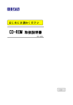
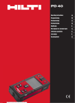
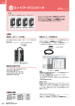
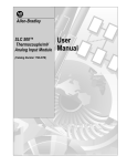
1
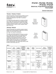
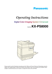
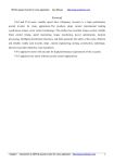
The product information in this catalog is for reference only. Please request the Engineering Drawing for the most current and accurate design information.
All non-RoHS products have been discontinued, or will be discontinued soon. Please check the products status on the Hirose website RoHS search at www.hirose-connectors.com, or contact your Hirose sales representative.
PC Card Single Slot SMT Connectors for the AV Market (that Support 5 V Cards)
IC15 Series
Reliable card ejection
■Features
Stroke:
11.7mm
Card ejection distance
6mm min
Ejection distance, molded-in guide
Low friction
2-point card ejection
Equipment outline
Three-stage card ejection
1. Reliable card ejection
Designed for the front mounted Audio/Visual equipment
the connectors eject the inserted card by applying force
equally at each edge of the card (distance of 6 mm
minimum), allowing easy hold of the card for the final
removal.
IC15: When card is inserted.
The button does not protrude without the card being
inserted, preventing it’s damage when carrying the
portable devices.
3. Secure board retention
Built-in 4 points of board retention posts assure that the
card insertion shock is not transferred to the solder joints.
4. Supports lead-free environments
All components use lead-free materials.
■Applications
DVD recorders, LCD TVs, PDP and other digital AV equipment
IC15: When card is not inserted.
Button does not protrude.
Button does not protrude.
In use
Press ejection button.
Ejection button pressed by mistake.
Button is released, protrudes for card ejection.
Button is inserted.
Card is ready
for ejection
2. New three-stage “Pop-Up” card ejection
mechanism
A60
IC15A
Ejection button does not protrude.
Press ejection button.
Card is ready for ejection
Damage prevention of
ejection button.
Card ejected
The product information in this catalog is for reference only. Please request the Engineering Drawing for the most current and accurate design information.
All non-RoHS products have been discontinued, or will be discontinued soon. Please check the products status on the Hirose website RoHS search at www.hirose-connectors.com, or contact your Hirose sales representative.
■Product Specifications
Current rating
Ratings
Voltage rating
0.5A
125V AC
Item
Operating temperature range
-55ç to +85ç (Note 1)
Storage temperature range
Relative humidity 95% max.
Operating humidity range
Storage humidity range
(No condensation)
Specifications
-40ç to +70ç (Note 1)
40% to 70% (Note 1)
Conditions
11. Insulation resistance
12. Withstanding voltage
13. Contact resistance
100 Mø min.
No flashover or insulation breakdown.
60 mø max. (Initial value)
14. Vibration
No electrical discontinuity of 100 ns or more.
15. Humidity
Insulation resistance: 100 Mø min.
16. Temperature cycle
Insulation resistance: 100 Mø min.
17. Durability (mating/unmating)
Contact resistance: 20mø max. from initial value
18.Resistance to soldering heat
No deformation of any component. No affect on contacts.
500 V DC
500 V AC / one minute
1mA DC
Frequency: 10 to 2000 Hz, single amplitude of 1.52 mm or
acceleration of 147m/s2 (peak), 4 hours / 3 axis
96 hours at temperature of 40ç±2ç and humidity of 90% to 95%
Temperature: -55ç ➝ +5ç to +35ç ➝ +85ç ➝ +5ç to +35ç
Duration: 30 ➝ 5 max. ➝ 30 ➝ 5 max. (Minutes) 5 cycles
10000 cycles at 400 to 600 cycles per hour
Reflow: At the recommended temperature profile
Manual soldering: 300 ç for 3 seconds
Note 1: Includes temperature rise caused by current flow.
Note 2: The term ”storage” refers to products stored for long period of time prior to mounting and use. Operating Temperature Range and Humidity
range covers non- conducting condition of installed connectors in storage, shipment or during transportation.
■Materials/Finish
SMT unit
Material
Finish
Remarks
Insulator
Component
Heat resistant thermoplastic compound
UL94V-0
Contacts
Brass
Color: Black
Contact area: Gold plated
Termination area: Tin plated
------------Tin plated
Ground/eject metal fittings
Positioning pin
Stainless steel
Brass
-------------------------------------
Guide unit
Component
Material
Finish
Remarks
Frame
Cover/Metal components
Spring
Ejection button
PBT
Stainless
Stainless steel
ABS
Color: Black
------------------------Color: Gray
UL94V-0
------------------------UL94V-HB
Note: Lead free products
A61
The product information in this catalog is for reference only. Please request the Engineering Drawing for the most current and accurate design information.
All non-RoHS products have been discontinued, or will be discontinued soon. Please check the products status on the Hirose website RoHS search at www.hirose-connectors.com, or contact your Hirose sales representative.
■Ordering information
● SMT unit
IC15 A - PDR - SF M - EJL
1
2
3
4
5
6
1
Series name: IC15
4
SF: Right angle surface mount
2
Stand off height
A: 2.2mm
5
M: With Vacuum pick-up plate
6
3
Terminal type
PDR: Reverse type (5V type)
Ejection button type
EJL: Left button eject
● Guide unit
IC15 A - G - P EJL
7
7
Series name:IC15
8
Stand off height
A: 2.2mm
9
G: Guide unit
8
9
10
11
10
Eject mechanism codes
P: Pop-up button
11
Ejection button type
EJL: Left button eject
Note: One SMT unit and one Guide unit constitute one assembly. They can not be ordered separate.
A62
The product information in this catalog is for reference only. Please request the Engineering Drawing for the most current and accurate design information.
All non-RoHS products have been discontinued, or will be discontinued soon. Please check the products status on the Hirose website RoHS search at www.hirose-connectors.com, or contact your Hirose sales representative.
■Reverse type
Left Pop-up button type
3
Eject metal components movable range
2.6
59.5
No.35
No.2
No.36
35.75MAX
No.34
SMT unit ( 1 )
No.1
10MAX
9.9(Card ejected)
Eject metal
components
movable range
51.45
59.1(Mounting screw pitch)
8
3
1.8(Ejector pushed-in for card withdrawal)
56MAX
86.1(Card fully inserted)
A
2.4
71.5
85.6(PC card length)
PAL
39MIN
20.5
11MAX
6
8MAX
No.68
15L
3
7
54(PC card width)
Guide unit ( 2 )
28.2
Outline of the PC card
37MAX
29MIN
Eject metal components movable range
No.68
C
No.35
8.2
10MAX
5
4.9
No.36
No.34
Stand off height
2.2mm
No.2
No.1
SMT unit (1)
Part Number
Guide unit (2)
CL No.
IC15A-PDR-SF-EJL
CL640-1500-7
IC15A-PDR-SFM-EJL
CL640-1502-2
Part Number
CL No.
IC15A-G-PEJL
CL640-1503-5
Weight (g)
18.4
18.7
1: Above illustration shows the SMT unit and the Guide unit connected together.
2: Dimensions for card fitting are in accordance with “PC card standard”.
3 Indicated dimensions are symmetrical to the center of the card insertion slot.
A63
The product information in this catalog is for reference only. Please request the Engineering Drawing for the most current and accurate design information.
All non-RoHS products have been discontinued, or will be discontinued soon. Please check the products status on the Hirose website RoHS search at www.hirose-connectors.com, or contact your Hirose sales representative.
BPCB mounting pattern
● Reverse type
● Stand off 2.2mm
2.65±0.05
55.05±0.05
1
Mounting area
(12.35)
16.75±0.05
(4.4)
52.4±0.05
Ø2
55.85±0.05
Ø1.9
+0.1
0 (Plated
+0.1
0
through hole)
(Plated through hole)
55.75±0.05
3.35±0.05
2-Ø2
10MIN
.8
Metal fitting mounting area
C
1
52.9MAX
1
59.1±0.05
1
66.8MIN
Note 1 Indicated dimensions are symmetrical to the center of the card insertion slot.
BPCB mounting pattern (Enlarged detail)
47.4725±0.05
4.9275±0.05
No.68
No.34
2±0.1
2±0.1
● Reverse type
68-0.37±0.03
P=0.635±0.03
Ø1.65±0.05
A64
No.1
No.2
No.35
Ø1.65±0.05
+0.1
0
.4
Ø1.9
Ø2
.4
Edge of the inserted PC card
The product information in this catalog is for reference only. Please request the Engineering Drawing for the most current and accurate design information.
All non-RoHS products have been discontinued, or will be discontinued soon. Please check the products status on the Hirose website RoHS search at www.hirose-connectors.com, or contact your Hirose sales representative.
BMethod of Attachment to the Board and Precautions
(1) Exercise caution when handling the Guide unit.
(1) If needed, re-position the push rod or the stroke arm as indicated in Fig.1
Guide unit
SMT unit
15L
A
A
Stroke arm
Push rod
PAL
PCB outline
Fig. 1
(2 : 1)
(2 : 1)
A
A
Interference
Interference
Fig. 2
A65
The product information in this catalog is for reference only. Please request the Engineering Drawing for the most current and accurate design information.
All non-RoHS products have been discontinued, or will be discontinued soon. Please check the products status on the Hirose website RoHS search at www.hirose-connectors.com, or contact your Hirose sales representative.
(2) Align the left and right locking tabs (Fig. 4) of the Guide unit shield plate with the left and right openings on the SMT unit
15L
insulator. (Fig. 3)
Shield plate
A
Pushrod
Stroke arm
PAL
Fig. 3
Opening
A
Locking tabs
Protrusions
SMT unit
PCB
Fig. 4
A66
Shield plate
The product information in this catalog is for reference only. Please request the Engineering Drawing for the most current and accurate design information.
All non-RoHS products have been discontinued, or will be discontinued soon. Please check the products status on the Hirose website RoHS search at www.hirose-connectors.com, or contact your Hirose sales representative.
(3) Assuring the correct alignment firmly press-down the shield plate of the Guide unit (at the areas “A”) into the SMT unit until a
loud “click” sound is heard. Both units should be now firmly locked together.
15L
Area A
Spring area – do not touch
A
Area A
Note 1: When placing the Guide unit over the SMT unit, DO NOT press on any other area than “A”.
(4) Attach the Guide unit in two places using recommended screws (Not supplied).
PAL
Screw description
Recommended Fastening Torque
M2∞0.4
0.12~0.16 (N • m)
Note 2: When attaching the screws exercise caution not to deform the shield plate.
Note 3: Do not insert/eject the PC card before the SMT unit and the Guide unit are fully mounted and locked.
Note 4: Metal components of these connector assemblies have sharp edges. Use caution when handling and assembling.
Note 5: Slight tool marks or cleaning fluid residue on the surfaces of the Guide unit will not affect form, fit or function of the assemblies.
A67
The product information in this catalog is for reference only. Please request the Engineering Drawing for the most current and accurate design information.
All non-RoHS products have been discontinued, or will be discontinued soon. Please check the products status on the Hirose website RoHS search at www.hirose-connectors.com, or contact your Hirose sales representative.
BRecommended temperature profile
250ç(PEAK)
250
220ç
Temperature(ç)
200
170ç
150
150ç
60s(MAX)
100
60~120s
50
25ç
0
START
Time (Seconds)
● Recommended conditions
• Reflow system: IR reflow
• Solder composition: Paste, 96.5%Sn/3.0%Ag/0.5%Cu (Flux content 10.5wt%)
• Test board: Glass epoxy 80mm∞125mm∞1.6mm thick
• Metal mask: 0.15mm thick
The temperature profiles are based on the above conditions.
In individual applications the actual temperature may vary, depending on solder paste type, volume/thickness and board
size/thickness. Consult your solder paste and equipment manufacturer for specific recommendations.
A68