1
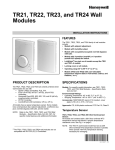
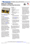
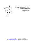
TP-8101, TP-8102, TP-8103,
TP-8124, TP-8125
Electronic, Proportional Controlling
Thermostats
General Instructions
TP-8101, TP-8102, TP-8103
These self-contained room temperature controllers conserve
energy in heating and/or cooling applications requiring a
single setpoint adjustment. See Table-1 for particular
characteristics.
The heating and cooling equipment is precisely controlled
from a single 1000 ohm Balco sensor operating through a
single controller for heating and/or cooling. The controller
provides a proportional output to control TAC System 8000
controlled devices for control of valves, dampers, electric
heat, DX coils, etc.
TP-8101,
TP-8102,
TP-8103
Single Setpoint
Adjustment
90
80
70
60
50
TP-8124, TP-8125
These self-contained room controllers conserve energy in
heating and/or cooling equipment in applications requiring
heating and cooling setpoint adjustment.
See Table-1 for particular characteristics.
The heating and cooling equipment is precisely controlled
from a single 1000 ohm Balco sensor operating through
independent heating and cooling controllers. These
controllers provide proportional outputs to control TAC
System 8000 controlled devices for control of valves,
dampers, electric heat, DX coils, etc. The heating output
(OP1 to COM) can be programmed for direct-acting or
reverse-acting operation. The cooling output (OP2 to COM)
provides a direct-acting output only.
TP-8124
& TP-8125
Dual
Setpoint
Adjustment
Table-1
Part Number
Dial
Marking
Control
Dial Range
TP-8101
°F & °C
55-85°F
TP-8101-116
°C
13-29°C
TP-8102
°F & °C
7-24°C
(45-75°F)
TP-8103
°F & °C
24-41°C
(75-105°F)
°F & °C
Heating
7-24°C
(45-75°F)
cooling
21-38°C
(70-100°F)
TP-8124 Dual
Setpoints
TP-8125
Dual
Setpoints
°F & °C
Printed in U.S.A. 8-08
Heating
7-24°C
(45-75°F)
Cooling
24-41°C
(75-105°F)
Throttling
Range for 3
Vdc Output
Change
2, 3, 6 and
20°F Factory
Set 3°F By
Jumper/Pins
Heating and
Cooling
2-10°F
Independently
Adj.
Factory Set
3°F
Input
Voltage
20 Vdc
13 mA
20 Vdc
23 mA
Output
Voltage
Control Action
Wiring
Connections
Number of
Controlled
Devices
2-15 Vdc
or
15-2 Vdc
Factory Set
Direct-acting
Jumper
Terminal 4 to 5
For
Reverse-acting
Jumper
Terminal 4 to 3
3 Color-coded
Pigtail Leads
Terminals for
Options See
Figure 2
6
TAC System
8000
Devices or 2
MP-5200
Series
Actuators
Heat 2-15 Vdc
or
15-2 Vdc
Cool
2-15 Vdc
Heating Factory
Set
Reverse-acting
Jumper J7
to pin B for
Direct-acting
Cooling
Direct-acting
only
Coded
Terminals
see Figure 3
6
TAC System
8000
Devices or 2
MP-5200
Series
Actuators in
both Heating
and Cooling
© Copyright 2008 TAC All Rights Reserved.
F-18097-8
Features
THROTTLING RANGE
1. TP-8124 meets ASHRAE 90-75 and DOE requirements.
TP-8125 meets DOD requirements.
2. Heating and cooling cannot operate simultaneously.
Throttling range (T.R.) is defined as the degrees (°F or °C)
change at the temperature sensor in order to cause a 6 to 9
Vdc controller output signal change.
3. Heating/cooling deadband obtained by adjustable dual
setpoints and throttling range.
4. Proportional outputs operate remote TAC System 8000
controlled devices such as valves, dampers, electric heat
coils, etc.
5. Concealed adjustments eliminate occupant tampering.
INSTALLATION
Open the carton and visually inspect the device for part
number and obvious defects before proceeding with the
installation.
Figure-2 Terminal Nomenclature TP-8101, TP-8102, and
TP-8103.
Mounting screws are provided.
Locate the controller where it will be exposed to unrestricted
natural air circulation and to the average conditions of the
controlled space. Do not locate it near sources of heat or cold
(such as lamps, motors, sunlight radiators and concealed
pipes or ducts within the wall) which might affect the control
point. Avoid locations where excessive vibration moisture.
Corrosive fumes or vapors are present, or where high radio
frequency or electromagnetic generating devices are near.
Dimensions
111 mm (4-3/8") high x 77 mm (2-7/8") wide x 41 mm (1-5/8")
deep.
Ambient Limits
Operation: 40 to 140°F (4.4 to 60°C). Storage: 40 to 160°F
(-40 to 71°C).
Figure-3 Terminal Nomenclature TP-8124 and TP-8125.
WIRING
Make all electrical connections according to installation wiring
diagrams. Comply with national and local electrical codes.
No. 18 multi-conductor thermostat cable may be used. Low
voltage Class 2 wire is acceptable, but No. 18 or larger 600V
wire should be used if splices are to be made in the same
junction box with the voltage wiring.
The controller may be installed on either a 52 mm x 102 mm
(2" x 4") flush switch box or a surface switch box. To install,
proceed as follows:
1. Wiring for the TP-8101, TP-8102 and TP-8103 is shown in
Figures 4 and 5. See Figures 6 and 7 for TP-8124 and
TP-8125 typical wiring.
Figure-1
2. “Pull” all wires required.
3. Connect all control wiring to the thermostat.
MODES OF OPERATION
1. Direct-acting control (DA): Increase in temperature at the
sensor causes the controller output signal to increase.
2. Reverse-acting control (RA): Increase in temperature at
the sensor causes the controller output signal to
decrease.
2
4. Remove the thermostat cover by loosening the screw at
the bottom of the cover. Pull the cover out from the
bottom and up to disengage it from the base.
5. Fasten the base to the box with the screws provided.
6. Replace the cover and tighten the cover screw.
© Copyright 2008 TAC All Rights Reserved.
F-18097-8
WIRING OF CONTROLLED DEVICES TO
CONTROLLER
Types of controlled devices and their power
supplies:
1. Filtered and regulated power supplies: All TAC System
8000 controlled devices except MP-52XX and MP-54XX
series actuators.
2. Filtered and unregulated power supplies: MP-54XX
series actuators.
3. Controlled devices with filtered and unregulated supplies.
Up to six controlled devices with the red leads (+20
terminals) can be connected together. Number of units
paralleled depends on the current (mA DC) requirements
of the controller of adaptor.
Table-2 Devices and Their Internal Supplies.
Filtered & Regulated
Filtered &
Unregulated
Unfiltered &
Unregulated
CC-8101
MP-54XX
Actuators
MP-52XX
Actuators
3. Unfiltered and unregulated power supplies: MP-52XX
series actuators.
CC-8102
General rules for wiring controllers to controlled
devices:
CC-8118 Series
CC-8103
CC-8218 Series
1. Never connect red lead (or +20 terminal) of any controlled
device which has a regulated power supply to the red lead
(or +20 terminal) of any other controlled device.
CC-8111 Series
2. Controlled devices with unfiltered and unregulated power
supplies must be filtered. TAC System 8000 controllers
will provide filtering for a maximum of two controlled
devices by connecting the two red leads (+20 terminals)
together at the controllers red lead (+20 terminal).
CP-8425 Series
CP-8301 Series
CP-8161 Series
CP-5501 Series
CP-8502 Series
Figure-4 TP-8101, TP-8102, and TP-8103 Typical Wiring without MP-52xx Actuators.
F-18097-8
© Copyright 2008 TAC All Rights Reserved.
3
Figure-5 TP-8101, TP-8102, and TP-8103 Typical Wiring with MP-52xx Actuators.
Figure-6 TP-8124 and TP-8125 Typical Wiring with One or No Mp-52xx Actuators.
4
© Copyright 2008 TAC All Rights Reserved.
F-18097-8
Figure-7 TP-8124 and TP-8125 Typical Wiring with Two MP-52xx Actuators.
Table-3 Throttling Range Resistor Values.
ADJUSTMENTS
oF
Auxiliary Resistor
TAC Part Number
1
4.3 Meg. ± 5%
E19-23-562
1.5
3.0 Meg. ± 5%
2.0
2.2 Meg. ± 5%
CYZR-481-860
2.5
1.8 Meg. ± 5%
CYZR-481-580
3.0
1.5 Meg. ± 5%
CYZR-481-680
3.5
1.2 Meg. ± 5%
CYZR-481-450
4.0
1 Meg. ± 5%
CYZR-481-610
4.5
975K, ± 1%
CYZR-862-496
5.0
866K, ± 1%
6.0
732K, ± 1%
7.0
619K, ± 1%
1. Remove the cover and turn the setpoint adjuster (SPA) to
the required temperature for heating mode (typically 65°F).
8.0
549K, ± 1%
9.0
487K, ± 1%
Turn the setpoint adjuster (SPB) to the required temperature for the cooling mode (typically 78°F).
10.0
432K, ± 1%
CYZR-862-462
15.0
287K, ± 1%
CYZR-862-445
20.0
215K, ± 1%
25.0
174K, ± 1%
CYZR-837-913
30.0
143K, ± 1%
CYZR-837-130
40.0
107K, ± 1%
50.0
84.5K, ± 1%
E19-64-390
60.0
69.8K, ± 1%
CYZR-837-890
TP-8101, TP-8102, TP-8103
1. Turn the setpoint adjuster to the required temperature
setting. Normally, no further adjustments are required.
2. Throttling range settings of 2, 3, 6 and 20° are available
by placing the T. R. jumper on the proper selector pin.
See Figure 8. For other throttling ranges (1 through 60°)
add a resistor to the auxiliary pins. Select the resistor
from the chart below. Place the T. R. jumper on the
auxiliary pin nearest the center of the controller.
TP-8124 and TP-8125
The cooling signal is direct-acting, and stages cooling or
proportionally opens a normally closed chilled water
valve with a temperature increase.
The heating signal is factory set for reverse-acting. With
a temperature decrease, the signal stages electric heat
or proportionally increases the electric heat output controlled by a TAC CP-8400 or CP-80000 Series SCR controller.
T. R.
CYZR-862-477
2. For applications that require a direct-acting signal in the
heating mode, such as normally open heating valve,
move jumper J7 to pin “B”.
F-18097-8
© Copyright 2008 TAC All Rights Reserved.
5
3. The Temperature Deadband between heating and
cooling is the difference in SPB and SPA settings. For
example, the deadband is 13°F with SPA at 65°F and
SPB at 78°F.
SERVICE
4. The throttling ranges are factory set at 3°F for heating and
cooling. These settings should not be changed for normal
applications. Increase the throttling range only to achieve
control stability (adjustable 2 to 10°F).
Note: The TP-8101, TP-8102 and TP-8103 have been
factory calibrated to produce a 7.5 Vdc output signal at the
yellow and blue leads (TO+ and TS-) when the setpoint and
the temperature at the sensing element agree.
To adjust, turn the T. R. dial to position the required T. R.
value closest to the thermostat cover.
5. Replace the cover.
TP-8101, TP-8102, TP-8103
1. Verify wiring per job wiring diagram.
2. Measure with a 20,000 ohm per Vdc VOM.
a. Power supply 20 Vdc Red (+) to blue (-) wires or test
point pins TS- and TS+ (+ end of the 47 μƒ capacitor).
b. Output 2 to 15 Vdc: Yellow (+) to blue (-) wires or TO+
and TS- test pins. The voltage varies between 2-15 as
the dial knob is rotated.
3. Consult EN 111 for additional service information.
4. Replace the controller if it is defective.
If calibration is necessary, proceed as follows:
1. Connect a 20,000 ohm per Vdc VOM between the yellow
(+) and blue (-) leads or TO+ and TS- pins on the
thermostat.
2. With the thermostat cover on, insert a 5/64” Allen wrench
through the hole on the right-hand side of the thermostat
into the setpoint potentiometer shaft.
3. Measure the temperature at the thermostat.
4. Adjust the thermostat setpoint by rotating the Allen
wrench until the setpoint dial reading equals the
temperature measured in step 3 above.
Figure-8 TP-8101, TP-8102, and TP-8103.
5. Using the thumb of your left hand, hold the knob in place.
Avoid touching the lower left-hand corner of the
thermostat where the sensor is located.
6. Rotate the Allen wrench until VOM reads 7.5 ± 3 Vdc.
7. The thermostat is calibrated.
TP-8124 and TP-8125
Note: The TP-8124 and TP-8125 have been factory
calibrated to produce 6.0 Vdc output signals at OP1 and OP2
to COM terminals when the setpoints and the temperatures
at the sensing element agree.
Test the power supply and output as follows:
1. Verify the wiring per the job wiring diagram.
2. Measure with a 20,000 ohm per Vdc VOM:
a. Power supply 20 Vdc: ±20 (+) to COM (-).
b. Heating output: OP1 (+) to COM (-), Vdc varies
between 2-15 as SPA is rotated.
c. Cooling output: OP2 (+) to COM (-). Vdc varies
between 2-15 as SPB is rotated.
Figure-9 TP-8124 or TP-8125.
3. Replace the controller if it is defective.
If calibration is necessary, proceed as follows:
1. Remove the thermostat cover. Note room temperature.
6
© Copyright 2008 TAC All Rights Reserved.
F-18097-8
between AB2 and COM connections.
2. If room temperature is 75°F or greater:
a. Connect VOM internally to OP2 (+) and COM (-). See
Figure 10 for details.
b. Rotate SPB until VOM reads 6.0 ± 3 Vdc. SPB pointer
must indicate the temperature measured. If not, hold
SPB shaft and rotate pointer (CCW) until it indicates
the temperature measured.
e. Rotate SPB until VOM reads 6.0 ± 3 Vdc. SPB should
read the measured temperature plus 10°F. If not, hold
SPB shaft and rotate pointer (CCW) until it indicates
the measured temperature plus 10°F.
SPB is calibrated.
SPB is calibrated.
c. Disconnect VOM lead from OP2 and reconnect to
OP1. Connect Jumper J7 to Pin A.
d. Connect 1 MEG ± 1% resistor (SYZE-13512 test kit)
between AB1 and 6.2 connections.
e. Rotate SPA until VOM reads 6.0 ± Vdc. SPA should
read temperature measured minus 10°F. If not, hold
SPA shaft and rotate pointer (CCW) until it indicates
temperature measured minus 10°F.
SPA is calibrated.
3. If room temperature is 74°F or less:
a. Connect VOM internally to OP1 (+) and COM (-). See
Figure11 for details.
b. Rotate SPA until VOM reads 6.0 ± 3 Vdc. SPA must
indicate the temperature measured. If not, hold SPA
shaft and rotate the pointer (CCW) until it indicates
the measured temperature.
SPA is calibrated.
c. Disconnect VOM lead from OP1 and re-connect to
OP2. Connect Jumper J7 to Pin A.
Figure-10
d. Connect 1 MEG, ± 1% resistor (SYZE-13512 test kit)
Figure-11 TP-8101, TP-8102., and TP-8103 Block Diagram.
F-18097-8
© Copyright 2008 TAC All Rights Reserved.
7
Figure-12 TP-8124 and TP-8125 Block Diagram.
OPTIONS
Summer-Winter Changeover
TP-8101, TP-8102, TP-8103
This is accomplished without remote setpoints or selective
ratio discharge. The controller operates in either the DA or RA
mode. See Figure 13.
(TP-8124 and TP-8125 have no options.)
Jumper 4 to 5 - DA (directing-acting): A temperature increase
causes an output voltage increase.
Remote Setpoint
Install the AT-8100 Series remote setpoint adjuster between
terminals 1, 2 and 7. These are used for applications where
the setpoint adjustment is mounted remote from the controller.
See Figure 15, 16, or 17.
Jumper 3 to 4 - RA (reverse-acting): A temperature increase
causes an output voltage decrease.
Remove the dial rim from the setpoint knob using wire cutters.
Turn the dial to 70°F. The AT-11-404 blank cover is
recommended to prevent dust infiltration.
Connect the ratio discharge sensor (Figure 20) to the room
controller as shown in Figure 15, 16 or 17. This is used for
room and discharge control applications.
Remote Sensing
Winter-Summer Operation
Remove the internal 1000 ohm sensor and install the remote
sensor (TS-8000 Series) between terminals 7 and 8. This is
used for applications where the sensor is mounted remote
from the controller. See Figure 14.
This is accomplished using selective ratio discharge and/or
remote setpoints. For direct-acting see Figure 15. For
reverse-acting, see Figure 16. For winter-summer switching,
see Figure 17.
Selective Ratio Discharge Control
For panel mounting, see Figure 19.
8
© Copyright 2008 TAC All Rights Reserved.
F-18097-8
Figure-13 TP-8101, TP-8102, and TP-8103 with Single Pole Double Throw (SPDT) Winter-Summer Switching.
Figure-14 TP-8101, TP-8102, and TP-8103 with Remote Sensor.
F-18097-8
© Copyright 2008 TAC All Rights Reserved.
9
Figure-15 TP-8101, TP-8102, and TP-8103 with Remote Setpoint and/or Selective Ratio Discharge Sensor.
Direct-Acting Output Only.
Figure-16 Tp-8101, TP-8102, and TP-8103 with Remote Setpoint and/or Selective Ratio Discharge Sensor
Reverse-Acting Output Only.
10
© Copyright 2008 TAC All Rights Reserved
F-18097-8
Figure-17 Tp-8101, TP-8102, and TP-8103 with Remote Setpoint and/or Selective Ratio Discharge Sensor with Double Pole
Double Throw (DPDT) Winter-Summer Switching.
Figure-18 TP-8101, TP-8102, and TP-8103 with Night Depression and/or Morning Warm-Up.
F-18097-8
© Copyright 2008 TAC All Rights Reserved
11
Figure-19 TP-8101, TP-8102, and TP-8103 Mounted on AD-8951.
Figure-20 TS-8601 Ratio Discharge Sensor for use with TP-8101, TP-8102, and TP-8103.
MAINTENANCE
This is a quality product. Regular maintenance of the total system
is recommended to assure optimum performance.
Copyright 2007, TAC
All brand names, trademarks and registered
trademarks are the property of their respective
owners. Information contained within this
document is subject to change without notice.
F-18097-8
TAC
1354 Clifford Avenue
P.O. Box 2940
Loves Park, IL 61132-2940
www.tac.com