1
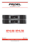
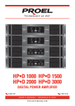
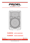
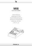
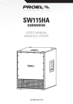
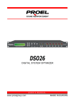
USER’S MANUAL
MANUALE UTENTE
www.proel.com
FCC COMPLIANCE NOTICE
This device complies with part 15 of the FCC rules. Operation is subject to the following two
conditions:
(1) This device may not cause harmful interference, and
(2) this device must accept any interference received, including interference that may cause
undesired operation.
CAUTION: Changes or modifications not expressly approved by the party responsible for
compliance could void the user’s authority to operate the equipment.
NOTE: This equipment has been tested and found to comply with the limits for a Class B digital
device, pursuant to part 15 of the FCC Rules. These limits are designed to provide reasonable
protection against harmful interference in a residential installation. This equipment generates,
uses, and can radiate radio frequency energy and, if not installed and used in accordance
with the instruction manual, may cause harmful interference to radio communications.
However, there is no guarantee that interference will not occur in a particular installation. If
this equipment does cause harmful interference to radio or television reception, which can
be determined by turning the equipment off and on, the user is encouraged to try to correct
the interference by one or more of the following measures:
• Reorient or relocate the receiving antenna.
• Increase the separation between the equipment and receiver.
• Connect the equipment into an outlet on a circuit different from that to which the receiver
is connected.
• Consult the dealer or an experienced radio/TV technician for help.
This marking shown on the product or its literature, indicates that it should not be disposed with other household wastes at the end of its
working life. To prevent possible harm to the enviroment or human health from uncontrolled waste disposal, please separate this from other
types of wastes and recycle it responsibly to promote the sustainable reuse of material resources. Household users should contact either
the retailer where they purchased this product, or their local government office, for details of where and how they can take this item for
environmentally safe recycling. Business users should contact their supplier and check the terms and conditions of the purchase contract.
This product should not be mixed with other commercial wastes for disposal.
The lightning flash with arrowhead symbol within an equilateral triangle is intended to alert the user to the presence of uninsulated “dangerous
voltage” within the product’s enclosure, that may be of sufficient magnitude to constitute a risk of electric shock to persons.
The exclamation point within an equilateral triangle is intended to alert the user to the presence of important operating and maintenance
(servicing) instructions in the literature accompanying the appliance.
The information contained in this publication has been carefully prepared and checked. However no responsibility will be taken for any errors. All
rights are reserved and this document cannot be copied, photocopied or reproduced in part or completely without written consent being obtained
in advance from PROEL. PROEL reserves the right to make any aesthetic, functional or design modification to any of its products without any prior
notice. PROEL assumes no responsibility for the use or application of the products or circuits described herein.
Il marchio riportato sul prodotto o sulla documentazione indica che il prodotto non deve essere smaltito con altri rifiuti domestici al termine
del ciclo di vita. Per evitare eventuali danni all’ambiente si invita l’utente a separare questo prodotto da altri tipi di rifiuti e di riciclarlo in
maniera responsabile per favorire il riutilizzo sostenibile delle risorse materiali. Gli utenti domestici sono invitati a contattare il rivenditore
presso il quale è stato acquistato il prodotto o l’ufficio locale preposto per tutte le informazioni relative alla raccolta differenziata e al
riciclaggio per questo tipo di prodotto. Gli utenti aziendali sono invitati a contattare il proprio fornitore e verificare i termini e le condizioni
del contratto di acquisto. Questo prodotto non deve essere smaltito unitamente ad altri rifiuti commerciali.
Il simbolo del lampo con freccia in un triangolo equilatero intende avvertire l'utilizzatore per la presenza di "tensioni pericolose" non isolate
all'interno dell'involucro del prodotto, che possono avere una intensità sufficiente a costituire rischio di scossa elettrica alle persone.
Il punto esclamativo in un triangolo equilatero intende avvertire l'utilizzatore per la presenza di importanti istruzioni per l'utilizzo e la
manutenzione nella documentazione che accompagna il prodotto.
Le informazioni contenute in questo documento sono state attentamente redatte e controllate. Tuttavia non è assunta alcuna responsabilità per
eventuali inesattezze. Tutti i diritti sono riservati e questo documento non può essere copiato, fotocopiato, riprodotto per intero o in parte senza previo
consenso scritto della PROEL. PROEL si riserva il diritto di apportare senza preavviso cambiamenti e modifiche estetiche, funzionali o di design a
ciascun proprio prodotto. PROEL non assume alcuna responsabilità sull’uso o sul l’applicazione dei prodotti o dei circuiti qui descritti.
INDEX
INDICE
FCC COMPLIANCE NOTICE . . . . . . . . . . . . . . . . . . . . . . . . . 2
TECHNICAL SPECIFICATIONS . . . . . . . . . . . . . . . . . . . . . . . 3
SETUP AND RACK MOUNTING (FIG. 1 / 2) . . . . . . . . . . . . 4
LOUDSPEAKER CABLE . . . . . . . . . . . . . . . . . . . . . . . . . . . . . 4
CONNECTIONS . . . . . . . . . . . . . . . . . . . . . . . . . . . . . . . . . . . 5
SUGGESTED CONFIGURATIONS . . . . . . . . . . . . . . . . . . . . . 5
LPN FILTER RESPONSE (FIG. 3). . . . . . . . . . . . . . . . . . . . . . 5
CONTROL PANEL (FIG.4) . . . . . . . . . . . . . . . . . . . . . . . . . . . 6
REAR PANEL (FIG.5) . . . . . . . . . . . . . . . . . . . . . . . . . . . . . . . 6
CONFIGURATION EXAMPLES (FIG.6/7/8). . . . . . . . . . . . . . 7
SAFETY AND PRECAUTIONS . . . . . . . . . . . . . . . . . . . . . . . 8
IN CASE OF FAULT . . . . . . . . . . . . . . . . . . . . . . . . . . . . . . . . 8
TROUBLESHOOTING . . . . . . . . . . . . . . . . . . . . . . . . . . . . . . 8
CE CONFORMITY. . . . . . . . . . . . . . . . . . . . . . . . . . . . . . . . . . 9
PACKAGING, SHIPPING AND COMPLAINT . . . . . . . . . . . 9
WARRANTY AND PRODUCTS RETURN . . . . . . . . . . . . . . . 9
INSTALLATION AND DISCLAIMER . . . . . . . . . . . . . . . . . . . 9
POWER SUPPLY AND MAINTENANCE . . . . . . . . . . . . . . . 9
GENERAL INFORMATION . . . . . . . . . . . . . . . . . . . . . . . . . 10
SETUP AND RACK MOUNTING. . . . . . . . . . . . . . . . . . . . . 10
FRONT PANEL (FIG.4) . . . . . . . . . . . . . . . . . . . . . . . . . . . . . 10
REAR PANEL (FIG.5) . . . . . . . . . . . . . . . . . . . . . . . . . . . . . . 11
ADVANCED FEATURES . . . . . . . . . . . . . . . . . . . . . . . . . . . . 13
SPECIFICHE TECNICHE . . . . . . . . . . . . . . . . . . . . . . . . . . . . 3
INSTALLAZIONE A RACK (FIG. 1 / 2). . . . . . . . . . . . . . . . . . 4
CAVO ALTOPARLANTE . . . . . . . . . . . . . . . . . . . . . . . . . . . . . 4
CONNESSIONI. . . . . . . . . . . . . . . . . . . . . . . . . . . . . . . . . . . . 5
CONFIGURAZIONI SUGGERITE . . . . . . . . . . . . . . . . . . . . . . 5
RISPOSTA FILTRO LPN (FIG. 3) . . . . . . . . . . . . . . . . . . . . . . 5
PANNELLO DI CONTROLLO (FIG.4) . . . . . . . . . . . . . . . . . . . 6
PANNELLO POSTERIORE (FIG.5) . . . . . . . . . . . . . . . . . . . . . 6
ESEMPI CONFIGURAZIONI (FIG.6/7/8) . . . . . . . . . . . . . . . . 7
AVVERTENZE PER LA SICUREZZA . . . . . . . . . . . . . . . . . . 14
IN CASO DI GUASTO . . . . . . . . . . . . . . . . . . . . . . . . . . . . . 14
PROBLEMATICHE COMUNI . . . . . . . . . . . . . . . . . . . . . . . . 14
CONFORMITÀ CE . . . . . . . . . . . . . . . . . . . . . . . . . . . . . . . . 15
IMBALLAGGIO, TRASPORTO E RECLAMI . . . . . . . . . . . . 15
GARANZIE E RESI . . . . . . . . . . . . . . . . . . . . . . . . . . . . . . . . 15
INSTALLAZIONE E LIMITAZIONI D’USO . . . . . . . . . . . . . 15
ALIMENTAZIONE E MANUTENZIONE . . . . . . . . . . . . . . . 15
INFORMAZIONI GENERALI . . . . . . . . . . . . . . . . . . . . . . . . 16
INSTALLAZIONE E MONTAGGIO A RACK . . . . . . . . . . . . 16
PANNELLO FRONTALE . . . . . . . . . . . . . . . . . . . . . . . . . . . . 16
PANNELLO POSTERIORE . . . . . . . . . . . . . . . . . . . . . . . . . . 17
FUNZIONI AVANZATE . . . . . . . . . . . . . . . . . . . . . . . . . . . . 19
TECHNICAL SPECIFICATIONS
SPECIFICHE TECNICHE
MODEL
HPX4600
HPX6000
Power 8 ohm *
850 W
1200 W
Power 4 ohm *
1400 W
2000 W
Power 2 ohm **
2300 W
3000 W
Power BRIDGE 8 ohm *
3000 W
4100 W
Power BRIDGE 4 ohm **
4600 W
6000 W
Output Stage
Class 3H
Class 3H
20 Hz - 20 KHz
20 Hz - 20 KHz
Frequency response (+0/-0.5 dB)
Input Sensitivity (selectable)
Input Connectors / Impedance
0.775 Vrms (0 dBu) / 1.0 Vrms (0 dBV) / 32 dB (fixed GAIN)
XLR M (with XLR F LINK), 20 Kohm (balanced), 10 Kohm (unbalanced)
Output Connectors
Damping Factor
Slew Rate
S/N Ratio (unweighted)
THD+N
Controls
LED Indicators
SPEAKON and Binding Post
> 200
> 200
> 20 V/uS
> 20 V/uS
> 90 dB
> 90 dB
< 0.1%
< 0.1%
INPUT LEVEL, INPUT SENSITIVITY, STEREO/BRIDGE/PARALLEL, SOFT CLIPPING
POWER, ON, PARALLEL, BRIDGE, SIGNAL, LIMIT, PROTECT
Cooling
Protections
Mains Supply Voltage
Variable speed DC fan
AC low power, DC, thermal, short circuit, VHF, CLIP limiter, SOFT CLIP limiter
230 VAC (±10%) 50/60 Hz or 120VAC (±10%) 50/60 Hz
Maximum Consumption
2330 VA
3320 VA
Rated Consumption ***
620 VA
830 VA
Standby Consumption
Dimensions (W x H x D)
Weight
5 VA
6 VA
483 x 89 x 505 mm
19" x 3.5" x 19.9" (2U rack)
483 x 89 x 505 mm
19" x 3.5" x 19.9" (2U rack)
13 Kg (28.7 lb)
13,6 Kg (29.9 lb)
* RMS both channel THD < 1%
** 40 ms burst
*** Rated consumption is measured with pink noise with a crest factor of 12 dB, this can be considered a standard music program.
INDICE / INDEX
specifications
3
SETUP AND RACK MOUNTING (FIG. 1 / 2)
INSTALLAZIONE A RACK (FIG. 1 / 2)
RECOMMENDED INSTALLATION
INSTALLAZIONE RACCOMANDATA
FIG.1
FRONT
FRONTALE
REAR
POSTERIORE
COLD AIR
HOT AIR
FIG.2
ARIA FREDDA
ARIA CALDA
8U OPEN RACK
RACK aperto 8U
EVENTUAL INSTALLATION WITH CLOSED BACK
EVENTUALE INSTALLAZIONE CON RETRO CHIUSO
HOT AIR
ARIA CALDA
FRONT
FRONTALE
REAR (closed)
POSTERIORE (chiuso)
COLD AIR
ARIA FREDDA
10U closed RACK
RACK chiuso 10U
15 cm
6 inch
LOUDSPEAKER CABLE
CAVO ALTOPARLANTE
ENGLISH: Loudspeaker Line Losses (maximum permissible line lengths for 0.5dB losses, voltage or spl)
ITALIANO: Perdite di collegamento linee Altoparlanti (massima lunghezza possibile per perdite inferiori a 0.5dB, tensione o spl)
4 ohm load
8 ohm load
Wire section data
PROEL recommended cables
feet
meter
feet meter
mm²
AWG
2 wires
4 wires
2 wires Fire-resistant
75
25
150
50
4.0
12
HPC624
HPC644
HPC624FR
50
17.5
100
35
2.0
14
HPC620
HPC640
HPC520
30
10
60
20
1.5
16
HPC610
20
7.5
40
15
1.0
18
HPC605
4 wires Fire-resistant
HPC540
HPC510
this is a short extraction of the wide assortment of cables available from PROEL, please visit our website at www.proelgroup.com
4
FIG. 1 / 2
CONNECTIONS
INPUT
Balanced male XLR
CONNESSIONI
hot
ground
cold
cold
ground
hot
INPUT (ingresso)
XLR bilanciato maschio
LINK
Balanced female XLR
LINK (rilancio ingresso)
XLR bilanciato femmina
negative / black / nero
1-
40 mm
1.6 "
20 mm
0.8 "
15 mm
0.6 "
8 mm
0.3 "
n.c.2+
1-
2-
1+
BLACK
BLACK
RED
RED
1+
n.c.
SPEAKER POWER OUTPUTS
POWER OUTPUT - uscite altoparlanti
Neutrik NL4 Speakon Cable Connector
Connettore per cavo tipo Speakon Neutrik NL4
PROEL code - NL4FX
Codice PROEL - NL4FX
BINDING POST speaker output
uscite altoparlanti BINDING POST
CONFIGURAZIONI SUGGERITE
HPX4600
HPX6000
2x NEOS122PX
2x NEOS152PX
2x NEOS118PX
1x NEOS218PX
2x EDGE15CXPB
1x EDGE218SP
set as:
example
figures:
STEREO or
PARALLEL
This table is a short-form of some
sound system examples composed
of PROEL loudspeakers. These
are a few portion of the speaker
products in catalogue at the moment
of printing.
LOUDSPEAKERS
SUGGESTED CONFIGURATIONS
positive / red / rosso
6
Questa tabella è un riassunto di
alcuni esempi di sistema composti
con altoparlanti PROEL. Questa è
una porzione degli altoparlanti in
catalogo al momento della stampa.
2x EDGESW121P
connections
5
6
CONTROL PANEL (FIG.4)
PANNELLO DI CONTROLLO (FIG.4)
REAR PANEL (FIG.5)
PANNELLO POSTERIORE (FIG.5)
FIG. 3 / 4
CONFIGURATION EXAMPLES (FIG.6/7/8)
ESEMPI CONFIGURAZIONI (FIG.6/7/8)
STEREO STANDARD SETUP
FIG.6
4 or 8 ohm
loudspeakers
BRIDGE SETUP
FIG.7
8 ohm or 4 ohm *
loudspeaker
SUB-SYSTEM FULL RANGE SETUP
FIG.8
8 ohm
satellite
4 ohm
system sub+sat
8 ohm
subwoofer
FIG. 5 / 6 / 7
7
SAFETY AND PRECAUTIONS
•
CAUTION: Before using this product read carefully the following safety instructions. Take a look of this manual entirely and preserve it for future
reference.
When using any electric product, basic precautions should always be taken, including the following:
– To reduce the risk, close supervision is necessary when the product is used near children.
– Protect the apparatus from atmospheric agents and keep it away from water, rain and high humidity places.
– This product should be site away from heat sources such as radiators, lamps and any other device that generate heat.
– This product should be located so that its location or position does not interfere with its proper ventilation and heating dissipation.
– Care should be taken so that objects and liquids do not go inside the product.
– The product should be connected to a power supply mains line only of the type described on the operating instructions or as marked on the
product. Connect the apparatus to a power supply using only power cord included making always sure it is in good conditions.
–
WARNING: The mains plug is used as disconnect device, the disconnect device shall remain readily operable.
– Do not cancel the safety feature assured by means of a polarized line plug (one blade wider than the other) or with a earth connection.
– Make sure that power supply mains line has a proper earth connection.
– Power supply cord should be unplugged from the outlet during strong thunderstorm or when left unused for a long period of time.
– Do not place objects on the product’s power cord or place it in a position where anyone could trip over, walk on or roll anything over it. Do not
allow the product to rest on or to be installed over power cords of any type. Improper installations of this type create the possibility of fire hazard
and/or personal injury.
Sound Level dBA
Typical
– This product in combination with loudspeakers may be capable of producing Duration Per Day
In Hours
Slow Response
Example
sound levels that could cause permanent hearing loss. Exposure to extremely high
8
90
Duo in small club
noise levels may cause permanent hearing loss. Individuals vary considerably
in susceptibility to noise-induced hearing loss, but nearly everyone will lose 6
92
some hearing if exposed to sufficiently intense noise for a period of time. The 4
95
Subway Train
U.S. Government’s Occupational Safety and Health Administration (OSHA) has
3
97
specified the permissible noise level exposures shown in the following chart.
100
Very loud classical music
According to OSHA, any exposure in excess of these permissible limits could 2
result in some hearing loss. To ensure against potentially dangerous exposure 1.5
102
to high sound pressure levels, it is recommended that all persons exposed 1
105
Traffic noise
to equipment capable of producing high sound pressure levels use hearing
110
protectors while the equipment is in operation. Ear plugs or protectors in the ear 0.5
canals or over the ears must be worn when operating the equipment in order to 0.25 or less
115
Loudest parts at a rock concert
prevent permanent hearing loss if exposure is in excess of the limits set forth
here. Keep your's attention that childrens and pets are more suscetible to excessive noise levels.
IN CASE OF FAULT
•
–
–
–
–
–
•
In case of fault or maintenance this product should be inspected only by qualified service personnel when:
There is a flaw either in the connections or in the supplied connecting cables.
Liquids have spilled inside the product.
The product has fallen and been damaged.
The product does not appear to operate normally or exhibits a marked change in performance.
The product has been losted liquids or gases or the enclosure is damaged.
Do not operate on the product, it has no user-serviceable parts inside, refer servicing to an authorized maintenance centre.
TROUBLESHOOTING
8
No Power
• The amplifier's "POWER" switch is off.
• Make sure the mains AC outlet is live (check if LED PWR lights up).
• Make sure the mains plug is securely plugged into mains AC outlet.
No Sound
• Is the input LEVEL control for the channel turned up?
• Is the SIGNAL LED illuminated? If not check if your signal level is too low or check the signal cable, mixer and other
equipment setting and cabling.
• Are you sure your signal cables works properly? check it using a cable tester or replacing with a new one.
• Is the speaker cable connector correctly connected? if it is a SPEAKON turn it clockwise until it clicks.
• Are you sure your power cable works properly? check it using a cable tester or replacing with a new one.
No Sound and the
Amplifier gets too hot
• The amplifier temperature protections trips, re-locate the amplifier in a more ventilated location.
No Sound and
Protection trip
(LED PROTECT always
on)
• Could be a possible short circuit at the amplifier loudspeakers outputs, the speaker’s inputs or in the cabling. Locate
and remove the short circuit.
•The impedance of the loudspeakers connected is too low. If more speakers are connected in parallel at the outputs
reduce this number disconnecting a speaker.
• If no load connected the protection trips the same, a DC voltage has been detected in the amplifier’s output circuit and
you have to contact you nearest service assistance center to repair the amplifier.
Distorted Sound
• Input signal level is too high. Turn down your level controls.
NOTE: The amplifiers should never be operated at a level which causes the amplifier Clip LEDs to illuminate constantly.
Different channel
level
• Check if are using a balanced cable for one channel and an unbalanced one for the other, as this would cause a
considerable difference in channel levels.
• Be sure that your loudspeaker system is fully connected and both loudspeakers have the same impedance.
english
Noise / Hum
• Whenever possible, preferably use only balanced cables. Unbalanced lines may also be used but may result in noise
over long cable runs.
• Sometimes it helps to plug all audio equipment into the same AC circuit so they share a common ground.
CE CONFORMITY
• Proel products comply with directive 89/336/EEC (EMC) and following modifications 92/31/EEC and 93/68/EEC, as stated
in EN 55103-1 and EN 55103-2 standards and with directive 73/23/EEC (LVD) and following modifications 93/68/EEC, as
stated in EN 60065 standard.
• Under the EM disturbance, the ratio of signal-noise will be changed above 10dB.
PACKAGING, SHIPPING AND COMPLAINT
• This unit package has been submitted to ISTA 1A integrity tests. We suggest you control the unit conditions immediately after unpacking it.
• If any damage is found, immediately advise the dealer. Keep all unit packaging parts to allow inspection.
• Proel is not responsible for any damage that occurs during shipment.
• Products are sold “delivered ex warehouse” and shipment is at charge and risk of the buyer.
• Possible damages to unit should be immediately notified to forwarder. Each complaint for manumitted package should be done within eight days
from product receipt.
WARRANTY AND PRODUCTS RETURN
• Proel products have operating warranty and comply their specifications, as stated by manufacturer.
• Proel warrants all materials, workmanship and proper operation of this product for a period of two years from the original date of purchase. If
any defects are found in the materials or workmanship or if the product fails to function properly during the applicable warranty period, the owner
should inform about these defects the dealer or the distributor, providing receipt or invoice of date of purchase and defect detailed description.
This warranty does not extend to damage resulting from improper installation, misuse, neglect or abuse. Proel S.p.A. will verify damage on returned
units, and when the unit has been properly used and warranty is still valid, then the unit will be replaced or repaired. Proel S.p.A. is not responsible
for any "direct damage" or "indirect damage" caused by product defectiveness.
INSTALLATION AND DISCLAIMER
• Proel products have been expressly designed for audio application, with signals in audio range (20Hz to 20kHz). Proel has no liability for damages
caused in case of lack of maintenance, modifications, improper use or improper installation non-applying safety instructions.
• These amplifiers are adapted in a properly ventilated, standard professional 19" rack. These units feature ventilation holes on the front and back
panels. Absolutely do not obstruct the ventilation holes. Blocked ventilation can cause damages and fire.
• Do not locate sensitive high-gain equipment such as mixer, preamplifiers, recorders or AD/DA conversion units directly above or below these
amplifiers. Because these amplifiers have a high power density, it ha a strong magnetic field which can induce hum into unshielded devices that
are located nearby. If an equipment rack is used, we recommend locating the amplifier in the bottom of the rack and the mixer, preamplifier or other
sensitive equipment at the top.
• Locate the speakers as far away as possible from radio or television receivers or other sensitive equipment. These amplifiers have a strong
magnetic field which can induce hum and noise into unshielded devices that are located nearby with consequent deterioration of reception of image
and sound.
• Proel S.p.A. reserves the right to change these specifications at any time without notice.
• Proel S.p.A. declines any liability for damages to objects or persons caused by lacks of maintenance, improper use, installation not performed
with safety precautions and at the state of the art.
POWER SUPPLY AND MAINTENANCE
• Clean only with dry cloth.
• Check periodically that the slots for its proper ventilation and heating dissipation are not obstructed by dust, remove the dust using a dry brush
or a compressed air gun.
• These amplifiers have been designed with CLASS I construction and must be connected always to a mains socket outlet with a proctetive earth
connection (the third grounding prong).
• Before connecting the product to the mains outlet make certain that the mains line voltage matches that shown on the rear of the product, a
tolerance of up to ±10% is acceptable.
• To disconnect these equipment from the AC Mains, disconnect the power supply cord plug from the AC receptacle.
• Inside the amplified loudspeakers are present special safety devices such as:
9 Transformer and amplifier over-heating protection.
9 Protection against excessive power applied at each speaker.
•
THE REPLACEMENT OF FUSES INSIDE THE APPARATUS MUST BE MADE ONLY BY QUALIFIED PERSONNEL.
•
CHECK THE CONDITION OF THE PROTECTION FUSE, ACCESSIBLE OUTWARD, ONLY WITH THE APPARATUS SWITCHED OFF AND
DISCONNECTED FROM THE MAINS LINE OUTLET.
•
REPLACE THE PROTECTION FUSE ONLY WITH SAME TYPE AS SHOWN ON THE PRODUCT.
•
IF AFTER THE SUBSTITUTION, THE FUSE INTERRUPTS AGAIN THE APPARATUS WORKING, DO NOT TRY AGAIN THEN CONTACT THE PROEL
SERVICE CENTER.
english
9
GENERAL INFORMATION
Thank you for having chosen a PROEL product. HPX is a new series of PROEL power amplifiers designed to provide to
entertainers and audio professionals quality performance and maximum portability at a very affordable price.
Combining rock-solid CLASS H power stages to extremely efficient SWITCH MODE power supplies, the HPX amplifiers
delivers from 900W to 6000W of pure power to your speaker system, providing clear and defined highs together with
extremely punchy lows. All the models feature a true 2-ohm operation, providing a cost effective power solution for the
most demanding sound reinforcement applications.
Thanks to the SMPS light-weight technology and to the efficient cooling systems, the HPX come in a very compact and
portable package, yet sturdy enough to provide the maximum protection and durability over the years.
HPX4600 and HPX6000, feature a 3-tier CLASS H power stage, providing very high power level in a highdensity structure.
With an overall efficiency higher than 75% and a comprehensive set of controls, including a 3-position GAIN selector and
switchable SOFT CLIP LIMITERS, they represent a cost-effective solution also for large sound reinforcement systems
requiring very high power levels combined to top quality performance.
The front panel, with very comfortable die-cast handles and removable dust filters, features a comprehensive set of LED
indicators together with detented level controls. The connections includes XLR for the inputs and the links, SPEAKON
and binding post for the outputs.
SETUP AND RACK MOUNTING
All HPX amplifiers will mount in two units of a standard 19" (48.3cm) rack (the front panel is provided of four mounting
holes). HPX amplifiers use a forced-air cooling system to mantain a low operating temperature. Drawn by an internal fan,
cold air enters through the slots in the front panel and flows over and through internal components, then the hot air gets
out from the rear panel slots (as shown on figure 1). The HPX amplifiers drive the fan using a variable-speed DC circuit,
which is controlled by sensing the heat sink temperature. The fan speed will increase only when the temperature of either
heat sink requires it, which keeps fan noise to a minimum and helps cut dust accumulation inside.
NOTE: In order to prevent the dust accumulation inside the amplifier, the two air vents on front panel have a dust filter.
Each time these filters are dirty (it depends on enviroment conditions) you have to remove the air slots using a phillips
screwdriver (as shown on figure 2) and clean the dust filter using compressed air or a soft brush.
Under extreme thermal load, the fan will force a very large volume of air through the heat sinks. If the amplifier overheats,
another sensing circuit shuts down the amplifier to cut off power until it cools to a safe temperature.
IMPORTANT: The exhaust hot air is forced out through the rear of the chassis (see figure). ABSOLUTELY DO NOT
OBSTRUCT THE FRONT AND REAR OPENINGS and always let them free from cables or other materials.
If the amplifier is rack mounted, make sure the exhaust air can flow without resistance from front to back side of the rack.
Therefore we suggest to use only rack stands with front and back cover completely removed (Proel KR10AD as example
for fixed installation or Proel CR series for touring use). In this case amplifiers may be stacked directly on top of each
other (no space needed between units), starting from the bottom of the rack.
We advise against the use of rack with closed backs (or close to a back wall), but if you can do otherwise, we suggest to
leave at least one standard rack space of opening between every two amplifiers and to make sure there is enough space
at the rear of the amplifiers to allow the air to escape (at least 15 cm or 6 inch).
FRONT PANEL (FIG.4)
1. Cooling vent
Removable cooling vent: always keep it clean from dust.
2. Power indicator
Yellow LED: when lighted indicates AC power is available.
3. Power switch
Amplifier is "ON" when the switch is in the "I" position.
4. ON indicator
Green LED: when lighted indicates that the amplifier has been turned on.
5. Level control Channel 1
Rotary detented level control: in STEREO and PARALLEL operation it attenuates the level of the signal sent to the channel
1 of the amplifier, while in BRIDGE operation it operates as single control to attenuate the level of the signal sent to both
the channels.
The attenuation ranges from “∞” fully closed (the signal is completely attenuated) to “0” fully open, nominal level (the
signal is not attenuated in any way, so is fed to the amplifier channel at the same level at which it arrives on input).
6. Level control Channel 2
Rotary detented level control: in STEREO and PARALLEL operation it attenuates the level of the signal sent to the channel
10
english
2 of the amplifier. In BRIDGE operation it doesn't work.
The attenuation ranges from “∞” fully closed (the signal is completely attenuated) to “0” fully open, nominal level (the
signal is not attenuated in any way, so is fed to the amplifier channel at the same level at which it arrives on input).
7. Channel 1 SIGNAL indicator
Green LED illuminates to indicate the presence of the signal at the amplifier channel 1 output.
8. Channel 2 SIGNAL indicator
Green LED illuminates to indicate the presence of the signal at the amplifier channel 2 output.
9. Channel 1 LIMIT indicator
Red LED illuminates when the channel's output is limited. When this LED flashes reduce the signal level of channel 1.
10. Channel 2 LIMIT indicator
Red LED illuminates when the channel's output is limited. When this LED flashes reduce the signal level of channel 2.
11. Channel 1 PROTECT indicator
Red LED illuminates when the channel 1 is in protect mode for one of the following reasons:
• The heatsink reaches a temperature above the normal working limit.
• There is a short circuit at the amplifier output wires.
• The amplifier output stages are faulty.
• VHF protection trips (self-excitation or long time feedback).
Consequently the channel is muted until the reason of fault is removed.
12. Channel 2 PROTECT indicator
Red LED illuminates when the channel 2 is in protect mode.
13. PARALLEL mode indicator
Yellow LED illuminates when both the channels are in PARALLEL mode.
14. BRIDGE mode indicator
Yellow LED illuminates when both the channels are in BRIDGE mode.
NOTE: When the amplifier operates in BRIDGE mode SIGNAL, LIMIT and PROTECT LED indicators illuminate simultaneously,
the signal is sent to both amplifiers from channel 1 input only and controlled by channel 1 level control only.
REAR PANEL (FIG.5)
15. Fan cooling vent
Air cooling vent: always keep it clear from cables or other objects.
16. MAINS ~ cord
This is the amplifier mains supply cord. Connect the power cord to an electrical outlet complying with the power supply
specifications indicated on the apparatus. Be sure your amplifier is turned off before you plug the mains supply cord into
an electrical outlet.
17. FUSE holder
For the 230V amplifier version here is placed the mains protection fuse. Please follow the instructions on page 9 of this
manual to replace it.
For the 120V amplifier version here is placed a circuit breaker. The circuit breaker is used for the protection of the
amplifier when over-current or short circuit occur. If the amplifier is connected to the mains outlet but the PWR is not
lit, please check wether this breaker is open or not. If the breaker reset button is down this means that it is open. After
troubleshooting, raise up the reset button to restore the power supply. If a trip occurs again or the reset button doesn't
stay up, please contact the nearest PROEL service center.
18. Specification Label
An adhesive label applied here shows the following information:
(1) Model Code
(2) Serial Numer of the apparatus
(3) Mains supply AC voltage requirements
(4) Maximum power supply consumption
(5) Mains Fuse Ratings
19. Channel 1 XLR input
This is a XLR female connector, which accepts a XLR plug from almost any type of equipment with a balanced or
unbalanced line level outputs. The XLR input is wired as follows:
Pin 1 = shield or ground
Pin 2 = + positive or "hot"
english
11
Pin 3 = - negative or "cold"
This is the input of Channel 1 amplifier in STEREO mode, or the input of both channel amplifiers 1 and 2 in PARALLEL mode,
or the only input in BRIDGE mode.
NOTE: Whenever possible, use always balanced cables. Unbalanced lines may also be used but may result in noise over
long cable runs. In any case, avoid using a balanced cable for one channel and an unbalanced one for the other, or a
balanced cable for input and an unbalanced for link, as this would cause a considerable difference in channel levels
and/or noise.
20. Channel 2 XLR input
Same as above but for channel 2 input. It operates only in STEREO mode.
21. Channel 1 LINK
This XLR male connector is connected in parallel with the respective XLR input female connector of Channel 1. This
enables a second unit (e.g. another amplifier) to be daisy-chained to the first. It’s thus possible to feed several amplifiers
using the same signal, forming more powerful sound reinforcement systems.
22. Channel 2 LINK
Same as above but for channel 2 input. It operates only in STEREO mode.
23. INPUT SENSITIVITY switch
Allows the selection of the amplifier gain. See technical specification at page 3 for details.
NOTE: The fixed GAIN of 32dB is a useful feature to set a complex loudspeaker system using a loudspeaker processor:
in fact having a fixed gain the calculation of filters and limiters are simplified. Consult the manual of your loudspeaker
processor for details.
24. STEREO / BRIDGE / PARALLEL mode selector and SOFT CLIPPING switch
Allows the selection of STEREO, PARALLEL or BRIDGE mode operations.
• In STEREO mode each amplifier channel runs indipendently driven by respective input.
• In PARALLEL mode both amplifier channels run together driven by Channel 1 input.
• In BRIDGE mode both amplifier channels run toghether but with channel 1 in phase and channel 2 out of phase, both
channels are driven by Channel 1 input and the output must be taken from "BRIDGE" binding post output.
In addition to the always active Anti-Clip limiters, another internal circuit can be activated: the SOFT CLIPPING that
smoothly limits the wave form more gently than the Anti-Clip limiters.
25. Channel 1 SPEAKON output
Accepts a male Neutrik Speakon NL4C connector wired in this way:
• PIN 1+ connected to POSITIVE output of Channel 1;
• PIN 1- connected to NEGATIVE output of Channel 1;
• PIN 2+ and 2- NOT connected.
If you connect a standard 2 wire cable (1+/1-), you run to the speaker the amplified output of the signal applied to channel
1 input.
Always connect a loudspeaker with a minimum impedance of 2 ohm or more.
NOTE: Use only loudspeaker enclosure cables, never signal cables, i.e. those normally used for microphones, instruments
and audio equipment in general.
26. Channel 2 SPEAKON output
Accepts a male Neutrik Speakon NL4C connector wired in this way:
• PIN 1+ connected to POSITIVE output of Channel 2;
• PIN 1- connected to NEGATIVE output of Channel 2;
• PIN 2+ and 2- NOT connected.
This is the amplified output of the signal applied to channel 2 input if the amplifier is set in STEREO mode or the signal
applied to channel 1 input if the amplifier is set in PARALLEL mode.
Always connect a loudspeaker with a minimum impedance of 2 ohm or more.
27. Channel 1 BINDING POST output
Accepts a couple of unsheat wires (see the suggested cables at page 4 and the connection at page 5):
• RED terminal + connected to POSITIVE output of Channel 1;
• BLACK - connected to NEGATIVE output of Channel 1;
Always connect a loudspeaker with a minimum impedance of 2 ohm or more.
28. Channel 2 BINDING POST output
Accepts a couple of unsheat wires (see the suggested cables at page 4 and the connection at page 5):
• RED + connected to POSITIVE output of Channel 2;
12
english
• BLACK - connected to NEGATIVE output of Channel 2;
This is the amplified output of the signal applied to channel 2 input if the amplifier is set in STEREO mode or the signal
applied to channel 1 input if the amplifier is set in PARALLEL mode.
Always connect a loudspeaker with a minimum impedance of 2 ohm or more.
29. BRIDGE BINDING POST output
When the amplifier is used in bridged mono mode, use the two red binding posts to connect your single speaker output.
Accepts a couple of unsheat wires, wired in this way:
• RED + connected to POSITIVE output;
• RED - connected to NEGATIVE output;
This is the amplified output of the signal applied to channel 1 input if the amplifier is set in BRIDGE mode. Always connect
a loudspeaker with a minimum impedance of 4 ohm or more. See also Fig. 7.
NOTE: Use this output alone and only with BRIDGE mode setting.
ADVANCED FEATURES
Distortion protection Anti-Clip Limit and SOFT CLIPPING Limit
The always active Anti-Clip limiter circuits dinamically reduce the gain of the amplifiers when these are driven near to
clip distortion. When activated the LIMIT LED lights up, generally it will not noticeably affect output quality. Even with
the Anti-Clip Limiters, your amplifier should never be operated at a level which causes the front-panel LIMIT LEDs to
illuminate constantly.
In addition to the Anti-Clip limiters, another internal circuit can be activated: the SOFT CLIPPING that smoothly limit the
wave form more gently than the Anti-Clip limiters.
For systems without additional protection, using both the clip limiters can enhance your system’s output quality and prevent
catastrophic damage to your speakers. In this case remember always that while the Anti-Clip Limiter helps to prevent
damage due to peak signal distortion, your speakers can still be damaged by excess of mean power dissipation.
For systems with a loudspeaker processor preceding the amplifier in the audio chain and already set to limit the signal
properly (see the loudspeaker processor user manual) the SOFT CLIPPING circuit must be preferably not activated.
Short Circuit protection
In case of short circuit of loudspeaker cables or in case of connection of a loudspeaker load less than the minimum
specified, the amplifier shuts down indicating on the front panel the protection status: PROTECT LED illuminates. Removing
the fault condition the amplifier restores its normal operation after 10 seconds.
Loudspeaker DC protection
In case of fault of the internal mosfet devices, the loudspeakers are protected from DC voltage output by means of an
internal Relay that disconnect the load. The amplifier shuts down indicating on the front panel the protection status and
PROTECT LED illuminates. Even if the internal Relay cannot disconnect the load for any reason, a circuitry forces an
internal short circuit that blows the internal fuses (this is another protection for your loudspeaker).
Note: Even if you disconnect the loudspeaker the amplifier remains in protection status.
Very High Frequency protection
A ultrasonic network decouples the high frequency, over audible range, from the outputs and keeps the amplifier stable
with reactive loads, it also trips if a long time feedback at high frequency occurs.
Thermal protection
The fans are controlled by sensing the heat-sink temperature and they keeps the amplifier full operative also in heavy
conditions. In the HPX4600 and HPX6000 another sensing circuit can reduce the output power if the heat-sink is over
heating. This is a in-audible progressive reduction that can't stop the sound in any case. Only in very extreme conditions
the amplifier can be muted due to over-heating.
AC local power protection
If the AC mains voltage is lower than the allowed working voltage (~160V for 230V operation or ~80V for 120V operation),
the power supply will be turned off automatically until the mains restores to its minimum working voltage.
english
13
AVVERTENZE PER LA SICUREZZA
•
ATTENZIONE: Durante le fasi di uso o manutenzione, devono essere prese alcune precauzioni onde evitare danneggiamenti alle strutture
meccaniche ed elettroniche del prodotto.
Prima di utilizzare il prodotto, si prega di leggere attentamente le seguenti istruzioni per la sicurezza. Prendere visione del manuale d’uso e
conservarlo per successive consultazioni:
– In presenza di bambini, controllare che il prodotto non rappresenti un pericolo.
– Posizionare l’apparecchio al riparo dagli agenti atmosferici e a distanza di sicurezza dall’acqua, dalla pioggia e dai luoghi ad alto grado di
umidità.
– Collocare o posizionare il prodotto lontano da fonti di calore quali radiatori, griglie di riscaldamento e ogni altro dispositivo che produca calore.
– Collocare o posizionare il prodotto in modo che non ci siano ostruzioni alla sua propria ventilazione e dissipazione di calore.
– Evitare che qualsiasi oggetto o sostanza liquida entri all’interno del prodotto.
– Il prodotto deve essere connesso esclusivamente alla rete elettrica delle caratteristiche descritte nel manuale d’uso o scritte sul prodotto,
usando esclusivamente il cavo rete in dotazione e controllando sempre che sia in buono stato, in particolare la spina e il punto in cui il cavo esce
dal prodotto.
–
ATTENZIONE: Se il cavo rete viene scollegato dall'apparecchio per spegnerlo, il cavo rete rimarrà operativo in quanto la sua spina è ancora
collegata alla rete elettrica.
– Non annullare la sicurezza garantita dall'uso di spine polarizzate o con messa a terra.
– Fare attenzione che il punto di alimentazione della rete elettrica sia dotato di una efficiente presa di terra.
– Disconnettere il prodotto dalla rete elettrica durante forti temporali o se non viene usato per un lungo periodo di tempo.
– Non disporre oggetti sul cavo di alimentazione, non disporre i cavi di
alimentazione e segnale in modo che qualcuno possa incianparci. Altresì non Ore di esposizione Livello sonoro in Esempio
dBA
Tipico
disporre l’apparecchio sui cavi di altri apparati. Installazioni inappropriate di giornaliera
costante di tempo
questo tipo possono creare la possibilità di rischio di incendio e/o danni alle
SLOW
persone.
8
90
Duo acustico in un piccolo club
– Questo prodotto può essere capace di produrre livelli sonori che possono
6
92
causare perdite d’udito permanenti. Si raccomanda di evitare l’esposizione ad
alti livelli sonori o livelli non confortevoli per lunghi periodi di tempo. Se si notano 4
95
Treno metropolitano
perdite d’udito o acufeni (fischi) consultare un audiologo. La sensibilità alla perdita 3
97
di udito causata da eccessiva esposizione al rumore varia considerevolmente da
100
Musica classica molto forte
individuo a individuo, ma mediamente ciascuno può accusare perdita di udito 2
102
se esposto al rumore per un certo periodo di tempo. Come suggerimento viene 1.5
riportata la tabella dei tempi massimi di esposizione giornaliera al rumore al fine 1
105
Rumore da traffico urbano intenso
di evitare perdite di udito, fonte della tabella è l'ente per la salute degli Stati Uniti 0.5
110
(OSHA).
115
Parte più rumorosa di un concerto rock
Si fà presente inoltre che sia i bambini che gli animali domestici sono più sensibili 0.25 or less
al rumore intenso.
IN CASO DI GUASTO
•
–
–
–
–
–
•
In caso di guasto o manutenzione questo prodotto deve essere ispezionato da personale qualificato quando:
Ci sono difetti sulle connessioni o sui cavi di collegamento in dotazione.
Sostanze liquide sono penetrate all’interno del prodotto.
Il prodotto è caduto e si è danneggiato.
Il prodotto non funziona normalmente esibendo una marcato cambio di prestazioni.
Il prodotto perde sostanze liquide o gassose o ha l’involucro danneggiato.
Non intervenire sul prodotto. Rivolgersi a un centro di assistenza autorizzato Proel.
PROBLEMATICHE COMUNI
14
Assenza di alimentazione
• L'interruttore dell'altoparlante è spento.
• Accertarsi che ci sia effettivamente tensione sulla presa di corrente (controllare il led PWR).
• Accertarsi che la spina di rete sia saldamente inserita nella presa.
Nessun Suono
• È il controllo di livello girato al massimo?
• È acceso il LED di segnale? Se no, controllate se il livello di segnale sia troppo basso o controllate il cavo di
segnale, le impostazioni e i cablaggi di mixer o altri apparecchi collegati.
• Il cavo di segnale è in buono stato? controlla il cavo con un tester oppure sostituiscilo con un'altro.
• È il connettore SPEAKON del cavo altoparlanti correttamente inserito? girarlo finchè non si sente il click.
• Il cavo di potenza è in buono stato? controlla il cavo con un tester oppure sostituiscilo con un'altro.
Eccessivo calore e no suono
• La protezione in temperatura scatta, riposizionate l'amplificatore in una locazione più ventilata.
Nessun suono e
l'amplificatore è in protezione
(LED PROTECT acceso)
• Potrebbe esserci un corto circuito alle uscite dell'amplificatore, all'ingresso degli altoparlanti o nel cavo di
collegamento. Localizzare e rimuovere il corto circuito.
• L'impedenza dell'altoparlante collegato è troppo bassa. Se più altoparlanti sono collegati in parallelo
all'uscita ridurre questo numero scollegando un altoparlante.
• Se senza altoparlanti collegati la protezione scatta ugualmente, una tensione continua è presente in uscita,
contattare il più vicino centro assistenza PROEL.
Suono Distorto
• Il livello del segnale di ingresso è troppo alto, abbassare i controlli del livello.
NOTA: L'altoparlante non deve mai lavorare con livelli che fanno illuminare in modo pressochè costante il LED
rosso dell'amplificatore.
Livello differente sui canali
• Controllare se si stanno usando cavi bilanciati su un canale e sbilanciati sull'altro, ciò può comportare una
notevole differenza di livello sui canali.
• Assicurarsi che gli altoparlanti siano completamente collegati e abbiano la medesima impedenza.
italiano
Rumore / Ronzio
• Qualora possibile, usare preferibilmente solo cavi bilanciati. Cavi sbilanciati possono essere usati ma
risultano rumorosi su lunghe distanze.
• Talvolta può essere di aiuto alimentare tutto l'equipaggiamento audio collegandolo dalla stessa linea di
corrente AC, in modo che tutti gli apparati condividano la stessa presa di terra.
CONFORMITÀ CE
• I Prodotti Proel sono conformi alla direttiva 89/336/EEC (EMC) e successive modifiche 92/31/EEC e 93/68/EEC, secondo
gli standard EN 55103-1 ed EN 55103-2 ed alla direttiva 73/23/EEC (LVD) e successive modifiche 93/68/EEC, secondo lo
standard EN 60065.
• Se sottoposto a disturbi EM, il rapporto segnale-rumore può essere superiore a 10dB.
IMBALLAGGIO, TRASPORTO E RECLAMI
• L’imballo è stato sottoposto a test di integrità secondo la procedura ISTA 1A. Si raccomanda di controllare il prodotto subito dopo l’apertura
dell’imballo.
• Se vengono riscontrati danni informare immediatamente il rivenditore. Conservare quindi l’imballo completo per permetterne l’ispezione.
• Proel declina ogni responsabilità per danni causati dal trasporto.
• Le merci sono vendute “franco nostra sede” e viaggiano sempre a rischio e pericolo del distributore.
• Eventuali avarie e danni dovranno essere contestati al vettore. Ogni reclamo per imballi manomessi dovrà essere inoltrato entro 8 giorni dal
ricevimento.
GARANZIE E RESI
• I Prodotti Proel sono provvisti della garanzia di funzionamento e di conformità alle proprie specifiche, come dichiarate dal costruttore.
• La garanzia di funzionamento è di 24 mesi dopo la data di acquisto. I difetti rilevati entro il periodo di garanzia sui prodotti venduti, attribuibili a
materiali difettosi o difetti di costruzione, devono essere tempestivamente segnalati al proprio rivenditore o distributore, allegando evidenza scritta
della data di acquisto e descrizione del tipo di difetto riscontrato. Sono esclusi dalla garanzia difetti causati da uso improprio o manomissione. Proel
SpA constata tramite verifica sui resi la difettosità dichiarata, correlata all’appropriato utilizzo, e l’effettiva validità della garanzia; provvede quindi
alla sostituzione o riparazione dei prodotti, declinando tuttavia ogni obbligo di risarcimento per danni diretti o indiretti eventualmente derivanti dalla
difettosità.
INSTALLAZIONE E LIMITAZIONI D’USO
• I Prodotti Proel sono destinati esclusivamente ad un utilizzo specifico di tipo sonoro: segnali di ingresso di tipo audio (20Hz-20kHz). Proel declina
ogni responsabilità per danni a terzi causati da mancata manutenzione, manomissioni, uso improprio o installazione non eseguita secondo le norme
di sicurezza.
• L'installazione di questi altoparlanti è prevista per uso interno, in caso di utilizzo all'esterno assicurarsi che gli altoparlanti siano installati
correttamente in un luogo sicuro e protetto dal vento, pioggia e umidità. Al fine di non deteriorarne le prestazioni meccaniche, acustiche ed elettriche
non è consigliato lasciare questi altoparlanti esposti all'aperto per lunghi periodi di tempo, si consiglia pertanto una installazione temporanea
all'evento da sonorizzare.
• L'installazione di questi altoparlanti è prevista a pavimento o tramite specifici supporti adeguati al peso da sostenere. Pertanto evitare
l'installazione su elementi instabili quali: mobili, sedie e superfici vibranti quali palchi e altri altoparlanti non dotati di fissaggi atti a evitare spostamenti
dell'altoparlante. Quindi evitare di utilizzare supporti non adeguati, si consiglia di usare solo i supporti suggeriti da PROEL.
• Qualora gli altoparlanti siano muniti di punti di fissaggio per la sospensione: NON SOSPENDERE GLI ALTOPARLANTI DALLE MANIGLIE usare
esclusivamente questi punti di fissaggio. Consultare attrezzisti professionisti o ingegneri strutturali prima di sospendere altoparlanti da strutture non
intese per questo specifico scopo. Non superare il limite di carico della struttura che sosterrà gli altoparlanti. Assicurarsi che tutte le meccaniche
di sostegno siano in grado di sopportare un peso almeno 5 volte superiore al carico degli altoparlanti incluse le meccaniche di sospensione.
• Nel caso di installazioni sospese di altoparlanti attivi in cui non sia possibile l'uso dei singoli interruttori degli altoparlanti per l'accensione e lo
spegnimento dei medesimi, si raccomanda l'installazione di interruttori sulle linee di alimentazione della rete elettrica, a tale proposito consultare
un esperto elettricista per il corretto dimensionamento dell'impianto elettrico.
• Installare questi altoparlanti il più lontano possibile da radioricevitori e televisori. Un altoparlante installato in prossimità di questi apparati può
causare interferenza e rumore con conseguente degrado della ricezione di immagini e suoni.
• La Proel S.p.a. si riserva di modificare il prodotto e le sue specifiche senza preavviso.
• Proel declina ogni responsabilità per danni a terzi causati da mancata manutenzione, manomissioni, uso improprio o installazione non eseguita
secondo le norme di sicurezza e a regola d'arte.
ALIMENTAZIONE E MANUTENZIONE
• Pulire il prodotto unicamente con un panno asciutto.
• Controllare periodicamente che le aperture di raffredamento non siano ostruite da accumuli di polvere, provvedere alla rimozione della polvere
mediante un pennello o aria compressa.
• Gli amplificatori della Proel sono costruiti in CLASSE I e prevedono sempre il collegamento mediante presa di corrente con terminale di terra di
protezione (terzo terminale di terra).
• Prima di collegare l'apparecchio alla presa di corrente, accertatevi che la tensione di rete corrisponda a quella indicata sul retro dell’apparato, è
consentito un margine del ±10% rispetto al valore nominale.
• Negli amplificatori sono presenti anche i seguenti dispositivi di sicurezza: protezioni termiche del trasformatore e dell'amplificatore, protezioni
alla potenza erogata in eccesso ai singoli altoparlanti.
•
LA SOSTITUZIONE DI FUSIBILI ALL'INTERNO DELL'APPARATO È CONSENTITO SOLAMENTE A PERSONALE QUALIFICATO.
•
CONTROLLARE LO STATO DEI FUSIBILI DI PROTEZIONE ESCLUSIVAMENTE AD APPARATO SPENTO E DISCONNESSO DALLA RETE
ELETTRICA.
•
RIMPIAZZARE IL FUSIBILE DI PROTEZIONE ESCLUSIVAMENTE CON UN FUSIBILE CON LE MEDESIME CARATTERISTICHE RIPORTATE SUL
PRODOTTO.
•
SE DOPO LA SOSTITUZIONE, IL FUSIBILE INTERROMPE NUOVAMENTE IL FUNZIONAMENTO DELL'APPARATO, NON INSISTERE E CONTATTARE
IL SERVIZIO ASSISTENZA PROEL.
italiano
15
INFORMAZIONI GENERALI
Grazie per aver scelto un prodotto PROEL. HPX è una nuova serie di amplificatori di potenza PROEL sviluppati per fornire
agli utilizzatori una qualità audio professionale, alte performance e la massima portabilità ad un ottimo prezzo.
Combinando affidabili stadi di uscita in CLASSE H ad un efficiente alimentatore SWITCHING, gli amplificatori HPX sono
in grado di fornire da 900W a 6000W di potenza reale al sistema di altoparlanti, unendo alti chiari e definiti a bassi potenti
ed efficienti. Tutti i modelli possono operare realmente su un carico di 2-ohm, rendendo possibile un effettivo risparmio
a pari potenza per la maggior parte delle applicazioni di rinforzo del suono.
HPX4600 e HPX6000, dotati di stadi di uscita in CLASSE H a tre livelli, forniscono un livello di potenza molto alto in una
struttura molto compatta. Con una efficienza superiore al 75% e con una dotazione completa di controlli, che include un
selettore del GAIN a tre posizioni e un ulteriore SOFT CLIP LIMITER, essi rappresentano una soluzione ottimale costoefficienza per grandi sistemi di rinforzo del suono che richiedono potenze elevate in combinazione a prestazioni al
massimo della qualità.
Il panello frontale, con le robuste maniglie e i filtri antipolvere rimovibili, dispone di indicatori a LED intuitivi uniti a
controlli di livello a scatti. Le connessioni includono XLR di ingresso e di rilancio, SPEAKON e terminali per il serraggio
di fili singoli per le uscite.
INSTALLAZIONE E MONTAGGIO A RACK
Tutti gli amplificatori HP-X possono essere montati su due unità di un rack standard da 19" (48.3cm) (il pannello frontale è
provvisto di quattro fori per il fissaggio al rack). Gli amplificatori HP-X usano un sistema di raffredamento ad aria forzata
per mantenere una temperatura di esercizio bassa. L'aria fredda, aspirata dalla ventola interna, entra attraverso le fessure
sul pannello frontale e scorre sui componenti interni raffredandoli, quindi l'aria calda esce dalle fessure del pannello
posteriore. Gli amplificatori HP-D pilotano la ventola con un circuito a velocità variabile il cui controllo è sensibile alla
temperatura del dissipatore. La velocità della ventola aumenterà solo di quanto è necessario per il raffreddamento interno:
in tal modo sia il rumore introdotto dalla ventola che l'accumulo di polvere all'interno saranno contenuti al minimo.
NOTA: Al fine di prevenire l'accumulo di polvere interno all'amplificatore, le aperture frontali per l'aria dispongono
di filtri anti-polvere. Ogni volta che questi filtri sono sporchi (questo dipende dalle condizioni ambientali) si dovranno
rimuovere usando un cacciavite a stella (come visibile in figura) e pulire usando aria compressa o una spazzola
leggera.
In condizioni estreme, la ventola forzerà un flusso d'aria notevole sui dissipatori. Se l'amplificatore continuerà a
surriscaldarsi un'altro circuito, sensibile ad una temperatura più alta del dissipatore, silenzierà temporaneamente le
uscite, fino al momento in cui l'amplificatore tornerà alla sua temperatura operativa.
IMPORTANTE: L'aria calda esausta è forzata ad uscire sul lato posteriore dell'amplificatore (vedi FIG.1).
ASSOLUTAMENTE NON OSTRUIRE LE APERTURE FRONTALI E POSTERIORI, lasciandole sempre libere da cavi o altri
materiali.
Se l'amplificatore è montato a rack, assicurarsi che l'aria possa fluire senza alcuna resistenza dal fronte al retro, per cui
viene suggerito l'uso di contenitori rack senza coperchi frontali e posteriori (per esempio i Proel KR10AD per le installazioni
fisse o i Proel serie CR per l'uso in tour): in questo caso gli amplificatori possono essere impilati direttamente l'uno sopra
l'altro senza spazi liberi, partendo dal basso del rack.
Viene sconsigliato l'uso di rack con il retro chiuso o a ridosso di un muro posteriore, ma se non è possibile fare altrimenti,
viene suggerito di lasciare almeno una unità rack aperta fra ogni due amplificatori e di assicurarsi che ci sia spazio
sufficiente sul retro degli amplificatori per cui l'aria fuoriesca (almeno 15 cm).
PANNELLO FRONTALE
1. Apertura per aria di raffredamento
Apertura rimovibile per l'aria: mantenerla sempre pulita dalla polvere.
2. Indicatore di alimentazione
LED giallo: quando acceso indica che l'alimentazione AC è disponibile.
3. Interruttore accensione
L'amplificatore è acceso "ON" quando l'interruttore è nella posizione "I".
4. Indicatore di accensione
LED verde: quando acceso indica che l'amplificatore è stato acceso.
5. Controllo di Livello Canale 1
Controllo di livello rotativo a scatti: in modalità STEREO e PARALLEL attenua il livello del segnale inviato al canale 1
dell'amplificatore, o in modalità BRIDGE agisce come singolo controllo per attenuare il livello del segnale inviato a
entrambi i canali.
L' attenuazione varia tra completamente chiuso “∞” a completamente aperto “0” o livello nominale (il segnale non è
attenuato in nessun modo, viene inviato al canale dell'amplificatore allo stesso livello con cui arriva all'ingresso).
16
italiano
6. Level control Channel 2
Controllo di livello rotativo a scatti: in modalità STEREO e PARALLEL attenua il livello del segnale inviato al canale 2
dell'amplificatore, in modalità BRIDGE non ha alcun effetto.
L' attenuazione varia tra completamente chiuso “∞” a completamente aperto “0” o livello nominale (il segnale non è
attenuato in nessun modo, viene inviato al canale dell'amplificatore allo stesso livello con cui arriva all'ingresso).
7. Indicatore di segnale (SIGNAL) del Canale 1
LED verde che si accende per indicare la presenza del segnale sull'uscita del canale 1.
8. Indicatore di segnale (SIGNAL) del Canale 2
LED verde che si accende per indicare la presenza del segnale sull'uscita del canale 2.
9. Indicatore di limitazione (LIMIT) del Canale 1
LED rosso che si accende quando l'uscita del canale è limitata. Quando questo LED lampeggia ridurre il segnale di
ingresso del canale 1.
10. Indicatore di limitazione (LIMIT) del Canale 2
LED rosso che si accende quando l'uscita del canale è limitata. Quando questo LED lampeggia ridurre il segnale di
ingresso del canale 2.
11. Indicatore di protezione (PROTECT) del Canale 1
LED rosso che si accende quando il canale 1 è in modalità protetta per uno dei seguenti motivi:
• Il dissipatore ha superato la temperatura limite di lavoro.
• È presente un corto circuito sui cavi di uscita.
• Lo stadio di uscita si è guastato.
• La protezione VHF interviene (per auto-oscillazione o in conseguenza ad un prolungato feedback).
Conseguentemente il canale resta chiuso finchè il motivo del guasto non sarà rimosso.
12. Indicatore di protezione (PROTECT) del Canale 2
LED rosso che si accende quando il canale 2 è in modalità protetta.
13. Indicatore di modalità PARALLEL
LED giallo che si accende quando entrambi i canali sono in modalità PARALLEL.
14. Indicatore di modalità BRIDGE
LED giallo che si accende quando entrambi i canali sono in modalità BRIDGE.
NOTA: Quando l'amplificatore è in modalità BRIDGE i led SIGNAL, LIMIT e PROTECT si accendono simultaneamente, il
segnale e inviato ad entrambe gli amplificatori solo dall'ingresso 1 e regolato solo dal controllo di livello del canale1.
PANNELLO POSTERIORE
15. Apertura per aria di raffredamento
Apertura per l'aria: mantenerla sempre sgombra da cavi e altri oggetti.
16. Cavo di ALIMENTAZIONE dalla rete elettrica ~
Questo è il cavo di alimentazione di rete. Collegare l'altro capo del cavo di alimentazione ad una presa di rete elettrica
conforme con le specifiche di alimentazione riportate sull'apparato. Assicurarsi che l'amplificatore sia spento prima di
inserire la spina del cavo nella presa di rete.
17. FUSE (portafusibili)
Per la versione a 230V in questo vano è inserito il fusibile di protezione principale di rete. Seguire attentamente le istruzioni
a pagina 15 di questo manuale per sostituirlo.
Per la versione a 120V in questo vano è presente un interruttore magneto-termico di protezione. Esso protegge
l'amplificatore da sovra-alimentazione e corto circuito. Se l'amplificatore è connesso alla rete elettrica ma il led PWR non
è acceso, controllare se questo interruttore è aperto o chiuso. Se la leva è verso il basso significa che è aperto: rimuovere
la causa del problema e ripristinare la leva su chiuso alzandola in su. Se la leva non mantiene la posizione in alto significa
che il problema non è stato risolto: in tal caso contattare il servizio di assistenza PROEL più vicino.
18. Etichetta Specifiche
Un'etichetta applicata in questo punto fornisce le seguenti indicazioni:
(1) Codice Modello
(2) Numero Seriale dell'apparecchio
(3) Tensione di alimentazione AC rete elettrica
(4) Assorbimento massimo
(5) Valore fusibile di rete
italiano
17
19. Ingresso XLR Canale 1
Questo è un connettore che accetta un XLR maschio da praticamente tutti gli apparecchi con un livello di uscita linea
bilanciato o sbilanciato. Le terminazioni dell' ingresso XLR sono:
Pin 1 = schermo o massa
Pin 2 = + positivo o "caldo"
Pin 3 = - negativo o "freddo"
Questo è l'ingresso del canale 1 in modalità STEREO, o l'ingresso di entrambe i canali 1 e 2 in modalità PARALLEL, o il solo
ed unico ingresso in modalità BRIDGE.
NOTA: Qualora possibile, usare sempre cavi bilanciati. Cavi sbilanciati possono essere ugualmente usati ma potrebbero
dare problemi di rumore se molto lunghi. In ogni caso, evitate di usare un cavo bilanciato per un canale e uno sbilanciato
per l’altro, o un cavo bilanciato per l'ingresso e uno sbilanciato per un rilancio "LINK", poiché otterreste una sensibile
differenza di livello tra un canale e l’altro.
20. Ingresso XLR Canale 2
Come sopra, ma per l'ingresso del canale 2. È attivo solo in modalità STEREO.
21. Rilancio XLR Canale 1
Questo è un connettore XLR maschio connesso in parallelo con il rispettivo connettore XLR femmina di ingresso del canale
1, rendendo possibile il collegamento in cascata di una seconda unità. In questo modo è possibile inviare lo stesso segnale
a più amplificatori, per formare un più complesso e potente sistema di rinforzo del suono.
22. Rilancio XLR Canale 2
Come sopra, ma per il rilancio del canale 2. È attivo solo in modalità STEREO.
23. Interruttore SENSIBILITA INGRESSO
Permette la selezione del guadagno dell'amplificatore. Vedi specifiche tecniche a pagina 3 per dettagli.
NOTA: Il guadagno fisso a 32dB è una caratteristica utile per l'impostazione di sistemi complessi di altoparlanti con
processore. Infatti il calcolo di filtri e limitatori è semplificato; consultare il manuale del processore per altri dettagli.
24. Selettore STEREO - PARALLEL - BRIDGE e interruttore SOFT CLIPPING
Permette la selezione delle modalità di funzionamento in STEREO, PARALLEL o BRIDGE.
• In modalità STEREO ogni canale dell'amplificatore è indipendente dall'altro e pilotato dal rispettivo ingresso.
• In modalità PARALLEL entrambi i canali dell'amplificatore sono pilotati insieme dall'ingresso del canale 1.
• In modalità BRIDGE entrambi i canali dell'amplificatore funzionano assieme ma con il canale 1 in fase e il canale 2 fuori
fase. Entrambi i canali dell'amplificatore sono pilotati dall'ingresso del canale 1 e l'uscita deve essere prelevata dai
terminali per cavi "BINDING POST" indicati con "BRIDGE".
In aggiunta ai sempre attivi limitatori Anti-Clip, un'altro circuito interno può essere attivato: il SOFT CLIPPING che smussa
più dolcemente dei limiter Anti-Clip la forma del segnale.
25. Uscita SPEAKON Canale 1
Connettore Neutrik Speakon NL4C maschio, collegato come segue:
• PIN 1+ collegato all'uscita POSITIVA del canale 1;
• PIN 1- collegato all'uscita NEGATIVA del canale 1;
• PIN 2+ e 2- non collegati.
Se si collega un cavo standard a due fili (1+/1-), si invia all'altoparlante il segnale amplificato del canale 1.
Collegare sempre un altoparlante con un'impedenza minima di 2 ohm o superiore.
NOTA: Usare cavi specifici per altoparlanti, mai cavi di segnale, quelli usati per microfoni, strumenti e apparecchiature
audio in generale.
26. Uscita SPEAKON Canale 2
Connettore Neutrik Speakon NL4C maschio, collegato come segue:
• PIN 1+ collegato all'uscita POSITIVA del canale 2;
• PIN 1- collegato all'uscita NEGATIVA del canale 2;
• PIN 2+ PIN 2- non collegati;
Questa è l'uscita amplificata del segnale applicato all'ingresso del canale 2, se in modalità STEREO, o del segnale
applicato all'ingresso del canale 1, se in modalità PARALLEL.
Collegare sempre un altoparlante con un'impedenza minima di 2 ohm o superiore.
27. Uscita BINDING POST Canale 1
Accetta una coppia di cavi (vedi i cavi suggeriti a pag.4 e le connessioni a pag.5).
• terminale ROSSO + collegato all'uscita positiva del canale 1;
• terminale NERO - collegato all'uscita negativa del canale 1;
Collegare sempre un altoparlante con un'impedenza minima di 2 ohm o superiore.
18
italiano
28. Uscita BINDING POST Canale 2
Accetta una coppia di cavi (vedi i cavi suggeriti a pag.4 e le connessioni a pag.5).
• terminale ROSSO + collegato all'uscita positiva del canale 2;
• terminale NERO - collegato all'uscita negativa del canale 2;
Questa è l'uscita amplificata del segnale applicato all'ingresso del canale 2, se in modalità STEREO, o del segnale
applicato all'ingresso del canale 1, se in modalità PARALLEL.
Collegare sempre un altoparlante con un'impedenza minima di 2 ohm o superiore.
29. Uscita BINDING POST BRIDGE
Accetta una coppia di cavi (vedi i cavi suggeriti a pag.4 e le connessioni a pag.5).
• terminale ROSSO + collegato all'uscita in fase del canale 1;
• terminale ROSSO - collegato all'uscita fuori fase del canale 2;
Questa è l'uscita amplificata del segnale applicato all'ingresso del canale 1 se l'amplificatore è impostato in modalità
BRIDGE.
Collegare sempre un altoparlante con un'impedenza minima di 4 ohm o superiore.
NOTA: Usare questa uscita da sola ed unicamente in modo BRIDGE.
FUNZIONI AVANZATE
Protezione Distorsione Anti-Clip Limiter e SOFT CLIPPING Limiter
Il circuito "Anti-Clip limiter", sempre attivo, riduce dinamicamente il guadagno degli amplificatori quando questi sono
pilotati vicino al massimo segnale accettabile prima della distorsione. Il funzionamento è segnalato dai LED LIMIT e in
generale non apporta effetti negativi alla qualità del suono. Anche se dotato di limiter, l'amplificatore non deve lavorare
con livelli di segnale che causano l'accensione pressochè costante del LED rosso.
In aggiunta ai sempre attivi limitatori Anti-Clip, un'altro circuito interno può essere attivato: il SOFT CLIPPING che smussa
più dolcemente dei limiter Anti-Clip la forma del segnale.
Per sistemi audio senza protezione preventiva, l'uso di entrambi i clip limiter migliora la qualità del suono e previene seri
danni agli altoparlanti. In questo caso ricordarsi sempre che seppure l'Anti-Clip Limiter aiuti a prevenire danni causati
dalla distorsione dei picchi di segnale, gli altoparlanti possono essere ugualmente danneggiati dalla eccessiva potenza
media dissipata.
Per i sistemi dotati di un processore per altoparlanti che precede l'amplificatore, già impostato per limitare il segnale in
modo opportuno (vedi il manuale del processore), è preferibile non attivare il circuito di SOFT CLIPPING.
Protezione da Corto Circuito
In caso di corto circuito dei cavi degli altoparlanti o in caso di connessione di un altoparlante con carico inferiore al
minimo specificato, l'amplificatore si interrompe indicando sul panello frontale lo stato di protezione: PROTECT LED
acceso. Rimuovendo la causa del difetto l'amplificatore ripristina le normali condizioni operative dopo 10 secondi.
Protezione altoparlanti da corrente continua
In caso di guasto dei transistor di uscita, gli altoparlanti sono protetti dalla tensione continua in uscita con un relè che
scollega il carico. L'amplificatore si interrompe indicando sul pannello frontale lo stato di protezione: PROTECT LED
acceso. Se il relè non riuscisse a scollegare il carico per qualsiasi motivo, un ulteriore circuito forza un corto interno che
fà saltare i fusibili (questa è una ulteriore protezione degli altoparlanti).
Notare che anche scollegando il cavo altoparlanti l'amplificatore rimane in stato di protezione.
Protezione VHF per l'alta frequenza
Una rete ultrasonica disaccoppia le alte frequenze, al di sopra della gamma udibile, dalle uscite e mantiene stabile il
funzionamento dell'amplificatore anche con carichi reattivi. Inoltre interviene se avviene un feedback prolungato.
Protezione Termica
Le ventole sono controllate tramite un sensore sui dissipatori, mantenendo l'amplificatore operativo anche in estreme
condizioni. Nei modelli HPX2400 e HPX2800 un'altro circuito sensore può ridurre la potenza in uscita se il disspatore si
stà surriscaldando: questa progressiva riduzione non è udibile e in ogni caso non interrompe il suono. Solo in condizioni
veramente estreme l'amplificatore si può interrompere per surriscaldamento.
Protezione AC
Se la tensione di rete AC è più bassa del minimo consentito (~160V per la nominale a 230V) l'alimentatore si spegne
automaticamente finchè la tensione non risale sopra il minimo consentito.
italiano
19
PROEL S.p.A.
(World Headquarters - Factory)
Via alla Ruenia, 37/43
64027 Sant’Omero (TE) - ITALY
Tel. +39 0861 81241
Fax +39 0861 887862
REV. 19/12 CODE 96MAN0058
www.proel.com