1
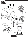
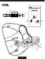
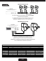
USER’S MANUAL
MANUALE UTENTE
proelgroup.com
FCC COMPLIANCE NOTICE
This device complies with part 15 of the FCC rules. Operation is subject to the
following two conditions:
(1) This device may not cause harmful interference, and
(2) this device must accept any interference received, including interference that
may cause undesired operation.
CAUTION: Changes or modifications not expressly approved by the party
responsible for compliance could void the user’s authority to operate the
equipment.
NOTE: This equipment has been tested and found to comply with the limits for
a Class B digital device, pursuant to part 15 of the FCC Rules. These limits are
designed to provide reasonable protection against harmful interference in a
residential installation. This equipment generates, uses, and can radiate radio
frequency energy and, if not installed and used in accordance with the instruction
manual, may cause harmful interference to radio communications. However, there
is no guarantee that interference will not occur in a particular installation. If this
equipment does cause harmful interference to radio or television reception, which
can be determined by turning the equipment off and on, the user is encouraged to
try to correct the interference by one or more of the following measures:
• Reorient or relocate the receiving antenna.
• Increase the separation between the equipment and receiver.
• Connect the equipment into an outlet on a circuit different from that to which
the receiver is connected.
• Consult the dealer or an experienced radio/TV technician for help.
65.8 mm
2.59"
=
57.2 mm
2.25"
=
Ø 4.5mm / 0.17”
black / nero
red / rosso
FIG. 1
3
65.8 mm
2.59"
=
57.2 mm
2.25"
=
Ø 4.5mm / 0.17”
black / nero
red / rosso
4
FIG. 2
75.0 mm
2.95"
32.0 mm
1.26"
Ø 6 mm / 0.23”
black / nero
red / rosso
FIG. 3
5
CONNECTIONS
hot
cold
ground
INPUT
Balanced male XLR
INPUT (ingresso)
XLR bilanciato maschio
ground
cold
hot
OUTPUT
OUTPUT (uscita)
Balanced female XLR XLR bilanciato femmina
tip - hot
ring - cold
INPUT
Jack (balanced)
INPUT (ingresso)
Jack (bilanciato)
sleeve - ground
tip - hot
cold
INPUT
Jack (unbalanced)
6
FIG. 4
INPUT (ingresso)
Jack (sbilanciato)
ground
CONSTANT VOLTAGE LINE
AUP240L
(for other AVL equipment see AVL system
catalogue at proelgroup.com)
+
-
+
-
+
-
+
-
+
-
100 / 70 V line
The TOTAL POWER of all the speakers must be less or equal
to the power of the amplifier.
La SOMMA delle potenze degli altoparlanti deve essere
inferiore o uguale alla potenza dell’amplificatore.
LOW IMPEDANCE SYSTEM
ACDT90V
(for other AVL equipment see AVL system
catalogue at proelgroup.com)
+ -
L
+ -
L
R
R
- +
- +
Speakers and amplifier power capability must be
approximately the same for the specified impedance.
Altoparlanti e amplificatore devono avere approssimativamente
la stessa potenzaper l’impedenza specificata.
XENIA - TECHNICAL SPECIFICATIONS - SPECIFICHE TECNICHE
Model
Speakers
X30T
HF
LF
3" woofer
X50T
X80T
1" soft dome horn loaded tweeter
5" woofer
8" woofer
X80A
8" woofer
Power
nominal
max
Nominal impedance
Line input
Connections
Power amplifier
Controls
Frequency response (-10 dB)
SPL (1W/1m, 1 kHz)
MAX SPL
Dimensions (mm)
Weight (kg)
15W
30W
8 ohm
70/100 V
Integral connections included in the
bracket (wire terminals)
70/100 V voltage tap selector
8ohm - 8/15/30W power tap selector
100-20k Hz
87 dB
12.5x19.3x12
1.3
30W
60W
8 ohm
70/100 V
Integral connections included in the
bracket (wire terminals)
70/100 V voltage tap selector
8ohm - 12/25/50W power tap selector
80-20k Hz
90 dB
17x28x17.5
2.3
FIG. 5
50W
100W
8 ohm
70/100 V
2 x binding post
70/100 V voltage tap selector
8ohm - 25/50/100W power tap selector
75-20k Hz
91 dB
25x42x25
4.6
COMBO connector (INPUT)
XLR-M connector (LINK)
80+20 W
LEVEL, HI EQ, LO EQ
MIC/LINE selector, GND LIFT
75-20k Hz
113 dB
25x42x25
6.2
7
This marking shown on the product or its literature, indicates that it should not be disposed with other household wastes
at the end of its working life. To prevent possible harm to the enviroment or human health from uncontrolled waste
disposal, please separate this from other types of wastes and recycle it responsibly to promote the sustainable reuse of
material resources. Household users should contact either the retailer where they purchased this product, or their local
government office, for details of where and how they can take this item for environmentally safe recycling. Business users
should contact their supplier and check the terms and conditions of the purchase contract. This product should not be mixed
with other commercial wastes for disposal.
The lightning flash with arrowhead symbol within an equilateral triangle is intended to alert the user to the presence of
uninsulated “dangerous voltage” within the product’s enclosure, that may be of sufficient magnitude to constitute a risk of
electric shock to persons.
The exclamation point within an equilateral triangle is intended to alert the user to the presence of important operating
and maintenance (servicing) instructions in the literature accompanying the appliance.
SAFETY AND PRECAUTIONS
•
CAUTION - Before using this product read carefully the following safety instructions. Take a look of this manual entirely and
preserve it for future reference.
When using any electric product, basic precautions should always be taken, including the following:
– To reduce the risk, close supervision is necessary when the product is used near children.
– Protect the apparatus from atmospheric agents and keep it away from water, rain and high humidity places.
– This product should be site away from heat sources such as radiators, lamps and any other device that generate heat.
– This product should be located so that its location or position does not interfere with its proper ventilation and heating
dissipation.
– Care should be taken so that objects and liquids do not go inside the product.
– The product should be connected to a power supply mains line only of the type described on the operating instructions or
as marked on the product. Connect the apparatus to a power supply using only power cord included making always sure it is in
good conditions.
– WARNING: The mains plug is used as disconnect device, the disconnect device shall remain readily operable.
– Do not cancel the safety feature assured by means of a polarized line plug (one blade wider than the other) or with a earth
connection.
– Make sure that power supply mains line has a proper earth connection.
– Power supply cord should be unplugged from the outlet during strong thunderstorm or when left unused for a long period of
time.
IN CASE OF FAULT
•
–
–
–
–
–
•
In case of fault or maintenance this product should be inspected only by qualified service personnel when:
There is a flaw either in the connections or in the supplied connecting cables.
Liquids have spilled inside the product.
The product has fallen and been damaged.
The product does not appear to operate normally or exhibits a marked change in performance.
The product has been losted liquids or gases or the enclosure is damaged.
Do not operate on the product, it has no user-serviceable parts inside, refer servicing to an authorized maintenance centre.
CE CONFORMITY
• Proel products comply with directive 89/336/EEC (EMC) and following modifications 92/31/EEC and 93/68/EEC, as stated in EN
55103-1 and EN 55103-2 standards and with directive 73/23/EEC (LVD) and following modifications 93/68/EEC, as stated in EN
60065 standard.
• Under the EM disturbance, the ratio of signal-noise will be changed above 10dB.
8
english
PACKAGING, SHIPPING AND COMPLAINT
• This unit package has been submitted to ISTA 1A integrity tests. We suggest you control the unit conditions immediately after
unpacking it.
• If any damage is found, immediately advise the dealer. Keep all unit packaging parts to allow inspection.
• Proel is not responsible for any damage that occurs during shipment.
• Products are sold “delivered ex warehouse” and shipment is at charge and risk of the buyer.
• Damages to unit should be immediately notified to forwarder. Each complaint for manumitted package should be done within
eight days from receipt.
WARRANTY AND PRODUCTS RETURN
• Proel products have operating warranty and comply their specifications, as stated by manufacturer.
• Proel warrants all materials, workmanship and proper operation of this product for a period of two years from the original
date of purchase. If any defects are found in the materials or workmanship or if the product fails to function properly during
the applicable warranty period, the owner should inform about these defects the dealer or the distributor, providing receipt or
invoice of date of purchase and defect detailed description. This warranty does not extend to damage resulting from improper
installation, misuse, neglect or abuse. Proel S.p.A. will verify damage on returned units, and when the unit has been properly
used and warranty is still valid, then the unit will be replaced or repaired. Proel S.p.A. is not responsible for any "direct damage"
or "indirect damage" caused by product defectiveness.
INSTALLATION AND DISCLAIMER
• Proel products have been expressly designed for audio application, with signals in audio range (20Hz to 20kHz). Proel has no
liability for damages caused in case of lack of maintenance, modifications, improper use or improper installation non-applying
safety instructions.
• The installation of these speakers is provided for indoors, in case of use outdoors be sure that the speakers are installed correctly
in a safe location protected from wind, rain and umidity.
• The installation of these speakers is provided for wall mounting by means of specific wall brackets able to support their weight.
Fix the wall bracket to the wall using appropriate fixings.
• Always know the working load limit of the structure supporting the loudspeakers. Always make sure that the fixings minimum
rating is at least five times the actual load, speakers and wall brackets.
• In case of installations of active loudspeakers where is not possible to turn on and off the speakers from their appropriate
switches, we recomend to install switches on the mains lines, for this purpose consult an expert electrician for the exact
dimensioning of wiring.
• Locate the speakers as far away as possible from radio or television receivers or other sensitive equipment. These speakers
have a strong magnetic field which can induce hum and noise into unshielded devices that are located nearby with consequent
deterioration of reception of image and sound.
• Proel S.p.A. declines any liability for damages to objects or persons caused by lacks of maintenance, improper use, installation
not performed with safety precautions and at the state of the art.
POWER SUPPLY AND MAINTENANCE
• Clean only with dry cloth.
• The amplified loudspeakers of Proel have been designed with CLASS I construction and must be connected always to a mains
socket outlet with a proctetive earth connection (the third grounding prong).
• Before connecting the product to the mains outlet make certain that the mains line voltage matches that shown on the rear
of the product, a tolerance of up to ±10% is acceptable.
• Inside the amplified loudspeakers are present special safety devices such as:
Amplifier over-heating protection.
Protection against excessive power applied at each speaker.
• Inside the passive loudspeakers are present special safety devices such as:
Protection against excessive power applied at HF-driver speaker.
• WARNING: THE REPLACEMENT OF FUSES INSIDE THE APPARATUS MUST BE MADE ONLY BY QUALIFIED PERSONNEL.
english
9
Introduction
XENIA is a series of speakers designed specifically for high-profile installed sound applications and featuring
contemporary Italian styling and advanced technical solutions.
All of the models in the XENIA range utilize high-definition dome tweeters and high-efficiency woofers,
providing superior quality, full-range sound for a wide scope of installations where the sound system must
blend perfectly into a stylish environment.
The innovative wall bracket with integral connections and 120” horizontal and vertical rotation, offers
excellent versatility and the fastest installation of its kind.
The three different surface-mount models available suit any kind of installed sound system, from paging and
background music in small-size environments, to full-range sound in bars, department stores and outdoor
venues, through to higher SPL systems in large areas such as shopping malls and airports.
INSTALLATION instructions valid for all models
1. WALL DRILLING
The wall drilling must be done as shown in the drawing for the model to be installed. Always check that the
fixing plugs choosen are suitable to the type of wall and that they can hold up the weight of the speaker
safely. Check also that there is enough space to orientate the loudspeaker in the desired direction.
2. CONNECTION
Connect the speaker to the amplifier following the correct polarity: Red (+) positive / Black (-) negative.
Following the same polarity for the whole audio system is very important for obtaining an optimal acoustical
result.
3. FIXING THE BRACKET TO THE WALL
Make sure that the safety cable is connected to the bracket, then fix the bracket to the wall.
4. SAFETY CABLE LOCKING
Fix the safety cable to the hole on the loudspeaker back panel using the screw provided.
5. SPEAKER MOUNTING
Plug in the speaker to the bracket terminal, then screw in COMPLETELY the locking screw underneath the
cabinet.
ALWAYS MAKE SURE THAT LOUDSPEAKER IS PROPERLY LOCKED TO ITS BRACKET.
6. HORIZONTAL AIMING
Aim the loudspeaker loosening the hex screw shown in the figure: after the correct angle has been set,
tighten back the screw.
7. VERTICAL AIMING
Aim the loudspeaker loosening the hex shown indicated in the figure: after the correct angle has been set,
tighten back the screw.
8. VOLTAGE SETTING
If the loudspeaker is connected to a constant voltage distributed line, set the switch to the correct voltage
(70V is usually the standard for America, 100V is usually the standard for Europe).
Always check that the line power amplifier is set for the same voltage.
9. LINE POWER SETTING OR LOW IMPEDANCE SETTING
Use this switch to set the max power sent to the loudspeaker when it is connected to a constant voltage
line: this setting depends on the max output power of amplifier and on the number of speakers connected,
according to the rule shown in FIG.5.
The same switch can be used for selecting 8 Ω impedance, so the line transformer is excluded and the
loudspeaker can be connected to a low impedance amplifier (see the LOW IMPEDANCE SYSTEM connection
in FIG.5). In this case power capability of speakers and amplifier must be approximately the same for the
specified impedance.
CAUTION: the speaker can be damaged if it is erroneously set to 8 Ω and connected to a distributed
line.
10
english
CONNECTION and OPERATING instructions for X80A
10. MIC/LINE IN (XLR-JACK input)
This is a female combo connector, which accepts a XLR or a JACK plug from almost any type of equipment
with a balanced or unbalanced output. The XLR input is wired as follows:
Pin 1 = shield or ground
Pin 2 = + positive or "hot"
Pin 3 = - negative or "cold"
The JACK input is wired as follows:
Tip = + positive or "hot"
Ring = - negative or "cold"
Sleeve = shield or ground
When connecting an unbalanced signal, wire them as follows:
Pin2 / Tip = + positive or "hot"
Pin 1-3 / Sleeve = shield or ground
NOTE: Whenever possible, use always balanced cables. Unbalanced lines may also be used but may
result in noise over long cable runs. In any case, avoid using a balanced cable for one channel and an
unbalanced one for the other.
11. LINK (XLR output )
This XLR connector is linked directly to the input signal and it is able to re-send the signal to other
speakers.
12. GND LIFT switch
This switch lift the ground of the balanced audio inputs from the earth-ground of the amplifier. If you have
HUM noise problems on one or more speakers try to change the position of these switches.
13. HIGH control
This control gives you up to 6 dB boost or cut at 8 KHz with a "SHELVING" curve shape. Use it to add or
reduce the sound "clarity" and "brightness".
14. LOW control
This control gives you up to 6 dB boost or cut at 100 Hz with a "SHELVING" curve shape. Use it to add or
reduce the sound "punch", or to reduce the low frequency rise when the speaker is set near wall corners or
wall-ceiling corners.
15. LEVEL control
Rotary level control: it attenuates the level of the signal sent to the internal amplifier. The attenuation ranges
from “0” fully closed (the signal is completely attenuated) to “10” fully open.
16. MIC / LINE switch
This switch control adjusts the gain of the XLR input varying the sensitivity between MIC, suited to connect
a microphone, and LINE, suited to connect a device with high level output like a MIXER, a CD player etc.
17. SIGN/LIMIT indicator
GREEN LED illuminates to indicate the presence of the signal at the amplifier input.
RED LED illuminates when the internal amplifier's output is limited. When the RED color LED flashes reduce
the input signal level.
18. ON indicator
GREEN LED: when lighted indicates that the amplifier has been turned on and AC power is available.
19. AC~ socket
Here’s where you plug in your speaker’s mains supply cord. You should always use the mains cord supplied
with the speaker. Be sure your speaker is turned off before you plug the mains supply cord into an electrical
outlet.
20. POWER switch
Speaker is "ON" when the switch is in the "I" position, use this switch to set the speaker power to ON or
OFF.
NOTE: When you shut down your equipment, turn off the speaker first.When powering up, turn on
the speaker last.
english
11
Il marchio riportato sul prodotto o sulla documentazione indica che il prodotto non deve essere smaltito con altri rifiuti
domestici al termine del ciclo di vita. Per evitare eventuali danni all’ambiente si invita l’utente a separare questo prodotto
da altri tipi di rifiuti e di riciclarlo in maniera responsabile per favorire il riutilizzo sostenibile delle risorse materiali. Gli
utenti domestici sono invitati a contattare il rivenditore presso il quale è stato acquistato il prodotto o l’ufficio locale
preposto per tutte le informazioni relative alla raccolta differenziata e al riciclaggio per questo tipo di prodotto. Gli utenti
aziendali sono invitati a contattare il proprio fornitore e verificare i termini e le condizioni del contratto di acquisto. Questo
prodotto non deve essere smaltito unitamente ad altri rifiuti commerciali.
Il simbolo del lampo con freccia in un triangolo equilatero intende avvertire l'utilizzatore per la presenza di "tensioni
pericolose" non isolate all'interno dell'involucro del prodotto, che possono avere una intensità sufficiente a costituire rischio
di scossa elettrica alle persone.
Il punto esclamativo in un triangolo equilatero intende avvertire l'utilizzatore per la presenza di importanti istruzioni per
l'utilizzo e la manutenzione nella documentazione che accompagna il prodotto.
AVVERTENZE PER LA SICUREZZA
• ATTENZIONE - Durante le fasi di uso o manutenzione, devono essere prese alcune precauzioni onde evitare danneggiamenti
alle strutture meccaniche ed elettroniche del prodotto.
Prima di utilizzare il prodotto, si prega di leggere attentamente le seguenti istruzioni per la sicurezza. Prendere visione del
manuale d’uso e conservarlo per successive consultazioni:
– In presenza di bambini, controllare che il prodotto non rappresenti un pericolo.
– Posizionare l’apparecchio al riparo dagli agenti atmosferici e a distanza di sicurezza dall’acqua, dalla pioggia e dai luoghi ad
alto grado di umidità.
– Collocare o posizionare il prodotto lontano da fonti di calore quali radiatori, griglie di riscaldamento e ogni altro dispositivo
che produca calore.
– Collocare o posizionare il prodotto in modo che non ci siano ostruzioni alla sua propria ventilazione e dissipazione di calore.
– Evitare che qualsiasi oggetto o sostanza liquida entri all’interno del prodotto.
– Il prodotto deve essere connesso esclusivamente alla rete elettrica delle caratteristiche descritte nel manuale d’uso o scritte sul
prodotto, usando esclusivamente il cavo rete in dotazione e controllando sempre che sia in buono stato, in particolare la spina
e il punto in cui il cavo esce dal prodotto.
– ATTENZIONE: Se il cavo rete viene scollegato dall'apparecchio per spegnerlo, il cavo rete rimarrà operativo in quanto la sua
spina è ancora collegata alla rete elettrica.
– Non annullare la sicurezza garantita dall'uso di spine polarizzate o con messa a terra.
– Fare attenzione che il punto di alimentazione della rete elettrica sia dotato di una efficiente presa di terra.
– Disconnettere il prodotto dalla rete elettrica durante forti temporali o se non viene usato per un lungo periodo di tempo.
IN CASO DI GUASTO
•
–
–
–
–
–
•
In caso di guasto o manutenzione questo prodotto deve essere ispezionato da personale qualificato quando:
Ci sono difetti sulle connessioni o sui cavi di collegamento in dotazione.
Sostanze liquide sono penetrate all’interno del prodotto.
Il prodotto è caduto e si è danneggiato.
Il prodotto non funziona normalmente esibendo una marcato cambio di prestazioni.
Il prodotto perde sostanze liquide o gassose o ha l’involucro danneggiato.
Non intervenire sul prodotto. Rivolgersi a un centro di assistenza autorizzato Proel.
CONFORMITÀ CE
• I Prodotti Proel sono conformi alla direttiva 89/336/EEC (EMC) e successive modifiche 92/31/EEC e 93/68/EEC, secondo gli
standard EN 55103-1 ed EN 55103-2 ed alla direttiva 73/23/EEC (LVD) e successive modifiche 93/68/EEC, secondo lo standard EN
60065.
• Se sottoposto a disturbi EM, il rapporto segnale-rumore può essere superiore a 10dB.
12
italiano
IMBALLAGGIO, TRASPORTO E RECLAMI
• L’imballo è stato sottoposto a test di integrità secondo la procedura ISTA 1A. Si raccomanda di controllare il prodotto subito
dopo l’apertura dell’imballo.
• Se vengono riscontrati danni informare immediatamente il rivenditore. Conservare quindi l’imballo completo per permetterne
l’ispezione.
• Proel declina ogni responsabilità per danni causati dal trasporto.
• Le merci sono vendute “franco nostra sede” e viaggiano sempre a rischio e pericolo del distributore.
• Eventuali avarie e danni dovranno essere contestati al vettore. Ogni reclamo per imballi manomessi dovrà essere inoltrato entro
8 giorni dal ricevimento.
GARANZIE E RESI
• I Prodotti Proel sono provvisti della garanzia di funzionamento e di conformità alle proprie specifiche, come dichiarate dal
costruttore.
• La garanzia di funzionamento è di 24 mesi dopo la data di acquisto. I difetti rilevati entro il periodo di garanzia sui prodotti
venduti, attribuibili a materiali difettosi o difetti di costruzione, devono essere tempestivamente segnalati al proprio rivenditore
o distributore, allegando evidenza scritta della data di acquisto e descrizione del tipo di difetto riscontrato. Sono esclusi dalla
garanzia difetti causati da uso improprio o manomissione. Proel SpA constata tramite verifica sui resi la difettosità dichiarata,
correlata all’appropriato utilizzo, e l’effettiva validità della garanzia; provvede quindi alla sostituzione o riparazione dei prodotti,
declinando tuttavia ogni obbligo di risarcimento per danni diretti o indiretti eventualmente derivanti dalla difettosità.
INSTALLAZIONE E LIMITAZIONI D’USO
• I Prodotti Proel sono destinati esclusivamente ad un utilizzo specifico di tipo sonoro: segnali di ingresso di tipo audio (20Hz20kHz). Proel declina ogni responsabilità per danni a terzi causati da mancata manutenzione, manomissioni, uso improprio o
installazione non eseguita secondo le norme di sicurezza.
• L'installazione di questi altoparlanti è prevista per uso interno, in caso di utilizzo all'esterno assicurarsi che gli altoparlanti siano
installati correttamente in un luogo sicuro e protetto dal vento, pioggia e umidità.
• L'installazione di questi altoparlanti è prevista a parete tramite specifici supporti in grado di sostenere il proprio peso. Fissare i
supporti da parete usando solo fissaggi appropriati e specifici per quella parete.
• Non superare il limite di carico della struttura che sosterrà gli altoparlanti. Assicurarsi che tutti i fissaggi di sostegno siano in
grado di sopportare un peso almeno 5 volte superiore al carico degli altoparlanti inclusi i supporti.
• Nel caso di installazioni sospese di altoparlanti attivi in cui non sia possibile l'uso dei singoli interruttori degli altoparlanti per
l'accensione e lo spegnimento dei medesimi, si raccomanda l'installazione di interruttori sulle linee di alimentazione della rete
elettrica, a tale proposito consultare un esperto elettricista per il corretto dimensionamento dell'impianto elettrico.
• Installare questi altoparlanti il più lontano possibile da radioricevitori e televisori. Un altoparlante installato in prossimità di
questi apparati può causare interferenza e rumore con conseguente degrado della ricezione di immagini e suoni.
• Proel declina ogni responsabilità per danni a terzi causati da mancata manutenzione, manomissioni, uso improprio o
installazione non eseguita secondo le norme di sicurezza e a regola d'arte.
ALIMENTAZIONE E MANUTENZIONE
• Pulire il prodotto unicamente con un panno asciutto.
• Controllare periodicamente che le aperture di raffredamento non siano ostruite da accumuli di polvere, provvedere alla
rimozione della polvere mediante un pennello o aria compressa.
• Gli altoparlanti amplificati della Proel sono costruiti in CLASSE I e prevedono sempre il collegamento mediante presa di corrente
con terminale di terra di protezione (terzo terminale di terra).
• Prima di collegare l'apparecchio alla presa di corrente, accertatevi che la tensione di rete corrisponda a quella indicata sul retro
dell’apparato, è consentito un margine del ±10% rispetto al valore nominale.
• Negli altoparlanti amplificati sono presenti anche i seguenti dispositivi di sicurezza:
protezioni termiche dell'amplificatore.
protezioni alla potenza erogata in eccesso ai singoli altoparlanti.
• Negli altoparlanti passivi sono presenti anche i seguenti dispositivi di sicurezza:
protezione alla potenza erogata in eccesso all'altoparlante driver delle alte frequenze.
• LA SOSTITUZIONE DI FUSIBILI ALL'INTERNO DELL'APPARATO È CONSENTITO ESCLUSIVAMENTE A PERSONALE QUALIFICATO.
italiano
13
Introduzione
XENIA è una serie di diffusori progettati in modo specifico per installazioni fisse di alto profilo, utilizzando
design Italiano di alto livello e soluzioni tecniche avanzate.
Tutti i modelli XENIA utilizzano tweeter a cupola ad alta definizione e woofer ad elevata efficienza, per
garantire prestazioni acustiche superiori e un suono full-range di elevata qualità, per un'ampia gamma di
installazioni in cui il sistema di diffusione deve fondersi perfettamente con un'ambiente elegante.
L'innovativa staffa di fissaggio con connessioni integrate e possibilità di rotazione di 120° in orizzontale e
verticale, offre la massima versatilità e velocità di installazione.
I tre diversi modelli surface-mount disponibili sono adatti a qualsiasi applicazione in sistemi sonori installati,
dalla diffusione di annunci e musica di sottofondo in piccoli ambienti, ad un suono full-range in bar,
supermercati e ambienti aperti, fino a sistemi ad elevata pressione sonora in spazi di grandi dimensioni
come centri commerciali ed aeroporti.
Istruzioni di INSTALLAZIONE valide per tutti i modelli
1. FORATURA PARETE
Eseguire la foratura della parete secondo il disegno per il modello da installare. Accertarsi che i tasselli scelti
siano adatti al tipo di parete e siano in grado di sostenere il peso dell'altoparlante in sicurezza.
Accertarsi che l'altoparlante disponga dello spazio necessario al suo orientamento.
2. COLLEGAMENTO
Collegare l'altoparlante all'impianto rispettando la polarità indicata: Rosso (+) positivo / Nero (-) negativo.
Rispettare la medesima polarità in tutto il sistema di amplificazione è molto importante al fine di ottenere
un comportamento acustico ottimale.
3. MONTAGGIO SUPPORTO ALLA PARETE
Assicurarsi che il cavo di sicurezza sia fissato al supporto ed avvitare il supporto alla parete.
4. FISSAGGIO CAVO DI SICUREZZA
Fissare il cavo di sicurezza nel foro predisposto sull'altoparlante usando la vite in dotazione.
5. FISSAGGIO ALTOPARLANTE
Inserire l'altoparlante nel supporto, quindi avvitare accuratamente la vite di blocco posta al di sotto dell'
altoparlante.
ACCERTARSI SEMPRE CHE L'ALTOPARLANTE SIA CORRETTAMENTE BLOCCATO AL SUPPORTO.
6. ORIENTAMENTO ORIZZONTALE
Orientare correttamente l'altoparlante allentando la vite ad esagono indicata, una volta determinato l'angolo
corretto stringerla nuovamente.
7. ORIENTAMENTO VERTICALE
Orientare correttamente l'altoparlante allentando la vite ad esagono indicata, una volta determinato l'angolo
corretto stringerla nuovamente.
8. IMPOSTAZIONE LINEA
Se l'altoparlante è collegato ad una linea distribuita a tensione costante, accertarsi che il selettore sia
posizionato sulla corretta tensione (70V è solitamente usato come standard in America, 100V è solitamente
usato come standard in Europa).
Accertarsi sempre che l'amplificatore collegato sulla linea sia impostato per la medesima tensione.
9. IMPOSTAZIONE POTENZA LINEA O BASSA IMPEDENZA
Tramite questo selettore è possibile impostare la potenza da inviare all'altoparlante quando questo è
collegato ad una linea distribuita. L'impostazione è in funzione della potenza dell'amplificatore e del numero
di altoparlanti collegati secondo la formula riportata in FIG.5.
Lo stesso selettore può essere utilizzato per selezionare l'impedenza di 8 Ω, in modo da escludere il
trasformatore di linea e collegare l'altoprlante ad un amplificatore a bassa impedenza (vedi LOW IMPEDANCE
SYSTEM nella FIG.5). In tal caso la scelta della potenza dell'amplificatore deve approssimativamente
coincidere con la potenza degli altoparlanti impiegati per l'impedenza specificata.
ATTENZIONE: se un altoparlante viene erroneamente impostato su 8 Ω e collegato ad una linea
distribuita si può causare la rottura dell'altoparlante stesso.
14
italiano
Istruzioni di COLLEGAMENTO ed USO modello X80A
10. MIC/LINE IN (ingresso microfono/linea combo XLR-JACK)
Connettore combinato che accetta un XLR o un JACK maschio da praticamente tutti gli apparecchi con cavo
bilanciato o sbilanciato. Le terminazioni dell' ingresso XLR sono:
Pin 1 = schermo o massa
Pin 2 = + positivo o "caldo"
Pin 3 = - negativo o "freddo"
Le terminazioni dell' ingresso JACK sono le seguenti:
Tip (punta) = + positivo o "caldo"
Ring (anello) = - negativo o "freddo"
Sleeve (manicotto) = schermo o massa
Quando si collega un segnale sbilanciato, sono le seguenti:
Pin2 / Tip (punta) = + positivo o "caldo"
Pin 1-3 / Sleeve (manicotto) = schermo o massa
NOTA: Qualora possibile, usare sempre cavi bilanciati. Cavi sbilanciati possono essere ugualmente
usati ma potrebbero dare problemi di rumore se molto lunghi. In ogni caso, evitate di usare un cavo
bilanciato per un canale e uno sbilanciato per l’altro.
11. LINK (rilancio segnale di ingresso XLR)
È un connettore maschio XLR, collegato direttamente al segnale di ingresso e quindi in grado di rilanciare
il segnale ad altri altoparlanti.
12. GND LIFT (interruttore sollevamento massa)
Questo interruttore solleva la massa degli ingressi audio bilanciati dalla massa-terra dell'amplificatore. Se si
hanno problemi di ronzio su uno o più altoparlanti provare a cambiare la posizione di questi interruttori.
13. HIGH (controllo alti)
Questo controllo permette di guadagnare o attenuare fino a 6 dB a 8 KHz con una curva di tipo "SHELVING".
Da usarsi per aumentare o ridurre la "chiarezza" o "brillanza" del suono.
14. LOW (controllo bassi)
Questo controllo permette di guadagnare o attenuare fino a 6 dB a 100 Hz con una curva di tipo "SHELVING".
Da usarsi per aumentare o ridurre il "vigore" del suono, o per ridurre l'aumento delle basse frequenze
quando l'altoparlante è posizionato vicino a due muri ad angolo o vicino al soffitto.
15. LEVEL (controllo di livello ingresso)
Controllo di livello rotativo: attenua il livello del segnale inviato all'amplificatore interno, l' attenuazione
varia tra completamente chiuso “0” a completamente aperto “10”.
16. MIC / LINE (selettore ingresso linea / microfono)
Questo controllo regola il guadagno dell'ingresso XLR variando la sensibilità tra MIC, adatta a collegare
direttamente un microfono, e LINE, adatta a collegare una apparecchiatura con uscita di livello elevato quale
un MIXER, un lettore CD, etc.
17. SIGN/LIMIT (indicatore di segnale e clip limiter)
LED VERDE che si accende per indicare la presenza del segnale sull'ingresso dell'amplificatore.
LED ROSSO che si accende quando l'uscita dell'amplificatore interno è limitata. Quando questo LED
lampeggia in rosso ridurre il segnale di ingresso.
18. ON (indicatore di accensione)
LED VERDE: quando illuminato indica che l'altoparlante è stato acceso e l'alimentazione AC è disponibile.
19. AC~ (presa di alimentazione di rete)
In questa presa va inserito il cavo di alimentazione di rete dell'altoparlante. Si raccomanda di utilizzare
esclusivamente il cavo di alimentazione in dotazione all'altoparlante. Accertatevi che l'altoparlante sia
spento prima di inserire il cavo di alimentazione nella presa di corrente.
20. POWER (interruttore di accensione)
L'altoparlante è acceso "ON" quando l'interruttore è nella posizione "I". Agite su questo tasto per accendere
o spegnere l'altoparlante.
NOTA: Quando si spegne l'impianto sonoro, spegnere per primi gli altoparlanti. Quando si accende
l'impianto sonoro, accendere gli altoparlanti per ultimi.
italiano
15
PROEL S.p.A.
(World Headquarters - Factory)
Via alla Ruenia, 37/43
64027 Sant’Omero (TE) - ITALY
Tel. +39 0861 81241
Fax +39 0861 887862
proelgroup.com