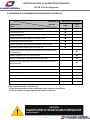
1
INSTALLATION & OPERATION MANUAL U125 Series Engines TABLE OF CONTENTS ABOUT THIS MANUAL …………………………………………………….………………… 3 SAFETY PRECAUTIONS…………………………………………………………………… 4 5 APPROXIMATE CONVERSIONS FROM STANDARD…………………………………….. CHAPTER 1 ENGINE OVERVIEW ……………………………………………………….. 1. ENGINE COMPONENTS ………………………………………………… 2. ENGINE SUSPENSION……..…………………………………………… 3. ENGINE IDENTIFICATION ………………………………………….….. 4. SCHEMATIC DIAGRAM OF COMMON RAIL DIESEL ENGINE …… 5. TECHNICAL DATA ……………………………………………...…..…… 6. PERFORMANCE CURVE ……………………………………………..… 7. BELT LAYOUT & ENGINE DIMENSIONS……….…………………… 6 6 7 8 10 11 13 14 CHAPTER 2 ENGINE MOUNT SYSTEM .……………………………………………… 1. ENGINE MOUNTING REQUIREMENTS ………………………....….… 2. MOUNT DIMENSIONS …………………………………………..…….… 3. ENGINE MOUNT TOOL FOR STERNDRIVE MODEL ………….…… 16 16 16 17 CHAPTER 3 COOLING & EXHAUST SYSTEM …………………………………….…… 18 1. SCHEMATIC DIAGRAM OF ENGINE COOLING CIRCUIT ……….… 18 2. THE FLOW OF SEAWATER ……………………………….……….…… 19 2.1 WATER PICKUP …………………………………..……….…… 19 2.2 SEAWATER STRAINER ………………………..……….……. 19 2.3 SEAWATER PUMP ……………………………..……………… 20 2.4 SEAWATER DRAIN …………………………..……………….. 22 3. THE FLOW OF ENGINE COOLANT …………………………….……… 23 3.1 ENGINE COOLANT …………………………………………………..… 25 3.2 REMOVING AIR BUBBLE ………………………………………….…... 25 3.3 CABIN HEATER CONNECTION …………………………………..…… 26 4. EXHAUST SYSTEM ……………………………………………………… 27 CHAPTER 4 FUEL SYSTEM ………………………………………………………….…… 28 1. THE FLOW OF FUEL ……………………………….……..……………… 28 2. LOW PRESSURE FUEL LINE …………………....…………….…………29 3. ACCELERATION SENSOR AND CONTROL LEVER ………………… 30 4. RECOMMENDED FUEL QUALITY ………………....…………….………31 5. DRAINING WATER FROM FUEL FILTER ……………………………… 31 CHAPTER 5 AIR INTAKE SYSTEM …………………………………………………………31 1. ENGINE ROOM VENTILATION …………………………….…….…… 32 2. AIR FILTER MAINTENANCE ……………………………….…..……… 33 CHAPTER 6 LUBRICATION SYSTEM ………………………………………………….… 33 1. ENGINE OIL LEVEL CHECKS ………………………………….……… 33 2. RECOMMENDED OIL QUALITY ………………………….…….....…… 34 3. ENGINE OIL EXTACTION PUMP ………………………..………..…… 34 4. OIL FILTER REPLACEMENT …………………………………….……… 35 -1- INSTALLATION & OPERATION MANUAL U125 Series Engines TABLE OF CONTENTS CHAPTER 7 ELECTRICAL SYSTEM …………………………………………………… 1. BATTERY CABLE CONNECTIONS …………………………….......… 2. BATTERY CHECKS ………………………………………………….… 3. FUSE AND RELAY ………………………………………………….…… 35 35 36 37 CHAPTER 8 INSTRUMENT SYSTEM ……………………...…………………………… 1. INSTRUMENTS CONNECTION …………..………………………...… 2. CUT-OUT FOR GAUGE ……………………...……………………...… 3. CUT-OUT FOR EOI SYSTEM …………………..………………….…… 39 39 42 42 CHAPTER 9 EOI SYSTEM …………………………………………..………………….. 43 1. OVERVIEW OF EOI SYSTEM ……………………..…………………..… 43 1.1 INFORMATION LCD ITEM ……………………...……………...… 43 1.2 SWITCHES ………………………………………......…………..…. 44 1.3 ALARM LAMPS ………………………………………..………...… 44 2. EOI CONNECTIONS ………………………………………......……..… 45 3. EOI PIN ASSIGNMENT …………..………………………………........ 46 4. NEUTRAL SWITCH AND DUAL EOI CONNECTION …………….… 48 5. TRIM WIRING CONNECTION DIAGRAM ………………………...… 49 6. G-SCAN……………………………………………………………..……. 50 7. ALARM AND DTC(DIAGNOSIS TROUBLE CODE) …………………. 51 7.1 ALARM AND DTC(DIAGNOSIS TROUBLE CODE) ……………. 51 7.2 DTC(DIAGNOSIS TROUBLE CODE) LIST………….…………… 54 CHAPTER 10 ANTI CORROSION SYSTEM ……………………………………………. 59 CHAPTER 11 ENGINE OPERATION …………………………………………………..…. 1. ENGINE ON/OFF ……………………………………………………….… 2. ENGINE BRAKE IN……………………………………………………… 3. EMERGENCY STOP …………………..…………………………….…… 60 60 61 62 CHAPTER 12 ENGINE STORAGE …………………………………………………..…… 63 WINTER STORAGE…………………………………….…………………. 64 CHAPTER 13 MAINTENANCE …………………………………………………………..… 1. THE INITIAL RUNNING CHECK..……………………………….……… 2. MAINTENANCE SCHEDULE …………………………………..……… 3. STERNDRIVE & TRANSMISSION MAINTENANCE SCHEDULE …. 4. MAINTENANCE LOG…………………………………………………… 65 65 66 66 67 CHAPTER 14 TROUBLESHOOTING GUIDE …………………………………………… 69 CHAPTER 15 WARRANTY ………………………………………………………………… 71 WARRANTY REGISTRATION CARD ……………………………..……… 76 -2- INSTALLATION & OPERATION MANUAL U125 Series Engines ABOUT THIS MANUAL This engine installation and operation manual is provided as guidance for the installation of Hyundai SeasAll engine in a boat, and to describe engine operation. Its purpose is to provide technical information to aid in performing an effective engine installation so as to achieve both maximum performance and service life. For information on installation, operation and maintenance of the ZF Marine Transmissions and Sterndrive Bravo Models, please see the separate booklets included in the original packaging of your Hyundai SeasAll purchase. Hyundai SeasAll is committed to making clear and accurate information available for those who maintain, own and repair the U125 Series engines. Hyundai SeasAll values your input regarding revisions and additional information for our manuals. The manufacturer is not liable for any damages or losses caused by faulty installation, wrong handling of the equipment and/or deficient maintenance. The operator is responsible for the correct and safe operation of the engine and safety of its occupants and general public. It is strongly recommended that each operator read and understand this manual before installing and operating the engine. This manual as well as safety labels posted on the engine use the following safety alerts to draw your attention to special safety instructions that should be followed. WARNING DEVIATION FROM INSTALLATION INSTRUCTIONS AND OPERATION GUIDELINES MAY LEAD TO PERSONAL INJURY OR DEATH TO OPERATORS AND NEARBY PERSONNEL. CAUTION DEVIATION FROM INSTALLATION INSTRUCTIONS AND OPERATION GUIDELINES MAY LEAD TO IMPROPER OPERATION, DAMAGE OR DESTRUCTION OF THE ENGINE. -3- INSTALLATION & OPERATION MANUAL U125 Series Engines SAFETY PRECAUTIONS • Read and understand this operator’s manual HOT SURFACES AND FLUIDS as well as other information supplied by Hyundai SeasAll for safe use of these • There is always a risk of burns when working with a hot engine. Be aware of hot parts like the turbocharger system, the exhaust system, hot coolant hoses, etc. Wait until the engine is fully cool to do inspection and maintenance. products. Be sure to check your engine regularly. • Do not use the engine for a purpose other than what is intended by Hyundai SeasAll. Do not modify the performance of the supplied engine without the express permission of Hyundai SeasAll. This can be dangerous, can shorten the life of your engine and can invalidate your warranty. REFUELING • Refuel only after the engine completely stops. • Use only the recommended fuel. The wrong grade of fuel can cause operating problems, can cause the engine to stop and can cause engine damage. • Original and genuine parts supplied from Hyundai SeasAll must be used for inspections and maintenance. Hyundai • Pay special attention to safe practices when refueling. SeasAll does not guarantee any damage caused by the use of imitation parts. PAINT DAMAGE • Engine inspection and maintenance should • Damage of the engine or parts paint during maintenance and inspection can cause corrosion. Any damage must be repainted after inspection and maintenance. be carried out by properly trained and factory approved service engineers. • The engine should be inspected if the electronic engine control unit shuts down the engine. WELDING ON ENGINE • Welding directly on the engine block can cause damage to the engine control systems. The ECU and related electronic devices must be disconnected and removed if unavoidable welding is needed. . -4- INSTALLATION & OPERATION MANUAL U125 Series Engines APPROXIMATE CONVERSIONS FROM STANDARD LENGTH AREA SYMBOL MULTIPLY BY SYMBOL SYMBOL MULTIPLY BY SYMBOL mm 0.039 inch inch 25.4 mm cm 0.4 inch inch 2.54 cm m 3.28 ft ft 0.3048 m mm2 0.0016 in2 in2 645.2 mm2 ft2 0.093 m2 AREA m2 10.764 ft2 cm3 0.061 in³ in³ 16.388 cm3 mL 0.06 in3 in3 16 mL 61.023 in³ in³ 0.016 Ldm3 Ldm3 0.22 imp.gallon imp.gallon 4.545 Ldm3 Ldm3 0.264 U.S.gallon U.S.gallon 3.785 Ldm3 m3 0.76 yd3 yd3 1.3 m3 m3 35.315 ft³ ft³ 0.028 m3 kgf 2.204 lbf lbf 0.453 kgf lbf 4.448 N Ldm VOLUME LENGTH 3 FORCE FORCE N 0.224 o TEMP. lbf F=9/5x℃+32 o TEMP. C=5/9x(℉-32) Bar 14.5 psi psi 0.068 Bar MPa 145 psi psi 0.0068 MPa Pa 0.102 mmWc mmWc 9.807 Pa PRESSURE TORQUE VOLUME PRESSURE Pa 0.004 inWc inWc 249.098 Pa KPa 4 inWc inWc 0.249 KPa mWg 39.37 inWc inWc 0.025 mWg Nm 0.738 lbf ft lbf ft 1.356 Nm kg 2.205 lb lb 0.454 kg TORQUE WEIGHT WEIGHT kg 35.273 oz oz 0.028 kg kJ/kWh 0.43 BTU/lb BTU/lb 2.326 kJ/kWh MJ/kg 430 BTU/lb BTU/lb 0.0023 MJ/kg kJ/kg 0.24 Kcal/kg Kcal/kg 4.184 kJ/kg ENERGY kJ/kg 0.697 BTU/hph ENERGY BTU/hph 1.435 kJ/kg FUEL CONSUMP. g/kWh 0.736 g/hph g/hph 1.36 g/kWh g/kWh 0.0016 lb/hph FUEL CONSUMP. lb/hph 616.78 g/kWh FLOW RATE (GAS) m3/h 0.588 ft³/min FLOW RATE (GAS) ft³/min 1.699 m3/h FLOW RATE (LIQUID) m3/h 4.403 US gal/min FLOW RATE (LIQUID) US gal/min 0.2271 m3/h m/s 3.281 ft/s ft/s 0.3048 m/s kph 0.539 knots knots 1.852 kph WORK WORK SPEED SPEED mph 0.869 knots knots 1.1508 mph kph 0.62 mph mph 1.61 kph -5- INSTALLATION & OPERATION MANUAL U125 Series Engines CHAPTER 1 ENGINE OVERVIEW 1.ENGINE COMPONENTS 1. 2. 3. 4. 5. ECU Box Engine Oil Cap Engine Oil Filter Seawater Pump Intercooler Engine Oil Gauge Acceleration Lever Sensor Fuel Filter VGT Alternator Oil Extraction Pump Air Filter Engine Oil Exchange Button Engine Emergency Stop Button Injector Shift Plate Turbo Heat Protector Belt-Drive Coolant Expansion Tank -6- INSTALLATION & OPERATION MANUAL U125 Series Engines 2.ENGINE SUSPENSION • To lift the engine, first remove the engine cover. You will find two engine eyes (see figure) • To avoid engine damage, take care that engine lift chains or belts do not hit or touch surrounding parts during engine lifting. -7- INSTALLATION & OPERATION MANUAL U125 Series Engines 3.ENGINE IDENTIFICATION Engine identification is affixed to the engine block and the ECU box (see figure). SERIAL NUMBER ON THE ENGINE BLOCK • ENGINE NAME PLATE -8- -9- return High pressure pump Fuel tank Water sensor in fuel Fuel temperature sensor Pump pressure regulator valve Main fuel filter return Coolant temperature sensor Glow plug Injector ECU Actuator Sensor Crankshaft position sensor Cam Position Sensor return Rail pressure sensor Common rail Air filter Fuel feed (low) Fuel return Fuel feed (high) Vacuum modulator VGT actuator Intercooler Boost pressure & air temp sensor return pressure limit valve Accel position sensor INSTALLATION & OPERATION MANUAL U125 Series Engines 4.SCHEMATIC DIAGRAM OF COMMON RAIL DIESEL ENGINE INSTALLATION & OPERATION MANUAL U125 Series Engines 5.TECHNICAL DATA U125S Engine type U125P U125J 4-stroke, 16-valve After-cooled, direct-injection, water cooling Output ps (kW) 125ps (93) rpm at full load 4000 Cylinders In-line 4 Ignition sequence 1-3-4-2 Displacement [cm3] 1,582 Bore [mm] 77.2 Stroke [mm] 84.5 Compression ratio 17.3 : 1 Max. torque [kgm] @ speed [rpm] 26.3 23.5 2000 3700 Injection system Common rail direct injection Diesel fuel at least CN 51 as per DIN EN 590 Intake air pressure (abs. bar) @ speed [rpm] 2.5 bar @ 4000 rpm Coolant quantity (liter) 5.5 Coolant cap opening pressure (bar) 1.1 Engine oil (liter) 5.7 Engine oil pressure (bar) 2~3 at 1800rpm, 100 ℃(oil temp.) Exhaust gas pressure (kPa) Max. 45 Alternator [A] 130 Engine diagnosis Yes Weight (kg) 220 Battery capacity (AH) 12V, 150AH recommended Thermostat opening temp. (℃) 85 (starting to open), 95 (fully open) Idle rpm warmed up (rev/min) 730 Permissible eng. oil temp (℃) 135 Permissible eng. coolant temp (℃) 105 Propulsion system Sterndrive -10- Shaftdrive Waterjet INSTALLATION & OPERATION MANUAL U125 Series Engines 6.PERFORMANCE CURVE U125S & U125P MODEL Torque *BSFC : Brake Specific Fuel Consumption -11- *FC : Fuel Consumption INSTALLATION & OPERATION MANUAL U125 Series Engines U125J MODEL *BSFC : Brake Specific Fuel Consumption -12- *FC : Fuel Consumption INSTALLATION & OPERATION MANUAL U125 Series Engines 7.BELT LAYOUT & ENGINE DIMENSIONS V-RIBBED BELT LAYOUT Bobtail Front view Side view [for sterndrive] Side view [for shaftdrive] Side view [for waterjet with bearing housing] -13- INSTALLATION & OPERATION MANUAL U125 Series Engines MerCruiser Bravo One X Diesel Side view Front view ZF 25 A Front view Side view -14- INSTALLATION & OPERATION MANUAL U125 Series Engines ZF 45 A Front view Side view Front view Side view ZF 45 C -15- INSTALLATION & OPERATION MANUAL U125 Series Engines CHAPTER 2 ENGINE MOUNT SYSTEM 1.ENGINE MOUNTING REQUIRMENTS • The mounts must be strong enough to carry the loads applied by the weight and power of the engine. It also must be stiff enough that the engine does not sag or move too much when power is applied. • The mounts must position the engine at the correct height and angle so that the engine’s thrust line suits the boat. 2.ENGINE MOUNT DIMENSIONS CAUTION USE ONLY THE ORIGINAL HYUNDAI SEASALL ENGINE MOUNTS THAT WERE SUPPLIED WITH THE INITIAL PURCHASE. AFTER INSTALLATION AND ALIGNMENT OF THE ENGINE, MAKE SURE THAT NO RESIDUAL TENSION EXISTS IN THE DRIVETRAIN. -16- INSTALLATION & OPERATION MANUAL U125 Series Engines 3.ENGINE MOUNT TOOL FOR STERNDRIVE MODEL (O) The genuine alignment tool of Hyundai-Seasall(Five step) (X) The alignment tool of MerCruiser(Four step) Mount hole for U125 model Mount hole for D170 and D150 model Mount hole for S250 and S220 model CAUTION IT IS ESSENTIAL THAT THE ENGINE BED IS PERFECTLY FLAT BEFORE USING ENGINE MOUNT TOOL. FOR INFORMATION ON INSTALLATION OF THE STERNDRIVE BRAVO MODELS, PLEASE SEE THE SEPARATE BOOKLETS INCLUDED IN THE ORIGINAL PACKAGING OF YOUR HYUNDAI SEASALL PURCHASE. HYUNDAI SEASALL ENGINES MUST BE USE THE GENUINE ALIGNMENT TOOL OF HYUNDAI SEASALL OTHER THE DRIVE COUPLER WILL BE DAMAGED. -17- INSTALLATION & OPERATION MANUAL U125 Series Engines CHAPTER 3 COOLING & EXHAUST SYSTEM 1.SCHEMATIC DIAGRAM OF ENGINE COOLING CIRCUIT AIR CABIN HEATER CONNECTOR AIR FILTER EX-MANIFOLD ENG.OIL COOLER TURBO CHARGER Pc THERMOSTAT COOLANT PUMP IN-MANIFOLD HEAT EXCHANGER EXPANSION TANK OIL COOLER OIL INTERCOOLER Ps SEAWATER SEA WATER PUMP INTAKE AIR EXHAUST AIR COOLANT ( THERMOSTAT CLOSED & OPENED ) SEAWATER COOLANT (THERMOSTAT OPENED ) -18- INSTALLATION & OPERATION MANUAL U125 Series Engines 2.SEAWATER FLOW – OPEN COOLING CIRCUIT Water strainer ← Water valve ← Water pickup ↓ ① Seawater pump ↓ ② Intercooler ↓ ③ Transmission oil cooler ↓ ④ Heat exchanger ↓ ⑤ Exhaust elbow ↓ Sea water 2.1.WATER PICKUP • Water pickup should be installed in an area where it won’t pick up air bubbles and will access clean water during all phases of the engine operation. • For use in sterndrive models, please see the section “Installing Sterndrive Seawater Pickup” of the BRAVO MODELS INSTALLATION MANUAL, included in the original packaging. • For further safety, you can use an additional transom or bottom mounted clamshell-type water pickup. 2.2.WATER STRAINER • Strainer should be located in an area where it will be easily accessible for periodic seawater flow inspection and cleaning. • The size of strainer must be of sufficient capacity to pass the seawater (a flow rate over 150 liters per minute flow rate). • Strainer must be installed after water inlet valve in order to allow user to shut off seawater when cleaning strainer filter. CAUTION IF THE SEAWATER STRAINER IS NOT PROPERLY ASSEMBLED, AIR CAN BE SUCKED INTO THE COOLING CIRCUIT, DISTURBING THE VACUUM PROCESS. THIS CAN CAUSE THE ENGINE TO OVERHEAT. -19- INSTALLATION & OPERATION MANUAL U125 Series Engines CLEAN STRAINER FILTER • Stop the engine and close the water valve. • Remove the filter cap. • Remove the filter element, flush it thoroughly with clean water or compressed air. • Insert the cleaned filter element and screw on the filter cap. • Check the cap and the gasket for correct seating and sealing. • Open the water valve. • Start the engine and check if there is water leakage. 2.3.SEAWATER PUMP • The internal diameter of hose connected to seawater pump inlet should be 32mm. • The cross section of the hose may shrink due to inlet pressure drop. Therefore, the hose from water pickup in the boat’s hull to the seawater pump inlet should be as short as possible and must be made of steel wire reinforced material. • The seawater pump impeller must be checked periodically and replaced if necessary. CAUTION IF ASSEMBLY IS NOT CONDUCTED PROPERLY, AIR CAN BE SUCKED IN, DISTURBING THE VACUUM PROCESS. THIS CAN CAUSE THE ENGINE TO OVERHEAT. -20- INSTALLATION & OPERATION MANUAL U125 Series Engines CHECKING SEA WATER PUMP & IMPELLER • Stop the engine and close the water valve. • Remove the impeller housing cover. • Remove the impeller from inside the seawater pump. • Check the condition of impeller and bushing. • Apply soapy water to impeller when assembling, and reassemble towards rotation direction. • Replace of the O-ring on the impeller housing cover. • Open the water valve. • Start the engine and check if there is water leakage. CAUTION DO NOT RUN THE ENGINE WITHOUT SEAWATER. THE SEAWATER PUMP IMPELLER WILL BE DAMAGED. BEFORE STARTING THE ENGINE, BE SURE TO SUPPLY SEAWATER TO THE PASSAGES. CAUTION IMPELLER DAMAGE MAY OCCUR IF APPROPRIATE TOOLS ARE NOT USED WHEN REMOVING THE IMPELLER. MAKE SURE TO CHECK ORING CONDITION AFTER SEAWATER PUMP REASSEMBLY. CAUTION DO NOT INSTALL ADDITIONAL DEVICES WHICH COULD OBSTRUCT THE FLOW OF SEAWATER. THIS CAN CAUSE THE ENGINE TO OVERHEAT. -21- INSTALLATION & OPERATION MANUAL U125 Series Engines 2.4 SEA WATER DRAIN HEAT EXCHANGER • Remove anode, then please let the sea water drain. • Removing and Inspection procedure 1. Remove the anode plugs on the heat exchanger (A) and the intercooler (B). 2. Squeeze the hose (C) connecting the heat exchanger to the intercooler several time to ensure that seawater does not remain in the hose and bundle. 3. While anodes are removed, inspect for usability (See Chapter 11 – Anti-Corrosion System). (A) Anode plug (water) INTERCOOLER 4. Replace anode plugs before running engine. (B) Anode plug (water) (C) -22- INSTALLATION & OPERATION MANUAL U125 Series Engines 3.ENGINE COOLANT FLOW THERMOSTAT CLOSED ① Engine coolant outlet ② Engine oil cooler ③ Exhaust manifold ④ Engine coolant inlet THERMOSTAT OPENED ① Engine coolant outlet ② Engine oil cooler Thermostat opened (opening temp 85℃) ③ Exhaust manifold Expansion tank ④ Heat exchanger ⑤ Engine coolant inlet ENGINE COOLANT • The high-pressure cooling system has a reservoir filled with year-round antifreeze coolant. The reservoir is filled at the factory. • The coolant level should be between MAX and MIN marks on the side of the coolant reservoir when the engine is cool. -23- INSTALLATION & OPERATION MANUAL U125 Series Engines • If the coolant level is low, add enough specified coolant to provide protection against freezing and corrosion. Bring the level to MAX, but do not overfill. • If frequent additions are required, see an authorized dealer for a cooling system inspection. • Use only soft (demineralized) water in the coolant mixture. • The engine has aluminum engine parts and must be protected by an ethylene-glycolbased coolant to prevent corrosion and freezing. • DO NOT USE alcohol or methanol coolant or mix them with the specified coolant. • DO NOT USE a solution that contains more than 60% antifreeze or less than 35% antifreeze, which would reduce the effectiveness of the solution. • For mixture percentages, refer to the following table: Ambient Temperature Mixture Percentage (volume) Antifreeze Water -15℃ (5℉) 35 65 -25℃ (-13℉) 40 60 -35℃ (-31℉) 50 50 -45℃ (-49℉) 60 40 Engine coolant drain plug • In order to drain engine coolant, use a screwdriver to loosen the drain plug ①. • The drain plug is located under the heat exchanger unit. -24- INSTALLATION & OPERATION MANUAL U125 Series Engines REMOVING AIR BUBBLES IN COOLANT • Start the engine and warm it up at a low rpm. • Stop the engine and allow the engine to cool, and then open the cap of the expansion tank carefully. *NOTE: Never open the cap when the engine is hot. It may cause scalding. • Refill with coolant if needed. • Reinstall the expansion tank cap • Check the level of the expansion tank regularly. CABIN HEATER CONNECTION • In order to use a cabin heater, an extra coolant circulation pump is needed. • After connecting cabin heater lines, engine coolant must be refilled and checked. • Please check coolant flow direction, as shown in the drawing. To heater • Outer diameter of connection port is Ø 17.3 mm From heater * Outer diameter of line is Ø 19.1 mm WARNING NEVER OPEN THE EXPANSION TANK CAP WHEN THE ENGINE IS OPERATING OR HOT. IT COULD RESULT IN SERIOUS PERSONAL INJURY AND MAY CAUSE ENGINE DAMAGE. - 25 - INSTALLATION & OPERATION MANUAL U125 Series Engines EXHAUST SYSTEM • Your Hyundai SeasAll engine’s exhaust system consists of a coolant-cooled exhaust manifold and a seawater-cooled exhaust elbow (water injected wet exhaust system). • The vessel’s exhaust line should not be made too long and should be as straight as possible. The maximum back pressure of the exhaust gas should be under 350 mbar. • Make sure that the shortest height between bottom of the exhaust elbow and the center of the crank axis is 370 mm. • If the distance between the bottom of the exhaust elbow and the waterline is less than 15cm, or if the waterline is above the water injection point, there is a risk of flowing back (siphoning by engine stopping and outside seawater entering through the transom exhaust hole). • In order to avoid this risk, an air ventilation unit and exhaust riser are needed. If in doubt about exhaust system installation, please contact your nearest Hyundai SeasAll dealer. Exhaust elbow bottom × 150mm Outer diameter of elbow is 60.5mm × Sea waterline 370mm × Center of crank axis CAUTION IF IN DOUBT ABOUT EXHAUST SYSTEM INSTALLATION, PLEASE CONTACT YOUR NEAREST HYUNDAI SEASALL DEALER. -26- INSTALLATION & OPERATION MANUAL U125 Series Engines CHAPTER 4 FUEL SYSTEM The fuel supply system of this engine is diesel common rail direct injection. In order to optimize engine combustion, maximum injection pressure is up to 1600 bar. Multi-injection is possible thanks to the quick response of the solenoid type injector. Pump pressure regulator valve Pressure Limit valve Common rail return High Pressure pump Rail Pressure Sensor return Injector Fuel Temperature Sensor Water in Fuel Sensor Fuel filter return Fuel feed (low) Fuel return Fuel tank Fuel feed (high) -27- return INSTALLATION & OPERATION MANUAL U125 Series Engines FUEL FLOW Fuel tank ↓ Auxiliary fuel filter ↓ ① Fuel filter (low pressure) ↓ ② Fuel filter with water detection sensor ↓ ③ High pressure pump ↓ ④ Common rail ↓ ⑤ Injector or return to fuel tank LOW PRESSURE FUEL LINE ① Feeding line from fuel tank to fuel filter ② Feeding line from main fuel filter to high pressure pump ③ Return line to fuel tank ( engine out ) ※ The internal diameter of all fuel lines must be at least 8 mm. -28- INSTALLATION & OPERATION MANUAL U125 Series Engines ACCELERATION SENSOR AND CONTROL LEVER When installing control lever cable to acceleration sensor, be sure that the acceleration sensor lever is fully released at the idle position and fully pulled to the full-load position. The swing distance of the lever between idle and full-load position is 65mm. 65 mm The procedures for control lever installation 1) Idle position setting Make sure that the position value (%) indicates 0% in neutral condition. 2) Full load position setting Make sure that the position value (%) indicates full load range(90~99.2%) at fully forward lever position. If not, disassemble and adjust the base neutral position of the control lever by moving it to the rear until the condition are met. CAUTION YOU SHOULD PERFORM ABOVE PROCEDURES AFTER CONTROL LEVER INSTALLATION WITH THE ENGINE NOT RUNNING BUT WITH THE IGNITION KEY ON. -29- INSTALLATION & OPERATION MANUAL U125 Series Engines RECOMMENDED FUEL QUALITY The following fuels should be used for engine operation: • Standard summer / winter diesel fuel according to DIN EN 590 (classes A-F) • Diesel fuel according to DIN EN 590 (classes 0-4) in arctic climates • Summer diesel fuel according to California and U.S. federal regulations • Winter diesel fuel if lubricity is comparable to diesel fuel according to DIN EN 590 • Mixture of diesel fuel with 5 Vol.% RME according to DIN 51606 • Later admixing or additional use of additives, gasoline or special fuels is not permitted DRAINING WATER FROM FUEL FILTER • The fuel filter for a diesel engine plays an important role of separating water from fuel and accumulating the water in its base. If water accumulates in the fuel filter, a warning light comes on when the ignition switch is at the ON position. • If the water in the fuel filter is over the limit, the Water Sensor Lamp on the EOI will light up. If this happens, you must stop the engine and drain the water in fuel filter yourself or ask the nearest workshop to do this. • Water and a little fuel will drain at the same time. Therefore, avoid flames in your workspace. • If your fuel is not well suited to your engine, more frequent drainage will be required. • To check and drain the water in fuel filter: ① Loosen the drain plug (part ①) and drain water. 100 ~ 120cc drainage is proper. ② After water is drained, securely tighten the drain plug. ③ After starting the engine, check to make certain the fuel filter warning light is off. CAUTION HYUNDAI SEASALL’S GUARANTEES OR WARRANTIES ARE VOID IN CASES WHERE DAMAGE TO FUEL INJECTON COMPONENTS (HIGH PRESSURE PUMP, INJECTORS, ETC.) CAN BE ATTRIBUTED TO THE USE OF UNQUALIFIED FUELS. IF WATER ACCUMULATED IN THE FUEL FILTER IS NOT DRAINED AT PROPER TIMES, DAMAGE TO MAJOR ENGINE PARTS MAY OCCUR. WHEN REPLACING THE FUEL FILTER CARTRIDGE, USE ONLY GENUINE HYUNDAI SEASALL PARTS. -30- INSTALLATION & OPERATION MANUAL U125 Series Engines CHAPTER 5 AIR INTAKE SYSTEM The intake air system of this engine is optimized by VGT and a highly efficient intercooler system. The pressure of the air system is up to about abs. 2.5 bar in order to optimize engine combustion. Air filter Boost pressure & air temp. sensor Cam Position Sensor Intercooler VGT VGT actuator Glow plug Coolant temperature sensor Crankshaft position sensor Vacuum modulator ENGINE ROOM VENTILATION • Engines with turbocharged air inlet systems require much more cool fresh air than nonturbocharged engines. (Maximum air consumption is 460kg/h, minimum engine room vent area is 35cm2.) • The fresh and cooled air must be pumped into the engine in order to perform at normal power and fuel consumption. • The temperature at the air inlet should be as low as possible. A high temperature of inlet air may reduce engine performance. -31- INSTALLATION & OPERATION MANUAL U125 Series Engines AIR FILTER MAINTENANCE • The original Hyundai SeasAll air cleaner may be cleaned and reused. • If the air filter is very dirty, it can increase airflow resistance and reduce flow of air to the engine. This can result in reduced power and fuel efficiency. • Cleaning the air filter should be carry out periodically according to the procedure below. • Do not clean the filter element with gasoline or other solvent cleaners. • Remove the air filter from engine. • Put the air filter on a flat surface and shake dust out. • Liberally spray K&N Air filter Cleaner onto both sides the of filter and allow to soak for 10 minutes to loosen the dirt. • Wash out the dust with running water of low pressure from the inside toward the outside. • Dry the wet air filter in the shade for 2~3 hour. You can reduce drying time by blowing with a hair dryer on COLD or by blowing with low pressure compressed air. • (CAUTION) Do not use high pressure air, high pressure water or hot air to clean and/or dry the air filter. These can damage the performance of the air filter. • Apply air cleaner oil over the outside of the filter. If too much oil is applied, it will reduce performance. • Reassemble air filter to engine. CAUTION WHEN REMOVING THE AIR FILTER, BE CAREFUL THAT DUST OR DIRT DO NOT ENTER THE AIR INTAKE, OR DAMAGE MAY RESULT. AND DO NOT RUN WITHOUT AIR CLEANER. THIS COULD RESULT IN EXCESSIVE ENGINE WEAR. USE OF NON-GENUINE PARTS COULD DAMAGE THE TURBO CHARGER OR ENGINE. - 32 - INSTALLATION & OPERATION MANUAL U125 Series Engines CHAPTER 6 LUBRICATION SYSTEM ENGINE OIL LEVEL CHECKS The engine oil level must be checked at regular intervals. • Be sure the boat is level. • Start the engine and allow it to reach normal operating temperature. • Turn the engine off and wait about 5 minutes, until the oil has returned to the oil pan. • Pull the dipstick out, wipe it clean, and re-insert it fully. F L • Pull the dipstick out again and check the level. The level should be between F and L. If it is near or at L, add enough oil to bring the level to F. Do not fill with engine oil above the F mark. RECOMMENDED OIL QUALITY For best performance and maximum protection during all types of operation, select only those lubricants which : • Satisfy the requirement of the API or ACEA classification. • Have the proper SAE grade number for the expected ambient temperature range. Description Specifications ACEA Above B4 API Above CH - 4 Limit Service oil quality should conform to ACEA or API classification. 15W-40 -15°C above 10W-30 -20°C ~ 40°C Oil quality SAE 5W-30 -25°C 0W-30 10°C below -33- ~ 40°C INSTALLATION & OPERATION MANUAL U125 Series Engines ENGINE OIL EXTACTION PUMP • Allow the engine to warm up at least 5 minutes. • Remove the engine oil inlet cap and oil filter. • The oil drain hose is connected to the oil extraction pump ①, route the loose end of the hose into the container being used for the oil change②. • Turn the ignition key on (but do NOT start the engine) then press and hold the button ③ on the side of the ECU box with the ignition switched on until the engine oil (about 5.7 liters) is completely pumped out. OIL FILTER REPLACEMENT • Remove the oil filter (A) with the oil filter wrench. A • Inspect the threads and O-ring to apply a light coat engine oil onto the new filter. Wipe off the seat. • Install the new oil filter by hand. • After the packing seats, tighten the oil filter clockwise with the oil filter wrench. (2.3 ~ 2.5kgf·m / 24.5 Nm) • Complete the reassembly and start the Engine. Then check for oil leakage. • Turn off the engine and check the oil level. Add oil if necessary. WARNING USED OIL MUST BE STORED IN A SAFE PLACE AWAY FROM CHILDREN AND SOURCES OF IGNITION. IF YOU HAVE A USED OIL DISPOSAL PROBLEM, PLEASE HAVE THE ENGINE OIL CHANGED BY YOUR NEAREST HYUNDAI SEASALL SERVICE DEALER. -34- INSTALLATION & OPERATION MANUAL U125 Series Engines CHAPTER 7 ELECTRICAL SYSTEM BATTERY CABLE CONNECTIONS • • • • • • The size of battery cable should be at least 40㎟ within a length of 4m. And it should be at least 50㎟ if the cable is longer than 4m. Recommended battery capacity is over 150 amperes. Connect the battery (+) cable to the starter motor. Connect the battery (-) cable to system ground (engine block). Battery cables should be clean and tightly connected. + ENGINE GROUND, STARTER MOTOR , CAUTION DO NOT TOUCH OR REMOVE ELECTRICAL PART WHEN STARTING OR DURING OPERATION. KEEP HAND, HAIR, AND CLOTHES AWAY FROM THE FLYWHEEL AND OTHER ROTATING PARTS WHILE THE ENGINE IS RUNNING. -35- INSTALLATION & OPERATION MANUAL U125 Series Engines BATTERY CHECKS Battery inspection is very important in electronically controlled engines: You must check the battery condition regularly. LOAD TEST • Perform the following steps to complete the load test procedure for maintenance-free batteries. • Connect the load tester clamps to the terminals and proceed with the test as follows: ① If the battery has been charged, remove the surface charge by connecting a 300 ampere load for 15 seconds. ② Connect the voltmeter specified load. and apply Voltage Temperature 9.6 20°C (70°F) and above 9.5 16°C (60°F) 9.4 10°C (50°F) 9.3 4°C (40°F) 9.1 -1°C (30°F) 8.9 -7°C (20°F) 8.7 -12°C (10°F) 8.5 -18°C (0°F) the ③ Read the voltage after the load has been applied for 15 seconds. ④ Disconnect the load. ⑤ Compare the voltage reading with the minimum acceptable voltage shown in the table below. If the voltage is greater than shown in the table, the battery is good. If the voltage is less than shown in the table, replace the battery. WARNING BATTERY MUST BE STORED AND WORKED ON IN A SAFE PLACE AWAY FROM CHILDREN AND SOURCES OF IGNITION. FLUID IN THE BATTERY IS A CORROSIVE ACID AND MUST BE HANDLED WITH CARE. IF SPILLED ON ANY PART OF BODY, FLUSH IMMEDIATELY WITH WATER. CAUTION DO NOT LOOSEN OR DETACH BATTERY TERMINALS WHILE ENGINE IS RUNNING. DOING SO WILL DAMAGE THE CHARGING SYSTEM AND OTHER ELECTRONIC DEVICES. - 36 - INSTALLATION & OPERATION MANUAL U125 Series Engines FUSES AND RELAY FUSE • An engine’s electrical system is protected from electrical overload damage by fuses. • If a fuse has blown, the element inside the fuse will be melted. If the electrical system does not work, first check the fuses in ECU box. Always replace a blown fuse with one of the same rating. • If the replacement fuse blows, this indicates an electrical problem. Avoid using the system involved and immediately consult an authorized Hyundai SeasAll dealer. Fuses in the ECU Box 1) 2) 3) System Power : 30Amp Ignition Power : 5Amp ECM(ECU) Power : 20Amp 4) 5) Main Relay Power : 15Amp Spare : 30Amp 6) Fuel Heater Power : 30Amp - 37 - INSTALLATION & OPERATION MANUAL U125 Series Engines RELAYS Relays in the ECU Box 1) Oil Extraction Pump Relay : 30Amp 2) Main Relay : 30Amp 3) Starter Solenoid Relay : 30Amp 4) Glow Relay : 70Amp Using an ohmmeter, check that there is continuity between each terminal. Terminal Continuity 30 - 87 NO 85 - 86 YES Apply 12V to terminal 85 and ground to terminal 86. Check for continuity between terminals 30 and 87. Always replace a damaged relay with one of the same rating. -38- INSTALLATION & OPERATION MANUAL U125 Series Engines CHAPTER 9 EOI SYSTEM The Engine Operating Indicator (EOI) system gives you a lot of information about the engine’s current status. You can hear alarm beeps, or see information including RPM, coolant temperature, warning lamps, error codes and engine working time. If the switch is on, warning lamps for battery, engine oil and so on will flash. When the engine starts normally, the lamps all go off. If there is a problem, the specific lamp will come on. You should contact your nearest dealer and have the engine checked as soon as possible. OVERVIEW OF EOI SYSTEM INFORMATION LCD 1) Engine rpm (RPM) 6) Running Time (Hr) 2) Engine Coolant Temp. (℃) 7) Total WOT Running Time (Hr) 3) Throttle Lever Position (%) 8) Glow Plug Indicator lamp 4) Fuel Consumption (ℓ/h) 9) Neutral Lever Alarm lamp 5) Battery Voltage (V) 10) DTC (Diagnosis Trouble Code) - 43 - INSTALLATION & OPERATION MANUAL U125 Series Engines SWITCHES • Buzzer Reset Switch - This switch is used for turning off the alarm temporarily. • Dimmer Switch - This switch is used for controlling brightness of the other gauges connected to the EOI. • Function Switch - This switch is used for changing the information display on the LCD. ALARM LAMPS Alarm may sound when alarm lamps flicker. WATER SENSOR LAMP ENGINE OIL LAMP • This lamp informs you to extract water from fuel filter. • This lamp informs you of the engine oil pressure low. • If the lamp is on, you should stop the engine immediately and drain the water in the fuel filter. • • It is recommended to check and drain the If this lamp is on, you should stop the engine and check the oil level with oil gauge. If the oil is low, refill it. If you refill the oil and the lamp still does not water in the fuel filter at regular periods before the lamp turns on. turn off, you should ask your local service shop for maintenance. • It can be harmful to drive your engine with this lamp on. ALTERNATOR LAMP CHECK ENGINE LAMP • This lamp informs you to recharge your battery. • This lamp informs you that the engine has a serious problem. • If this lamp is turned on, you should stop the engine and eliminate electric load, as well as check the alternator, alternator drive belt and wiring system. • You can see the DTC on the LCD of the EOI . • It may be possible to drive at limited rpm. The ECU will control the functions to protect the engine. You should immediately have the engine checked at the nearest service shop. - 44 - INSTALLATION & OPERATION MANUAL U125 Series Engines EOI CONNECTIONS Rear view 1. Connection plug – CN1 (from engine) 2. Connection plug – CN2 (to dual EOI) 3. Connection plug – CN3 (tachometer) 4. Connection plug – CN4 (coolant temp. gauge) 5. Connection plug – CN5 (volt gauge) 6. Connection plug – CN6 (service tool) 7. Connection plug – CN7 (external) 8. Connection plug – CN8 (key box) 9. System power fuse (3 amp) 10. Buzzer WARNING LISTEN FOR A CLICK WHEN FASTENING CONNECTORS. THIS SOUND INDICATES THAT THEY ARE SECURELY LOCKED CAUTION DON’T CONNECT EXTRA INSTRUMENTS WHICH DRAW MORE THAN 1 AMPERE. THE E.O.I WILL BE OVERLOADED AND DAMAGED - 45 - INSTALLATION & OPERATION MANUAL U125 Series Engines EOI PIN ASSIGNMENT CN1 (MAIN EOI CONNECTOR FROM ENGINE) 12 1 24 13 1. Ignition power 13. RPM signal 2. Main relay power 3. Permanent power 4. Not used 5. Not used 6. Coolant temperature signal 7. Not used 8. Check lamp 9. Oil pressure signal 10. Ground 11. Not used 12. Water detection signal 14. Spare 15. Spare 16. Spare 17. Neutral signal 18. K line 19. CAN_L 20. Charging signal 21. CAN_H 22. Not used 23. Ground 24. Not used CN2 (DUAL EOI CONNECTOR) 12 1 24 13 1. Ignition power 13. RPM signal 2. Main relay power 3. Permanent power 14. Spare 15. Spare 4. Not used 5. Not used 16. Spare 17. Neutral signal 6. Not used 7. Not used 18. K line 19. CAN_L 8. Check lamp 9. Oil pressure signal 10. Ground 11. Not used 12. Water detection signal 20. Charging signal 21. CAN_H 22. Not used 23. Ground 24. Not used - 46 - INSTALLATION & OPERATION MANUAL U125 Series Engines CN3 (TACHOMETER) 1. Main relay power 2. RPM signal 3. Ground 4. Illumination 5. Illumination 6. CAN_H 7. CAN_L 8. Not used CN4 (COOLANT TEMP. GAUGE) 1. Coolant temperature signal 2. Ignition power 3. Ground 4. Illumination 5. Illumination 6. Not used CN5 (VOLT GAUGE) 1. Ignition power 2. Ground 3. Illumination 4. Illumination CN6 (SERVICE TOOL) 1. CAN_H 2. CAN_L 3. K_line 4. Ground 5. Main relay power 6. Not used 1 4 5 8 1 3 4 6 1 2 3 4 1 3 4 6 CN7 (EXTERNAL) 1. Ground 2. Permanent power 3. Ignition power 4. Neutral switch 5. Neutral switch 6. Charging signal 7. RPM signal 8. Dimmer 8 1 - 47 - INSTALLATION & OPERATION MANUAL U125 Series Engines TRIM WIRING CONNECTION DIAGRAM (STERNDRIVES ONLY) 7 1 2 8 3 6 TRIM LIMITE 4 TRIM SENDER 11 9 5 10 REMOTE CONTROL TRIM PUMP TRAILER SWITCH (SIDE TYPE ONLY) TRANSOM PLATE GAUGE-TRIM GEAR LUBE MONITOR GAUGE-VOLT BATTERY EOI GAUGE & LAMP POWER BUZZER (DRIVE OIL) - 49 - INSTALLATION & OPERATION MANUAL U125 Series Engines G-SCAN G-scan is diagnosis tool have function the DTC analysis, fault code searching, data analysis and ECU upgrade. G-SCAN CONNECTIONS G-scan can be connected to the CN6 connector of EOI, as well as G-scan connector in the ECU box. For information about the CN6 of EOI, please refer to Chapter 9. ※ When connected to G-scan you can not confirm the information of the engine through the EOI. Connection plug – CN6 (service tool) In the ECU BOX - 50 - INSTALLATION & OPERATION MANUAL U125 Series Engines ALARM LIST AND DTC(DIAGNOSIS TROUBLE CODE) If there is a problem with the engine, the EOI display (audible or visible) alarm and related DTC (diagnosis trouble code) will give you information about it. The DTC display is only for initial assistance and to aid communication with a Hyundai SeasAll dealer if there is an emergency. You should contact your nearest Hyundai SeasAll dealer as soon as possible if a system problem arises. Fail safety Item DTC Note 2,3) P2263 Note 2,3) VGT Variable Geometry turbocharger Description EVGT controller overheat, learning error Feedback line error P2563 PWM failure P0048 Short circuit battery Short circuit ground Fuel cut off Alarm Expectation Cause(s) Note 1) RPM limit - - P0234 Boost pressure higher than target value P0299 Boost pressure lower than target value P2138 Plausibility With Aps2 Violated P2127 Voltage Above Lower Limit P2123 Voltage Above Upper Limit P0643 Supply Voltage Above Upper Limit Supply Voltage Below Lower Limit P2128 Voltage above upper limit P0653 Supply voltage above upper limit P0652 Supply voltage below lower limit CMPS cam position sensor P0340 No camshaft signal P0341 Wrong camshaft signal CKPS crank position sensor P0335 Water detection in fuel √ • Overload, VGT cooling circuit • VGT actuator adaption error • VGT actuator performance error √ • VGT actuator circuit • VGT actuator No Load P0642 APS2 acceleration position sensor2 Buzzer ○ P0047 • VGT actuator performance error √ - APS1 acceleration position sensor1 Lamp No crankshaft signal (engine running) P0336 Wrong crankshaft signal (restart) P2264 Water in fuel is detected P0201 Open load P0261 Short circuit ground P0262 Short circuit battery - 1250 rpm fixed √ • APS1/2 sensor circuit • APS sensor • ECM (engine control module) √ (at starting) ● √ • CMPS circuit • CMPS √ - √ • CKPS circuit • CKPS • Target wheel check - ● √ • Water in fuel, fuel filter (drain out water and check the fuel in fuel tank) • Warning lamp circuit • Water detection sensor error √ • Injector circuit • Injector √ • Injector circuit • Injector ○ √ Cylinder1 injector P0263 Defect resistance cylinder1, Charging/discharging energy error P0202 Open load P0264 Short circuit ground P0265 Short circuit battery - ○ √ Cylinder2 injector P0266 Defect resistance cylinder1, Charging/discharging energy error • Air leakage check • Intercooler • VGT actuator performance error - - 51 - INSTALLATION & OPERATION MANUAL U125 Series Engines Fail safety Item Cylinder3 injector DTC Description P0203 Open load P0267 Short circuit ground P0268 Short circuit battery Fuel cut off Alarm Note 1) RPM limit Expectation Cause(s) Lamp Buzzer ○ √ √ • Injector circuit • Injector √ • Injector circuit • Injector √ • Injector circuit • Injector √ • Injector circuit • Injector - Cylinder4 injector P0269 Defect resistance cylinder1, Charging/discharging energy error P0204 Open load P0270 Short circuit ground P0271 Short circuit battery ○ √ - Note 2) Cylinder5 injector Note 3) Cylinder6 injector P0272 Defect resistance cylinder1, Charging/discharging energy error P0205 Open load P0273 Short circuit ground P0274 Short circuit battery P0275 Defect resistance cylinder1, Charging/discharging energy error P0206 Open load P0276 Short circuit ground P0277 Short circuit battery BPS boost pressure sensor √ ○ √ - P0278 Defect resistance cylinder1, Charging/discharging energy error P062D Bank 1 error P062E Bank 2 error P0611 Error path for short circuit of charging s witch is detected Injectors Circuit Rail pressure Monitoring ○ - Injector Bank Error RPS rail pressure sensor - - √ - √ • Charging system (battery, alternator check) • ECM √ - √ • Injectors circuit • ECM √ • PRS circuit • PRS • APS 2 power supply circuit • BPS power supply circuit • ECM √ • Fuel filter • RPS check • P-PRV , PRV check(stuck) P0200 Injector circuit error P0193 Voltage above upper limit P0192 Voltage below lower limit P0653 Supply voltage above upper limit P0652 Supply voltage below lower limit P0087 Maximum positive deviation of rail press ure exceeded P0088 Maximum negative deviation of rail pres sure exceeded P1171 Minimum rail pressure exceeded √ - P1172 Maximum rail pressure exceeded - ○ P0238 Voltage above upper limit P0237 Voltage below lower limit P0069 Not plausible with atmospheric pressure sensor P0653 Supply voltage above upper limit P0652 Supply voltage below lower limit - ● - ○ ● - ● - 52 - √ - √ • BPS circuit • BPS • RPS power supply circuit • APS 2 power supply circuit • ECM INSTALLATION & OPERATION MANUAL U125 Series Engines Fail safety Item DTC P0254 PPRV pump pressure regulator valve P0253 Description Fuel cut off Alarm Note 1) RPM limit Short circuit to battery of metering unit output - ○ Short circuit to ground of metering unit output √ - - ○ √ Lamp Buzzer Expectation Cause(s) √ • P-PRV circuit • P-PRV - √ • PRV circuit • PRV Open load of metering unit output PRV (rail) pressure regulator valve P0252 Powerstage error P0092 Short circuit to battery of pressure control valve output P0091 Short circuit to ground of pressure control valve output Open load of pressure control valve output P0089 Powerstage error OPS oil pressure sensor - Oil pressure low (below 0.8 bar) - - √ • Oil switch, Oil level, Circuit check Charging Error - Charging system error - - √ • Alternator, Charging circuit check E(C)TS engine coolant temp. sensor - Coolant temperature high (above 110℃) - Depending temp. √ • ECTS circuit • ECTS • Cooling line check Note 1) RPM Limit : ● ( Rated rpm - 500rpm), ○ (Rated rpm - 800rpm) Note 2),3) would be applied to S250/220 models - 53 - EOI LCD Blinking INSTALLATION & OPERATION MANUAL U125 Series Engines FULL DTC(DIAGNOSIS TROUBLE CODE) LIST NO P code DESCRIPTION 1 P0016 Crankshaft Position – Camshaft Position Correlation 2 P0047 Turbocharger Boost Control Solenoid Circuit Low 3 P0048 Turbocharger Boost Control Solenoid Circuit High 4 P0069 Manifold Absolute Pressure – Barometric Pressure Correlation 5 P0087 Fuel Rail/System Pressure - Too Low 6 P0088 Fuel Rail/System Pressure - Too High 7 P0089 Fuel Pressure Regulator 1 Performance 8 P0091 Fuel Pressure Regulator 1 Control Circuit Low 9 P0092 Fuel Pressure Regulator 1 Control Circuit High 10 P0097 Intake Air Temperature Sensor 2 Circuit Low 11 P0098 Intake Air Temperature Sensor 2 Circuit High 12 P0107 Atmospheric Pressure Sensor Voltage Lower Limit 13 P0108 Atmospheric Pressure Sensor Voltage Upper Limit 14 P0112 Intake Air Temperature Sensor1 Circuit Low Input 15 P0113 Intake Air Temperature Sensor1 Circuit High Input 16 P0116 Engine Coolant Temperature Circuit Range / Performance 17 P0117 Engine Coolant Temperature Circuit Low Input 18 P0118 Engine Coolant Temperature Circuit High Input 19 P0182 Fuel Temp Sensor A Circuit Low Input 20 P0183 Fuel Temp Sensor A Circuit High Input 21 P0192 Fuel Rail Pressure Sensor Circuit Low input 22 P0193 Fuel Rail Pressure Sensor Circuit High Input 23 P0194 Fuel Rail Pressure Sensor Circuit Intermittent 24 P0200 Injector Circuit Error 25 P0201 Cylinder 1 Injector Open Load 26 P0202 Cylinder 2 Injector Open Load 27 P0203 Cylinder 3 Injector Open Load 28 P0204 Cylinder 4 Injector Open Load 29 P0205 Cylinder 5 Injector Open Load 30 P0206 Cylinder 6 Injector Open Load 31 P0231 Fuel Pump Secondary Circuit Low - 54 - INSTALLATION & OPERATION MANUAL U125 Series Engines NO P code DESCRIPTION 32 P0232 Fuel Pump Secondary Circuit High 33 P0234 Turbocharger Over boost Condition 34 P0237 Turbocharger Boost Sensor "A" Circuit Low 35 P0238 Turbocharger Boost Sensor "A" Circuit High 36 P0252 Injection Pump Fuel Metering Control "A" Range/Performance 37 P0253 Injection Pump Fuel Metering Control "A" Low (Cam/Rotor/Injector) 38 P0254 Injection Pump Fuel Metering Control "A" High (Cam/Rotor/Injector) 39 P0261 Cylinder 1 - Injector Circuit Low 40 P0262 Cylinder 1 - Injector Circuit High 41 P0263 Cylinder 1 Contribution/Balance 42 P0264 Cylinder 2 - Injector Circuit Low 43 P0265 Cylinder 2 - Injector Circuit High 44 P0266 Cylinder 2 Contribution/Balance 45 P0267 Cylinder 3 - Injector Circuit Low 46 P0268 Cylinder 3 - Injector Circuit High 47 P0269 Cylinder 3 Contribution/Balance 48 P0270 Cylinder 4 - Injector Circuit Low 49 P0271 Cylinder 4 - Injector Circuit High 50 P0272 Cylinder 4 Contribution/Balance 51 P0273 Cylinder 5 - Injector Circuit Low 52 P0274 Cylinder 5 - Injector Circuit High 53 P0275 Cylinder 5 Contribution/Balance 54 P0276 Cylinder 6 - Injector Circuit Low 55 P0277 Cylinder 6 - Injector Circuit High 56 P0278 Cylinder 6 Contribution/Balance 57 P0299 Turbocharger Under boost 58 P0300 Random/Multiple Cylinder Misfire Detected 59 P0335 Crankshaft Position Sensor A Circuit 60 P0336 Crankshaft Position Sensor A Circuit Range/Performance 61 P0340 Camshaft Position Sensor A Circuit Malfunction - 55 - INSTALLATION & OPERATION MANUAL U125 Series Engines NO P code DESCRIPTION 62 P0341 Camshaft Position Sensor A Circuit Range/Performance 63 P0381 Glow Plug/Heater Indicator Circuit 64 P0562 System Voltage Low 65 P0563 System Voltage High 66 P0601 Internal Control Module Memory Check Sum Error 67 P0602 Control Module Programming Error 68 P0604 Internal Control Module Random Access Memory (RAM) Error 69 P0605 Internal Control Module Read Only Memory(ROM) Error 70 P0606 ECM/PCM Processor 71 P0611 Injector Circuit Error 72 P0617 Starter Relay Circuit High 73 P062D Injector Bank1 Error 74 P062E Injector Bank2 Error 75 P0650 Malfunction Indicator Lamp(MIL) Control Circuit 76 P0670 Glow Plug Module Control Circuit 77 P0671 Cylinder 1 Glow Plug Circuit 78 P0672 Cylinder 2 Glow Plug Circuit 79 P0673 Cylinder 3 Glow Plug Circuit 80 P0674 Cylinder 4 Glow Plug Circuit 81 P0675 Cylinder 5 Glow Plug Circuit 82 P0676 Cylinder 6 Glow Plug Circuit 83 P0683 Glow Control Module Signal 84 P0684 Glow Control Module Performance 85 P0685 ECM/PCM Power Relay Control Circuit /Open 86 P0642 Sensor Reference Voltage “A” Circuit Low 87 P0643 Sensor Reference Voltage “A” Circuit High 88 P0652 Sensor Reference Voltage “B” Circuit Low 89 P0653 Sensor Reference Voltage “B” Circuit High 90 P0698 Sensor Reference Voltage “C” Circuit Low 91 P0699 Sensor Reference Voltage “C” Circuit High 92 P1145 Overrun Monitoring - 56 - INSTALLATION & OPERATION MANUAL U125 Series Engines NO P code DESCRIPTION 93 P1171 Minimum Rail Pressure Exceeded 94 P1172 Maximum Rail Pressure Exceeded 95 P1173 Set Value of PCV not in Plausibility Range 96 P1185 Maximum Pressure Exceeded 97 P1186 Minimum Pressure at Engine Speed Too Low 98 P1187 Regulator Valve Stick 99 P1188 Leakage 100 P12BF ECU torque monitoring - Not plausible signal 101 P1302 ECU torque monitoring - ADC error 102 P1307 Acceleration Sensor Range/Performance 103 P1308 Acceleration Sensor Circuit Low Input 104 P1309 Acceleration Sensor Circuit High Input 105 P1325 Glow Relay Malfunction 106 P1636 Voltage Regulator for Injector 107 P1652 Ignition Key No Signal 108 P1653 After-Run Check Error 109 P1655 Tachometer Output Fault 110 P1670 Invalid Injector IQA/C2I 111 P1671 Injector IQA Checksum Error 112 P1679 EMS Data Fail (Data frame, CS, Message error) 113 P1694 EMS Message Error 114 P1695 EMS Memory Error 115 P1697 HI-SCAN message Error 116 P2009 Variable Swirl Actuator Control Circuit Low(Bank 1) 117 P2010 Variable Swirl Actuator Control Circuit High(Bank 1) 118 P2015 Variable Swirl Actuator Position Sensor/Switch Circuit Range/Performance 119 P2016 Variable Swirl Actuator Position Sensor/Switch Circuit Low 120 P2017 Variable Swirl Actuator Position Sensor/Switch Circuit High 121 P2122 Throttle/Pedal Position Sensor/Switch "D" Circuit Low Input 122 P2123 Throttle/Pedal Position Sensor/Switch "D" Circuit High Input 123 P2127 Throttle/Pedal Position Sensor/Switch "E" Circuit Low Input 124 P2128 Throttle/Pedal Position Sensor/Switch "E" Circuit High Input - 57 - INSTALLATION & OPERATION MANUAL U125 Series Engines NO P code DESCRIPTION 125 P2138 Throttle/Pedal Position Sensor/Switch “D” / “E” Voltage Correlation 126 P2299 Brake Pedal Position / Accelerator Pedal Position Incompatible 127 P2228 Manifold Absolute Pressure/Barometric Pressure Circuit Low Input 128 P2229 Manifold Absolute Pressure/Barometric Pressure Circuit High Input 129 P2262 Turbocharger Boost Pressure Not Detected - Mechanical 130 P2263 Turbocharger Boost System Performance 131 P2264 Water in Fuel Sensor Circuit 132 P2562 Turbocharger Boost Control Position Sensor "A" Circuit 133 P2563 Turbocharger Boost Control Position Sensor "A" Circuit Range/Performance 134 P2564 Turbocharger Boost Control Position Sensor "A" Circuit Low 135 P2565 Turbocharger Boost Control Position Sensor "A" Circuit High 136 P2566 Turbocharger Boost Control Position Sensor "A" Circuit Intermittent 137 U0001 High Speed CAN Communication Bus 138 U0100 Faults in CAN a Transmit Messages - 58 - INSTALLATION & OPERATION MANUAL U125 Series Engines CHAPTER 10 ANTI CORROSION SYSTEM Heat exchanger Sacrificial anodes 1) Sacrificial anode must be replace every 250hr The sacrificial anode check especially frequently when used in saltwater. It is recommended to replace the sacrificial anode at the start of each season. CAUTION • DON’T OPERATE ENGINE WITHOUT ANODES. IT IS HARMFUL TO YOUR ENGINE. • CLOSE THE SEAWATER VALVE BEFORE THIS MAINTENANCE. • MAKE SURE TO CHECK THE ANODE PLUG IN ACCORDANCE WITH THIS MANUAL: DON’T LOOSEN COOLANT DRAIN PLUG. -59- INSTALLATION & OPERATION MANUAL U125 Series Engines 2. ENGINE BREAK-IN Initial Break-in Procedure The first 20 hours of operation is the engine break-in period. During this period, it is important that the engine is operated as outlined below. 1) DO NOT operate engine at idle rpm for extended periods of time during the first 10 hours. 2) DO NOT operate at any one constant speed for extended periods of time. 3) DO NOT exceed 75% of full throttle during the first 10 hours except during the engine initial Break-In Procedure. After the next 10 hours, occasional operating at full throttle (5 minutes at a time maximum) is permissible. 4) AVOID full throttle accelerations from neutral position. 5) DO NOT operate at all full throttle until engine reaches normal operating temperature. 6) FREQUENTLY CHECK engine oil level and add oil if necessary. STOPPING THE ENGINE The engine should be run for a few minute at idle (in neutral) before turning it off. This will avoid boiling the cooling system and even out the temperature. This is especially important if the engine has been operated at high engine speeds and/or with heavy loads. Shutting down the engine in this fashion will extend the life of your engine. WARNING DO NOT OPERATE IN SPACES WHERE THERE IS NO AIR CIRCULATION. EXHAUST GAS IS HARMFUL. - 61 - INSTALLATION & OPERATION MANUAL U125 Series Engines 3.EMERGENCY STOP • You can stop the engine by pushing this button. After releasing the switch by twisting the button, you can start the engine again. (Normally, the button should be in the “out” position.) • When the switch is pressed or it doesn’t work normally, the engine doesn’t crank. We recommend that you check this switch first if there is any cranking problem. • You can use this switch to avoid unexpected engine starting during maintenance. • You can use this switch in any emergency situation when you want to stop the engine. Engine Stop Switch -62- INSTALLATION & OPERATION MANUAL U125 Series Engines CHAPTER 12 ENGINE STORAGE The major consideration in preparing your engine for storage is to protect it from rust, corrosion, and damage caused by freezing of trapped water. The following storage procedures should be followed to prepare your engine for out-of-season storage or prolonged storage (two months or longer and/or winter storage) : CHECK LIST • Visual inspection for leaks and damage • Change engine oil and oil filter • Replace fuel filter • Check air filter element and clean if necessary • Check engine coolant level and top up if necessary • Check impeller and replace if necessary • Check anodes and replace if necessary • Clean the engine • Flush and drain seawater cooling system • Fill fuel tank until full and inspect the fuel system • Remove the battery and store in a cool, dry place CAUTION FOR WINTER STORAGE, SEAWATER SHOULD BE DRAINED FULLY BY LOOSENING THE HEAT EXCHANGER ANODE. REFER TO CHAPTER 10. - 63 - INSTALLATION & OPERATION MANUAL U125 Series Engines WINTER STORAGE Protect your engine from freezing and corrosion damage by following the procedures indicated below. •LUBRICATION SYSTEM • COOLING SYSTEM -. Start the engine and allow it to reach normal operating temperature. -. IF the seawater system is not filled with an antifreeze solution as per the instructions above, completely drain the seawater system by removing the heat exchanger and intercooler anodes. -. Remove the sea water pump impeller and store in a dark place out of sunlight. -. Check all connections with inlet hoses. Tighten or replace the connection if necessary. -. Replace or Check the cooling system 500 hours and every two years. (Heat exchanger & Inter-cooler) -. Turn off the engine. Drain the engine oil using the oil extraction pump. If the oil extraction pump is not installed, drain oil by removing the oil pan drain plug. -. Change the oil and oil filter and refill the engine with new oil according to technical maintenance specifications. -. Check the oil level on the dipstick and if necessary add more oil to reach the correct oil level. • FUEL SYSTEM • INTAKE SYSTEM -. Check for fuel leaks where the line from the fuel tank connects to the engine. Tighten or replace the connection if necessary. -. Remove the air filter from engine. -. Clean the air filter. -. Intake part should be kept hermetically sealed. -. Close the fuel valve. Clean the water separating fuel filter. Replace the filter element. -. After replacing the filter element, open the fuel valve to fill the entire fuel circulation line. -. Fill the fuel tank with fresh fuel to avoid condensation in the fuel tank. • ELECTRICAL SYSTEM -. Disconnect the battery (-) cable to system ground -. Disconnect the battery (+) cable. -. Close the fuel valve. -. Clean the battery cable and terminals. • COOLING SYSTEM -. Coat the terminal connection with a battery terminal anti-corrosion agent. -. Close the water valve. -. Connect a freshwater source to the seawater inlet. Run the engine at idle to flush all seawater out of the system. -.Fill the cooling system (seawater side) with a 30~50% solution of anti-freeze. Circulate into the seawater system by running the engine. -. Whenever the battery will be stored for an extended period of time, be sure the cells are full of battery is fully charged. - 64 - INSTALLATION & OPERATION MANUAL U125 Series Engines CHAPTER 13 MAINTENANCE 1. THE INITIAL RUNNING CHECK - BEFORE THE WATER TEST Y - ON THE WATER TEST N Engine coolant level Boat drain plug in place (Check before putting boat in water) Cooling system hose clamps tight Seawater pump operation Engine oil level Seawater strainer correctly mounted , Clean and tightly closed Seawater inlet valve open Power steering fluid level Drive belt tension All electrical connections tight EOI warning system operating Battery fully charged and secured All fuel connection tight Exhaust system hose clamps tight Engine mount tight Engine alignment (propulsion only) Fuel leaks Oil leaks Coolant leaks Water leaks Exhaust leaks EOI and gauges operation Engine alignment Engine emergency stop switch operation Correct rotation propeller (Installed and torque) Idle RPM, within specifications Engine coolant and oil drain plug closed Throttle, shift and steering system fasteners tightened properly WOT RPM, within specifications (in forward gear) - PROPULSION CHECKS Stern drive unit oil level Power trim oil level (stern drives) - AFTER THE WATER TEST Fuel, oil, coolant, water and fluid leaks Drive unit fasteners torque Power trim cylinders fasteners tight Propeller nut torque Oil and fluid level Transmission fluid level Propeller nut torque Steering operation throughout range Power trim operation (stern drives) Forward - Neutral - Reverse gear operation - 65 - Y N INSTALLATION & OPERATION MANUAL U125 Series Engines 2.MAINTENANCE SCHEDULE ○ : Check/Clean, ◇ : Check ( Replace if necessary), ● : Replace Which ever comes first Interval Daily Item Coolant level and leakage1) ○ Sea water strainer ○ Exhaust system leakage ○ Fuel system leakage ○ Engine oil level and leakage ○ Battery voltage ○ Steering system oil level and leakage ○ Transmission2) oil level and leakage ○ Every 250 Hours / 1 years Every 500 Hours / 2 years Every 1,000 Hours / 4 years Fuel filter and water separator ● Engine oil and oil filter ● Sacrificial anode ● Connection and contamination in electric system. ◇ Loose of the bolts and nuts. ◇ Loose and the damaged hose clamps ◇ Exhaust bellows ◇ ● Sea water pump impeller ◇ ● Air filter ◇ ● Engine Mount ◇ ● Every 1,500 Hours / 5 years Drive belt ◇ ● Heat Exchanger ( included tube bundle) ◇ ● Intercooler ( included tube bundle) ◇ ● ◇ Turbocharger Replace the coolant every 2 years. For more detailed transmission, follow the transmission manufacturer’s manual. * NOTE : These procedures are considered normal maintenance. CAUTION YOU SHOULD EXERCISE THE UTMOST CARE TO PREVENT ENGINE DAMAGE OR INJURY TO YOURSELF WHENEVER PERFORMING ANY MAINTENANCE. - 66 - INSTALLATION & OPERATION MANUAL U125 Series Engines 3. STERNDRIVE & TRANSMISSION MAINTENANCE SCHEDULE Maintenance intervals Maintenance item Whichever comes first Daily Check sterndrive unit oil level (Transmission) ● Trim pump oil level ● Steering fluid level ● Check water pickups for debris or marine growth ● Check water strainer and clean ● Inspect sterndrive unit anodes and replace if 50% eroded ● Lubricate propeller shaft and the retorque nut ● 100h / 1year Touch-up power package paint and spray with Corrosion Guard (Transmission) ● Change sterndrive unit oil (Transmission) ● Retorque connection of gimbalring to steering shaft ● Check steering system and remote control for loose, missing or damaged parts ● Lubricate cables and linkages ● Inspect U-joints, splines and bellows. Lubricate U-joints splines ● Check engine alignment ● Check gimbal bearing and engine coupler ● Check continuity circuit for loose or damaged connetions ● Check Mercathode unit ● Filter replacement (ZF Transmission) 1) The first replacement must be preformed after 25 hours of operation. 2) The oil must be changed whenever the filter is replaced. CAUTION YOU SHOULD EXERCISE THE UTMOST CARE TO PREVENT ENGINE DAMAGE OR INJURY TO YOURSELF WHENEVER PERFORMING ANY MAINTENANCE. - 67 - INSTALLATION & OPERATION MANUAL U125 Series Engines MAINTENANCE LOG DATE MAINTENANCE PERFORMED - 68 - ENGINE HOURS INSTALLATION & OPERATION MANUAL U125 Series Engines CHAPTER 14 TROUBLESHOOTING GUIDE ■ Starter motor does not crank the engine Possible Causes •Engine stop switch “ON” position •Safety Stop Switch activated •Engine is not shifted to neutral position •Wrong neutral switch connection to EOI •Weak battery or battery connections are loose or corroded •Starter motor solenoid or slave solenoid failure •Ignition key switch failure •Blown fuse at EOI •Wiring or electrical connection fault •Defective ECU ■ Engine cranks but does not start Possible Causes •Weak battery or bad starter motor •Low fuel pressure •No fuel •Low compression pressure •ECU not functioning •Crank position sensor not functioning •Incorrect starting procedure •Fuel is not reaching the engine •Faulty fuel filter or electric fuel pump •Bad fuel quality or water in fuel •Faulty fuse •Faulty injector ■ Engine starts with difficulty or starts and stalls Possible Causes •Low fuel pressure in fuel rail •Fuel return line not connected at injector •Leakage in high pressure fuel circuit •Faulty alternator or voltage regulator •Faulty fuse •No engine coolant temperature sensor signal •No rail pressure sensor signal •Low battery voltage •Oil level too high or too low •Low compression pressure •ECU program error or hardware fault •Clogged fuel filter ■ Engine idle is rough Possible Causes •Fuel return line not connected at injector •Low compression pressure •No rail pressure sensor signal •Injector clamp poorly tightened •Wiring harness open or poor connection •Faulty high pressure fuel pump •Bad fuel quality or water in fuel •Faulty injector •Clogged fuel filter / air filter •Carbon deposit on the injector - 69 - INSTALLATION & OPERATION MANUAL U125 Series Engines ■ Engine rattling, noisy engine Possible Causes •Compensation of individual injector not adapted •No engine coolant temperature sensor signal •Low compression pressure •Clogged injector return line •No rail pressure sensor signal •Faulty injector •Poor injector O-ring •Carbon deposit on the injector ■ Uneven acceleration / deceleration Possible Causes •Intermittent faulty fuel line connection •Oil suction •No rail pressure sensor signal •ECU program error or hardware fault •Leakage in intake system •Damaged turbocharger or leakage in vacuum line •Clogged fuel filter •Low compression pressure •Leakage in high pressure fuel circuit •Injector needle stuck ■ Engine stop Possible Causes •Run out of fuel / Safety Stop Switch activated •Crank signals missing •Fuel feed line not connected •Fuel pressure regulator valve contaminated, stuck, jammed •Leakage in high pressure fuel circuit •Rail pressure regulator valve contaminated, stuck, jammed •Fuel out of specification •Faulty alternator or voltage regulator •Bad fuel quality or water in fuel •Faulty high/low pressure fuel pump •Clogged low pressure fuel circuit •ECU program error or hardware fault ■ Performance loss Possible Causes •Compensation of individual injector not adapted •Leakage at the injector •Clogged air filter •Fuel or intake air temperature too high •Oil level too high or too low •Engine coolant temperature too high •Damaged turbocharger or intake air leakage •Low compression pressure •Clogged fuel filter •Poor valve clearance - 70 - INSTALLATION & OPERATION MANUAL U125 Series Engines CHAPTER 15 WARRANTY HYUNDAI SEASALL RATING CATEGORIES FOR MARINE ENGINE S5 : Pleasure Duty - Full power operation restricted to within 10% of total use period - Cruising speed (RPM) at engine RPM < 90% of rated speed (RPM) - Operating less than 400 hours per year S4 : Special Pleasure Duty / Special Light Duty Commercial - Full power operation restricted to within 10% of total use period - Cruising speed (RPM) at engine RPM < 90% of rated speed (RPM) - Operating less than 1,000 hours per year S3 : Light Duty Commercial - Full power operation restricted to within 20% of total use period - Cruising speed (RPM) at engine RPM < 90% of rated speed (RPM) - Operating less than 1,500 hours per year S2 : Medium Duty Commercial - Full power operation restricted to within 30% of total use period - Cruising speed (RPM) at engine RPM < 90% of rated speed (RPM) - Operating less than 3,000 hours per year S1 : Heavy Duty Commercial -Uninterrupted and unlimited use at full power. APPLICATION OF WARRANTY COVERAGE Warranty coverage is available only to retail customers who purchase from a dealer authorized by Hyundai SeasAll to distribute the product in the country in which the sale occurred, and then only after the Hyundai SeasAll specified pre-delivery inspection process is completed and documented. Warranty coverage becomes available upon proper registration of the product by the authorized dealer. Routine maintenance outlined in the Installation and Operation Manual must be performed in a timely fashion in order to obtain warranty coverage. Hyundai SeasAll reserves the right to make any warranty coverage contingent upon proof of proper maintenance. This warranty may be rendered invalid at Hyundai SeasAll’s discretion based upon: 1) Modifications not authorized by Hyundai SeasAll 2) Handling errors 3) mproperly performed Pre-Delivery Inspection 4) Unsuitable fuels, coolant or lubricants 5) Using the engine outside of the specified duty cycle rating 6) Overloading 7) Improperly performed repairs 8) Improper maintenance interval(s) 9) No submitted Pre-Delivery Inspection Card and Warranty Registration Card - 71 - INSTALLATION & OPERATION MANUAL U125 Series Engines DURATION OF WARRANTY Leisure Applications Base Engine Engine Rating Extended Major Components (Includes Base Engine Warranty) year hour year hour S250/D170/U125 S5 2 1,000 4 2,000 **H380/L500 S5 2 - 4 5,000 ** Operating less than 1,500 hours per year and Full Power operation < 10% of total use period • • • Warranty period is limited by Years or Hours whichever occurs first. Major Components : Engine Block Casting, Crankshaft Forging, Connecting Rods, Camshaft Forging, Transmission Cover/Housing, Flywheel Housing, Intake Manifold, Fresh Water Pump Housing and Oil Pan. Cylinder Liner or Cylinder Bore scratches are not included in extended major part warranty coverage. Commercial Applications Base Engine Engine Rating Extended Major Components (Includes Base Engine Warranty) year hour year hour S250/D170/U125 S4 1 1,000 3 2,000 S220/D150 S3 1 1,500 3 6,500 H380/L500 S1 1 5,000 3 10,000 • • • Warranty period is limited by Years or Hours whichever occurs first. Major Components : Engine Block Casting, Crankshaft Forging, Connecting Rods, Camshaft Forging, Transmission Cover/Housing, Flywheel Housing, Intake Manifold, Fresh Water Pump Housing and Oil Pan. Cylinder Liner or Cylinder Bore scratches are not included in extended major part warranty coverage. Hyundai SeasAll Rating Categories For Marine Auxiliary Engine (Ratings in accordance with ISO 8528 ) Standby Power 1) Operating less than 500 hours per year with average 90% load of the declared Standby Power 2) No overload capability is available for this rating. Prime Power 1) Average power operation is not exceed 70% of the declared Prime Power. 2) A 10% overload is permissible for 1 hour per 12 hours of operation. 3) Maximum prime power shall not exceed 500 hours per year. - 72 - INSTALLATION & OPERATION MANUAL U125 Series Engines Marin Auxiliary Engine Base Engine Engine Rating Extended Major Components (Included Base Engine Warranty) year hour year Hour L500G Standby Power 2 1,000 4 3,000 H350G/L460G Prime Power 1 - 3 10,000 WARRANTY STARTING DATE Warranty Begins: 1) When engine is delivered to the first retail purchaser 2) When the engine is first leased or rented 3) When the engine is operated for greater than 10 hours, whichever occurs first. 4) When the products reaches the first day of the 7 month after the product has been shipped from Hyundai SeasAll, the warranty date will be started automatically. If you submit the “Pre-Delivery Inspection Card” and “Warranty Registration Card”, the starting date can be changed to the date on your documents. WARRANTY REGISTRATION Warranty Registration Card must be submitted to Hyundai SeasAll within 30 days of the Warranty Starting Date. The Warranty Registration Card identifies information on customer and product, models and serial numbers, date of sale, type of use and the selling dealer etc. If the ‘Warranty Registration Card’ and ‘Pre-Delivery Inspection Card’ are not approved or not submitted to Hyundai SeasAll within 30 days from Warranty Starting Date , Hyundai SeasAll reserves the right to decline warranty reimbursement. TRANSFER OF WARRANTY COVERAGE BETWEEN OWNERS This limited warranty is transferable to a subsequent purchaser, but only for the remainder of the unused portion of the limited warranty. To transfer the warranty to the subsequent owner, the revised “Warranty Registration Card” and “Pre-Delivery Inspection Card” should be submitted to Hyundai SeasAll’s distributor or dealer. Upon processing the transfer of warranty, Hyundai SeasAll will verify the warranty registration of the new owner. WHAT HYUNDAI SEASALL WILL DO Hyundai SeasAll will pay for all parts and labor needed to repair the damage to the product resulting from a defect in materials or factory workmanship. The warranty does not apply to any damage or defect that is the result of abnormal use or carelessness. The repair or replacement of parts, or the performance of service under this warranty does not extend the life of this warranty beyond its original expiration date. - 73 - INSTALLATION & OPERATION MANUAL U125 Series Engines OWNER’S OBLIGATIONS It is the owner’s obligation to install, operate, maintain and care for Hyundai SeasAll engines in accordance with the instructions and requirements stated in the Installation and Operation Manual. The owner is responsible for providing enough time and cooperation to get the engine repaired by an authorized dealer, and to deliver it to a proper facility for repair. The owner is responsible for the cost for warranty inspection, including hauling out, launching and transportation. BUSINESS PARTNER’S OBLIGATIONS It is Hyundai SeasAll’s Distributor and/or Dealer’s responsibility to support the retail customer with prompt diagnosis and repair whether or not the engine was sold by the servicing dealer or by the Distributor responsible for the territory. It is Hyundai SeasAll’s Distributor’s responsibility to communicate all warranty issues to the factory in a timely manner so that they can be quickly resolved. HOW TO OBTAIN WARRANTY COVERAGE The customer must provide Hyundai SeasAll with a reasonable opportunity to repair the engine, as well as reasonable access to the product for warranty service. Warranty claims shall be made to a Hyundai SeasAll Authorized Repair Facility to service the product. Purchaser shall not, unless requested by Hyundai SeasAll, ship the product or parts of the product directly to Hyundai SeasAll. The warranty registration card is the only valid registration identification and must be presented to the dealer at the time warranty service is requested in order to obtain coverage. WHAT IS COVERED Hyundai SeasAll warrants its products to be free of defects in material and workmanship during the warranty period. LIMITATIONS – EXPENDABLE PARTS Not included are the following expendable parts: • • • • Filters : fuel filter, engine oil filter, air filter Lubricants : engine oil, coolant, power steering oil. Rubber products : seawater pump impeller, rubber hoses, belts, engine coupler, rubber isolation mounts, bellows. Gaskets, anodes. - 74 - INSTALLATION & OPERATION MANUAL U125 Series Engines WHAT IS NOT COVERED • • • • • • • • • • • • • • • Fuel injector or filter cleaning Belt, cable adjustments or lubrication checks made in connection with normal services. Damage caused by neglect, lack of maintenance, accidents, abnormal operation, improper installation or service, unapproved modifications or freezing temperatures. Haul-out (crane), launching or towing charges, removal and/or replacement of boat partitions or material for necessary access to the product, all related transportation charges and/or travel time, etc. All incidental and/or consequential damages (storage charges, telephone or rental charges of any type, inconvenience or loss of time or income) are the owner’s responsibility. Use of other than Hyundai SeasAll genuine replacement parts when making warranty repairs. Participating in or preparing for racing or other competitive activity. Water entering the engine via the air inlet filter or exhaust system or submersion. Water in the starter motor. Failure of any parts caused by lack of cooling water. Damage caused by blockage of the cooling system by foreign matter. Use of fuels and lubricants that are not suitable for use with or on the product as specified in the Installation and Operation Manual. Normal wear and tear Storage damage ( partially painting scratch ) Cost resulting from ineffective or repeated repairs; improper repairs due to misdiagnosis. Owner’s personal cost ( indirect loss ) resulting from maintenance TRANSMISSION AND STERNDRIVE WARRANTIES Transmissions and drive systems (ZF Marine, Mercury etc.) are covered under separate warranties, provided and serviced by those companies. For information on those warranties, please see the separate booklets included in the original packaging of your Hyundai SeasAll purchase. - 75 - WARRANTY REGISTRATION CARD Date of sale This card is essential for registration of the customer’s warranty. Please fill out the following registration card in English. Month Day Year If Warranty Transfer , Check box ■OWNER’S INFORMATION Name or Company E-Mail Address Country State / Province / City Operating Location ■ DEALER INFORMATION Dealer / Installer Distributor Name City E-Mail Address ■ ENGINE INFORMATION Number of Engines Single Dual Engine Model Gear Model Engine Serial No. Gear/Drive Serial No. Transom Serial No. Engine Model Gear Model Engine Serial No. Gear/Drive Serial No. Transom Serial No. ■ BOAT INFORMATION REPOWER Manufacturer Material Model LOA Boat Type Hull ID Type of Use Pleasure Commercial Steel Alu. FRP Wood. ft Beam Planinng Semi Disp. ft Displacement Dealer’s Instructions: Dealers must complete this card to register the warranty. Please return the copy to your national Importer/Distributor immediately. Unregistered engines are subject to warranty rejection. REMARKS SIGNATURE : ___________________________ 37,Cheoldobangmulgwan-ro Uiwang-Si, Gyeonggi-Do, Korea |TEL : +82-70-8620-8035 |FAX : +82-70-8244-8555