1
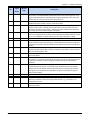
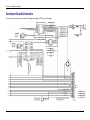
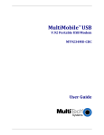
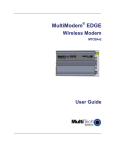
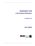
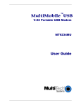
RJModem™ MT5656RJ Developer’s Guide Copyright and Technical Support RJModem™ Developer's Guide MT5656RJ PN S000363P Copyright This publication may not be reproduced, in whole or in part, without prior expressed written permission from Multi-Tech Systems, Inc. All rights reserved. Copyright © 2014 by Multi-Tech Systems, Inc. Multi-Tech Systems, Inc. makes no representations or warranties with respect to the contents hereof and specifically disclaim any implied warranties of merchantability or fitness for any particular purpose. Furthermore, Multi-Tech Systems, Inc. reserves the right to revise this publication and to make changes from time to time in the content hereof without obligation of Multi-Tech Systems, Inc. to notify any person or organization of such revisions or changes. Revisions Revision J Date 06/01/09 K 03/12/10 L M N O P 10/12/10 08/15/11 09/19/12 12/10/13 03/12/14 Description Updated Technical Support section on the copyright page. Added a link on the copyright to the MultiTech Web site for Multi-Tech Warranty information. Updated the EMC, Safety, and R&TTE Directive Compliance. Added RoHS statement, Chinese standards, and Brazilian bar code and approval. Added power consumption: sleep and idle modes. Added lead-free solderable (wave solder only) specifications. Changed the operating temperature range. Updated the –RESET text. Added the Technical Support section describing the use of the Multi-Tech Online Support Portal. Changed operating temperature and added UL note about temperature. Applied template. Updated references to product CD for developer’s kit. Updated RoHS statement. Added safety notice Russian notice Trademarks Trademarks and registered trademarks of Multi-Tech Systems, Inc. are RJModem and the Multi-Tech logo. Microsoft and Windows are registered trademarks or trademarks of Microsoft Corporation in the United States and/or other countries. Patents This device covered by one or more of the following patents: 6,031,867; 6,012,113; 6,009,082; 5,905,794; 5,864,560; 5,815,567; 5,815,503; 5,812,534; 5,809,068; 5,790,532; 5,764,628; 5,764,627; 5,754,589; 5,724,356; 5,673,268; 5,673,257; 5,644,594; 5,628,030; 5,619,508; 5,617,423; 5,600,649; 5,592,586; 5,577,041; 5,574,725; 5,559,793; 5,546,448; 5,546,395; 5,535,204; 5,500,859; 5,471,470; 5,463,616; 5,453,986; 5,452,289; 5,450,425; 5,355,365; 5,309,562; 5,301,274; 7,082,106; 7,082,141; 7,092,406. Other Patents Pending. Contacting Multi-Tech Support Multi-Tech Online Support Portal https://support.multitech.com To better serve our customers, manage support requests and shorten resolution times, we have created the online web portal allowing you to submit questions regarding Multi-Tech products directly to our technical support team. Get answers to your most complex questions, ranging from implementation, troubleshooting, product configuration, firmware upgrades and more. To create an account and submit a Support Case on the Portal, visit https://support.multitech.com Knowledge Base and Support Services: www.multitech.com/en_US/SUPPORT The Knowledge Base provides immediate answers to your questions and gives you access to support resolutions for all Multi-Tech products. Visit our support area on the website for other support services. Technical Support Country Europe, Middle East, Africa: U.S., Canada, all others: By Email [email protected] [email protected] By Phone +(44) 118 959 7774 (800) 972-2439 or (763) 717-5863 Warranty Warranty information can found at http://www.multitech.com/en_US/COMPANY/Policies/warranty/ World Headquarters Multi-Tech Systems, Inc. 2205 Woodale Drive Mounds View, Minnesota 55112 Phone: 763-785-3500 or 800-328-9717 Fax: 763-785-9874 Internet Address: http://www.multitech.com 2 Multi-Tech Systems, Inc. RJModem Developer's Guide Contents Chapter 1 – RJModem Hardware ....................................................................................................................5 RJModem Features ....................................................................................................................................................... 5 Product Ordering Information ...................................................................................................................................... 5 Ordering Codes .............................................................................................................................................................. 6 Developer Kit ................................................................................................................................................................ 6 AT Commands............................................................................................................................................................... 6 Technical Specifications ................................................................................................................................................ 7 Dimensions for Board Mounting and Panel Mounting .................................................................................................. 8 Board Mounting Dimensions ......................................................................................................................................... 8 Panel Mounting ............................................................................................................................................................. 9 Attaching the Mounting Bracket ................................................................................................................................... 9 Dimensional Drawing of the Bracket........................................................................................................................... 10 Cable Specifications .................................................................................................................................................... 10 PCB Footprint ............................................................................................................................................................. 11 Pin Out Dimensions .................................................................................................................................................... 12 PCB Footprint or Board Lay-out (Note: This is the PCB top view) ............................................................................... 12 Pin Descriptions .......................................................................................................................................................... 12 Top View ...................................................................................................................................................................... 12 Transmit Clock (TXCLK) and Receive Clock (RXCLK) ..................................................................................................... 14 Using &Q Command to Control the Connection Modes ............................................................................................. 14 Using &W Command to Save Configuration................................................................................................................ 15 Electrical Characteristics ............................................................................................................................................. 16 3.3 V Serial RJModem .................................................................................................................................................. 16 5 V Serial RJModem ..................................................................................................................................................... 16 Handling Precautions................................................................................................................................................... 16 Developer Board ......................................................................................................................................................... 17 5 V / 3.3 V Jumper – JP6 .............................................................................................................................................. 18 Block Diagram ............................................................................................................................................................. 19 Developer Board Schematics ...................................................................................................................................... 20 Design Considerations ................................................................................................................................................ 23 PC Board Layout Guidelines ........................................................................................................................................ 23 Electromagnetic Interference (EMI) Considerations ................................................................................................... 23 EMI Filtering ................................................................................................................................................................ 24 Chapter 2 – Safety and Regulatory Information............................................................................................. 25 Analog Telecom Safety Warnings ................................................................................................................................ 25 Telecom Approvals ..................................................................................................................................................... 26 EMC, Safety, and R&TTE Directive Compliance ........................................................................................................... 26 Industry Canada........................................................................................................................................................... 26 Brazil Approval............................................................................................................................................................. 27 Telecom Requirements for the United States ............................................................................................................. 27 47 CFR – FCC Part 15 ................................................................................................................................................... 27 47 CFR Part 68 Telecom ............................................................................................................................................... 27 New Zealand Telecom Warning Notice ....................................................................................................................... 29 Multi-Tech Systems, Inc. RJModem Developer's Guide 3 Contents Russian Statement ....................................................................................................................................................... 29 South African Statement ............................................................................................................................................. 30 Other ........................................................................................................................................................................... 30 International Modem Restrictions .............................................................................................................................. 30 Chapter 3 – Environment Statements ........................................................................................................... 31 Waste Electrical and Electronic Equipment (WEEE) Statement ................................................................................... 31 WEEE Directive ............................................................................................................................................................ 31 Instructions for Disposal of WEEE by Users in the European Union ........................................................................... 31 Restriction of the Use of Hazardous Substances (RoHS) .............................................................................................. 32 Information on HS/TS Substances According to Chinese Standards ............................................................................ 33 Information on HS/TS Substances According to Chinese Standards (in Chinese) ......................................................... 34 Index ........................................................................................................................................................... 35 4 Multi-Tech Systems, Inc. RJModem Developer's Guide Chapter 1 – RJModem Hardware The Multi-Tech RJModem creates communication-ready devices by integrating modem functions into the most compact, integrated device. The first-of-its-kind RJ11 form factor includes the controller, data pump, and DAA giving you the ability to integrate dial-up connectivity into any product design. With minimal engineering effort, the RJModem instantly adds global communication capabilities, enhancing the end user experience and increasing product value. RJModem Features ● Complete data modem including the controller, data pump, DAA, and RJ-11 connector ● V.92/56K, V.34/33.6K, V.32vis/14.4K data rate options ● High speed models backward compatible with lower speeds ● Telecom approved in more than 50 countries (some pending) ● V.44 and V.42 bis data compression ● V.42 error correction ● Intelligent DAA technology detects line status ● AT command compatible ● U. S. Caller ID reporting ● Low power/sleep mode ● FastPOS (V.29) and V.22vis Fast Connect ● V.80 Synchronous Access ● 3.3V or 5V power input options ● Board mount or remote panel mounting ● Two-year warranty Product Ordering Information Product Description Region Order this Product MT5656RJ-92 MT5656RJ-34 MT5656RJ-32 MT5656RJ-L-92 MT5656RJ-L-34 MT5656RJ-L-32 MTRJ-DK MTRJ-RMK V.92 Serial Data Only 5V V.34 Serial Data Only 5V V.32bis Serial Data Only 5V V.92bis Serial Data Only 3.3V V.34 Serial Data Only 3.3V V.32bis Serial Data Only 3.3V Developer Kit Panel Mounting Kit for RJModem Multi-Tech Systems, Inc. RJModem Developer's Guide Global Global Global Global Global Global Global Global 5 Chapter 1 – RJModem Hardware Ordering Codes Code 92 34 32 L Description V.92/56K Data Rate V.34/33.6K Data Rate V.32bis/14.4K Data Rate 3.3V Power Input Note: Lead-free builds of the RJModem are available. Developer Kit A Developer Kit is available. This kit provides the ability to plug in the RJModem and use it for testing, programming, and evaluation. The kit includes one developer board with RS-232 DB-25 connector, universal power supply, RS-232 cable, RJ-11 cable, and MTRJ-RMK Panel Mounting Kit, and Developer Kit CD, which contains a Developer Guide. AT Commands Use AT Commands to configure your RJModem. Refer to the RJModemand SocketModemIP AT Command Reference Guide, (part number S000364) available on the Multi-Tech Web site at www.multitech.com/setup/product.go. 6 Multi-Tech Systems, Inc. RJModem Developer's Guide Chapter 1 – RJModem Hardware Technical Specifications Category Data Standards Data Format Serial Speeds Client-to-Server Data Rates Client-to-Client Data Rates Error Correction Data Compression Modes of Operation Dimensions Weight Operating Temperature1 Storage Temperature Humidity Lead-Free Solder (Wave solder only) Temperature Operating Voltage Description V.92/V.90/56K, V.34/33.6K, V.32bis/14.4K, V.22, V.23, V.21; Bell 212A and Bell103 Serial, binary, asynchronous Serial port data rates adjustable to 300, 1200, 2400, 4800, 9600, 19,200, 38,400, 57,600, 115,200 Supports V.92 and V.90 data rates 33,600; 31,200; 28,800; 26,400; 24,000; 21,600; 19,200; 16,800; 14,400; 12,000; 9600; 7200; 4800; 2400; 1200; 0-300 bps Data Mode: V.42 (LAPM or MNP 2–4) V.44, V.42bis and MNP Class 5 Full duplex over dial-up lines; data mode, command mode, and online command mode, V.54 test mode .709" w x 2.519" h x .752 d (1.8 cm x 6.4 cm x 1.92 cm) 64 oz. (0.02 Kg) 3.3 V and 5V Build Options -40° to +85°C UL recognized @ 40° -40° to +85°C Humidity range 20% to 90% (non-condensing) RJModem can withstand lead-free wave solder temperatures up to 260° C (± 5°) for 6 seconds 5V DC Build Option ± 10% – Absolute Maximum Supply Voltage: 5.5VDC 3.3V DC Build Option ± 10% – Absolute Maximum Supply Voltage: 3.6VDC Power Consumption Sleep Input Voltage Current 23mA 97mA 3.3V Watts 315mW 340mW 5.0V Current 23mA Watts Transmit Level Receiver Sensitivity Frequency Stability DAA Isolation Flow Control Command Buffer Telephony / TAM Certifications and Approvals Warranty Typical Maximum 76mW 97mA 105mA 102mA 115mW 480mW 510mW -11 dBm (varies by country setting) -43 dBm under worst-case conditions ±0.01% 1.5Kv r.m.s. or 2121 VDC at working voltage of 250VAC XON/XOFF (software), RTS/CTS (hardware) 60 characters TAM (Telephone Answering Machine): S-101 AT+V commands (no CODEC for speakers/microphone interface) Safety Certifications EMC Approvals UL 60950-1 FCC Part 15 (Class B) IEC 60950-1 Canada (Class B) AS/NZS 6950:2000 EN 55022 (Class B) CCC EN 55024 Two years 1UL Listed at 40° C, limited by power supply. UL Certification does not apply or extend to an ambient above 40° C and has not been evaluated by UL for ambient greater than 40° C. “UL has evaluated this device for use in ordinary locations only. Installation in a vehicle or other outdoor locations has not been evaluated by UL. UL Certification does not apply or extend to use in vehicles or outdoor applications or in ambient above 40° C.” Répertorié UL à 40° C, limitée par la puissance d'alimentation. Multi-Tech Systems, Inc. RJModem Developer's Guide 7 Chapter 1 – RJModem Hardware Certification UL ne s'appliquent ni s'étendre à l'une température ambiante supérieure à 40° C et n'a pas été évalué par UL pour ambiante supérieure à 40° C. «UL a évalué cet appareil pour une utilisation dans des endroits ordinaires seulement. Installation dans un véhicule ou d'autres emplacements en plein air n'a pas été évaluée par UL. La certification UL ne s'applique pas ou s'étendre à utiliser dans des véhicules ou les applications en extérieur ou dans ambiante dépasse 40 ° C.» Dimensions for Board Mounting and Panel Mounting Board Mounting Dimensions Top View 8 Bottom View Multi-Tech Systems, Inc. RJModem Developer's Guide Chapter 1 – RJModem Hardware Panel Mounting Note: Screws, bracket and ribbon cable are included in the panel-mounting kit. Attaching the Mounting Bracket Multi-Tech Systems, Inc. RJModem Developer's Guide 9 Chapter 1 – RJModem Hardware Dimensional Drawing of the Bracket Cable Specifications 10 Multi-Tech Systems, Inc. RJModem Developer's Guide Chapter 1 – RJModem Hardware PCB Footprint Notes: Surface mount connectors are approved in place of soldering the unit to the motherboard. Follow the "Pass Through" footprint instructions on the part data sheets. The following are recommended by Multi-Tech: www.samtec.com SAMTEC: SMM-107-02-S-D-(other option) or equivalent SAMTEC: CLT-107-02-(plating option)-D-(other option) or equivalent Multi-Tech Systems, Inc. RJModem Developer's Guide 11 Chapter 1 – RJModem Hardware Pin Out Dimensions PCB Footprint or Board Lay-out (Note: This is the PCB top view) Pin Descriptions Top View PCB Top Surface Front RJModem Jack Opening 12 Multi-Tech Systems, Inc. RJModem Developer's Guide Chapter 1 – RJModem Hardware Pin Signal Name IN/OUT Type 1 –RI O 2 –DCD O 3 –DTR I 4 –RESET I 5 6 VCC –CTS PWR O 7 –RTS I 8 TXCLK O 9 –TXD I 10 –RXD O 11 12 13 CLK GND SPKR GND 14 RXCLK O Description RING (Active Low). Incoming ring signal from phone. Ring Indicate. –RI output ON (low) indicates the presence of an ON segment of a ring signal on the telephone line. The modem will not go off-hook when –RI is active; the modem waits for –RI to go inactive before going off-hook. Data Carrier Detect (Active Low). –DCD output is ON (low) when a data connection is established and the module is ready to send/receive data. Data Terminal Ready (Active Low). The –DTR input is turned ON (low) when the DTE is ready to communicate. –DTR ON prepares the modem to be connected, and, once connected, maintains the connection. –DTR OFF places the modem in the disconnect state under control of the &Dn and &Qn commands. Device Reset (with pull-up). The active low –RESET input resets the device logic and returns the configuration of the device to the original factory default values or "stored values" in the NVRAM. The pulse width for the reset signal should be >= 10mS. DC Input Power. 3.3 V or 5 V DC power, depending upon the build. Clear to Send (Active Low). –CTS is controlled by the module to indicate whether or not the module is ready to transmit data. –CTS ON indicates to the DTE that signals on TXD will be transmitted. –CTS OFF indicates to the DTE that it should not transfer data on TXD. Request to Sent (Active Low). –RTS signal is used for hardware flow control. –RTS input ON (low) indicates that the DTE is ready to send data to the modem. In the command state, the modem ignores –RTS. Transmit Data Sync Clock. TX synchronous data clock for sync data mode. More information below. Transmitted Data. The DTE uses the –TXD line to send data to the module for transmission or to transmit commands to the module. The DTE should hold this circuit in the mark state when no data is being transmitted or during intervals between characters. Received Data. The module uses the RXD line to send data to the DTE and to send module responses to the DTE. In command mode, –RXD data presents the module responses to the DTE. Module responses take priority over incoming data when the two signals are in competition for –RXD. When no data is transmitted, the signal is held in mark condition. Optional 28.224 or 27 mhz clk input (requires special build option) Logic Ground. Speaker. Call Progress signaling on MT5656RJ is a square wave output that can be optionally connected to a low-cost single-ended speaker; e.g., a sounducer or an analog speaker circuit. Receive Data Sync Clock. RX synchronous data clock for sync data mode. More information below. Multi-Tech Systems, Inc. RJModem Developer's Guide 13 Chapter 1 – RJModem Hardware Transmit Clock (TXCLK) and Receive Clock (RXCLK) Transmit Clock (TXCLK) and Receive Clock (RXCLK) pins are used in synchronous (sync) mode serial communication. They are needed when using a synchronous terminal device to keep synchronization between the modem and the terminal device on the serial port. Transmit Clock (TXCLK) and Receive Clock (RXCLK) are not used in asynchronous mode. However, most applications use asynchronous mode because synchronous ports are not as common as asynchronous ports on computer hardware. For asynchronous operation the host system does not need to connect to the TXCLK and the RXCLK pins on the RJModem; you can use a 9-pin interface. Use the &M command to set Synchronous mode. To save the current (active) configuration (profile), use the &W command. See the RJModem AT command guide available on the Multi-Tech Web site. Using &Q Command to Control the Connection Modes This command is an extension of the &M command. Use it to control the connection modes. It is used with S36 and S48. Note: If you issue &Q0 to &Q3 to select the mode, the subsequent connect message reports the DCE speed regardless of the W command and S95 settings. Syntax &Q<value> Defined Values <value> Decimal number corresponding to the selected option. 0 Selects direct asynchronous operation. The value 000b is written to S27 bits 3, 1, and 0, respectively. See &M0. 1 Selects synchronous connect mode with async off-line command mode. The value 001b is written to S27 bits 3, 1, and 0, respectively. See &M1. (Serial interface operation only.) 2 Selects synchronous connect mode with async off-line command mode and enables DTR dialing of directory 0. The value 010b is written to S27 bits 3, 1, and 0, respectively. See &M2. (Serial interface operation only.) 3 Selects synchronous connect mode with async off-line command mode and enables DTR to act as Talk/Data switch. The value 011b is written to S27 bits 3, 1, and 0, respectively. See &M3. (Serial interface operation only.) 5 The modem will try to negotiate an error-corrected link. The modem can be configured using S36 to determine whether a failure will result in the modem returning on-hook or will result in fallback to an asynchronous connection. The value 101b is written to S27 bits 3, 1, and 0, respectively. (Default.) 6 Selects asynchronous operation in normal mode (speed buffering). The value 110b is written to S27 bits 3, 1, and 0, respectively. Result Codes OK <value> = 0 to 3, 5, or 6 ERROR 14 Multi-Tech Systems, Inc. RJModem Developer's Guide Chapter 1 – RJModem Hardware Using &W Command to Save Configuration This command saves the current (active) configuration (profile), including S-Parameters, in one of the two user profiles in NVRAM as denoted by the parameter value. This command produces an ERROR message if the NVRAM is not installed or is not operating, as detected by the NVRAM test. The current configuration is comprised of a list of storable parameters as described in the &V command. These settings are restored to the active configuration upon receiving a Zn command or at power up (see &Yn). Syntax &W<value> Defined Values <value> Decimal number corresponding to the selected profile. 0 – Store the current configuration as profile 0. 1 – Store the current configuration as profile 1. Result Codes OK <value> = 0 or 1. ERROR Multi-Tech Systems, Inc. RJModem Developer's Guide 15 Chapter 1 – RJModem Hardware Electrical Characteristics 3.3 V Serial RJModem 3.3 V DC Characteristics (TA = 0°C to 70°C; VDD = 3.3 V ± 0.3 V) VDDMAX = 3.6 V Inputs –DTR (3), –TXD (9), –RTS (7), –RESET (3), XCLK (11), PWR (5), GND (12) Outputs –DCD (2), –CTS (6), –RI (1), –RXD (10), RDCLK (14), TDCLK (8) 2 mA, Z INT = 120 Digital Input Capacitance Input High Min 2.0 V Input Low Max 0.8 V Output High Min 2.4 V Output Low Max 0.5 V 20pF 5 V Serial RJModem 5 V DC Characteristics (TA = 0 °C to 50 °C; VDD = 5 V ± 0.25 V) VDDMAX = 5.5 V Inputs –DTR (3), –TXD (9), –RTS (7), –RESET (3), XCLK (11), PWR (5), GND (12) Outputs –DCD (2), –CTS (6), –RI (1), –RXD (10), RDCLK (14), TDCLK (8), SPKR (13) 2 mA, Z INT = 120 Digital Input Capacitance Input High Min 2 V Output High Min 2.4 V Input Low Max 0.8 V Output Low Max 0.5 V 20 PF Handling Precautions Handle all electronic devices with certain precautions to avoid damage due to the accumulation of static charge. Although input protection circuitry has been incorporated into the devices to minimize the effect of this static buildup, proper precautions should be taken to avoid exposure to electrostatic discharge during handling and mounting. 16 Multi-Tech Systems, Inc. RJModem Developer's Guide Chapter 1 – RJModem Hardware Developer Board Multi-Tech Systems, Inc. RJModem Developer's Guide 17 Chapter 1 – RJModem Hardware 5 V / 3.3 V Jumper – JP6 The operating voltage factory default setting is 3.3 V. The JP1 jumper must be set to 3.3-volt. Warning – Be sure that the 5 V/3.3 V jumper is set to match the requirements of your RJModem. If this jumper is set incorrectly, damage to the RJModem and/or the Test/Demo card can result. Caution – Use only the provided Multi-Tech Systems, Inc. transformer with the Test/Demo board. Use of any other power source voids the warranty and can damage the Test/Demo board and the RJModem. The transformer connector is keyed to prevent improper connection to the Test/Demo board. 18 Multi-Tech Systems, Inc. RJModem Developer's Guide Chapter 1 – RJModem Hardware Block Diagram Multi-Tech Systems, Inc. RJModem Developer's Guide 19 Chapter 1 – RJModem Hardware Developer Board Schematics To view the text and numbers, increase the viewing percentage to 150% or print the page. 20 Multi-Tech Systems, Inc. RJModem Developer's Guide Chapter 1 – RJModem Hardware To view the text and numbers, increase the viewing percentage to 150% or print the page. Multi-Tech Systems, Inc. RJModem Developer's Guide 21 Chapter 1 – RJModem Hardware To view the text and numbers, increase the viewing percentage to 150% or print the page. 22 Multi-Tech Systems, Inc. RJModem Developer's Guide Chapter 1 – RJModem Hardware Design Considerations Adhere to good engineering practices when designing a printed circuit board (PCB) containing the RJModem. Suppression of noise is essential to the proper operation and performance of the modem itself and for surrounding equipment. Consider two aspects of noise in an OEM board design containing the RJ Modem: on-board/off-board generated noise that can affect digital signal processing. Both on-board and off-board generated noise that is coupled onboard can affect interface signal levels and quality. Of particular concern is noise in frequency ranges affecting modem performance. On-board generated electromagnetic interference (EMI) noise that can be radiated or conducted off-board is a separate, but equally important, concern. This type of noise can affect the operation of surrounding equipment. Most local government agencies have stringent certification requirements that must be met for use in specific environments. Proper PC board layout (component placement, signal routing, trace thickness and geometry, and so on) component selection (composition, value, and tolerance), interface connections, and shielding are required for the board design to achieve desired modem performance and to attain EMI certification. The aspects of proper engineering practices are beyond the scope of this designer guide. The designer should consult noise suppression techniques described in technical publications and journals, electronics and electrical engineering text books, and component supplier application notes. PC Board Layout Guidelines In a 4-layer design, provide adequate ground plane covering the entire board. In 4-layer designs, power and ground are typically on the inner layers. All power and ground traces should be 0.05 inches wide. The recommended hole size for the RJ Modem pins is 0.036 in. +/-0.003 in. (check with CAD on this) in diameter. All creepages and clearances for the RJModem have been designed to meet requirements of safety standards EN60950. The requirements are based on a working voltage of 250V. Electromagnetic Interference (EMI) Considerations The following guidelines can help minimize EMI generation. Some of these guidelines are the same as, or similar to, the general guidelines but are mentioned again to reinforce their importance. To minimize the contribution of EMI by the RJModem to the design, the designer must understand the major sources of EMI and how to reduce them to acceptable levels. 1. Keep traces carrying high frequency signals as short as possible. 2. Provide a good ground plane or grid. In some cases, a multilayer board may be required with full layers for ground and power distribution. 3. Decouple power from ground with decoupling capacitors as close to the RJModem module power pins as possible. 4. Eliminate ground loops, which are unexpected current return paths to the power source and ground. 5. Decouple the power cord at the power cord interface with decoupling capacitors. Methods to decouple power lines are similar to decoupling telephone lines. 6. Locate high frequency circuits in a separate area to minimize capacitive coupling to other circuits. 7. Locate cables and connectors so as to avoid coupling from high frequency circuits. 8. Lay out the highest frequency signal traces next to the ground grid. 9. If a multilayer board design is used, make no cuts in the ground or power planes and be sure the ground plane covers all traces. Multi-Tech Systems, Inc. RJModem Developer's Guide 23 Chapter 1 – RJModem Hardware 10. Minimize the number of through-hole connections on traces carrying high frequency signals. 11. Avoid right angle turns on high frequency traces. Forty-five degree corners are good; however, radius turns are better. 12. On 2-layer boards with no ground grid, provide a shadow ground trace on the opposite side of the board to traces carrying high frequency signals. This will be effective as a high frequency ground return if it is three times the width of the signal traces. 13. Distribute high frequency signals continuously on a single trace rather than several traces radiating from one point. EMI Filtering The RJModem includes EMI filtering as illustrated in the following schematic: 24 Multi-Tech Systems, Inc. RJModem Developer's Guide Chapter 2 – Safety and Regulatory Information Analog Telecom Safety Warnings Before servicing, disconnect this product from its power source and telephone network. Also: ● Never install telephone wiring during a lightning storm. ● Never install a telephone jack in wet locations unless the jack is specifically designed for wet locations. ● Use this product with UL and cUL listed computers only. ● Never touch uninsulated telephone wires or terminals unless the telephone line has been disconnected at the network interface. ● Use caution when installing or modifying telephone lines. ● Avoid using a telephone during an electrical storm. There may be a remote risk of electrical shock from lightning. ● Do not use a telephone in the vicinity of a gas leak. CAUTION: To reduce the risk of fire, use only 26 AWG or larger UL Listed or CSA Certified telecommunication Line cord. Avertissements de sécurité télécom analogique Avant de l'entretien, débrancher ce produit de son réseau d'alimentation et de téléphone. également: ● Ne jamais installer du câblage téléphonique pendant un orage électrique. ● Ne jamais installer de prises téléphoniques à des endroits mouillés à moins que la prise ne soit conçue pour de tels emplacements. ● Utilisez ce produit avec UL et cUL ordinateurs répertoriés seulement. ● Ne jamais toucher fils ou des bornes téléphoniques non isolés à moins que la ligne téléphonique n'ait été déconnectée au niveau de l'interface réseau. ● Faire preuve de prudence au moment d'installer ou de modifier des lignes téléphoniques. ● Éviter d'utiliser le téléphone pendant un orage électrique. Il peut y avoir un risque de choc électrique causé par la foudre. ● N'utilisez pas un téléphone à proximité d'une fuite de gaz. ATTENTION: Pour réduire les risques d’incendie, utiliser uniquement des conducteurs de telecommunications 26 AWG au de section supérleure. Multi-Tech Systems, Inc. RJModem Developer's Guide 25 Chapter 2 – Telecom Approvals and Regulatory Information Telecom Approvals Multi-Tech's analog dial-up global RJModem is designed and approved for connection to the public switched telephone network in more than 50 countries or regions worldwide. Multi-Tech's RJModem is approved as host independent, which means our certification efforts can be transferred directly to your end product. Contact Multi-Tech at [email protected] to obtain a current list of approvals for the RJModem. EMC, Safety, and R&TTE Directive Compliance The CE mark is affixed to this product to confirm compliance with the following European Community Directives: Council Directive 2004/108/EC of 15 December 2004 on the approximation of the laws of Member States relating to electromagnetic compatibility; and Council Directive 2006/95/EC of 12 December 2006 on the harmonization of the laws of Member States relating to electrical equipment designed for use within certain voltage limits; and Council Directive 1999/5/EC of 9 March 1999 on radio equipment and telecommunications terminal equipment and the mutual recognition of their conformity. Industry Canada This Class B digital apparatus meets all requirements of the Canadian Interference-Causing Equipment Regulations. Cet appareil numérique de la classe B respecte toutes les exigences du Reglement Canadien sur le matériel brouilleur. This device complies with Industry Canada RSS Appliance radio exempt from licensing. The operation is permitted for the following two conditions: the device may not cause harmful interference, and 2. the user of the device must accept any interference suffered, even if the interference is likely to jeopardize the operation. Le présent appareil est conforme aux CNR d'Industrie Canada applicables aux appareils radio exempts de licence. L'exploitation est autorisée aux deux conditions suivantes: 1. l'appareil ne doit pas produire de brouillage, et 2. l'utilisateur de l'appareil doit accepter tout brouillage radioélectrique subi, même si le brouillage est susceptible d'en compromettre le fonctionnement. 1. 26 Multi-Tech Systems, Inc. RJModem Developer's Guide Chapter 2 – Telecom Approvals and Regulatory Information Brazil Approval This product has been homologated by ANATEL. This product meets the applied technical requirements in accordance with the procedures regulated by ANATEL. Reference of homologation of this product can be viewed in ANATEL web page: http://www.anatel.gov.br Telecom Requirements for the United States 47 CFR – FCC Part 15 This equipment has been tested and found to comply with the limits for a Class B digital device, pursuant to part 15 of the FCC Rules. These limits are designed to provide reasonable protection against harmful interference in a residential installation. This equipment generates, uses, and can radiate radio frequency energy and, if not installed and used in accordance with the instructions, may cause harmful interference to radio communications. However, there is no guarantee that interference will not occur in a particular installation. If this equipment does cause harmful interference to radio or television reception, which can be determined by turning the equipment off and on, the user is encouraged to try to correct the interference by one or more of the following measures: ● Reorient or relocate the receiving antenna. ● Increase the separation between the equipment and receiver. ● Connect the equipment into an outlet on a circuit different from that to which the receiver is connected. ● Consult the dealer or an experienced radio/TV technician for help. ● Warning: Changes or modifications to this unit not expressly approved by the party responsible for compliance could void the user’s authority to operate the equipment. Warning: Changes or modifications to this unit not expressly approved by the party responsible for compliance could void the user’s authority to operate the equipment. 47 CFR Part 68 Telecom 1. This equipment complies with Part 68 of the 47 CFR rules and the requirements adopted by the ACTA. Located on this equipment is a label that contains, among other information, the registration number and Ringer Equivalence Number (REN) for this equipment or a product identifier in the format: For current products: US:AAAEQ##Txxxx. For legacy products: AU7USA-xxxxx-xx-x If requested, this number must be provided to the telephone company. 2. A plug and jack used to connect this equipment to the premises wiring and telephone network must comply with the applicable 47 CFR Part 68 rules and requirements adopted by the ACTA. It’s designed to be connected to a compatible modular jack that is also compliant. Multi-Tech Systems, Inc. RJModem Developer's Guide 27 Chapter 2 – Telecom Approvals and Regulatory Information 3. The Ringer Equivalence Number (REN) is used to determine the number of devices that may be connected to a telephone line. Excessive RENs on a telephone line may result in the devices not ringing in response to an incoming call. In most but not all areas, the sum of RENs should not exceed five (5.0). To be certain of the number of devices that may be connected to a line, as determined by the total RENs, contact the local telephone company. For products approved after July 23, 2001, the REN for this product is part of the product identifier that has the format US:AAAEQ##Txxxx. The digits represented by ## are the REN without a decimal point (e.g., 03 is a REN of 0.3). For earlier products, the REN is separately shown on the label. 4. If this equipment causes harm to the telephone network, the telephone company will notify you in advance that temporary discontinuance of service may be required. But if advance notice isn't practical, the telephone company will notify the customer as soon as possible. Also, you will be advised of your right to file a complaint with the FCC if you believe it is necessary. 5. The telephone company may make changes in its facilities, equipment, operations or procedures that could affect the operation of the equipment. If this happens, the telephone company will provide advance notice in order for you to make necessary modifications to maintain uninterrupted service. 6. If trouble is experienced with this equipment, please contact Multi-Tech Systems, Inc. at the address shown below for details of how to have the repairs made. If the equipment is causing harm to the telephone network, the telephone company may request that you disconnect the equipment until the problem is resolved. 7. Connection to party line service is subject to state tariffs. Contact the state public utility commission, public service commission or corporation commission for information. 8. No repairs are to be made by you. Repairs are to be made only by Multi-Tech Systems or its licensees. Unauthorized repairs void registration and warranty. 9. If your home has specially wired alarm equipment connected to the telephone line, ensure the installation of this equipment does not disable your alarm equipment. If you have questions about what will disable alarm equipment, consult your telephone company or a qualified installer. 10. Connection to party line service is subject to state tariffs. Contact the state public utility commission, public service commission or corporation commission for information. 11. This equipment is hearing aid compatible. 12. Manufacturing Information on telecommunications device (modem): 28 Manufacturer: Multi-Tech Systems, Inc. Trade Name: RJModem Model Number: MT5656RJMI Registration No: AU7MM01BMT5656RJ Ringer Equivalence: 0.1B Modular Jack (USOC): RJ11C or RJ11W (single line) Service Center in USA: Multi-Tech Systems, Inc. 2205 Woodale Drive Mounds View, MN 55112 U.S.A. (763) 785-3500 (763) 785-9874 Fax Multi-Tech Systems, Inc. RJModem Developer's Guide Chapter 2 – Telecom Approvals and Regulatory Information New Zealand Telecom Warning Notice 1. The grant of a Telepermit for any item of terminal equipment indicates only that Telecom has accepted that the item complies with minimum conditions for connection to its network. It indicates no endorsement of the product by Telecom, nor does it provide any sort of warranty. Above all, it provides no assurance that any item will work correctly in all respects with another item of Telepermitted equipment of a different make or model, nor does it imply that any product is compatible with all of Telecom’s network services. This equipment is not capable under all operating conditions of correct operating conditions of correct operation at the higher speed which it is designated. 33.6 kbps and 56 kbps connections are likely to be restricted to lower bit rates when connected to some PSTN implementations. Telecom will accept no responsibility should difficulties arise in such circumstances. 2. Immediately disconnect this equipment should it become physically damaged, and arrange for its disposal or repair. This modem shall not be used in any manner which could constitute a nuisance to other Telecom customers. 4. This device is equipped with pulse dialing, while the Telecom standard is DTMF tone dialing. There is no guarantee that Telecom lines will always continue to support pulse dialing. 3. Use of pulse dialing, when this equipment is connected to the same line as other equipment, may give rise to 'bell tinkle' or noise and may also cause a false answer condition. Should such problems occur, the user should NOT contact the Telecom Faults Service. The preferred method of dialing is to use DTMF tones, as this is faster than pulse (decadic) dialing and is readily available on almost all New Zealand telephone exchanges. 5. Warning Notice: No '111' or other calls can be made from this device during a mains power failure. 6. This equipment may not provide for the effective hand-over of a call to another device connected to the same line. 7. Some parameters required for compliance with Telecom’s Telepermit requirements are dependent on the equipment (PC) associated with this device. The associated equipment shall be set to operate within the following limits for compliance with Telecom’s Specifications: For repeat calls to the same number: There shall be no more than 10 call attempts to the same number within any 30 minute period for any single manual call initiation, and ● The equipment shall go on-hook for a period of not less than 30 seconds between the end of one attempt and the beginning of the next attempt. For automatic calls to different numbers: ● The equipment shall be set to ensure that automatic calls to different numbers are spaced such that there is no less than 5 seconds between the end of one call attempt and the beginning of another. 8. For correct operation, total of the RN’s of all devices connected to a single line at any time should not exceed 5. ● Russian Statement MT5656RJ is Russia approved, Declaration of Conformity # Д-ТФ-0708 valid till 20.02.2017 (for MT5656RJ). Multi-Tech Systems, Inc. RJModem Developer's Guide 29 Chapter 2 – Telecom Approvals and Regulatory Information South African Statement This modem must be used in conjunction with an approved surge protection device. Other The above country-specific examples do not cover all countries with specific regulations; they are included to show you how each country may differ. If you have trouble determining your own country's requirements, check with Multi-Tech's Technical Support for assistance. International Modem Restrictions Some dialing and answering defaults and restrictions may vary for international modems. Changing settings may cause a modem to become non-compliant with national telecom requirements in specific countries. Also note that some software packages may have features or lack restrictions that may cause the modem to become noncompliant. 30 Multi-Tech Systems, Inc. RJModem Developer's Guide Chapter 3 – Waste Electrical and Electronic Equipment (WEEE) Statement, RoHS, Chinese Standards Chapter 3 – Environment Statements Waste Electrical and Electronic Equipment (WEEE) Statement WEEE Directive The WEEE Directive places an obligation on EU-based manufacturers, distributors, retailers, and importers to take-back electronics products at the end of their useful life. A sister directive, ROHS (Restriction of Hazardous Substances) complements the WEEE Directive by banning the presence of specific hazardous substances in the products at the design phase. The WEEE Directive covers all Multi-Tech products imported into the EU as of August 13, 2005. EU-based manufacturers, distributors, retailers and importers are obliged to finance the costs of recovery from municipal collection points, reuse, and recycling of specified percentages per the WEEE requirements. Instructions for Disposal of WEEE by Users in the European Union The symbol shown below is on the product or on its packaging, which indicates that this product must not be disposed of with other waste. Instead, it is the user’s responsibility to dispose of their waste equipment by handing it over to a designated collection point for the recycling of waste electrical and electronic equipment. The separate collection and recycling of your waste equipment at the time of disposal will help to conserve natural resources and ensure that it is recycled in a manner that protects human health and the environment. For more information about where you can drop off your waste equipment for recycling, please contact your local city office, your household waste disposal service or where you purchased the product. July, 2005 Multi-Tech Systems, Inc. RJModem Developer's Guide 31 Chapter 3 – Waste Electrical and Electronic Equipment (WEEE) Statement, RoHS, Chinese Standards Restriction of the Use of Hazardous Substances (RoHS) Multi-Tech Systems, Inc. Certificate of Compliance 2011/65/EU Multi-Tech Systems confirms that its embedded products comply with the chemical concentration limitations set forth in the directive 2011/65/EU of the European Parliament (Restriction of the use of certain Hazardous Substances in electrical and electronic equipment - RoHS) These Multi-Tech products do not contain the following banned chemicals1: ● Lead, [Pb] < 1000 PPM ● Mercury, [Hg] < 1000 PPM ● Hexavalent Chromium, [Cr+6] < 1000 PPM ● Cadmium, [Cd] < 100 PPM ● Polybrominated Biphenyl, [PBB] < 1000 PPM ● Polybrominated Diphenyl Ether, [PBDE] < 1000 PPM Environmental considerations: ● Moisture Sensitivity Level (MSL) =1 ● Maximum Soldering temperature = 260C (in SMT reflow oven) 1Lead usage in some components is exempted by the following RoHS annex, therefore higher lead concentration would be found in some modules (>1000 PPM); –Resistors containing lead in a glass or ceramic matrix compound. 32 Multi-Tech Systems, Inc. RJModem Developer's Guide Chapter 3 – Waste Electrical and Electronic Equipment, RoHS, Chinese Standards Information on HS/TS Substances According to Chinese Standards In accordance with China’s Administrative Measures on the Control of Pollution Caused by Electronic Information Products (EIP) # 39, also known as China RoHS, the following information is provided regarding the names and concentration levels of Toxic Substances (TS) or Hazardous Substances (HS) which may be contained in Multi-Tech Systems Inc. products relative to the EIP standards set by China’s Ministry of Information Industry (MII). Hazardous/Toxic Substance/Elements Name of the Component Lead (PB) Mercury (Hg) Cadmium (CD) Hexavalent Chromium (CR6+) Polybrominated Polybrominated Biphenyl (PBB) Diphenyl Ether (PBDE) Printed Circuit Boards O O O O O O Resistors X O O O O O Capacitors X O O O O O Ferrite Beads O O O O O O Relays/Opticals O O O O+ O O ICs O O O O O O Diodes/ Transistors O O O O O O Oscillators and Crystals X O O O O O Regulator O O O O O O Voltage Sensor O O O O O O Transformer O O O O O O Speaker O O O O O O Connectors O O O O O O LEDs O O O O O O Screws, Nuts, and other Hardware X O O O O O AC-DC Power Supplies O O O O O O Software / Documentation CDs O O O O O O Booklets and Paperwork O O O O O O Chassis O O O O O O X Represents that the concentration of such hazardous/toxic substance in all the units of homogeneous material of such component is higher than the SJ/Txxx-2006 Requirements for Concentration Limits. O Represents that no such substances are used or that the concentration is within the aforementioned limits. Multi-Tech Systems, Inc. RJModem Developer's Guide 33 Chapter 3 – Waste Electrical and Electronic Equipment (WEEE) Statement, RoHS, Chinese Standards Information on HS/TS Substances According to Chinese Standards (in Chinese) 依照中国标准的有毒有害物质信息 根据中华人民共和国信息产业部 (MII) 制定的电子信息产品 (EIP) 标准-中华人民共和国《电子信息产品污染控制管理办法》(第 39 号),也称作中国 RoHS,下表列出了 Multi-Tech Systems, Inc. 产品中可能含有的有毒物质 (TS) 或有害物质 (HS) 的名称及含量水平方面的信息。 有害/有毒物质/元素 成分名称 铅 (PB) 汞 (Hg) 镉 (CD) 六价铬 (CR6+) 多溴联苯 (PBB) 多溴二苯醚 (PBDE) 印刷电路板 O O O O O O 电阻器 X O O O O O 电容器 X O O O O O 铁氧体磁环 O O O O O O 继电器/光学部件 O O O O O O IC O O O O O O 二极管/晶体管 O O O O O O 振荡器和晶振 X O O O O O 调节器 O O O O O O 电压传感器 O O O O O O O O O O O O 变压器 O O O O O O 扬声器 O O O O O O 连接器 LED O O O O O O X O O O O O 螺丝、螺母以及其 它五金件 O O O O O O 交流-直流电源 O O O O O O 软件/文档 CD O O O O O O 手册和纸页 O O O O O O 底盘 X 表示所有使用类似材料的设备中有害/有毒物质的含量水平高于 SJ/Txxx-2006 限量要求。 O 表示不含该物质或者该物质的含量水平在上述限量要求之内。 34 Multi-Tech Systems, Inc. RJModem Developer's Guide Index & M &Q – Sync/Async Mode ..................................................14 &W – Store Current Configuration .................................15 Mounting Bracket Attachment ......................................... 9 5 5 V/3.3 V Jumper ............................................................18 A Asynchronous mode .......................................................14 B Block Diagram .................................................................19 C China’s Administrative Measures on the Control of Pollution ................................................................ 33, 34 D Data Rates .........................................................................7 Design Considerations ....................................................23 Developer Board .............................................................17 Developer Kit ....................................................................6 Dimensions for Board Mounting ......................................8 E Electrical Characteristics .................................................16 Electromagnetic Interference Considerations ................23 EMC Approvals ..................................................................7 EMC requirements Industry Canada ..........................................................26 EMC, Safety, and R&TTE Directive Compliance ..............26 EMI filtering schematic ...................................................24 H N New Zealand Telecom Warning Notice .......................... 29 O Operating Voltage............................................................. 7 Operational Temperature ................................................. 7 Ordering Information ....................................................... 6 P Panel Mounting ................................................................ 9 PCB Footprint .................................................................. 11 Pinouts ............................................................................ 13 Power Consumption ......................................................... 7 R Receive Clock (RXCLK) ..................................................... 14 RoHS Compliance............................................................ 32 S Safety Certifications .......................................................... 7 Schematics .......................................................... 20, 21, 22 Synchronous mode ......................................................... 14 T Telecom Approvals ......................................................... 26 Transmit Clock (TXCLK) ................................................... 14 V Voice Telephone Answering Machine .................................... 7 Handling Precautions ......................................................16 W I Wave Solder Temperatures .............................................. 7 WEEE Directive ............................................................... 31 International Modem Restrictions ..................................30 35 Multi-Tech Systems, Inc. RJModem Developer's Guide