1
PUMPED BLEND
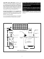
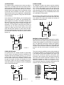
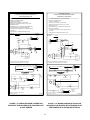
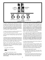
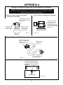
An additional circulator can also be used to provide a
return water temperature blend. This method works well
with systems with multiple zones with circulators (see
Fig. 1.7). The dedicated bypass circulator provides a
strong blending flow without diminishing the flow available to any heating zone. Any residentially sized circulator is adequate for this purpose.
SYSTEM BYPASS
For systems using a circulator on the return as either a
single zone, or multiple zones with zone valves, install a
system bypass line between the supply and return on
the suction side of the circulator (see Fig 1.5). Install a
metering valve in this bypass line to regulate the amount
of flow that will be diverted to the return. A plug valve
offers the best control for this application. Although other
valves may be less expensive, a plug valve will be easier
to set accurately.
Each of these bypass solutions also has the added benefit of increasing circulation in the boiler which will maximize tankless coil output and increase the accuracy of
temperature sensing controls.
In the absence of a flow indicator, set the metering valve
using temperature as a guide. The accompanying diagram suggests one scenario. This addition requires only
two tees, a plug valve, and a small amount of pipe and
offers the simplest approach to reliably controling condensation. For this system and those that follow, be
aware that you are using a percentage of the pump
capacity to blend, but the friction loss for the entire
pump flow has been reduced. In most cases, the standard pump packaged with the boiler has enough capacity to feed the baseboard distribution system and the
bypass line.
SUPPLY
RETURN
100%
120° F
100%
160° F
100%
160° F
200%
140° F
200%
160° F
PUMPED
BYPASS
SUPPLY
REVERSE ACTING AQUASTATS
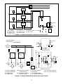
An alternative for existing systems experiencing condensation that does not require re-piping the boiler utilizes a
reverse acting aquastat, one that makes on temperature
rise. This approach works best in single zone systems.
Wired in series with the circulator, this control holds the
circulator off until the boiler reaches an acceptable temperature and then starts system circulation (see Fig.
1.8).
50%
120° F
50%
160° F
50%
160° F
100%
160° F
FIGURE 1.7
RETURN
100%
140° F
SYSTEM
BYPASS
FIGURE 1.5
The most commonly available reverse acting aquastat is
a Honeywell L4006B. The aquastat should be mounted
in an immersion well directly installed in the boiler. The
use of heat conductive grease (Honeywell par t
# 972545) in the immersion well is strongly recommended for fast and accurate temperature response. Set this
adjustable aquastat to make at no less than 130° F.
While this method can cause the circulator to cycle
more frequently, setting the aquastat’s differential to the
maximum (25-30°F) will minimize short cycling.
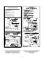
PUMP AWAY BYPASS
For systems that use a single circulator to pump away
from the boiler, the bypass should be installed on the
discharge side of the circulator (see Fig. 1.6). Full temperature water supplies the baseboard distribution system as before. Half of the circulator’s volume moves
through the bypass, blending and heating the cooler
return water. Again, the cost of installing the bypass is
small and setting it by temperature can be accomplished
with a contact thermometer.
115 volts
SUPPLY
reverse
aquastat
RETURN
N.O.
50%
120° F
50%
160° F
circulator
50%
160° F
100%
160° F
100%
140° F
24 volts
T
t'stat
T
PUMP AWAY
BYPASS
FIGURE 1.6
REVERSE
AQUASTAT
operating
aquastat
SET AT 120° F
N.C.
GV
FIGURE 1.8
6