1
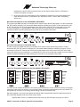
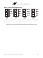
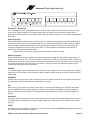
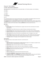
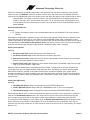
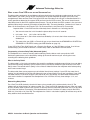
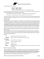
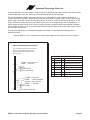
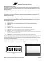
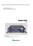
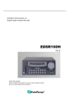
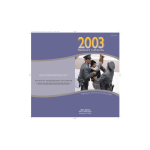
Advanced Technology Video, Inc.
English .......................................................... p. 2
Español ........................................................ p. 29
Français ........................................................ p. 57
Deutsch ........................................................ p. 85
Advanced Technology Video, Inc.
INTRODUCTION
Thank you for purchasing Advanced Technology Video’s MX/SX multiplexer. This instruction manual describes
the powerful features of this product for basic and advanced operation. It also covers the installation steps that
will allow quick and easy integration into your security system.
The following section provides an overview of the operational features of your ATV Multiplexer. If you are familiar
with the multiplexer, you should proceed to the Installation section on page 7 for step-by-step installation
instructions.
IMPORTANT INFORMATION
Before proceeding, please read and observe all instructions and warnings contained in this manual. Retain this
manual with the original bill of sale for future reference and, if necessary, warranty service.
Complete the following product purchase information. The factory requests this information when contacted for
technical support.
Purchase Date:
________________________________
Serial Number:
________________________________
MX/SX: Instructions for Basic Operation and Installation
Page 2
Advanced Technology Video, Inc.
Table of Contents
Introduction ...................................................................................................................................................................................2
Important Information ...................................................................................................................................................................2
Chapter 1 - Features ....................................................................................................................................................................5
Definition of Duplex & Simplex Multiplexers ..........................................................................................................................5
Live Camera Displays (Duplex models) ................................................................................................................................5
Live Camera Displays (Simplex models)...............................................................................................................................5
Multiplexer Recording/Playback.............................................................................................................................................5
DigiLock™ and Playback.......................................................................................................................................................5
VCR Bypass ..........................................................................................................................................................................5
Advanced Alarm System with Alarm Scheduling ..................................................................................................................6
Alarm Log and Printing..........................................................................................................................................................6
Installation .............................................................................................................................................................................7
Chapter 2 - Installation .................................................................................................................................................................7
Back Panel Connections for the QSP-860MPX, QSP-860SPX ............................................................................................8
Back Panel Connections for the MX4M, SX4M.....................................................................................................................8
Video Line Termination Switches for the QSP-860MPX, QSP-860SPX ...............................................................................8
Video Line Termination Switches for the MX4m, SX4m........................................................................................................9
Chapter 3 - Operation.................................................................................................................................................................10
DISPLAY (Duplex) ...............................................................................................................................................................10
DISPLAY (Simplex)..............................................................................................................................................................10
FREEZE ..............................................................................................................................................................................10
SEQUENCE ........................................................................................................................................................................10
PIP.......................................................................................................................................................................................10
QUADRANT.........................................................................................................................................................................10
ZOOM ..................................................................................................................................................................................10
VCR .....................................................................................................................................................................................11
VCR Bypass Function .........................................................................................................................................................11
CAMERA Buttons ................................................................................................................................................................11
Remote Control Operation ..................................................................................................................................................11
Chapter 4 - Set Up Menus..........................................................................................................................................................12
For MX4m, SX4m MULTIPLEXERS ONLY:.........................................................................................................................12
Main Menu...........................................................................................................................................................................12
Set Time/Date ...............................................................................................................................................................12
Other Display Options ............................................................................................................................................13
VCR Set Up ..................................................................................................................................................................13
VCR Selection ........................................................................................................................................................13
Camera Set Up .............................................................................................................................................................14
Camera Label Changing ........................................................................................................................................14
CUSTOMPLEXING™ (Camera Multiplexing Priority) ............................................................................................14
Camera Monitor Disable.........................................................................................................................................14
Display Sequencing Format ...................................................................................................................................15
Sequencing Format Screens..................................................................................................................................15
Alarm Set Up ................................................................................................................................................................16
External Alarms......................................................................................................................................................16
Video Loss Alarms .................................................................................................................................................16
Alarm Scheduling .........................................................................................................................................................16
Set Alarm Enable Schedule ...................................................................................................................................16
Enable Scheduled Alarms......................................................................................................................................17
Alarm Control Options............................................................................................................................................17
Alarm Dwell Adjustment .........................................................................................................................................17
Alarm Activation Type .............................................................................................................................................18
Alarm Log ...............................................................................................................................................................18
Other Options ...............................................................................................................................................................18
Security Set Up ......................................................................................................................................................19
Advanced VCR Options..........................................................................................................................................19
Camera Switch Input ..............................................................................................................................................19
Hand Held IR Remote Control....................................................................................................................................................20
Programming your ATV multiplexer Remote Control...........................................................................................................20
MX/SX: Instructions for Basic Operation and Installation
Page 3
Advanced Technology Video, Inc.
What to do if Your VCR is not on the Supported List .................................................................................................................21
Programming a Custom Delay Table (Advanced Option)....................................................................................................21
What is the Delay Table?.....................................................................................................................................................21
Determining Delay Values ...................................................................................................................................................21
Edit Delay Table...................................................................................................................................................................22
How do I verify the correct Values?.....................................................................................................................................22
Alarm Interconnection on the multiplexer ...................................................................................................................................22
RS-232 Remote Control Interface .......................................................................................................................................25
Supported VCRs..................................................................................................................................................................26
Equipment Requirements ...........................................................................................................................................................27
Specifications..............................................................................................................................................................................27
Warranty Information ..................................................................................................................................................................28
YEAR 2000 CONFORMANCE ............................................................................................................................................28
LIMITATION OF WARRANTY..............................................................................................................................................28
FCC Statement....................................................................................................................................................................28
MX/SX: Instructions for Basic Operation and Installation
Page 4
Advanced Technology Video, Inc.
CHAPTER 1 - FEATURES
Definition of Duplex & Simplex Multiplexers
Duplex Multiplexers (QSP-860MPX, MX4m) Simplex Multiplexers (QSP-860SPX, SX4m)
Duplex versions of the multiplexers (include QSP-860MPX, MX4m) allow you to watch all cameras in multicamera displays as well as one camera at a time in both LIVE mode and VCR Playback.
Simplex versions of the multiplexers (include QSP-860SPX, SX4m) only allow you to watch one camera at a
time (either by itself or sequencing) in LIVE mode. It is still recording all the cameras all the time. On playback,
you can watch multi-camera displays such as Split Screen, Picture-In-Picture and more, but only on VCR
playback. This is very useful where there are multiple locations with multiplexers, or where there is no on-site
monitoring.
Live Camera Displays (Duplex models)
The MX is initially in the Live Camera Display mode whenever power is applied to the unit. Live cameras can be
displayed in 3x3, quad, PIP, dual PIP, split screen, squish screen, or full frame formats. In addition, any display
can be frozen using a front panel button, the IR remote control, or external signal input. In any of these display
modes, the unit can be programmed to sequence one or more cameras with a programmable dwell time.
Live Camera Displays (Simplex models)
The SX is initially in the Live Camera Display mode whenever power is applied to the unit. Live cameras can be
displayed in full frame format. In these display modes, the unit can be programmed to sequence one or more
cameras with a programmable dwell time.
Multiplexer Recording/Playback
The multiplexer records each camera individually onto a single video frame of the VCR tape at a rate compatible
with the VCR recording speed (record hours mode). Proper VCR playback operation requires that the multiplexer
be set up to multiplex at the rate compatible with your VCR recording speed (see VCR Set Up page 13). During
multiplexing, a single frame from each camera is alternately output to the VCR with the factory default set so that
each live camera is given an equal number of frames on the tape. Dead or unconnected camera inputs will not
be recorded. In order to optimize recording for your security situation, the frequency with which individual camera
inputs are sampled for multiplexing may be optionally configured using the Customplexing™ camera multiplexing
priority function. The camera multiplexing priority set up menu allows you to set four levels of priority (giving
more frames to high priority and less frames to low priority). While multiplex recording is active, the live display
mode can be set to any mode without affecting the multiplex recording function.
In VCR playback mode, cameras can be displayed in 3x3, quad, PIP, dual PIP, split screen, squish screen, or full
frame formats. Any display can be frozen. VCR playback incorporates digital decoding of the camera number
from the tape so that monitor screen images may be updated at the rate that images appear on the tape. The
default refresh rate of the playback monitor is the playback rate divided by the number of cameras being
multiplexed. This will change when alarmed cameras or dead cameras are present or camera priorities have
been changed.
DigiLock™ and Playback
In VCR playback mode, digital information is used to compensate for the poor vertical synchronization signals
frequently encountered with time lapse VCRs.
The multiplexer DigiLock™ decoding reconstructs the timing so that successfully decoded frames are read into
monitor display memory consistently without any jumping, tearing, or other side-effects of poor synchronization.
VCR Bypass
Many VCRs have on-screen programming menus that require a monitor for programming the VCR. The
MX/SX: Instructions for Basic Operation and Installation
Page 5
Advanced Technology Video, Inc.
multiplexer includes a VCR Bypass feature that facilitates VCR programming by allowing the multiplexer’s VCR
input (VCR’s video output) to be routed directly to the display monitor. The VCR Bypass mode can also be used
to directly view the VCR’s output for adjusting tracking or verifying proper VCR connections to the multiplexer.
Advanced Alarm System with Alarm Scheduling
Your multiplexer contains the most advanced and flexible Alarm System available. The advanced Alarm System
supports External Alarms and Video Loss Alarms. In addition, alarm system can be enabled and disabled
through a 7-day Alarm Schedule and/or a user programmable external Master Enable signal.
Your multiplexer has alarm channels associated with the number of camera inputs. Each alarm channel includes
a programmable External Alarm and Video Loss Alarm. External alarm inputs are individually selectable for
contact closure or opening as well as logic levels (+5V, 0V). Each alarm channel may also be individually
selected for enable/disable through the multiplexer Alarm Schedule. The Alarm Schedule is a 7-day timer
schedule with a single ON and OFF time associated with each day of the week. The multiplexer also has an
external input signal that can be selected between picture Freeze and Alarm Master Enable. The Alarm Master
Enable signal can be used in conjunction with your burglar alarm control panel so that the alarm control panel
can enable or disable the multiplexers alarm system. For more information on "Alarm Scheduling" see page 16.
Alarm Log and Printing
Your multiplexer has an internal Alarm Log that provides storage for up to 100 alarm events. In addition, its text
can be transmitted to the serial port for printing or storage on a host computer. The Alarm Log is a circular
storage buffer so that the most recent alarm events are always stored. Alarm event text can also be sent directly
to the serial port, when an event occurs, for immediate printing or external processing. Alarm events, which may
be printed and stored in the Alarm Log, include any enabled External Alarms or Video Loss Alarms. For
instructions on the use of the multiplexers alarm log and printing features see Alarm Log on page 18.
MX/SX: Instructions for Basic Operation and Installation
Page 6
Advanced Technology Video, Inc.
Installation
The above diagram shows the typical 8-camera installation for your multiplexer. Up to eight cameras can be
connected to the multiplexer using the back panel connectors.
Important Note: The VCR and monitor connections must be as shown above for proper operation.
CHAPTER 2 - INSTALLATION
The following steps should be followed to ensure proper connection and set up of your multiplexer.
A diagram showing the overall connection configuration of the multiplexer is shown above.
The installation steps are:
1. Connect your cameras, monitor, and VCR to the multiplexer. Refer to the "Back Panel Connections
and Video Termination Switches" sections on page 8 for proper connections and switch settings for
your particular installation.
2. Power up the multiplexer. Then, enter the set up menus by pressing and holding the DISPLAY button
for approximately 3 seconds. (Refer to the Set Up Menus section of the manual starting on page 12.)
Set the current time and date in the multiplexer using the Set Time/Date Menu. Determine the
record speed (record hours format) you will use with your VCR and set up the multiplexer to work
with your VCR using the VCR Set Up and VCR Selection menus (see page 13).
3. Exit the multiplexer menus by pressing the DISPLAY.
4. If your VCR has internal on-screen menus for its set up, use the VCR Bypass feature of the
MX/SX: Instructions for Basic Operation and Installation
Page 7
Advanced Technology Video, Inc.
multiplexer to view the VCR’s on-screen menus on the display monitor. See the "VCR Bypass
Function" description on page 5.
5. At this point, the basic configuration of your multiplexer is complete. You may now proceed to set
more advanced functions as required for your installation (alarms, camera labels, multiplexing
options, etc.).
Back Panel Connections for the QSP-860MPX, QSP-860SPX
The camera input BNC connectors are labeled LOOP and the factory default configuration is 75 ohm termination
ON. DIP switches inside the unit (see section below) determine whether each inputs’ 75 ohm termination is ON
or OFF. Connect the VCR IN to the video output of the VCR and the VCR OUT to the video input of the VCR.
The alarm connector is a standard DB-15, which will mate with the included alarm wire adapter board or
standard computer-type cable. See page 22 for further alarm connection information.
Back Panel Connections for the MX4M, SX4M
The four-camera input BNC connectors are labeled LOOP and the factory default configuration is 75 ohm
termination ON. Four DIP switches inside the unit (see section below) determine whether each inputs’ 75 ohm
termination is ON or OFF. Connect the VCR IN to the video output of the VCR and the VCR OUT to the video
input of the VCR. The alarm connector is a standard DB-15, which will mate with the included alarm wire adapter
board or standard computer-type cable. See page 22 for further alarm connection information.
Video Line Termination Switches for the QSP-860MPX, QSP-860SPX
The video line termination switches for each camera input are located in the rear of the unit and are accessed by
removing the top cover. The switches are in the order shown above when looking down on the circuit board. The
above switches are shown in the factory default settings (75 ohm terminations ON).
Dip switch position 2 and 3 on all four groups of switches (SW1 through SW4) control the application of the 75
ohm termination impedance for each of the camera inputs.
Important Note: There is an additional termination switch for the VCR input on position 4 of SW 4.
MX/SX: Instructions for Basic Operation and Installation
Page 8
Advanced Technology Video, Inc.
Video Line Termination Switches for the MX4m, SX4m
The video line termination switches for each camera input are located in the rear of the unit and are accessed by
removing the top cover. The switches are in the order shown above when looking down on the circuit board. The
above switches are shown in the factory default settings (75 ohm terminations ON).
Dip switch position 3 on all four groups of switches (SW1 through SW4) controls the application of the 75 ohm
termination impedance for each of the four camera inputs.
Important Note: There is an additional termination switch for the VCR input on position 4 of SW 4.
MX/SX: Instructions for Basic Operation and Installation
Page 9
Advanced Technology Video, Inc.
CHAPTER 3 - OPERATION
Your multiplexer has seven mode control buttons and up to eight numbered camera buttons which allow easy
access to all modes of operation. The seven mode buttons on the left are used to control monitor display
operations and VCR playback. An LED below each button will light when the unit is in the mode corresponding to
that button.
DISPLAY (Duplex)
During VCR Playback and live mode, this button cycles the monitor display through the 3x3 and quad displays.
It will also return the unit to the 3x3 display mode from any other (non-quad) display mode. Successive button
pushes change the display operation from 3x3, to quad page A (cameras 1 through 4), then to quad page B
(cameras 5 through 8), then back to 3x3, and so forth. A push and hold of this button for approximately 3
seconds will bring up the Set Up Main Menu.
Important Note: Live camera display modes do not affect multiplex recording.
DISPLAY (Simplex)
During VCR Playback mode, this button cycles the monitor display through the 3x3 and both quad displays. In
addition, it will also return the unit to the 3x3 display mode from any other (non-quad) display mode. Successive
button pushes change the display operation from 3x3, to quad page A (cameras 1 through 4), then to quad page
B (cameras 5 through 8), then back to 3x3, and so forth. A push and hold of this button for approximately 3
seconds will bring up the Set Up Main Menu.
FREEZE
In all display modes, a press of this button will freeze the camera image(s) on the monitor display (the multiplex
output to the VCR recording is still live during all display modes). Another push of this button will deactivate the
freeze mode.
SEQUENCE
A button press will activate the camera sequencing for the live mode. Another push of this button will deactivate
the sequencing mode. The default camera hold time is 3 seconds.
PIP
When starting in the quad or full screen camera display in live display (Duplex only) or VCR playback modes,
pressing the PIP (Picture-in-Picture) button will cause the unit to switch to the Single PIP display. Additional
presses will cycle the unit through Dual PIP, Split Screen, Squish Screen, Full Frame and back to Single PIP
displays.
QUADRANT
This button rotates the orientation of the camera clockwise on the screen into the desired positions in PIP, Dual
PIP, Split Screen, and Squish Screen display modes (Duplex only). Orientation for PIP and Dual PIP is fixed in
playback.
ZOOM
The ZOOM function will expand a quadrant of a full frame camera image in playback only. Repeated presses of
this button will rotate through the quadrants.
MX/SX: Instructions for Basic Operation and Installation
Page 10
Advanced Technology Video, Inc.
VCR
Pressing this button will switch monitor display from the live camera display mode to the VCR playback mode.
The LED indicator will light to show that VCR playback is now possible. The display will initially be in 3x3 display
and will show the message "VCR Playback". To see non-multiplexer images (VCR setup menus, for example) or
to troubleshoot VCR tracking or other problems, the VCR Bypass function is used.
VCR Bypass Function
The VCR Bypass function is activated by a button press of the VCR button for approximately 3 seconds. While in
VCR Bypass mode, the multiplexer will pass the VCR output directly to the monitor. A single push of the VCR
button will return the unit to normal VCR playback mode and a second push will return the unit to live display
mode.
CAMERA Buttons
The individual camera buttons are used to select which camera is to be used for display purposes during live
display or VCR playback modes. In addition, camera buttons are also used in the multiplexer set up menus.
Remote Control Operation
The IR remote control provided with your multiplexer has a limited set of buttons. Operation with the remote
control is slightly different than the front panel. The remote control has a single CAMERA button for selecting
cameras and successive button presses will rotate through the available cameras. Sequencing is initiated by
pressing and holding the remote control’s FREEZE button for approximately 3 seconds. Pressing the
"QUADRANT" button when in VCR playback of a full frame camera accesses the ZOOM function.
Important Note: Menus are not available through the remote control. The remote control must be
programmed when the batteries are removed. See "Programming Your ATV Multiplexer Remote Control"
on page 20.
MX/SX: Instructions for Basic Operation and Installation
Page 11
Advanced Technology Video, Inc.
CHAPTER 4 - SET UP MENUS
For MX4m, SX4m MULTIPLEXERS ONLY:
When editing Menus for the MX4m, SX4m, use camera buttons 1-4. For other numbers, use the following:
5 is VCR+1
6 is VCR+2
7 is VCR+3
8 is VCR+4
9 is QUADRANT
0 is PIP
This section describes the use of the advanced functions of the multiplexer. The following features allow you to
customize the operation of your multiplexer as necessary to complete your installation.
The multiplexer set up is accomplished through its on-screen menus. To enter the menu system, push and hold
the DISPLAY button for approximately 3 seconds. The display will then show the top-level menu. Selection of any
menu item is done with the camera buttons. Selecting DISPLAY will exit the present menu level.
Main Menu
Selecting:
1. Set Time/Date: Enters Set Time/Date menu to program the internal clock and select time and date
display options.
2. VCR Set Up: Enters VCR Set Up menu to select VCR type and recording format (Hours).
3. Camera Set Up: Enters Camera Set Up menu to program camera labels and set recording priorities.
4. Sequence Set Up: Enters Display Sequence Set Up menu to set sequence cameras to be displayed.
5. Alarm Set Up: Enters Alarm Set Up menu to enable/disable alarms and program alarm action.
6. Other Options: Enters the Other Options menu where you can select remote control code, program a
security code for locking out the menus and the front panel buttons, or reset unit to factory defaults.
7. Language: Selects the language used for multiplexer menus and messages.
Set Time/Date
Time and date for the on-screen calendar and clock is set from this menu.
Selecting:
1. Edit Hours: Edits the hour of the day. In 24-hour mode, 0 through 23 are accepted as entered. Values
above 12 will have 12 subtracted from the entered value.
2. Edit Minutes: Edits the minute’s field. Only values 0 through 59 are accepted.
3. Edit Seconds: Edits the second’s field. Only values 0 through 59 are accepted.
4. Edit Day: Edits the day of the month. Only valid values for the month selected will be accepted.
5. Edit Month: Advances the month with each press.
6. Edit Year: Edits the year.
7. Edit Day of Week: Advances the day of the week with each press.
8. Time format AM/PM/24hr: Toggles the format between 24-hour AM / PM.
9. Time/Date on VCR: (Press QUADRANT) Enters the Other Display Options menu to turn the Time/Date
display on the VCR On or Off, or to change the position of the display on the screen.
MX/SX: Instructions for Basic Operation and Installation
Page 12
Advanced Technology Video, Inc.
The times shown in this menu come directly from the internal clock. Actual time is constantly changing while new
values are entered. All the values shown on the screen are updated any time one of them is entered. To
accurately set the clock to the desired time, edit the SECONDS entry last. The current time and date are
preserved if a new entry is not accepted or completed.
Other Display Options
This menu determines the display behavior of the date and time information for both the VCR and monitor
camera displays.
Selecting:
1. Location: Toggles the time and date display location through any one of the eight display quadrants for
live camera displays.
2. Display: Toggles the time and date for the monitor display On/Off.
3. VCR: Toggles the time and date for the VCR display On/Off.
VCR Set Up
Selecting:
1. VCR Selection: Enters the VCR Selection menu for setting of a particular make and model of VCR.
2. VCR Format: Toggles the VCR record time format through up to 8 possible settings plus Cam Sw Input
for the selected VCR. The default value is 24-hour format.
Important Note: If the Cam Sw Input is used, it will automatically follow the alarm and VCR settings.
3. VCR Alarm Format: Toggles the VCR record time format as in #2 above for an alarm condition. If the
value chosen is different from the VCR Format, the VCR must be wired to the alarms so that it changes
to the rate selected under an alarm condition. (The factory default value is 2-hour format).
4. Advanced VCR Options: Enters Advanced VCR Options menu for customization of the delay table,
camera switch video format, and playback discriminator functions. See the Advanced VCR Options
menu on page 19.
VCR Selection
Selecting:
1 - 8 Selects a particular VCR from the displayed list. The first two entries are for standard 12 and 24-hour
steps that will accommodate most VCRs. Standard 12Hr steps is the factory default.
PIP
Pages the list forward for more selections. The display will cycle back to the first page after the last
page is reached.
Important Note: If your VCR is not on the list, it will most likely work with a Standard steps selection.
You can determine which of the Standard steps (12 or 24HR) is correct for your VCR by looking at your VCR
manual or directly at your VCR. If the difference between time settings is a multiple of 12 hours (2, 12, 24, etc.),
use the Standard 12-hour steps. If the difference between time settings is a multiple of 24 hours (2, 24, 48, etc.),
use the Standard 24-hour steps. If your VCR settings do not correspond with the either the Standard 12 or 24hour steps, refer to the section "What to do if Your VCR is not on the Supported List" on page 21.
MX/SX: Instructions for Basic Operation and Installation
Page 13
Advanced Technology Video, Inc.
Camera Set Up
This menu determines the display behavior of the camera labels and allows access to menus for
entering/changing labels, setting up camera record priority, or to disable a camera in the live display. Like time
and date, both the VCR and monitor displays can be independently enabled/disabled.
1. Labels on Display: Toggles the camera labels On/Off for the monitor display.
2. Labels on VCR: Toggles the camera labels On/Off for the VCR display.
3. Change Labels: Enters Camera Labels menu to review, enter, or change camera labels.
4. Multiplexing Priority: Enters the Multiplexing Priority menu (CUSTOMPLEXING™ function).
5. Monitor Disable: Enters the Monitor Disable menu to allow a camera to be turned off in the live display.
Camera Label Changing
This menu is used for adding/changing labels that are associated with each of the eight cameras.
Selecting:
1 - 8 Selects the camera for editing and exposes the legend at the right hand side of the screen. After
pressing a camera button 1 through 4, the display will appear as shown.
Using the legend, any character can be entered in the present character location. The SEQUENCE button is
used to move to the next location.
CUSTOMPLEXING™ (Camera Multiplexing Priority)
Selecting:
1 – 8: Toggles the camera between High, Alarm Only, Low, and Medium priorities. (The factory default is
"High").
The camera priority affects how frequently a camera’s image is recorded. The factory default for all cameras is
set to High. Using the factory defaults, the camera multiplexing ordering is:
1,2,3,4,1,2,3,4,1,2,3,4.........
The multiplexer priority method gives medium priority cameras twice as many frames as low priority cameras.
Similarly, high priority cameras get twice as many frames as medium priority cameras. Alarm Only cameras are
not recorded unless there is an alarm input and a live video signal is present. Alarm Only cameras, under alarm
conditions, will be multiplexed like any other alarm camera. Dead or non-existent cameras will not be recorded.
Cameras under alarm conditions have a higher priority than high priority cameras and will be given twice as
many frames. Even under multiple alarm conditions, all cameras are guaranteed some VCR frames. Multiplexing
of alarmed cameras cannot be disabled without disabling the alarm input itself (which will prevent both monitor
and VCR alarm activity). If the alarm for "Alarm Only" camera #8 were triggered, the multiplexing order would be:
8,1,8,2,8,3,8,5,8,1,8,2,8,4,8,1,8,2,8,3,8,6,8,1,8,2,8,4,8,1,8,2,8,3,8,5,8,1,8,2,8,4,8,1,8,2,8,3,8,6....
Camera Monitor Disable
This menu allows an individual camera to be eliminated from the monitor live mode display while the camera
continues to be recorded (multiplexed). A Record Only camera is replaced by the bar pattern in live display
modes. A Record Only camera’s video is still multiplexed.
Selecting:
1 - 8: Toggles the camera’s live display from Display to Record Only. (The factory default is "Display").
Important Note: The presence of the camera signal is still detected on any camera set to Record Only.
The No Video message will be given on the live display along with the bar pattern if the camera’s signal
is not present.
MX/SX: Instructions for Basic Operation and Installation
Page 14
Advanced Technology Video, Inc.
Display Sequencing Format
A unique feature of the multiplexer is the option to customize the display sequence format to suit your
application. You can program a specific selection of cameras for sequencing.
Selecting:
1. Hold Each Image for: Enters edit mode for hold (dwell) time.
While editing:
1-8
Used to enter digits 1 through 8.
QUADRANT Used for a 9 entry.
PIP
Used for a 0 entry.
DISPLAY
Completes the entry if less than three digits and returns to the previous value if no digits
are entered.
2. Full Camera Call Up: Enters Full Camera Display Sequence format menu.
3. 3x3: Enters 3x3 Display Sequence menu. (Duplex only)
4. Quad: Enters Quad Display Sequence menu. (Duplex only)
5. PIP: Enters PIP Display Sequence menu. (Duplex only)
6. Dual PIP: Enters Dual PIP Display Sequence menu. (Duplex only)
7. Split/Squish: Enters Split/Squish Display Sequence format menu. (Duplex only)
Important Note: Any changed camera display sequence will not be applied until the display sequencing
mode is activated by the front panel button.
Sequencing Format Screens
The most commonly used sequencing is the full frame or dual page quad formats as shown above. You can
customize any or all formats, and may have more than one section of a multi-camera display defined for
sequencing. For any particular camera display, cameras are sequenced in ascending numerical order and
cameras cannot be repeated. For example, if the pattern "7,5,2,4,5,5,7" were entered, the software will translate
this to ". 2 . 4 5 . 7 .".
MX/SX: Instructions for Basic Operation and Installation
Page 15
Advanced Technology Video, Inc.
Alarm Set Up
Selecting:
1. External Alarms: Enters individual cameras for External Alarms menu.
2. Video Loss Alarms: Enters individual camera Video Loss Alarms Enable/Disable menu.
3. Set Alarm Enable Schedule: Enters Set Alarm Enable Schedule menu.
4. Enable Scheduled Alarms: Enters Enable Scheduled Alarms menu.
5. Alarm Control Options: Enters Alarm Control Options menu.
6. Alarm Log: Enters Alarm Log menu.
7. Serial Alarm Output: Toggles Serial Alarm Output between On and Off. (The factory default is "Off").
When Serial Alarm Output is On, alarm event text will be sent directly to the serial port (printer) as
well as the Alarm Log. The Serial Alarm Output does not need to be On in order to output (print) the
Alarm Log.
External Alarms
Selecting:
1 - 8 Toggles the selected camera External Alarm between On and Off (The factory default is "OFF").
When an alarm event occurs on the camera alarm enabled with this menu, an alarm output will be generated if
the alarming camera input is enabled through the Enable Scheduled Alarms menu (See Alarm Scheduling on
the page 16). If the event is allowed to occur, the alarming camera(s) will be displayed, and the alarming
camera(s) will have an increased multiplexing rate. When an alarm is disabled (Off), an alarm input will not affect
any aspect of the VCR multiplexing or the live camera display. Alarms that are turned off will not generate an
alarm output.
Video Loss Alarms
Selecting:
1 - 8 Toggles the selected camera Video Loss alarm between On and Off. (The factory default is "Off").
An alarm will be generated upon loss of video input on any camera with the Video Loss Alarm enabled, provided
the camera’s alarming input is enabled through the Enable Scheduled Alarms menu. The No Video message will
be displayed anytime a camera video input is not present, regardless of the alarm settings.
Alarm Scheduling
The multiplexer contains a very flexible and advanced alarming system designed to provide an optimum solution
for any installation. Along with the ability to enable various types of alarm inputs, a built in 7-day timer may also
be used to individually enable and disable each alarm. The following menus are used to set the timer and select
which alarms the timer will control.
Set Alarm Enable Schedule
Selecting:
1 - 7 Selects one of the days of the week to modify on and off times.
8
Copies the on and off times of Monday to all the other weekdays (Tuesday – Friday).
9
(Press QUADRANT.) Copies the On and Off times of Saturday to Sunday.
When a day of the week is selected for scheduling (1-7), the display will change to reflect the time you are
editing and additional button functions will be displayed. When editing times for a selected day, the QUADRANT
button will set the alarm system to be On All Day. Similarly, the ZOOM button will set the alarm system to be Off
All Day. When editing a time field, camera buttons are used to enter digits 1 through 8, the QUADRANT button is
used to enter 9, and the PIP button is used to enter 0. The SEQUENCE button will move to the next editable
MX/SX: Instructions for Basic Operation and Installation
Page 16
Advanced Technology Video, Inc.
field until it reaches the last editable field; where it will accept the line and return the display to the non-edit
mode as shown. The DISPLAY button will accept the current entry and move to the next editable field until it
reaches the last editable field where it will accept the line and return the display to the non-edit mode as shown.
Important Note: The setting of the hours format in the Set Time/Date menu will determine the hours
display in this menu. Also, note that when the system is in 12-hour time mode, the AM/PM field must
also be edited. The factory default times for each day of the week are on at 18:00 (6:00PM) and off at
06:00 (6:00AM).
Enable Scheduled Alarms
Selecting:
1 - 8 Toggles the selected camera alarm enable between Normal and Scheduled. (The factory default is
"Normal".
When Normal enable mode is selected, camera alarm event types selected through the Alarm Activation Type
menu (see page 18) will generate an alarm. Similarly, when Scheduled enable mode is selected, the same
camera alarm event will only generate an alarm if the current time and day of the week fall within the On and Off
times specified in the Set Alarm Enable Schedule menu (see above). Camera alarm events occurring outside
of the On and Off times specified will be ignored when "Schedule" enable mode is selected.
Alarm Control Options
Selecting:
1. Set Alarm Hold Times: Enters the Set Alarm Hold Times menu.
2. Set Alarm Activation Type: Enters the Set Alarm Activation Type menu.
3. External Control Input: Toggles the External Control Input between Picture Freeze and alarm Master
Enable. (The factory default is "Picture Freeze".)
4. Master Enable Input Type: Toggles the alarm Master Enable Input Type between Logic Low and Logic
High. (The factory default is "Logic Low")
When the External Control Input is selected to be picture Freeze, a single pulse on the input will freeze the
current picture on the main display. Another single pulse will return the display to its normal updating mode.
When Master Enable is selected as the external control input, the entire multiplexer alarm system will be
enabled or disabled by this input according to the logic level specified by the Master Enable Input Type setting.
This input can be used to control the multiplexer alarm system from a burglar alarm system, or other external
control system.
Alarm Dwell Adjustment
Selecting:
1. Hold Detected Alarms: Allows changing the alarm ACTIVATION HOLD time.
2. Disable Detected Alarms: Allows setting of a MAXIMUM time for an alarm to be displayed.
3. Hold Alarmed Images: Allows changing the monitor alarm display SEQUENCE DWELL time.
Some alarming devices (such as some motion detectors) generate very brief alarms lasting only a fraction of a
second. The Hold Detected Alarms time is the amount of time that the alarm event will be held so that the
alarm camera image can be kept on the display screen and multiplexed at a high frame rate to the VCR.
The maximum time for holding an alarm display set in the Disable Detected Alarms option will determine how
long a continuous alarm camera will be displayed. This can be adjusted so that a continuous alarm will not
consume all of the VCR’s record time. A value of zero will result in no time limit for an alarm display. (The factory
default is "0").
MX/SX: Instructions for Basic Operation and Installation
Page 17
Advanced Technology Video, Inc.
The Hold Alarmed Images time determines the image display hold time during multi-camera alarms. When
multiple alarms occur simultaneously, the monitor display will sequence between all cameras with alarms using
this dwell time. Every alarming camera will be multiplexed to the VCR at a high priority alarm frame rate.
Both delay times are adjustable from 1 to 255 seconds. The default is 1 second for the activation hold and 3
seconds for the sequence dwell time. Camera buttons are used to enter digits 1 through 8, the QUADRANT
button is used to enter digit 9, and the PIP button is used to enter 0. The DISPLAY button stops the editing of a
delay value.
Alarm Activation Type
Selecting:
1 - 8 Toggles individual camera alarm types between Contact Closure, Contact Open, Logic Low, or Logic
High triggering, for the alarm.
In many applications the switch contact connection is between the alarm input pin and the chassis or signal
ground. In the multiplexer the contact connection can be between either the ground (alarm connector pin 15) or
the +5V (alarm connector pin 13). In some alarming devices this is not a metallic switch contact but rather a
solid state device that grounds (Logic Low) the input as a normal condition or as an alarm condition. The four
activation modes are provided to simplify connection to most alarm sources. (The factory default Alarm
Activation Type is "Contact Closure").
The multiplexer alarm activation is defined as follows:
Contact Closure:
The alarm pin is connected to a current source (either +5V or ground).
Contact Open:
The alarm pin is not connected to any current source (unconnected pin).
Logic Low:
A logic "low" level less than 0.8V (ground) is present at the alarm pin.
Logic High:
A logic "high" level greater than 2.4V (+5V) is present at the alarm pin.
Alarm Log
The Alarm Log menu is used to view the current contents of the internal Alarm Log and to clear the log or
transmit the log contents to the serial port for printing. The Alarm Log contains the time, date, camera number,
and type of alarm for each alarm event that has been stored. It can store up to 100 alarm events at which point
new alarm events continue to be stored and replace the oldest event in the buffer. An Overflow message is
displayed in the upper left corner of the Alarm Log menu if more than 100 events have occurred indicating older
alarm events have been displaced. An alarm event is generated when any enabled and valid scheduled External
or Video Loss alarm occurs For more information see Alarm Scheduling on page 16. The Alarm Log is a very
useful tool for reviewing the VCR recording allowing rapid location and review of recorded video time periods of
interest.
The Alarm Log may be printed on a serial interface printer that is connected to the multiplexer Serial Port. The
log may also be sent to a host computer for storage or processing rather than a printer.
The Alarm Log can be cleared by pressing the ZOOM button.
Other Options
The Other Options menu provides access to the advanced multiplexer systems options.
Selecting:
1. Remote Control: Toggles the IR remote control code setting between Code 1, Code 2, and remote Off.
(See "Programming your ATV multiplexer Remote Control" on page 20.)
2. Security Set Up: Enters the Security Set Up menu for establishing a security lockout code.
3. Text Color: Toggles On-screen text color between White, Light Grey, and Dark Grey.
4. Text Background: Toggles the text background between On and Off.
MX/SX: Instructions for Basic Operation and Installation
Page 18
Advanced Technology Video, Inc.
Security Set Up
Security lockout is a means to disable the multiplexer menus so that casual or inadvertent tampering can be
prevented. It is not intended as a hard security measure and can be bypassed by removing the multiplexer
power followed by applying power and simultaneously pressing the DISPLAY button until the ATV name
appears. This is not the preferred method of bypassing security because this step also returns all internal
parameters and options to their factory defaults.
The security feature requires that a security code (password) of 1 to 9 digits be entered and verified. The
security lockout does not become active until the menus have been exited. When Button Lock is turned on, it will
disable all front panel operations. A long press of the DISPLAY button will still enable menus. Security IR Lock
and Serial Lock, when On, will disable all IR remote button and serial interface operations respectively.
Advanced VCR Options
The Advanced VCR Options menu is intended for use by knowledgeable users. The programmable settings in
this menu must be properly set for correct performance of your multiplexer.
Important Note: Do not change these settings unless it is necessary for your installation.
Selecting:
1. Enters the Edit Delay Table menu for customizing delays for your VCR. See "Programming a Custom
Delay Table" on page 21.
2. Toggles Camera Switch Input pulse polarity between Negative and Positive. (The factory default is
"Negative").
3. Allows changing the number of fields output to the VCR on each occurrence of the Camera Switch Input
pulse. (The factory default is "2").
4. Toggles the VCR Playback Discriminator circuit On/Off. The playback discriminator should be left on
unless you want to view all recorded frames of an alarm camera.
5. Toggles VCR Video Format between Field and Frame. (The factory default is "Field").
Important Note: The video format must be the same for record and playback.
Camera Switch Input
For most applications the VCR delay table setting will provide the simplest setup and operation for multiplex
recording. For advanced applications, such as time of day dependent VCR record speed settings, an external
signal can be used to control the multiplexer. The Camera Switch Input (also referred to as a head switch input)
allows the multiplexer to use an external signal from the VCR to control multiplexing. The multiplexer can be set
to use the Camera Switch Input signal through the VCR Format selection (Go to VCR Set Up on page 13).
When the Camera Switch Input signal is used, the multiplexer will switch to the next camera on the falling
(Negative) edge, or the rising (Positive) edge of the signal based on the Pulse Polarity setting in the Advanced
VCR Options menu.
Important Note: If the Cam Sw Input format is selected, a Camera Switch Input signal must be provided
to the multiplexer for proper VCR multiplexing to occur. Connect the camera switch Input from the VCR
to Pin 12 and the common to Pin 15 (see page 23).
MX/SX: Instructions for Basic Operation and Installation
Page 19
Advanced Technology Video, Inc.
HAND HELD IR REMOTE CONTROL
The hand held remote control allows easy remote operation of your multiplexer by
duplicating the front panel buttons as shown in the diagram. One major difference
between front panel and remote operation is that the individual camera buttons have
been reduced to a single button. In this case, the first press of the camera button will
cause the multiplexer to display camera 1. Additional button presses will cycle the
selection through each available camera and back to camera 1.
Please note that the remote control may not work properly in the presence of strong
sun light.
Programming your ATV multiplexer Remote Control
When first installing or when changing the batteries in your multiplexer Remote
Control, it may be necessary to reprogram it for use with the multiplexer.
Important Note: If your remote control does not appear to work for any
reason, please perform the following steps.
To program the remote control to work with the multiplexer:
1. Ensure that batteries are properly installed in the multiplexer Remote Control.
2. Turn on the multiplexer and connect a monitor.
3. On the multiplexer, press the DISPLAY button to return to DISPLAY mode. Then
press any of the 1-8 buttons to call up a full screen picture.
4. On the remote control, press and hold the VCR button followed by the DISPLAY.
Hold both buttons together until the indicator lights up and blinks twice.
5. Enter your five-digit code. The multiplexer code set #1 equates to remote code
11414, and code set #2 equates to code set 11344. The red LED will now blink
twice and the remote control is set. Your multiplexer is factory set for Code set #2.
See page 18 to change the multiplexer Code set.
The codes are entered by using the four buttons shown in the above diagram (Freeze, Camera, Quadrant,
PIP). For example, to enter the default code for a multiplexer (code 11344) press the following:
Code set #1
Code set #2
FREEZE
2 TIMES
FREEZE
2 TIMES
QUADRANT
1 TIME
PIP
1 TIMES
FREEZE
1 TIME
QUADRANT
2 TIMES
QUADRANT
1 TIME
Press the DISPLAY button on the remote control for quad display on the multiplexer.
Important Note: After replacing the battery, you must re-program the remote.
MX/SX: Instructions for Basic Operation and Installation
Page 20
Advanced Technology Video, Inc.
WHAT TO
DO IF YOUR
VCR
IS NOT ON THE
SUPPORTED LIST
The delay tables contained in the multiplexers software should give you satisfactory performance for any of the
VCRs listed. If your VCR is not on the list, the process to set up the multiplexer to support your VCR is very
straightforward. Most non Real-Time Time Lapse VCRs are of the formula A or B type as described below. It is
usually possible to determine what type of VCR you have from the VCR’s manual. The manual should contain
video delay times for the VCR’s supported hourly formats. The rule of thumb for NTSC systems is that you take a
published delay time(in seconds) and multiply by 60 (50 for PAL). The result should be a number that is close to
either 1/2 the record hourly rate (Formula A) or 1/3 the record hourly rate (Formula B). For example:
Important Note: In most VCR manuals video delay time is referred to as "recording interval".
1. Your manual states that in 24 Hr mode the picture delay time is 0.21 seconds.
2. 0.21 x 60 = 12.6
(0.21 x 50 = 10.5 for PAL)
3. 12.6 is closer to 12, the 24-hour record rate divided by 2, than to 8, the 24-hour record rate
divided by 3.
4. This means that your VCR is a Formula A type, so you should use the STANDARD 24 HR STEPS or
STANDARD 12 HR STEPS setting (see VCR Selection on page 13).
If your VCR is Real-Time, High Density, not a Formula A or B type, or if the VCR does not have 12 or 24-hour
standard steps, you will need to construct a Custom Delay Table as described in the next section.
Programming a Custom Delay Table (Advanced Option)
The multiplexer has a means of creating and/or modifying a delay table to match your particular VCR.
Satisfactory performance can be obtained by setting up the one or two formats you actually plan to use
according to the following basic guidelines.
What is the Delay Table?
The delay table is a list of pairs of numbers that control the multiplexers multiplex output field or frame rate being
sent to the VCR during recording. The first column (Hour) is the format number that you would see in the VCR
Set Up menu. The second column (Delay) is the number of video field times the multiplexer waits before putting
out the next camera image.
The delay table allows you to program up to 8 individual hourly format settings. If your VCR has more than 8
settings, you will need to pick the set of 8 choices that you are most likely to use in your installation. If your VCR
has fewer choices, or you want to restrict your choices to just a few settings, the whole table should be filled
such that the choices are repeated. The example here is for a VCR that has only three settings: 2, 12, and
24 hours.
Determining Delay Values
For a Real Time VCR, the delay value for 24 hours or less recording is the minimum delay value (2). The
software will not allow the entry of a lesser number. For a Time Lapse VCR, depending on your make and model
of VCR, the delay table value for NTSC systems is normally one half (most time lapse VCRs are 1/2) or one third
(1/3) of the hour number. For example, if the selected hourly format is 48 hours, the delay value for the VCR is
either 24 (1/2 of 48) or 16 (1/3 of 48). The multiplexer has a built in calculation capability to facilitate set up of the
delay table for these standard formulas.
MX/SX: Instructions for Basic Operation and Installation
Page 21
Advanced Technology Video, Inc.
The following formulas are supported:
Formula A DELAY = HOUR/ 2
Formula B DELAY = HOUR/ 3
Formula C DELAY = HOUR
Custom, where the HOUR and DELAY can be independently entered.
Your time-lapse VCR manual should list delay times (in seconds) for each record hour setting. If you have these
values, use the following formula to determine the delay value:
DELAY VALUE = (Delay Time) x 60 for NTSC
DELAY VALUE = (Delay Time) x 50 for PAL
For example, if the 24-hour delay time is 0.22 seconds, DELAY = 0.22 x 60 = 13.2
The number will often be a fraction (such as 13.2), so round the number to the next nearest whole integer (which
would be 13). To set up the multiplexer delay entry for this case, you would enter 24 in the Hours column and 13
in the Delay column.
Edit Delay Table
The delay table is used to set the field delay value needed for any selected VCR so that the multiplexing rate of
the multiplexer matches the recording rate of the VCR. The custom delay table allows the multiplexer multiplexing
rate to be programmed to match a VCR not in the standard table. For further information regarding delay table
values, refer to the previous section "Programming a Custom Delay Table". The default custom table is the same
as STANDARD 12 HR STEPS. Note that when any delay table is modified, it becomes the new custom delay
table. This allows you to set up and test other VCR formats without loosing a custom version. You can return to a
previously customized table by making the selection here, as long as the custom table has not been re-edited.
To edit the delay table and create a custom delay table, select the VCR Set Up menu (option 2) from the Main
Menu. Then select Advanced VCR Options (option 4). Select Edit Delay Table (option 1) and the menu shown
below will appear.
Note that before you edit the delay table, you should select the Delay Formula you will be using. In addition,
when using Formulas A, B, or C, you will only be allowed to enter the Hour portion of the delay table. The delay
will automatically be calculated based on your Hour entry. The Custom delay option allows the Hour and Delay
values to be entered independently.
Selecting:
1-8
Selects one of the four hourly formats to modify.
QUADRANT
Toggles the Delay Formula between Custom, A, B, and C.
While Editing:
SEQUENCE
Advances editing to the next field.
1-8
Used to enter digits 1 through 8.
QUADRANT
Used for a 9 entry.
PIP
Used for a 0 entry.
DISPLAY
Completes the entry if less than 3 digits entered or returns to the previous value if no digits
are entered.
How do I verify the correct Values?
Once your multiplexer’s basic installation is complete, you can make a recording to ensure that the multiplexer is
multiplexing properly with your VCR. If the multiplexer is multiplexing faster than the VCR during recording,
cameras will be dropped during playback. If the multiplexer is multiplexing slower than the VCR during recording,
then cameras will be repeated in several recorded frames during playback. The closer the rates are the fewer
occurrences there will be of dropping or repeating cameras. When performing these tests, be sure that all
camera priorities are set to the default value (High Priority) and alarms are off.
MX/SX: Instructions for Basic Operation and Installation
Page 22
Advanced Technology Video, Inc.
ALARM INTERCONNECTION
ON THE
MULTIPLEXER
The alarm connector on the back panel allows input of four external control signals to affect the behavior of the
multiplexer under alarm conditions. Alarm inputs are provided for each camera. A picture freeze input is also
provided to allow the picture to be frozen. These inputs are normally generated by a switch located at a door,
window, or other point in the installation where a camera is monitoring activity. Many installations use an open
switch that requires a switch closure to activate the alarm. As part of the multiplexer’s normal alarm video
processing, an alarm output is generated on the same back panel connector. In addition to the alarm inputs, a
picture freeze input is also provided. While picture freeze is activated, any present camera image is retained on
the display and new video information is ignored. A picture freeze does not trigger the alarm output.
Alarm inputs contain series resistors for ESD (Electro Static Discharge) and lightning damage protection. The
outputs also contain series resistors to limit output current to prevent damage to the multiplexer in the
occurrence of shorting out the output pin.
Important Note: When connecting the inputs and outputs up to other equipment, consideration should be
given to the limitations introduced by these current-limiting resistors.
The alarm connector on the multiplexer is a DB-15, 15-pin connector. For ease of installation, a breakout adapter
is provided with the 16th terminal connected to chassis ground. A simple alarm connection is shown to the right
using the multiplexer alarm breakout adapter. In the example to the right, switches are connected directly to the
alarm inputs, and a single output is connected to some signaling device or to a controlled piece of equipment. In
this case, an external resistor is required to pull the output up to +5V (High) indicating a non-alarm condition.
The external resistor makes connection to higher voltage systems possible, such as a 12 VDC automobile
system. In this application, the pull-up resistor is not tied to the multiplexer +5V pin, but to the higher voltage
system. Voltages greater than +5V must not exceed 30 VDC and the current through the output pin must not
exceed 50 mA.
Failure to remain within the 30 VDC and 50 mA restriction could damage either the multiplexer, the output
signaling device, or both.
MX/SX: Instructions for Basic Operation and Installation
Page 23
Advanced Technology Video, Inc.
In some installations, the alarm output is used to activate or deactivate high voltage and/or high current circuitry
(110/220 VAC lights, siren, etc.) which cannot be controlled directly by the multiplexer.
The easiest method to address the above cases is to use a relay, which has the number and rating on its
contacts sufficient for the alarm output. Shown below are two methods to control a high current or high voltage
device using a relay with a single, normally open contact. An internal, current limiting resistor for the pin 9 +5V
supply will limit the usable relay current to something less than 10 mA (depending on the coil impedance). If a
higher voltage or higher current relay is used, an external supply is required. Under these conditions the open
circuit voltage (no alarm) on pin 9 must not exceed 30 VDC and the closed circuit current (alarm active) into pin
9 must be less than 50 mA.
The breakout adapter board is numbered compatibly with the DB-15 connector so the following table is
applicable to either.
Important Note: Pin 16 is only present on the Breakout Adapter and is connected to chassis ground.
High Current/Voltage Alarm Output
To be used when output current exceeds 50 mA
or when, non-alarm voltage exceeds 30 VDC.
Voltage/Current limited by contacts of the
relay being used.
1
CLOSED = Alarm activated
OPEN
= No alarm
9
-
16
1
9
+
Vout
.
5 VDC Relay
Less than 10 mA
CLOSED = No alarm
OPEN
= Alarm activated
CLOSED = Alarm activated
OPEN
Vout Relay
16
1
2
3
4
5
6
7
8
ALARM CONNECTOR PINS
Alarm 1 9 Alarm Out (< 50 mA)
Alarm 2 10 Freeze/Master Enable
Alarm 3 11 (reserved for future use)
Alarm 4 12 Camera Switch Input
Alarm 5 13 +5V ( < 10 mA)
Alarm 6 14 (reserved for future use)
Alarm 7 15 Signal ground (< 10 mA)
Alarm 8 16 Chassis ground
= No alarm
mA
max
+30 VDC,C,
5050
mA
max
MX/SX: Instructions for Basic Operation and Installation
Page 24
Advanced Technology Video, Inc.
RS-232 Remote Control Interface
The multiplexer has a built in RS-232 serial interface that supports remote control of the multiplexer through
simple ASCII commands. These commands provide access to the front panel button operations just as the IR
Remote Control does.
The multiplexer serial interface is fixed at 2400 baud, 8 bits, 1 stop bit, and no parity. It uses the very simple
command format:
<command> <return>
The command is 2 character or 2 character plus parameter and must be followed by a carriage return. The
multiplexer will respond with:
>
if the command was recognized, or
?
if the command was not recognized or is invalid
The following commands are supported by the multiplexer serial interface and behave just as if the indicated
front panel button was pushed:
BD
Display button
BS
Sequence button - will cause the multiplexer to start or stop sequencing during live mode.
BP
PIP button
BQ
Quadrant button
BV
VCR button - will cause the multiplexer to enter or exit VCR playback mode.
BF
Freeze button - will cause the multiplexer to freeze during playback and live mode.
BB
VCR button - will cause the multiplexer to enter the VCR bypass mode.
BC n Camera buttons - is a number corresponding to the camera number. A space or tab must be entered
between the command and the number.
Zoom button – will expand a quandrant of a full frame camera image in playback only.
BZ
Commands only take a fraction of a second to execute within the multiplexer. However, there must be a delay of
at least 0.3 seconds (300 milliseconds) between the carriage return and start of the next command. The
command decode prompt (>) may occur before the command has finished executing and should not be used as
an indication to send the next command.
For proper RS-232 operation, the 8 position DIP switch, SW 5, located next to the DB-9 RS-232 interface
connector within the multiplexer must be set to the factory default positions as indicated below. The DB-9
connector pinout corresponds to a standard 9-pin DCE (modem) device.
ON
ON
1
1
2
2
3
3
4
4
5
5
6
6
7
7
8
8
SW1
MX/SX: Instructions for Basic Operation and Installation
1
2
3
4
5
6
7
8
9
SERIAL CONNECTOR PINS
Signal ground
TX+ (out) RS232 or 422
RX+ (in) RS232 or 422
Signal ground
Signal ground
Signal ground
TX- (out) RS422
RX- (in) RS422
Signal ground
Page 25
Advanced Technology Video, Inc.
Supported VCRs
NTSC/EIA Compatible:
Atsutsa TL VCR251
Atsutsa TL VCR964
Burle LTC 3930
Burle LTC 3960
Burle LTC 3961 long
Burle LTC 3961 short
Burle LTC 3991 long
Burle LTC 3991 short
Chugai CTR-024NC
Gyyr 1400
Gyyr 1550x
Gyyr 2051x (short, long)
Gyyr TLC1800R (short, long)
Gyyr TLC2100 (short, long)
Gyyr TLC2100SHD (short, long)
Gyyr TLC2130HD
Gyyr TLC2196
Gyyr TLC2196HD
Hitachi VTL30 (field & frame)
Hitachi VTL2000
JVC BR9060 (field & frame)
JVC BR S920/S925
JVC BR 9050U
JVC BR SRL 900U
JVC BR SRL 901U
JVC SR 9070U (short, long)
JVC SRL910U
Mitsubishi MS3600
Mitsubishi HS480
Mitsubishi HS5424
Mitsubishi HS5300
Mitsubishi BV-1300
Mitsubishi HS5440UA
Mitsubishi HS-S5600U (short, long)
NEC TL50
Panasonic 6010
Panasonic 6024
Panasonic 6040 (short, long)
Panasonic 6730 (short, long)
Panasonic 6720
Panasonic 6740P (short, long)
Panasonic 6740PHD
Panasonic 6750
Panasonic 8050/8051
Panasonic RT600
Panasonic TL500 (short, long)
RCA TC3931
Sanyo SRT-768 (short, long)
Sanyo TLS900
Sanyo TLS972
Sanyo SRT-672 (short, long)
Sanyo TLS1000
Sanyo TLS2000
Sanyo SRT-500
Sanyo SRT-600
Sony EVT-801
Sony SVT-100
Sony SVT-124
Sony SVT-150
Sony SVT-3000/5000
Sony SVT-3050
Sony SVT-5050 (short, long)
Sony SVT-S3100
Sony SVT-L200
Sony SVT-L400
Sony SVT-LC300
Sony WatchCorder
Toshiba KV5168A
Toshiba KV6200A (short, long)
Toshiba KV7024
Toshiba KV7168A (short, long)
Toshiba KV7960A (short, long)
Toshiba KV8168A
Toshiba KV8168AHD
Toshiba KV8960A
Toshiba KV8960AHD
Ultrak KR5440U
Ultrak KR7496U
Vicon VCR400
Vicon VCR401/410
Vicon VCR424
Ikegami TVR 625 (Field & Frame)
JVC 9060E (Field & Frame)
JVC SR-L901E
Mitsubishi HS5424E
Mitsubishi HSS5300E
Mitsubishi HSS5600E
Mitsubishi HS5440
Panasonic 6010
Panasonic 6024
Panasonic 6720
Panasonic 8050/8051
Philips RT24A
Philips TL24A
Philips TL960A (short, long)
Sanyo TLS900P
Sanyo TLS1000P
Sony SVT-S3000P
Sony SVT-5000P (short, long)
Sony WatchCorder
Vicon VCR400
Vicon VCR401
Vicon VCR410S
Vicon VCR42
PAL/CCIR Compatible:
Atsutsa TL VCR251
Burle 3910
Burle TC3961X
Burle 3931X (Field & Frame)
Gyyr 2051X
Gyyr TLC1600X (Field & Frame)
Gyyr TLC2100X (short, long)
Hitachi VTL30 (Field & Frame)
Hitachi VTL1000
Hitachi VTL2000
Mitsubishi MS3600
Mitsubishi HS480E
For VCRs that are not listed above, the standard 12-hour or standard 24-hour settings may be used.
To accommodate any remaining VCR models, a custom delay table is provided which can be tuned for optimal
performance with any VCR hourly format (see page 21). Using this table, the multiplexing rate of the multiplexer
can be programmed to be compatible with the recording rate of the VCR.
MX/SX: Instructions for Basic Operation and Installation
Page 26
Advanced Technology Video, Inc.
EQUIPMENT REQUIREMENTS
The multiplexer is designed to be compatible with all EIA and CCIR compatible equipment. The multiplexer will
accept 2:1 interlace cameras in either a line-locked or free running (internal reference) modes. The use of
random interlace camera is not recommended unless the line lock is turned off.
SPECIFICATIONS
Physical
Dimensions ..........................................................11-5/16 w X 9 d X 2-3/8 h
(288 mm X 229 mm X 61 mm)
Weight .................................................................2.6 lbs. (1.17 kg), Power Supply: 1.0 lbs. (0.45 kg)
Operating Temp....................................................32°F - 104°F (0°C - 40°C)
Video
Signal Format.......................................................EIA/CCIR Compatible Monochrome
EIA: 525 lines, 60 Fields / sec.
CCIR: 625 lines, 50 Fields / sec.
Camera Inputs......................................................0.6 to 1.2 Vp-p 75 Ohm Termination
Monitor Output .....................................................1.2 Vp-p into 75 Ohms
Digital Sampling ...................................................512H x 512V x 8 Bits (256 Gray Levels)
Refresh Rate ........................................................30 Fields Per Second (EIA)
25 Fields Per Second (CCIR)
Electrical
Power ...................................................................12 V AC @ 2 Amp
Safety ...................................................................110V, 60Hz Power Supply: UL Listed and CSA Certified
220V, 50Hz Power Supply: CE Mark and VDE approved
EMI.......................................................................FCC Part 15, Class A
CE Certified EN50081-1 (emissions), EN50082-1 (immunity)
Connectors
Video In ................................................................BNC, 1 Per Camera, Terminating, or Hi Z (8 Total)
Loop Thru .............................................................BNC, 1 Per Camera
Monitor Video Out ................................................BNC
VCR Video Out.....................................................BNC
Serial Port ............................................................DB9
Alarm....................................................................DB15 with Screw On Adapter Board
12 VAC, or 12 VDC...............................................Power Jack, 0.080 Pin Diameter
Controls
DISPLAY ..............................................................Return to Live Camera Display
SEQUENCE .........................................................Calls Up Selected Sequence Mode
FREEZE ...............................................................Freeze current display image
PIP .......................................................................Calls Up Next PIP Mode (playback only for Simplex)
QUADRANT .........................................................Rotates Quadrant (playback only for Simplex)
ZOOM ..................................................................Activates Zoom on Playback
VCR......................................................................Enables/Disables VCR Input for Recorder Playback
CAMERA BUTTONS............................................Calls Up Individual Cameras Full Screen
IR Remote ............................................................Duplicates Front Panel Controls
Termination Switches ...........................................Selects 75 Ohm or Hi-Z Termination for 8 Video Inputs
MX/SX: Instructions for Basic Operation and Installation
Page 27
Advanced Technology Video, Inc.
WARRANTY INFORMATION
Thank you for purchasing this Advanced Technology Video, Inc., hereinafter ATV, product. We have
manufactured this product in accordance with high quality standards and when used in the manner intended, it
has a limited warranty against defects in material and workmanship for a period of five (5) years from the
date of shipment from ATV. During the warranty period ATV’s entire liability and your exclusive remedy shall
be, at ATV’s option, upon receipt of proof of purchase, repair or replacement of products that prove to be
defective. Repair of a defective product is contingent upon availability of replacement parts from their
manufacturer. Should ATV be unable to obtain replacement parts, ATV will, at its option, pro rate the value of the
defective product and offer this amount toward the purchase of any new ATV product.
For warranty service or repair, this product must be returned to a service facility designated by ATV. Within the
United States, you must obtain a return authorization (RMA) number by calling (888) 288-7644. Outside of the
United States and Canada, contact your sales representative or the ATV factory at +1-(425) 885-7000 (email:
[email protected]). For ATV factory service after obtaining an RMA number, send the product with shipping
charges and applicable duties and taxes paid, along with a copy of your sales receipt or other proof of purchase
and date of purchase to the ATV factory address.
YEAR 2000 CONFORMANCE
All ATV products containing a date and time function meet Year 2000 Conformity Requirements as specified in
BSI DISC PD2000-1 (described below). Year 2000 requirements do not apply to ATV products without a date and
time function. ATV products’ date format is Day – Month – Year where Year is a two-digit representation of the
year. Conformity is defined as follows:
1. No value for the current date will cause any interruption in operation of the product.
2. Date-based functionality within the product behaves consistently for dates prior to, during and after
year 2000.
3. The 2 digit date within the product is implicitly assumed to be greater than 1990.
4. Year 2000 is recognized as a leap year.
LIMITATION OF WARRANTY
This warranty covers normal use and does not cover damage which occurs in shipment or failure which results
from alteration, accident, misuse, neglect, voltage fluctuations, lightning, water damage (or other acts of Nature),
faulty installation or adjustment of controls, interfacing with non-standard or custom equipment, or improper
maintenance.
EXCEPT AS HEREIN EXPRESSLY SET FORTH AND TO THE MAXIMUM EXTENT PERMITTED BY
APPLICABLE LAW, ATV OR ANY OF ITS EMPLOYEES SHALL NOT, UNDER ANY CIRCUMSTANCES, BE
RESPONSIBLE FOR ANY DIRECT, INDIRECT, INCIDENTAL OR CONSEQUENTIAL DAMAGES, INCLUDING,
BUT NOT LIMITED TO, DAMAGE TO THE EQUIPMENT. ATV MAKES NO OTHER WARRANTIES, EXPRESS
OR IMPLIED INCLUDING, BUT NOT LIMITED TO THE IMPLIED WARRANTIES OF MERCHANTABILITY,
FITNESS FOR A PARTICULAR PURPOSE, TITLE, AND NON-INFRINGEMENT. REMOVAL OR ALTERATION
OF THE SERIAL NUMBER WILL VOID THIS WARRANTY.
FCC Statement
This equipment has been tested and found to comply with the limits for a class A digital device, pursuant to part
15 of the FCC Rules. These limits are designed to provide reasonable protection against harmful interference
when the equipment is operated in a commercial environment. This equipment generates, uses, and can radiate
radio frequency energy and, if not installed and used in accordance with the instruction manual, may cause
harmful interference to radio communications. Operation of this equipment in a residential area is likely to cause
harmful interference in which case the user will be required to correct the interference at his expense.
MX/SX: Instructions for Basic Operation and Installation
Page 28