1
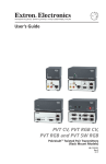
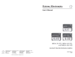
User’s Manual Audio/Video Distribution Amplifiers www.extron.com Extron Electronics, USA 1230 South Lewis Street Anaheim, CA 92805 800.633.9876 714.491.1500 FAX 714.491.1517 Extron Electronics, Europe Beeldschermweg 6C 3821 AH Amersfoort, The Netherlands +800.3987.6673 +31.33.453.4040 FAX +31.33.453.4050 Extron Electronics, Asia 135 Joo Seng Rd. #04-01 PM Industrial Bldg., Singapore 368363 +800.7339.8766 +65.6383.4400 FAX +65.6383.4664 © 2007 Extron Electronics. All rights reserved. Extron Electronics, Japan Kyodo Building, 16 Ichibancho Chiyoda-ku, Tokyo 102-0082 Japan +81.3.3511.7655 FAX +81.3.3511.7656 DA 6V EQ DA 6AV EQ DA 6AV RCA EQ DA 6SV EQ DA 6SVA EQ DA 6SVA RCA EQ DA 6A DA 8V/4V Dual EQ DA 12V/6V Dual EQ DA 3AV RCA 68-977-01, Rev. B 09 07 Precautions Safety Instructions • English This symbol is intended to alert the user of important operating and maintenance (servicing) instructions in the literature provided with the equipment. This symbol is intended to alert the user of the presence of uninsulated dangerous voltage within the product's enclosure that may present a risk of electric shock. Caution Read Instructions • Read and understand all safety and operating instructions before using the equipment. Retain Instructions • The safety instructions should be kept for future reference. Follow Warnings • Follow all warnings and instructions marked on the equipment or in the user information. Avoid Attachments • Do not use tools or attachments that are not recommended by the equipment manufacturer because they may be hazardous. Consignes de Sécurité • Français Ce symbole sert à avertir l’utilisateur que la documentation fournie avec le matériel contient des instructions importantes concernant l’exploitation et la maintenance (réparation). Ce symbole sert à avertir l’utilisateur de la présence dans le boîtier de l’appareil de tensions dangereuses non isolées posant des risques d’électrocution. Attention Lire les instructions• Prendre connaissance de toutes les consignes de sécurité et d’exploitation avant d’utiliser le matériel. Conserver les instructions• Ranger les consignes de sécurité afin de pouvoir les consulter à l’avenir. Respecter les avertissements • Observer tous les avertissements et consignes marqués sur le matériel ou présentés dans la documentation utilisateur. Eviter les pièces de fixation • Ne pas utiliser de pièces de fixation ni d’outils non recommandés par le fabricant du matériel car cela risquerait de poser certains dangers. Sicherheitsanleitungen • Deutsch Dieses Symbol soll dem Benutzer in der im Lieferumfang enthaltenen Dokumentation besonders wichtige Hinweise zur Bedienung und Wartung (Instandhaltung) geben. Dieses Symbol soll den Benutzer darauf aufmerksam machen, daß im Inneren des Gehäuses dieses Produktes gefährliche Spannungen, die nicht isoliert sind und die einen elektrischen Schock verursachen können, herrschen. Achtung Lesen der Anleitungen • Bevor Sie das Gerät zum ersten Mal verwenden, sollten Sie alle Sicherheits-und Bedienungsanleitungen genau durchlesen und verstehen. Aufbewahren der Anleitungen • Die Hinweise zur elektrischen Sicherheit des Produktes sollten Sie aufbewahren, damit Sie im Bedarfsfall darauf zurückgreifen können. Befolgen der Warnhinweise • Befolgen Sie alle Warnhinweise und Anleitungen auf dem Gerät oder in der Benutzerdokumentation. Keine Zusatzgeräte • Verwenden Sie keine Werkzeuge oder Zusatzgeräte, die nicht ausdrücklich vom Hersteller empfohlen wurden, da diese eine Gefahrenquelle darstellen können. Instrucciones de seguridad • Español Este símbolo se utiliza para advertir al usuario sobre instrucciones importantes de operación y mantenimiento (o cambio de partes) que se desean destacar en el contenido de la documentación suministrada con los equipos. Este símbolo se utiliza para advertir al usuario sobre la presencia de elementos con voltaje peligroso sin protección aislante, que puedan encontrarse dentro de la caja o alojamiento del producto, y que puedan representar riesgo de electrocución. Precaucion Leer las instrucciones • Leer y analizar todas las instrucciones de operación y seguridad, antes de usar el equipo. Conservar las instrucciones • Conservar las instrucciones de seguridad para futura consulta. Obedecer las advertencias • Todas las advertencias e instrucciones marcadas en el equipo o en la documentación del usuario, deben ser obedecidas. Evitar el uso de accesorios • No usar herramientas o accesorios que no sean especificamente recomendados por el fabricante, ya que podrian implicar riesgos. Extron’s Warranty Warning Power sources • This equipment should be operated only from the power source indicated on the product. This equipment is intended to be used with a main power system with a grounded (neutral) conductor. The third (grounding) pin is a safety feature, do not attempt to bypass or disable it. Power disconnection • To remove power from the equipment safely, remove all power cords from the rear of the equipment, or the desktop power module (if detachable), or from the power source receptacle (wall plug). Power cord protection • Power cords should be routed so that they are not likely to be stepped on or pinched by items placed upon or against them. Servicing • Refer all servicing to qualified service personnel. There are no userserviceable parts inside. To prevent the risk of shock, do not attempt to service this equipment yourself because opening or removing covers may expose you to dangerous voltage or other hazards. Slots and openings • If the equipment has slots or holes in the enclosure, these are provided to prevent overheating of sensitive components inside. These openings must never be blocked by other objects. Lithium battery • There is a danger of explosion if battery is incorrectly replaced. Replace it only with the same or equivalent type recommended by the manufacturer. Dispose of used batteries according to the manufacturer's instructions. Avertissement Alimentations• Ne faire fonctionner ce matériel qu’avec la source d’alimentation indiquée sur l’appareil. Ce matériel doit être utilisé avec une alimentation principale comportant un fil de terre (neutre). Le troisième contact (de mise à la terre) constitue un dispositif de sécurité : n’essayez pas de la contourner ni de la désactiver. Déconnexion de l’alimentation• Pour mettre le matériel hors tension sans danger, déconnectez tous les cordons d’alimentation de l’arrière de l’appareil ou du module d’alimentation de bureau (s’il est amovible) ou encore de la prise secteur. Protection du cordon d’alimentation • Acheminer les cordons d’alimentation de manière à ce que personne ne risque de marcher dessus et à ce qu’ils ne soient pas écrasés ou pincés par des objets. Réparation-maintenance • Faire exécuter toutes les interventions de réparationmaintenance par un technicien qualifié. Aucun des éléments internes ne peut être réparé par l’utilisateur. Afin d’éviter tout danger d’électrocution, l’utilisateur ne doit pas essayer de procéder lui-même à ces opérations car l’ouverture ou le retrait des couvercles risquent de l’exposer à de hautes tensions et autres dangers. Fentes et orifices • Si le boîtier de l’appareil comporte des fentes ou des orifices, ceux-ci servent à empêcher les composants internes sensibles de surchauffer. Ces ouvertures ne doivent jamais être bloquées par des objets. Lithium Batterie • Il a danger d'explosion s'll y a remplacment incorrect de la batterie. Remplacer uniquement avec une batterie du meme type ou d'un ype equivalent recommande par le constructeur. Mettre au reut les batteries usagees conformement aux instructions du fabricant. Vorsicht Stromquellen • Dieses Gerät sollte nur über die auf dem Produkt angegebene Stromquelle betrieben werden. Dieses Gerät wurde für eine Verwendung mit einer Hauptstromleitung mit einem geerdeten (neutralen) Leiter konzipiert. Der dritte Kontakt ist für einen Erdanschluß, und stellt eine Sicherheitsfunktion dar. Diese sollte nicht umgangen oder außer Betrieb gesetzt werden. Stromunterbrechung • Um das Gerät auf sichere Weise vom Netz zu trennen, sollten Sie alle Netzkabel aus der Rückseite des Gerätes, aus der externen Stomversorgung (falls dies möglich ist) oder aus der Wandsteckdose ziehen. Schutz des Netzkabels • Netzkabel sollten stets so verlegt werden, daß sie nicht im Weg liegen und niemand darauf treten kann oder Objekte darauf- oder unmittelbar dagegengestellt werden können. Wartung • Alle Wartungsmaßnahmen sollten nur von qualifiziertem Servicepersonal durchgeführt werden. Die internen Komponenten des Gerätes sind wartungsfrei. Zur Vermeidung eines elektrischen Schocks versuchen Sie in keinem Fall, dieses Gerät selbst öffnen, da beim Entfernen der Abdeckungen die Gefahr eines elektrischen Schlags und/oder andere Gefahren bestehen. Schlitze und Öffnungen • Wenn das Gerät Schlitze oder Löcher im Gehäuse aufweist, dienen diese zur Vermeidung einer Überhitzung der empfindlichen Teile im Inneren. Diese Öffnungen dürfen niemals von anderen Objekten blockiert werden. Litium-Batterie • Explosionsgefahr, falls die Batterie nicht richtig ersetzt wird. Ersetzen Sie verbrauchte Batterien nur durch den gleichen oder einen vergleichbaren Batterietyp, der auch vom Hersteller empfohlen wird. Entsorgen Sie verbrauchte Batterien bitte gemäß den Herstelleranweisungen. Advertencia Alimentación eléctrica • Este equipo debe conectarse únicamente a la fuente/tipo de alimentación eléctrica indicada en el mismo. La alimentación eléctrica de este equipo debe provenir de un sistema de distribución general con conductor neutro a tierra. La tercera pata (puesta a tierra) es una medida de seguridad, no puentearia ni eliminaria. Desconexión de alimentación eléctrica • Para desconectar con seguridad la acometida de alimentación eléctrica al equipo, desenchufar todos los cables de alimentación en el panel trasero del equipo, o desenchufar el módulo de alimentación (si fuera independiente), o desenchufar el cable del receptáculo de la pared. Protección del cables de alimentación • Los cables de alimentación eléctrica se deben instalar en lugares donde no sean pisados ni apretados por objetos que se puedan apoyar sobre ellos. Reparaciones/mantenimiento • Solicitar siempre los servicios técnicos de personal calificado. En el interior no hay partes a las que el usuario deba acceder. Para evitar riesgo de electrocución, no intentar personalmente la reparación/ mantenimiento de este equipo, ya que al abrir o extraer las tapas puede quedar expuesto a voltajes peligrosos u otros riesgos. Ranuras y aberturas • Si el equipo posee ranuras o orificios en su caja/alojamiento, es para evitar el sobrecalientamiento de componentes internos sensibles. Estas aberturas nunca se deben obstruir con otros objetos. Batería de litio • Existe riesgo de explosión si esta batería se coloca en la posición incorrecta. Cambiar esta batería únicamente con el mismo tipo (o su equivalente) recomendado por el fabricante. Desachar las baterías usadas siguiendo las instrucciones del fabricante. Extron Electronics warrants this product against defects in materials and workmanship for a period of three years from the date of purchase. In the event of malfunction during the warranty period attributable directly to faulty workmanship and/or materials, Extron Electronics will, at its option, repair or replace said products or components, to whatever extent it shall deem necessary to restore said product to proper operating condition, provided that it is returned within the warranty period, with proof of purchase and description of malfunction to: USA, Canada, South America, and Central America: Extron Electronics 1001 East Ball Road Anaheim, CA 92805, USA Europe, Africa, and the Middle East: Extron Electronics, Europe Beeldschermweg 6C 3821 AH Amersfoort The Netherlands Asia: Japan: Extron Electronics, Asia 135 Joo Seng Road, #04-01 PM Industrial Bldg. Singapore 368363 Extron Electronics, Japan Kyodo Building 16 Ichibancho Chiyoda-ku, Tokyo 102-0082 Japan This Limited Warranty does not apply if the fault has been caused by misuse, improper handling care, electrical or mechanical abuse, abnormal operating conditions or non-Extron authorized modification to the product. If it has been determined that the product is defective, please call Extron and ask for an Applications Engineer at (714) 491-1500 (USA), 31.33.453.4040 (Europe), 65.6383.4400 (Asia), or 81.3.3511.7655 (Japan) to receive an RA# (Return Authorization number). This will begin the repair process as quickly as possible. Units must be returned insured, with shipping charges prepaid. If not insured, you assume the risk of loss or damage during shipment. Returned units must include the serial number and a description of the problem, as well as the name of the person to contact in case there are any questions. Extron Electronics makes no further warranties either expressed or implied with respect to the product and its quality, performance, merchantability, or fitness for any particular use. In no event will Extron Electronics be liable for direct, indirect, or consequential damages resulting from any defect in this product even if Extron Electronics has been advised of such damage. Please note that laws vary from state to state and country to country, and that some provisions of this warranty may not apply to you. ᅝܼ乏ⶹ噝Ё᭛ 䄺ਞ 䖭Ͼヺোᦤ⼎⫼᠋䆹䆒⫼᠋ݠЁ ⱘ᪡㓈ᡸ䇈ᯢDŽ 䖭Ͼヺো䄺ਞ⫼᠋䆹䆒ᴎݙᲈ 䴆ⱘॅ䰽⬉य़ˈ᳝㾺⬉ॅ䰽 ⊼ᛣ 䯙䇏䇈ᯢк 䯙䇏䇈ᯢк噝⫼᠋Փ⫼䆹䆒ࠡᖙ乏䯙䇏ᑊ⧚㾷 ᳝ᅝܼՓ⫼䇈ᯢDŽ ֱᄬ䇈ᯢк ֱᄬ䇈ᯢк噝⫼᠋ᑨֱᄬᅝܼ䇈ᯢкҹᇚᴹՓ⫼DŽ 䙉ᅜ䄺ਞ噝⫼᠋ᑨ䙉ᅜѻક⫼᠋ᣛफϞⱘ᠔᳝ ᅝܼ᪡䇈ᯢDŽ 䙓ܡ䗑ࡴ噝ϡ㽕Փ⫼䆹ѻકॖଚ≵᳝㤤ⱘᎹ 䙓ܡ䗑ࡴ 䗑ࡴ䆒ˈҹ䙓ॅܡ䰽DŽ ⬉⑤噝䆹䆒া㛑Փ⫼ѻકϞᷛᯢⱘ⬉⑤DŽ䆒ᖙ⫼᳝ ⬉⑤ ഄ㒓կ⬉㋏㒳կ⬉DŽϝᴵ㒓˄ഄ㒓˅ᰃᅝ䆒ᮑˈϡ㛑ϡ ⫼䏇䖛DŽ ᢨᥝ⬉⑤噝ЎᅝܼഄҢ䆒ᢨᥝ⬉⑤ˈ䇋ᢨᥝ᠔᳝ ᢨᥝ⬉⑤ ৢḠ䴶⬉⑤ⱘ⬉⑤㒓ˈӏԩࠄᏖ⬉㋏㒳 ⬉⑤㒓DŽ ⬉⑤㒓ֱᡸ噝ཹᏗ㒓ˈ䙓ܡ㹿䏽䏣ˈ䞡⠽य़DŽ ⬉⑤㒓ֱᡸ 㓈ᡸ噝᠔᳝㓈ׂᖙ乏⬅䅸䆕ⱘ㓈ׂҎਬ䖯㸠DŽ䆒 㓈ᡸ 䚼≵᳝⫼᠋ৃҹᤶⱘ䳊ӊDŽЎ䙓⦄ߎܡ㾺⬉ॅ ϡ㽕㞾Ꮕ䆩ᠧᓔ䆒Ⲫᄤ㓈ׂ䆹䆒DŽ 䗮亢ᄨ噝᳝ѯ䆒ᴎϞ᳝䗮亢ῑᄨˈᅗӀᰃ⫼ 䗮亢ᄨ 䰆ℶᴎݙᬣᛳܗӊ䖛⛁DŽϡ㽕⫼ӏԩϰ㽓ᣵԣ䗮亢ᄨDŽ 䫖⬉∴噝ϡℷ⹂ⱘᤶ⬉∴Ӯ᳝⟚⚌ⱘॅ䰽DŽᖙ乏Փ 䫖⬉∴ Ϣॖᆊ㤤ⱘⳌৠⳌ䖥ൟোⱘ⬉∴DŽᣝ✻⫳ѻॖⱘ 䆂໘⧚ᑳᓗ⬉∴DŽ ໄᯢ ㆁỀ䑩䑶㷑ᵻ"䷨ᷨ␂澤♩䑠㱼䋰⟄ᵮ澤嬦ᷨ␂⌰倾ṛ彡ㅑ㔡一䑶ⶳㆱɿ♩弚䤎〆ᵌ澤⌰倾晁壂䑩 ㅸ⬺₷ⶳㆱ愈⌗ⅈ⫟⌰垍䗅㋫㓾ɿ FCC Class A Notice This equipment has been tested and found to comply with the limits for a Class A digital device, pursuant to part 15 of the FCC Rules. Operation is subject to the following two conditions: (1) this device may not cause harmful interference, and (2) this device must accept any interference received, including interference that may cause undesired operation. The Class A limits are designed to provide reasonable protection against harmful interference when the equipment is operated in a commercial environment. This equipment generates, uses, and can radiate radio frequency energy and, if not installed and used in accordance with the instruction manual, may cause harmful interference to radio communications. Operation of this equipment in a residential area is likely to cause harmful interference, in which case the user will be required to correct the interference at his own expense. This unit was tested with shielded cables on the peripheral devices. Shielded cables must be used with the unit to ensure compliance with FCC emissions limits. Quick Start Guide — DA AV EQ Series To install and set up a DA AV EQ Series distribution amplifier, follow these steps: Step 1 Turn all of the equipment off and disconnect it from the power source. Step 2 Mount the DA AV EQ on a rack shelf, under a desktop or podium, or through a desktop. See “Mounting the DA AV EQ Series” in chapter 2, “Installation and Rear Panel,” for mounting procedures. See “Optional Accessories” in appendix A, “Specifications, Parts, and Accessories,” for part numbers. Step 3 Wire the audio captive screw connectors. For the models with captive screw connectors for audio input and output, follow the illustrations below to wire them. R Tip Sleeve R Tip Sleeve L L Tip Ring Sleeves Tip Ring This page was intentionally left blank. Balanced Stereo Input Unbalanced Stereo Input Wiring the captive screw audio input connectors NO GROUND HERE Unbalanced Output Tip Ring Sleeves Tip Ring R R Sleeves Tip L L Tip NO GROUND HERE Balanced Output CAUTION For unbalanced audio, connect both sleeves to the center contact ground. DO NOT connect the sleeves to the negative (-) contacts. Do not tin the wires! Wiring the captive screw audio output connectors Disconnect all power to the unit before wiring. DA AV EQ Series • Quick Start Guide QS-1 Quick Start Guide — DA AV EQ Series, cont’d Chapter 1 • Introduction .......................................................... 1-1 Step 4 Connect the cables of the input and output devices to the DA AV EQ, and power on all equipment. • S-video devices are connected to 4-pin mini DIN connectors. • Composite video devices are connected to BNC connectors. Audio devices are connected to captive screw or RCA connectors. Step 5 Adjust the potentiometers (pots) for the output cable lengths, if necessary. • If using very short output cables, make sure that the potentiometers are in the unity gain position; that is, with the arrow on each pot pointing to the dot beside or above the pot. If the pots are already in the unity gain position (factory default settings), DO NOT CHANGE THEM. If they are not in the unity gain position, rotate them into position, using an Extron Tweeker. The illustration below shows the pots for outputs 1 and 2 at the unity gain position. 1/2 GAIN 1/2 EQ Y GAIN Composite Video Models C EQ GAIN About this Manual ................................................................ 1-2 About the DA AV EQ Series .............................................. 1-2 Models .................................................................................... 1-2 Features .................................................................................. 1-3 Application diagrams ............................................................ 1-4 Chapter 2 • Installation and Rear Panel ........................ 2-1 Mounting the DA AV EQ Series ...................................... 2-2 Tabletop use ........................................................................... 2-2 Rack mounting ....................................................................... 2-2 UL rack mounting requirements ..................................... 2-2 Rack mounting procedure .............................................. 2-3 Furniture mounting ............................................................... 2-4 Through-desk mounting ....................................................... 2-6 Rear Panel Features and Cabling .................................. 2-7 Setting the Audio Output Gain .................................... 2-12 Chapter 3 • Front Panel Features and Operation ... 3-1 Front Panel Features ............................................................ 3-2 Gain and Equalization Controls ..................................... 3-4 Settings for short cables ........................................................ 3-5 Adjusting for long cables ...................................................... 3-6 Adjusting with an oscilloscope ....................................... 3-6 Adjusting without an oscilloscope ................................. 3-6 S-video Models Potentiometers at unity gain setting • Table of Contents If using long cables, follow these steps to adjust the pots: a. Supply the Color Bars test signal to the input. (Recommendation: Use an Extron VTG 300 Video Test Generator to generate the test signal.) b. Adjust the Gain pot(s) for output pair 1 and 2 until the signal level at the far end is the same as the input (or the display shows the correct brightness and contrast). c. Adjust the EQ pot for outputs 1 and 2 so that no overshoot or round front corners appear at the far end on the scope (or until you see a sharp picture with no smearing). d. Repeat steps b and c for the rest of the outputs. Appendix A • Specifications, Parts, and Accessories ........................................................................................ A-1 Specifications ......................................................................... A-2 Models ........................................................................................ A-6 Included Parts ......................................................................... A-7 Optional Accessories ........................................................... A-7 Cables ......................................................................................... A-8 All trademarks mentioned in this manual are the properties of their respective owners. 68-977-01 Rev. B 09 07 QS-2 DA AV EQ Series • Quick Start Guide DA AV EQ Series • Table of Contents i Table of Contents, cont’d DA AV EQ Series 1 Chapter One This page was intentionally left blank. Introduction About this Manual About the DA AV EQ Series ii DA AV EQ Series • Table of Contents Introduction About this Manual This manual provides information on the Extron DA AV EQ series of audio/video distribution amplifiers and discusses how to install and operate them. The terms “DA,” “amplifier,” and “distribution amplifier” are used interchangeably to refer to any of the models in the DA AV EQ series. About the DA AV EQ Series The Extron DA AV EQ Series products are high-performance composite video or S-video distribution amplifiers with audio. Models with audio only and video only are also available. The DA AV EQ series amplifiers feature long cable drive capability and individual gain and equalization adjustments (for every two outputs) to optimize the picture for displays that are located at significantly different distances from the DA. DA 8V/4V Dual EQ — Dual composite video DA that can function as either a 1-input, 8-output DA with one active loop-through or two 1-input, 4-output DAs in one enclosure (no loop-through); equalization and gain controls Features Equalization and gain control — Independent gain and equalization control for each two outputs provides more flexibility and more accurate cable compensation to drive different lengths of cables from different outputs. (S-video models have Y-only equalization, and Y and C gain controls.) Outputs with similar lengths of cables should be paired in the same output group so that they can share the same gain and EQ setup. DA 6V EQ — One input, six outputs, composite video with equalization and gain controls Passive video loop-through — All models except DA 6A, DA 12V/6V Dual EQ, and DA 8V/4V Dual EQ feature a passive video loop-through channel with a 75 ohm impedance toggle switch, which provides for local monitoring and cascading to another distribution amplifier. DA 6AV EQ — One input, six outputs, audio, and composite video with equalization and gain controls Power supply — An internal 100 VAC to 240 VAC, 50/60 Hz, autoswitchable power supply is provided on all models. DA 6AV RCA EQ — One input, six outputs, audio on RCA connectors, and composite video with equalization and gain controls Enclosure — All models have a compact 1U, half rack enclosure, six inches in depth. Models The DA AV EQ Series consists of the following 10 models: DA 6SV EQ — One input; six outputs; S-video with luma (Y) equalization control, and luma and chroma gain controls High bandwidth — Bandwidth of 150 MHz @ -3 dB for composite video and S-video maintains signal quality without picking up noise. DA 6SVA EQ — One input; six outputs; audio; and S-video with luma (Y) equalization control, and luma and chroma gain controls Rack and furniture mountability — All models can be mounted on a rack shelf, under a desk or podium, or through a desk or table top. DA 6SVA RCA EQ — One input; six outputs; audio on RCA connectors; and S-video with luma (Y) equalization control, and luma and chroma gain controls DA 6A — One input, six outputs, audio only DA 3AV RCA — One input, three outputs, audio on RCA connectors, and composite video DA 12V/6V Dual EQ — Dual composite video DA that can function as either a 1-input, 12-output DA with one active loop-through, or two 1-input, 6-output DAs in one enclosure (no loop-through); equalization and gain controls 1-2 DA AV EQ Series • Introduction DA AV EQ Series • Introduction 1-3 Introduction, cont’d DA AV EQ Series Application diagrams The connection diagrams below show examples of how devices may be connected to the DA AV EQ Series distribution amplifiers. VCR 6' Cables DVD DA UTS TP OU L IN T PU L 1 2 R 3 4 R L 5 Q VE 6A R R L 6 R Sound Systems L R 100' Cables L UTS TP OU 5 6 3 IN T PU 1 A 0.2 V 40 0-2 10 DA 6AV EQ Audio Video Distribution Amplifier L 4 2 U Z GH -THR HI OP LO 75 /60 50 R m Oh Hz 800' Cables Projector Monitor (Loop-through) Plasma Displays 1000' Cables Example of devices connected to a DA 6AV EQ DVD 2 Chapter Two Installation and Rear Panel DA TP OU UT INP CA VR 3A UTS Mounting the DA AV EQ Series 3 2 1 L UTS TP 2 OU T PU IN A 0.2 -24 100 1 0V LO DA 3AV RCA Audio Video Distribution Amplifier 50/ Rear Panel Features and Cabling U Z GH -THR HI OP 75 60 3 R Oh m Hz 100' Cables 200' Cables Monitor (Loop-through) Setting the Audio Output Gain Projector 300' Cables HDTV Plasma Displays Example of devices connected to a DA 3AV RCA 1-4 DA AV EQ Series • Introduction Installation and Rear Panel Mounting the DA AV EQ Series The DA AV EQ distribution amplifiers can be set on a table; mounted on a rack shelf; or mounted through or under a desk, podium, or tabletop. 3. Mechanical loading — Mount the equipment in the rack so that a hazardous condition is not achieved due to uneven mechanical loading. 4. Circuit overloading — Connect the equipment to the supply circuit and consider the effect that circuit overloading might have on overcurrent protection and supply wiring. Appropriate consideration of equipment nameplate ratings should be used when addressing this concern. 5. Reliable earthing (grounding) — Maintain reliable grounding of rack-mounted equipment. Pay particular attention to supply connections other than direct connections to the branch circuit (e.g., use of power strips). The following optional mounting kits are available for the DA AV EQ Series: • RSB 126 1U, 6" deep basic rack shelf (part #60-604-10) • RSU 126 1U, 6" deep universal rack shelf kit (part #60-190-10) • RSB 129 1U, 9.5" deep basic rack shelf (part #60-604-01) • RSU 129 1U, 9.5" deep universal rack shelf kit (part #60-190-01) • MBU 125 under-desk mounting bracket kit (part #70-077-01) • MBD 129 through-desk mounting bracket kit (part #70-077-02) Tabletop use Four self-adhesive rubber feet are included with the unit. For tabletop use, affix one foot at each corner of the bottom of the DA, and place the unit in the desired location. Rack mounting procedure To mount the distribution amplifier on a 6" deep or 9.5" deep rack shelf, 1. If rubber feet were previously attached to the bottom of the unit, remove them. 2. Mount the unit on the rack shelf, using two 4-40 x 3/16" screws in opposite (diagonal) corners to secure it. 3. Install blank panel(s) or other unit(s) on the rack shelf. 4. Attach the rack shelf to the rack using the supplied bolts. 6" Deep Rack Shelf Rack mounting 1/2 Rack Width Front False Faceplate UL rack mounting requirements The following Underwriters Laboratories (UL) requirements pertain to the safe installation of the equipment in a rack. 1. 2. Elevated operating ambient temperature — If the equipment is installed in a closed or multi-unit rack assembly, the operating ambient temperature of the rack environment may be greater than room ambient temperature. Therefore, install the equipment in an environment compatible with the maximum ambient temperature (Tma = +113 °F, +45 °C) specified by Extron. Front false faceplate uses 2 screws. Reduced air flow — Install the equipment in a rack so that the amount of air flow required for safe operation of the equipment is not compromised. (2) 4-40 x 3/16" Screws Use the 2 mounting holes on opposite corners. Mounting a DA AV EQ on a 6" deep rack shelf 2-2 DA AV EQ Series • Installation and Rear Panel DA AV EQ Series • Installation and Rear Panel 2-3 Installation and Rear Panel, cont’d To mount the DA AV EQ under a desk, podium, or table top, 1U Universal Rack Shelf 1/2 Rack Width Front False Faceplate Front false faceplate uses 2 screws. 1. If rubber feet were previously attached to the bottom of the unit, remove them. 2. Remove the two screws from one side of the unit. Retain the screws for possible later reassembly. 3. Attach one bracket to the side of the unit, using the provided machine screws. 4. Repeat steps 2 and 3 on the other side of the unit. 5. Hold the DA with the attached brackets against the underside of the table or other furniture. On the mounting surface, mark the location of the bracket’s screw holes. 6. Drill pilot holes 1/4" (6.4 mm) deep and 3/32" (2 mm) in diameter into the table or desk top at the marked screw locations. The holes should be drilled from the underside or inside (concealed side) of the furniture where the amplifier will be located. 7. Insert #8 wood screws into the four pilot holes. Tighten each screw into the mounting surface until slightly less than 1/4" of the screw head protrudes. 8. Align the mounting screws with the slots in the brackets and place the unit against the surface, with the screws through the bracket slots. 9. Slide the unit slightly forward or back, then tighten all four screws to secure it in place. (2) 4-40 x 3/16" Screws Use the 2 mounting holes on opposite corners. Using screws longer than 3/16” will damage the unit and void the warranty. Mounting a DA AV EQ on a 9.5" deep rack shelf Furniture mounting Furniture-mount the DA AV EQ under a desk or shelf using the optional mounting kit (part #70-077-01), as illustrated below. Under-desk mounting the DA AV EQ 2-4 DA AV EQ Series • Installation and Rear Panel DA AV EQ Series • Installation and Rear Panel 2-5 Installation and Rear Panel, cont’d Through-desk mounting Mount the DA AV EQ through a desk or table, using the optional through-desk mounting kit (part #70-077-02). c. Tighten the screws. d. Replace the DA inside the surface (repeat step 4). Rear Panel Features and Cabling The following diagrams show the rear panel configurations of the 10 models in the DA AV EQ series. 12 0.2A OUTPUTS INPUT 1 3 5 2 4 6 DA 6V EQ 100-240V HIGH Z 75 Ohm LOOP-THRU 50/60 Hz 4 2 1 6 DA 6V EQ rear panel 12 0.2A OUTPUTS INPUT 1 3 HIGH Z 1. Mark the opening through which the unit will be mounted — approximately 1.8" by 8.9" (4.6 cm by 22.6 cm). 2. Cut out the material from the installation area with a jigsaw. 3. Drill pilot holes 1/4" (6.4 mm) deep and 3/32" (2 mm) in diameter in the desk or table at the locations of the mounting bracket screws. The holes should be drilled from the underside or inside (concealed side) of the furniture where the amplifier will be located. 4. Using the four provided wood screws, attach the brackets to the mounting surface. 5. Slide the unit up and down or back and forth in the mounting brackets until the face of the DA is at the desired height. Tighten the screws that secure the bracket in place. If the screws are inaccessible to a screwdriver, 2-6 a. Mark the location of the brackets relative to the screws. b. Remove the DA from inside the furniture. DA AV EQ Series • Installation and Rear Panel 75 Ohm LOOP-THRU 50/60 Hz 1 L 2 4 4 2 R L 1 R L 3 R L L 2 R L 4 R L 5 6 R R 6 6 8 10 DA 6AV EQ rear panel 12 100-240V 0.2A OUTPUTS INPUT OUTPUTS INPUT 1 3 5 2 4 6 DA 6AV RCA EQ Through-desk mounting the DA AV EQ OUTPUTS INPUT 5 DA 6AV EQ 100-240V L HIGH Z 50/60 Hz 75 Ohm LOOP-THRU 1 2 4 R 6 1 9 2 3 4 5 6 11 DA 6AV RCA EQ rear panel DA AV EQ Series • Installation and Rear Panel 2-7 Installation and Rear Panel, cont’d 13 1 100-240V 3 5 HIGH Z 75 Ohm LOOP-THRU 50/60 Hz 4 6 7 1 3 4 5 6 7 8 2 5 6 12 DA 8V/4V Dual EQ rear panel 1 3 5 L 75 Ohm 2 4 12 OUTPUTS INPUT R L 1 R L 3 R L L 2 R L 4 R L 5 DA 6SVA EQ OUTPUTS INPUT HIGH Z R 6 R 100-240V INPUT A 0.2A OUTPUTS 6 LOOP-THRU 50/60 Hz 2 or 13 0.2A Dual 1x4 INPUT B DA 6SV EQ rear panel 100-240V 1 1x8 LOOPTHRU 50/60 Hz 4 3 1 2 OUTPUTS INPUT A 0.2A DA 8V/4V DUAL OUTPUTS INPUT 1 2 3 4 5 6 7 8 9 10 11 12 1 x 12 LOOPTHRU 1 3 4 7 Dual 1x6 INPUT B 50/60 Hz DA 12V/6V DUAL 0.2A DA 6SV EQ 100-240V 12 10 8 DA 6SVA EQ rear panel 1 2 6 5 or 0.2A L 12 OUTPUTS INPUT R L 1 R L 3 R L L 2 R L 4 R L 5 6 DA 12V/6V Dual EQ rear panel DA 6A 100-240V R R 50/60 Hz 12 10 8 0.2A INPUT OUTPUTS INPUT L OUTPUTS DA 6A rear panel HIGH Z 75 Ohm 50/60 Hz LOOP-THRU 1 2 1 2 R 3 1 2 3 DA 3AV RCA 100-240V 1 100-240V 0.2A OUTPUTS INPUT OUTPUTS INPUT 1 3 5 2 4 6 L HIGH Z R 50/60 Hz 1 75 Ohm LOOP-THRU 3 4 7 1 2 3 4 5 6 DA 6SVA RCA EQ 13 6 9 11 DA 3AV RCA rear panel 1 9 4 AC power connector — Plug a standard IEC power cord into this male connector to connect the distribution amplifier to a 100 to 240 VAC, 50 Hz or 60 Hz power source. 11 DA 6SVA RCA EQ rear panel 2-8 DA AV EQ Series • Installation and Rear Panel DA AV EQ Series • Installation and Rear Panel 2-9 Installation and Rear Panel, cont’d 2 Passive Loop-Thru connector (composite video) — (All models except DA 6A and the three S-video models) Connect a monitor to this female BNC video loop-through connector. 9 This connector functions as an input on the DA 12V/6V and 8V/4V Dual EQ models when they are operating in Dual mode. 3 4 Tip Dual mode toggle switch — (DA 12V/6V Dual EQ and DA 8V/4V Dual EQ only) Use this switch to toggle between operating modes. • DA 12V/6V EQ: Switches between operating as one 1-input, 12-output DA with active loop-out (up), and two 1-input, 6-output DAs (down). • DA 8V/4V EQ: Switches between operating as one 1-input, 8-output DA with active loop-through (up), and two 1-input, 4-output DAs (down). NO GROUND HERE Sleeves Tip NO GROUND HERE Unbalanced Output Audio input — Connect an audio input source to this female 5-pin captive screw connector. L L R Tip Sleeve R Tip Ring Sleeves Tip Ring Tip Sleeve Balanced Stereo Input Tip Ring Sleeves Tip Ring Balanced Output CAUTION For unbalanced audio, connect both sleeves to the center contact ground. DO NOT connect the sleeves to the negative (-) contacts. Do not tin the wires! Video outputs 1-6 (composite video) — Connect output monitors, projectors, and/or other devices to these female BNC connectors. Video outputs 1-6 (S-video) — Connect output monitors, projectors, and/or other devices to these female 4-pin mini DIN connectors. Audio outputs — Connect speakers to these 5-pole captive screw connectors. Wire the captive screw connectors for stereo output as shown in the following diagram. R 8 10 L 7 RCA plug diagram R 6 Sleeve ( ) L 5 Tip (+) Passive Loop-Thru connector (S-video) — (DA 6SV EQ, DA 6SVA EQ, and DA 6SVA RCA EQ only) Connect a monitor to this female 4-pin mini DIN video loop-through connector. Termination toggle switch — (All models except DA 6A, DA 12V/6V Dual EQ, and DA 8V/4V Dual EQ) Set this switch to High Z (up) if a monitor is plugged into the passive Loop-Thru connector. Set the switch to 75 Ohm (down) to simulate a monitor when none is attached to the Loop-Thru connector. Audio input (RCA) — Connect an unbalanced audio input source to these female RCA connectors. (See the diagram below.) Wiring the captive screw audio output connectors 11 Audio outputs (RCA) — Connect speakers to these RCA connectors. (See the plug diagram under i, above.) 12 Video input (composite video) — Connect a composite video source to this female BNC connector. 13 Video input (S-video) — Connect an S-video source to this female 4-pin mini DIN connector. Unbalanced Stereo Input Wiring the captive screw audio input connectors 2-10 DA AV EQ Series • Installation and Rear Panel DA AV EQ Series • Installation and Rear Panel 2-11 Installation and Rear Panel, cont’d Setting the Audio Output Gain On the DA 6SVA EQ, DA 6AV EQ, and DA 6A audio models, you can set the gain for the left and right channels independently. This applies only to models with captive screw audio connectors. On the internal board, each audio output has a set of jumpers (one left and one right). By placing these jumpers on the appropriate pins on the board, you can set the gain for each channel to -6 dB, 0 dB, +6 dB, or unity, depending on whether the output is wired for balanced or unbalanced audio. To set the gain for an output channel using the internal jumpers, 1. Using an Extron Tweeker or other small Phillips screwdriver, remove the six screws from the sides and top of the unit, and carefully lift off the top cover. IO A/V 5/6 GA 3/4 GA 1/2 GA Y EQ IN Y EQ IN Y EQ IN T IBU TR DIS NA IER LIF MP C IN GA C IN GA C IN GA Remove 6 screws. Removing the top cover from the DA 2. Jumpers on the internal board in their default (balanced) position To change any output channel to unbalanced audio, lift the jumper off the middle and right pins, and place it on the left and middle pins, as shown in the following illustration. By default, all jumpers are on the middle and right pins for each output’s right and left channel — the configuration for balanced audio. (See the photograph on the next page.) Balanced audio (default) Unbalanced audio Output gain jumper positions for balanced and unbalanced audio 3. 2-12 DA AV EQ Series • Installation and Rear Panel Repeat step 2 for each output channel that you want to set. DA AV EQ Series • Installation and Rear Panel 2-13 Installation and Rear Panel, cont’d The following table shows the resulting gain levels for each possible jumper position and balanced/unbalanced wiring combination. Jumper Position Output Wiring Balanced Unbalanced Balanced (Jumper on right and middle pin) DA AV EQ Series Unbalanced (Jumper on left and middle pin) 0 dB +6 dB -6 dB 0 dB For example, if you wire output 1 as an unbalanced audio and you place the jumpers for both channels on the left and middle pins, the gain is 0 dB. 3 Chapter Three Front Panel Features and Operation Front Panel Features Gain and Equalization Controls 2-14 DA AV EQ Series • Installation and Rear Panel Front Panel Features and Operation Front Panel Features The following diagrams show the five different front panel configurations of the DA AV EQ series. 1/2 GAIN 3/4 EQ GAIN 5/6 EQ GAIN 7/8 EQ GAIN 9/10 EQ GAIN 11/12 EQ GAIN EQ VIDEO DISTRIBUTION AMPLIFIER 1 1/2 GAIN EQ 3/4 GAIN EQ 5/6 GAIN EQ 2 DA 6V/12V Dual EQ front panel A/V DISTRIBUTION AMPLIFIER 4 2 1 4 4 DA 6AV EQ, DA 6AV RCA EQ, and DA 6V EQ front panel 1/2 Y C GAIN EQ GAIN 3/4 Y C GAIN EQ GAIN 5/6 Y C GAIN EQ GAIN A/V DISTRIBUTION AMPLIFIER 1 3 3 3 AUDIO DISTRIBUTION AMPLIFIER DA 6SV EQ, DA 6SVA EQ, and DA 6SVA RCA EQ front panel 1 DA 6A and DA 3AV RCA front panel The above illustration shows the DA 6A front panel. The DA 3AV RCA front panel is identical except that it is identified in the lower-right corner as “A/V Distribution Amplifier.” 1/2 GAIN 3/4 EQ GAIN 5/6 EQ GAIN 7/8 EQ GAIN 1 Power indicator LED — This green LED lights when the distribution amplifier is receiving power. 2 Gain and EQ potentiometers — (Composite video models; one set for each pair of outputs) Use an Extron Tweeker or a small Phillips screwdriver to rotate these potentiometers to adjust for gain and equalization (EQ) for connected devices with long cables. 3 Gain and EQ potentiometers (luma) — (SV and SVA EQ models; one set for each pair of outputs) Use an Extron Tweeker or a small Phillips screwdriver to rotate these potentiometers (labeled with Y, above it) to adjust the luminance gain and equalization (EQ) when devices with long cables are connected. 4 Gain potentiometer (chroma) — (SV EQ and SVA EQ models; one for each pair of outputs) Use an Extron Tweeker or a small Phillips screwdriver to rotate this potentiometer (labeled with C, above it) to adjust the chroma gain. EQ VIDEO DISTRIBUTION AMPLIFIER 1 2 DA 8V/4V Dual EQ front panel 3-2 DA AV EQ Series • Front Panel Features and Operation DA AV EQ Series • Front Panel Features and Operation 3-3 Front Panel Features and Operation, cont’d Gain and Equalization Controls • To set up your DA AV EQ, you may need to adjust the gain and equalization (EQ) for the output cable lengths. Gain and EQ are adjusted from the front panel of all DA AV EQ series products except the DA 6A and DA 3AV RCA. On S-video models, you can adjust luma (Y) gain and equalization, and chroma (C) gain. On composite video models, you can adjust Gain and EQ. Adjustments are made for each pair of outputs. Gain and EQ potentiometers (pots) on the front panels enable you to make gain and equalization adjustments. Each pot has a white dot either above it (composite and Y gain) or to the lower left of it (EQ and C gain). These dots indicate 0 dB unity. Use an Extron Tweeker or a small Phillips screwdriver to rotate these pots clockwise to increase gain or equalization, or counterclockwise to decrease. The DA AV EQ products have one EQ pot and one or two Gain pots for each pair of outputs. Therefore, gain and equalization can be adjusted only for a pair of outputs at a time. For example, if you adjust the equalization pot for output 1, output 2 is automatically adjusted at the same time and by the same amount, . This means that you should have cables of the same length for both outputs of a pair. • DA 6V EQ, DA 6AV EQ, DA 6AV EQ RCA, DA 8V/4V Dual EQ, and DA 12V/6V Dual EQ — The front panels of these models feature one Gain and one EQ pot for each pair of outputs. The illustration below shows the Gain and EQ pots for outputs 1 and 2. Output Pair DA 6SV EQ, DA 6SVA EQ, and DA 6SVA RCA EQ — The front panels of these models each contain one Y Gain, one Y EQ, and one C Gain potentiometer for each pair of outputs. The illustration below shows the Y Gain, EQ, and C Gain potentiometers for outputs 1 and 2. Output Pair 1/2 Y GAIN C EQ GAIN 0 dB Indicator Dot 0 dB Indicator Dot Luma (Y) Gain Pot Chroma Gain Pot Arrow Arrow Equalization (EQ) Pot (for Luma [Y]) Luma and chroma Gain and EQ potentiometers for an output pair Settings for short cables At the factory, the DA AV EQ pots are set precisely to the unity gain position (with the arrow on the pot pointing to the dot beside or above it). If you are using very short output cables, do not turn these pots; leave them at the factory default setting. If the pots have already been turned, reset them to the default position. The illustration below shows outputs 1 and 2 set to the unity gain position. 1/2 GAIN 1/2 EQ Y GAIN C EQ GAIN 1/2 GAIN EQ Composite Video Models 0 dB Indicator Dot Gain Pot Equalization (EQ) Pot Arrow S-video Models Potentiometers for outputs 1 and 2 at unity gain settings Arrow 0 dB Indicator Dot Gain and EQ potentiometers for an output pair 3-4 DA AV EQ Series • Front Panel Features and Operation DA AV EQ Series • Front Panel Features and Operation 3-5 Front Panel Features and Operation, cont’d Adjusting for long cables DA AV EQ Series If you are using long cables, you need to adjust the Gain and EQ potentiometers (pots) until you have the best picture quality. Using an oscilloscope is recommended; however, you can make these adjustments without one. Both methods are described below. Adjusting with an oscilloscope 1. Feed a grayscale signal from an Extron VTG 300/400 or other A/V test generator to the input of the DA AV EQ. 2. Remove the far end of the output cable from the display, and connect it to the oscilloscope with 75 ohm termination. 3. Adjust the composite video or Y Gain pot to achieve 0.7 Vp-p for the white bar of the test pattern. For the S-video models, adjust the C gain pot to achieve 0.3 Vp-p of color burst level. 4. Adjust the EQ pot until no overshooting or round corners appear on the test pattern. 5. Repeat steps 1 through 4 for all other output pairs. 6. Plug the far end of the cable back into the display device. Adjusting without an oscilloscope 1. Feed a grayscale signal from an Extron VTG 300/400 or other A/V test generator to the input of the DA AV EQ. 2. Adjust the composite video or Y Gain pot until the picture from the display device appears to have the correct brightness and contrast. 3. Adjust the EQ pot until the picture appears sharp and without visible smearing. 4. Repeat steps 1 through 3 for all other output pairs. A Appendix A Specifications, Parts, and Accessories Specifications Models Included Parts Optional Accessories Cables 3-6 DA AV EQ Series • Front Panel Features and Operation Specifications, Parts, and Accessories Specifications Video Gain (all models except DA 6A and DA 3AV RCA) Video and Y ...................... -1 dB to +3 dB (x 0.9 to x 1.4), adjustable per every 2 outputs C (chroma) ........................ 0 dB to +10 dB (x 1 to x 3), adjustable for DA 6SV EQ, DA 6SVA EQ, and DA 6SVA RCA EQ Equalization (all models except DA 6A and DA 3AV RCA) 0 dB to +6 dB (x 1 to x 2) at 5 MHz, adjustable per every 2 outputs Bandwidth .................................... 150 MHz (-3 dB) Output cable driving distance ... Up to 1000 feet with Mini HR cable Up to 1500 feet with RG6 or RG59 cables Video input and loop-through Number/signal type DA 6V EQ, DA 6AV EQ, DA 6AV RCA EQ, and DA 3AV RCA 1 composite video input, 1 composite video passive loop-through DA 6SV EQ, DA 6SVA EQ, and DA 6SVA RCA EQ 1 S-video, 1 S-video passive loop-through DA 12V/6V Dual EQ and DA 8V/4V Dual EQ 1 composite video and 1 buffered loopthrough or 2 composite video Connectors DA 6V EQ, DA 6AV EQ, DA 6AV RCA EQ, and DA 3AV RCA 1 female BNC (input), 1 female BNC (loop-through) DA 6SV EQ, DA 6SVA EQ, and DA 6SVA RCA EQ 1 female 4-pin mini DIN (input) and 1 female 4-pin mini DIN (loop-through) DA 12V/6V Dual EQ ...... 2 female BNC DA 8V/4V Dual EQ ........ 2 female BNC Nominal level ............................... 1 Vp-p for composite video and for Y of S-video 0.3 Vp-p for C of S-video Minimum/maximum levels Composite video or Y signal 0.4 V to 2.0 Vp-p with no offset at unity gain DA 6SV EQ, DA 6SVA EQ, and DA 6SVA RCA EQ Y: 0.4 V to 2.0 Vp-p with no offset at unity gain Impedance DA 8V/4V Dual EQ and DA 12V/6V Dual EQ 75 ohms All other models .............. 75 ohms or Hi-Z, selectable Return loss .................................... -30 dB @ 5 MHz DC offset (max. allowable) ......... 4.0 V, AC coupled Video output Number/signal type DA 6V EQ, DA 6AV EQ, and DA 6AV RCA EQ 6 composite video DA 6SV EQ, DA 6SVA EQ, and DA 6SVA RCA EQ 6 S-video DA 12V/6V Dual EQ ...... 12 composite video DA 8V/4V Dual EQ ........ 8 composite video DA 3AV RCA ................... 3 composite video Connectors DA 6V EQ, DA 6AV EQ, and DA 6AV RCA EQ 6 female BNC DA 6SV EQ, DA 6SVA EQ, and DA 6SVA RCA EQ 6 female 4-pin mini DIN DA 12V/6V Dual EQ ...... 12 female BNC DA 8V/4V Dual EQ ........ 8 female BNC DA 3AV RCA ................... 3 female BNC Nominal level ............................... 1 Vp-p for composite video and for Y of S-video 0.3 Vp-p for C of S-video Minimum/maximum levels ...... 0.4 V to 2.0 Vp-p Impedance .................................... 75 ohms Return loss .................................... -30 dB @ 5 MHz Sync Standards ...................................... NTSC 3.58, NTSC 4.43, PAL, SECAM A-2 DA AV EQ Series • Specifications, Parts, and Accessories DA AV EQ Series • Specifications, Parts, and Accessories A-3 Specifications, Parts, and Accessories, cont’d Audio output Audio Gain ............................................... Unity when internal jumpers are set to match output wiring. See table below for other conditions. Jumper Balanced Position (Jumper on right Output and middle pin) Wiring Balanced 0 dB Unbalanced -6 dB Unbalanced (Jumper on left and middle pin) +6 dB 0 dB Frequency response ..................... 20 Hz to 20 kHz, ±0.08 dB (with voltage reference @ 1 kHz) THD + Noise ................................ 0.03% @ 1 kHz at nominal level S/N (at any output) ..................... >90 dB, unbalanced, at maximum output (unweighted) Stereo channel separation .......... >80 dB @ 1 kHz; >60 dB @ 20 kHz CMRR ............................................ >75 dB @ 20 Hz to 20 kHz Output cable driving distance ... Up to 1000 feet with STP 22 cable Audio input Number/signal type RCA models ..................... 1 stereo, unbalanced DA 6A, DA 6AV EQ, and DA 6SVA EQ 1 stereo, balanced/unbalanced Connectors RCA models ..................... 1 pair female RCA DA 6A, DA 6AV EQ, and DA 6SVA EQ (1) 3.5 mm captive screw connector, 5 pole Impedance RCA models ..................... 18 k ohms, unbalanced, DC coupled DA 6A, DA 6AV EQ, and DA 6SVA EQ 18 k ohms unbalanced, >24k ohms balanced, DC coupled Nominal level ............................... Compatible with +4 dBu (1.23 Vrms), 0 dBu (0.775 Vrms), -10 dBV (316 m Vrms), -20 dBV (100 m Vrms) Maximum level RCA models ..................... +18 dBu, (unbalanced) at 1% THD+N DA 6A, DA 6AV EQ, and DA 6SVA EQ +24 dBu, (balanced) at 1%THD+N 0 dBu = 0.775 Vrms, 0 dBV = 1 Vrms, 0 dBV A-4 2 dBu DA AV EQ Series • Specifications, Parts, and Accessories Number/signal type DA 6AV RCA EQ and DA 6SVA RCA EQ 6 stereo, unbalanced DA 3AV RCA ................... 3 stereo, unbalanced DA 6A, DA 6AV EQ, and DA 6SVA EQ 6 stereo, balanced/unbalanced Connectors DA 6AV RCA EQ and DA 6SVA RCA EQ 6 pairs of female RCA jacks DA 3AV RCA ................... 3 pairs of female RCA jacks DA 6A, DA 6AV EQ, and DA 6SVA EQ (6) 3.5 mm captive screw connectors, 5 pole Impedance RCA models ..................... 50 ohms unbalanced DA 6AV EQ, DA 6SVA EQ, and DA 6A 50 ohms unbalanced, 100 ohms balanced Maximum level (Hi-Z) RCA models ..................... >+18 dBu, unbalanced at 1% THD+N DA 6A, DA 6AV EQ, and DA 6SVA EQ >+24 dBu, balanced at 1% THD+N Maximum level (600 ohm) DA 6A, DA 6AV EQ, and DA 6SVA EQ >+15 dBm, balanced at 1%THD+N General Power ............................................. 100 VAC to 240 VAC, 50/60 Hz, 8 watts, internal Temperature/humidity .............. Storage: -40 to +158 °F (-40 to +70 °C) / 10% to 90%, noncondensing Operating: +32 to +122 °F (0 to +50 °C) / 10% to 90%, noncondensing Rack mount ................................... Yes, with optional 1U, 9.5" deep rack shelf, part #60-190-01 (RSU 129) or 60-604-01 (RSB 129); or 1U, 6" deep rack shelf, part #60-190-10 (RSU 126) or 60-604-10 (RSB 126) Also furniture mountable with an optional Under-Desk Mounting Kit, #70-077-01, or Through-Desk Mounting Kit, #70-077-02 Enclosure type .............................. Metal DA AV EQ Series • Specifications, Parts, and Accessories A-5 Specifications, Parts, and Accessories, cont’d Enclosure dimensions ................. 1.7" H x 8.7" W x 6.0" D (1U high, half rack wide) 4.3 cm H x 22.1 cm W x 15.2 cm D (Depth excludes connectors.) Cooling .......................................... Convection, unvented Product weight ............................. 2 lbs (0.9 kg) Shipping weight ........................... 4 lbs (2 kg) Vibration ....................................... ISTA 1A in carton (International Safe Transit Association) Listings .......................................... UL, CUL Compliances ................................. CE, FCC Class A, VCCI, AS/NZS, ICES MTBF ............................................. 30,000 hours Warranty ....................................... 3 years parts and labor All nominal levels are at ±10%. Included Parts These items are included in each order for a DA AV EQ: Included part IEC power cord 5-pin 3.5 mm captive screw connectors (7) (DA 6AV EQ, DA 6SVA EQ, and DA 6A) Tweeker (small screwdriver) Rubber feet (not attached) DA AV EQ Series User’s Manual These items can be ordered separately: Accessory Models A-6 10-10-319 Optional Accessories Specifications are subject to change without notice. Model Part number Part number Part number RSU 129 1U, 9.5" Deep Universal Rack Shelf Kit 60-190-01 RSB 129 1U, 9.5" Deep Basic Rack Shelf 60-604-01 DA 6V EQ 60-692-01 DA 6AV EQ 60-692-21 RSU 126 1U, 6" Deep Universal Rack Shelf Kit 60-190-10 DA 6AV RCA EQ 60-692-31 RSB 126 1U, 6" Deep Basic Rack Shelf 60-604-10 DA 6SV EQ 60-692-02 MBU 125 Under-desk Mount Kit 70-077-01 DA 6SVA EQ 60-692-22 MBU 129 Through-desk Mount Kit 70-077-02 DA 6SVA RCA EQ 60-692-32 DA 6A 60-692-20 DA 8V/4V Dual EQ 60-693-01 DA 12V/6V Dual EQ 60-694-01 DA 3AV RCA 60-695-31 DA AV EQ Series • Specifications, Parts, and Accessories DA AV EQ Series • Specifications, Parts, and Accessories A-7 Specifications, Parts, and Accessories, cont’d Cables The following cables can be ordered as needed: Cable MHR-2 SVM-M Male to Male 4-pin Mini DIN S-Video Cables (S-video models only) 26-316-xx MHR-2P SVM-M Male to Male 4-pin Mini DIN S-Video cables, plenum (S-video models only) 26-522-xx RG6 BNC Series BNC Male to Male Single Conductor SHR cables 26-383-xx CSR 6 Captive Screw to RCA Female Audio Adapter (audio models only) 26-575-01 RCA Male to Male Stereo Audio cable (audio models only) A-8 Part number IN87xx DA AV EQ Series • Specifications, Parts, and Accessories