1
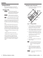
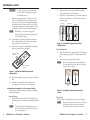
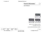
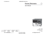
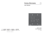
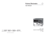
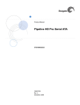
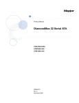
User’s Guide PCM 240 Projector Ceiling Mount www.extron.com Extron Electronics, USA Extron Electronics, Europe Extron Electronics, Asia Extron Electronics, Japan 1230 South Lewis Street Anaheim, CA 92805 USA 714.491.1500 Fax 714.491.1517 Beeldschermweg 6C 3821 AH Amersfoort The Netherlands +31.33.453.4040 Fax +31.33.453.4050 135 Joo Seng Road, #04-01 PM Industrial Building Singapore 368363 +65.6383.4400 Fax +65.6383.4664 Kyodo Building 16 Ichibancho Chiyoda-ku, Tokyo 102-0082 Japan +81.3.3511.7655 Fax +81.3.3511.7656 © 2006 Extron Electronics. All rights reserved. 68-1180-01 Rev. C 07 06 Precautions Safety Instructions • English This symbol is intended to alert the user of important operating and maintenance (servicing) instructions in the literature provided with the equipment. This symbol is intended to alert the user of the presence of uninsulated dangerous voltage within the product’s enclosure that may present a risk of electric shock. Caution Read Instructions • Read and understand all safety and operating instructions before using the equipment. Retain Instructions • The safety instructions should be kept for future reference. Follow Warnings • Follow all warnings and instructions marked on the equipment or in the user information. Avoid Attachments • Do not use tools or attachments that are not recommended by the equipment manufacturer because they may be hazardous. Consignes de Sécurité • Français Ce symbole sert à avertir l’utilisateur que la documentation fournie avec le matériel contient des instructions importantes concernant l’exploitation et la maintenance (réparation). Ce symbole sert à avertir l’utilisateur de la présence dans le boîtier de l’appareil de tensions dangereuses non isolées posant des risques d’électrocution. Attention Lire les instructions• Prendre connaissance de toutes les consignes de sécurité et d’exploitation avant d’utiliser le matériel. Conserver les instructions• Ranger les consignes de sécurité afin de pouvoir les consulter à l’avenir. Respecter les avertissements • Observer tous les avertissements et consignes marqués sur le matériel ou présentés dans la documentation utilisateur. Eviter les pièces de fixation • Ne pas utiliser de pièces de fixation ni d’outils non recommandés par le fabricant du matériel car cela risquerait de poser certains dangers. Sicherheitsanleitungen • Deutsch Dieses Symbol soll dem Benutzer in der im Lieferumfang enthaltenen Dokumentation besonders wichtige Hinweise zur Bedienung und Wartung (Instandhaltung) geben. Dieses Symbol soll den Benutzer darauf aufmerksam machen, daß im Inneren des Gehäuses dieses Produktes gefährliche Spannungen, die nicht isoliert sind und die einen elektrischen Schock verursachen können, herrschen. Achtung Lesen der Anleitungen • Bevor Sie das Gerät zum ersten Mal verwenden, sollten Sie alle Sicherheits-und Bedienungsanleitungen genau durchlesen und verstehen. Aufbewahren der Anleitungen • Die Hinweise zur elektrischen Sicherheit des Produktes sollten Sie aufbewahren, damit Sie im Bedarfsfall darauf zurückgreifen können. Befolgen der Warnhinweise • Befolgen Sie alle Warnhinweise und Anleitungen auf dem Gerät oder in der Benutzerdokumentation. Keine Zusatzgeräte • Verwenden Sie keine Werkzeuge oder Zusatzgeräte, die nicht ausdrücklich vom Hersteller empfohlen wurden, da diese eine Gefahrenquelle darstellen können. Instrucciones de seguridad • Español Este símbolo se utiliza para advertir al usuario sobre instrucciones importantes de operación y mantenimiento (o cambio de partes) que se desean destacar en el contenido de la documentación suministrada con los equipos. Este símbolo se utiliza para advertir al usuario sobre la presencia de elementos con voltaje peligroso sin protección aislante, que puedan encontrarse dentro de la caja o alojamiento del producto, y que puedan representar riesgo de electrocución. Precaucion Leer las instrucciones • Leer y analizar todas las instrucciones de operación y seguridad, antes de usar el equipo. Conservar las instrucciones • Conservar las instrucciones de seguridad para futura consulta. Obedecer las advertencias • Todas las advertencias e instrucciones marcadas en el equipo o en la documentación del usuario, deben ser obedecidas. Evitar el uso de accesorios • No usar herramientas o accesorios que no sean especificamente recomendados por el fabricante, ya que podrian implicar riesgos. Precautions Warning Power sources • This equipment should be operated only from the power source indicated on the product. This equipment is intended to be used with a main power system with a grounded (neutral) conductor. The third (grounding) pin is a safety feature, do not attempt to bypass or disable it. Power disconnection • To remove power from the equipment safely, remove all power cords from the rear of the equipment, or the desktop power module (if detachable), or from the power source receptacle (wall plug). Power cord protection • Power cords should be routed so that they are not likely to be stepped on or pinched by items placed upon or against them. Servicing • Refer all servicing to qualified service personnel. There are no userserviceable parts inside. To prevent the risk of shock, do not attempt to service this equipment yourself because opening or removing covers may expose you to dangerous voltage or other hazards. Slots and openings • If the equipment has slots or holes in the enclosure, these are provided to prevent overheating of sensitive components inside. These openings must never be blocked by other objects. Lithium battery • There is a danger of explosion if battery is incorrectly replaced. Replace it only with the same or equivalent type recommended by the manufacturer. Dispose of used batteries according to the manufacturer’s instructions. Avertissement Alimentations• Ne faire fonctionner ce matériel qu’avec la source d’alimentation indiquée sur l’appareil. Ce matériel doit être utilisé avec une alimentation principale comportant un fil de terre (neutre). Le troisième contact (de mise à la terre) constitue un dispositif de sécurité : n’essayez pas de la contourner ni de la désactiver. Déconnexion de l’alimentation• Pour mettre le matériel hors tension sans danger, déconnectez tous les cordons d’alimentation de l’arrière de l’appareil ou du module d’alimentation de bureau (s’il est amovible) ou encore de la prise secteur. Protection du cordon d’alimentation • Acheminer les cordons d’alimentation de manière à ce que personne ne risque de marcher dessus et à ce qu’ils ne soient pas écrasés ou pincés par des objets. Réparation-maintenance • Faire exécuter toutes les interventions de réparationmaintenance par un technicien qualifié. Aucun des éléments internes ne peut être réparé par l’utilisateur. Afin d’éviter tout danger d’électrocution, l’utilisateur ne doit pas essayer de procéder lui-même à ces opérations car l’ouverture ou le retrait des couvercles risquent de l’exposer à de hautes tensions et autres dangers. Fentes et orifices • Si le boîtier de l’appareil comporte des fentes ou des orifices, ceux-ci servent à empêcher les composants internes sensibles de surchauffer. Ces ouvertures ne doivent jamais être bloquées par des objets. Lithium Batterie • Il a danger d’explosion s’ll y a remplacment incorrect de la batterie. Remplacer uniquement avec une batterie du meme type ou d’un ype equivalent recommande par le constructeur. Mettre au reut les batteries usagees conformement aux instructions du fabricant. Vorsicht Stromquellen • Dieses Gerät sollte nur über die auf dem Produkt angegebene Stromquelle betrieben werden. Dieses Gerät wurde für eine Verwendung mit einer Hauptstromleitung mit einem geerdeten (neutralen) Leiter konzipiert. Der dritte Kontakt ist für einen Erdanschluß, und stellt eine Sicherheitsfunktion dar. Diese sollte nicht umgangen oder außer Betrieb gesetzt werden. Stromunterbrechung • Um das Gerät auf sichere Weise vom Netz zu trennen, sollten Sie alle Netzkabel aus der Rückseite des Gerätes, aus der externen Stomversorgung (falls dies möglich ist) oder aus der Wandsteckdose ziehen. Schutz des Netzkabels • Netzkabel sollten stets so verlegt werden, daß sie nicht im Weg liegen und niemand darauf treten kann oder Objekte darauf- oder unmittelbar dagegengestellt werden können. Wartung • Alle Wartungsmaßnahmen sollten nur von qualifiziertem Servicepersonal durchgeführt werden. Die internen Komponenten des Gerätes sind wartungsfrei. Zur Vermeidung eines elektrischen Schocks versuchen Sie in keinem Fall, dieses Gerät selbst öffnen, da beim Entfernen der Abdeckungen die Gefahr eines elektrischen Schlags und/oder andere Gefahren bestehen. Schlitze und Öffnungen • Wenn das Gerät Schlitze oder Löcher im Gehäuse aufweist, dienen diese zur Vermeidung einer Überhitzung der empfindlichen Teile im Inneren. Diese Öffnungen dürfen niemals von anderen Objekten blockiert werden. Litium-Batterie • Explosionsgefahr, falls die Batterie nicht richtig ersetzt wird. Ersetzen Sie verbrauchte Batterien nur durch den gleichen oder einen vergleichbaren Batterietyp, der auch vom Hersteller empfohlen wird. Entsorgen Sie verbrauchte Batterien bitte gemäß den Herstelleranweisungen. Advertencia Alimentación eléctrica • Este equipo debe conectarse únicamente a la fuente/tipo de alimentación eléctrica indicada en el mismo. La alimentación eléctrica de este equipo debe provenir de un sistema de distribución general con conductor neutro a tierra. La tercera pata (puesta a tierra) es una medida de seguridad, no puentearia ni eliminaria. Desconexión de alimentación eléctrica • Para desconectar con seguridad la acometida de alimentación eléctrica al equipo, desenchufar todos los cables de alimentación en el panel trasero del equipo, o desenchufar el módulo de alimentación (si fuera independiente), o desenchufar el cable del receptáculo de la pared. Protección del cables de alimentación • Los cables de alimentación eléctrica se deben instalar en lugares donde no sean pisados ni apretados por objetos que se puedan apoyar sobre ellos. Reparaciones/mantenimiento • Solicitar siempre los servicios técnicos de personal calificado. En el interior no hay partes a las que el usuario deba acceder. Para evitar riesgo de electrocución, no intentar personalmente la reparación/mantenimiento de este equipo, ya que al abrir o extraer las tapas puede quedar expuesto a voltajes peligrosos u otros riesgos. Ranuras y aberturas • Si el equipo posee ranuras o orificios en su caja/alojamiento, es para evitar el sobrecalientamiento de componentes internos sensibles. Estas aberturas nunca se deben obstruir con otros objetos. Batería de litio • Existe riesgo de explosión si esta batería se coloca en la posición incorrecta. Cambiar esta batería únicamente con el mismo tipo (o su equivalente) recomendado por el fabricante. Desachar las baterías usadas siguiendo las instrucciones del fabricante. ᅝܼ乏ⶹ噝Ё᭛ 䖭Ͼヺোᦤ⼎⫼᠋䆹䆒⫼᠋ݠЁ ⱘ᪡㓈ᡸ䇈ᯢDŽ 䖭Ͼヺো䄺ਞ⫼᠋䆹䆒ᴎݙᲈ 䴆ⱘॅ䰽⬉य़ˈ᳝㾺⬉ॅ䰽DŽ ⊼ᛣ 䯙䇏䇈ᯢк噝⫼᠋Փ⫼䆹䆒ࠡᖙ乏䯙䇏ᑊ⧚㾷 ᳝ᅝܼՓ⫼䇈ᯢDŽ ֱᄬ䇈ᯢк噝⫼᠋ᑨֱᄬᅝܼ䇈ᯢкҹᇚᴹՓ⫼DŽ 䙉ᅜ䄺ਞ噝⫼᠋ᑨ䙉ᅜѻક⫼᠋ᣛफϞⱘ᠔᳝ ᅝܼ᪡䇈ᯢDŽ 䙓ܡ䗑ࡴ噝ϡ㽕Փ⫼䆹ѻકॖଚ≵᳝㤤ⱘᎹ 䗑ࡴ䆒ˈҹ䙓ॅܡ䰽DŽ 䄺ਞ ⬉⑤噝䆹䆒া㛑Փ⫼ѻકϞᷛᯢⱘ⬉⑤DŽ䆒ᖙ⫼᳝ ഄ㒓կ⬉㋏㒳կ⬉DŽϝᴵ㒓˄ഄ㒓˅ᰃᅝ䆒ᮑˈϡ㛑ϡ ⫼䏇䖛DŽ ᢨᥝ⬉⑤噝ЎᅝܼഄҢ䆒ᢨᥝ⬉⑤ˈ䇋ᢨᥝ᠔᳝ ৢḠ䴶⬉⑤ⱘ⬉⑤㒓ˈӏԩࠄᏖ⬉㋏㒳 ⬉⑤㒓DŽ ⬉⑤㒓ֱᡸ噝ཹᏗ㒓ˈ䙓ܡ㹿䏽䏣ˈ䞡⠽य़DŽ 㓈ᡸ噝᠔᳝㓈ׂᖙ乏⬅䅸䆕ⱘ㓈ׂҎਬ䖯㸠DŽ䆒 䚼≵᳝⫼᠋ৃҹᤶⱘ䳊ӊDŽЎ䙓⦄ߎܡ㾺⬉ॅ ϡ㽕㞾Ꮕ䆩ᠧᓔ䆒Ⲫᄤ㓈ׂ䆹䆒DŽ 䗮亢ᄨ噝᳝ѯ䆒ᴎϞ᳝䗮亢ῑᄨˈᅗӀᰃ⫼ 䰆ℶᴎݙᬣᛳܗӊ䖛⛁DŽϡ㽕⫼ӏԩϰ㽓ᣵԣ䗮亢ᄨDŽ 䫖⬉∴噝ϡℷ⹂ⱘᤶ⬉∴Ӯ᳝⟚⚌ⱘॅ䰽DŽᖙ乏Փ Ϣॖᆊ㤤ⱘⳌৠⳌ䖥ൟোⱘ⬉∴DŽᣝ✻⫳ѻॖⱘ 䆂໘⧚ᑳᓗ⬉∴DŽ Table of Contents Introduction About this manual ....................................................................... 2 About the PCM 240 . ................................................................. 2 Features ........................................................................................... 3 Optional accessories.................................................................. 3 Installing the PCM 240 Preparing the ceiling ................................................................ 4 Installing the projector ceiling mount . ................................... 5 Securing the mounting plate to the structural ceiling . ......... 6 Attaching the tie wire .............................................................. 8 Threaded rod installation . ....................................................... 9 Attaching the safety cable ....................................................... 9 Attaching the projector mounting pole ................................ 10 Attaching Extron devices and electrical boxes ..................... 10 Specifications, Part Numbers and Dimensions General specifications ............................................................ 11 PCM 240 kit contents .............................................................. 11 Optional accessories - part numbers ..................................... 12 Dimensions .............................................................................. 13 This page was deliberately left blank All trademarks mentioned in this manual are the properties of their respective owners. 68-1180-01 Rev. C 07 06 PCM 240 Projector Ceiling Mount • Contents 1 Introduction Features About this Manual This manual discusses how to safely install and use the Extron PCM 240 Projector Ceiling Mount. About the PCM 240 projector ceiling mount The Extron PCM 240 Projector Ceiling Mount is a versatile ceiling plate for installation in classrooms or boardrooms with 2' x 2' or 2' x 4' T-bar style suspended ceiling. The PCM 240 should be secured to the structural ceiling, above the suspended ceiling tiles, using turnbuckles and tie wire. Once secured in place, it is easily fixed to the suspended ceiling T-bar with the supplied screws. When properly installed, it can hold up to 50 pounds (23 kgs) of A/V equipment. The projector mounting pole is easily installed in the threaded pipe adapter mounted on a sliding plate, allowing horizontal adjustment for correct alignment. The PCM 240 includes mounting holes for Extron 3" deep, ¼ rack wide devices (e.g. MPA 122), and has two openings for Raco (catalog #8471) or UL junction box insertion, providing integral power access points, video connection, or simple cable pass-throughs. •Projector mount for suspended ceilings with 2' x 2' or 2' x 4' tile grids •Provides time- and cost-effective integration of projectors in small boardrooms and classrooms •Includes knockout openings for two (one 1-gang and one 2-gang) junction boxes or for use as cable pass-throughs. •One 1.5" threaded pipe adapter is provided for mounting a projector mounting pole. •Adjustable mounting pole adapter plate for correct alignment. •Holds up to 50 pounds (23 kgs) of A/V equipment and 3" deep, ¼ rack devices when correctly installed •Three methods of suspension: ceiling anchors, turnbuckles and tie wire (60 foot supplied) to structural ceiling (concrete or wood joists); turnbuckle and tie wire looped over ceiling trusses; or threaded rod (not supplied) Optional accessories Optional equipment to complement the PCM 240 includes: •PMK 350 Low Profile Projector Mounting Kit — The Extron PMK 350 securely mounts several quarter rack width products, or multiple products and a power supply to a projector ceiling mounting pole. It uses only 2" (5 cm) between the projector and the ceiling to conveniently and securely enclose the products out of sight above the display device. Extron PCM 240 Projector Drop Ceiling Mount Extron MPA 122 Mini Power Amplifier Extron PMK 350 BLE TRE Low Profile Projector Mounting Kit SS BA LEV STER EO ON ITE LIM R OFF DUALO MON EL WE I PO MIN A 2 12 R MP PLIFIE R AM Extron PMP 6”, 10“ or 12” Projector Mount Pole Extron Power Supply for MPA 122 Extron UPB 25 Universal Projector Mounting Bracket Projector Figure 1 — Typical application of PCM 240 2 PCM 240 Projector Ceiling Mount • Introduction •PMP Series Projector Mounting Poles — Available in fixed lengths of 4" (10 cm), 6" (15 cm), 10" (25 cm), and 12" (30 cm), PMP Projector Mounting Poles are used with the PCM 240 and UPB 25 to create individualized installations. Each pole includes a cutout, which provides convenient cable access. •UPB 25 Universal Projector Mounting Bracket — The Extron UPB 25 universal projector mount is compatible with nearly every projector having a weight of up to 25 pounds (11 kg). It features independent adjustment of roll (±4 degrees of horizontal tilt), pitch (±25 degrees of vertical angle) and yaw (360 degrees of rotation on a pole mount, or 10 degrees when mounted flush to the ceiling) for precise control of each axis and exact alignment of the projector. Locking mechanisms maintain the original positioning settings when servicing requires the projector and attached arm assembly to be removed from the mounting assembly. PCM 240 Projector Ceiling Mount • Introduction 3 Installation Installing the PCM 240 Before starting, check that all the parts received match the supplied parts list (see “PCM 240 kit contents” table, page 10). Installing the projector ceiling mount 1. Screw the four T-bar securing screws loosely into the ends of the mounting plate (see figure 2). Preparing the ceiling W The PCM 240 must not be supported by the suspended ceiling itself. It must be secured to and suspended from the structural ceiling above. W Check the structural ceiling to ensure that it can handle a load four times the weight of the final setup. N 10 Attach Turnbuckles to Long Sides Mounting Plate Refer to local building standards and codes to verify that the installation will meet all the regulatory requirements. Identify the location for projector placement. Remove the ceiling tiles adjacent to the tile where the projector will be mounted. This will allow easy and safe access while installing the projector mount. Inspect the structural ceiling where the projector mount will be installed to ensure there are no cracks or weaknesses that could jeopardize the completed installation. Select the correct installation hardware from those supplied. Hardware for each of three methods of hanging and securing the PCM 240 is supplied: • Turnbuckles and tie wire tied to concrete anchors for concrete structures • Turnbuckles and tie wire tied to eye screws for joists T-bar Figure 2 — Installing the PCM 240 2. Place the mounting plate over the selected ceiling tile and lower onto the T-bar. Adjust to the position desired and lightly tighten the T-bar securing screws to the frame. 3. Adjust the sliding pipe adapter plate to the precise position for the mounting pole, and tighten down the locking nuts. 4. Using the hole in the pipe adapter plate as a guide, mark the ceiling tile where the mounting pole will pass through it. If electrical boxes are also to be installed, mark the ceiling tile where the cut-outs will be. 5. Loosen the T-bar securing screws and remove the mounting plate. 6. Remove the tile, and carefully cut out the marked area(s). 7. Replace the ceiling tile. N 8. PCM 240 Projector Ceiling Mount • Installation Be sure to place the ceiling tile back in the same T-bar square, with the same orientation as it had originally. Failure to do so will result in misalignment of the projector. Attach any 3" deep, ¼ rack devices or electrical boxes required onto the mounting plate. Depending on the situation, this may be easier to do after the plate is fully installed. C 4 Pipe Adapter Plate Lock Nuts T-bar Securing Screws • Turnbuckles and tie wire wrapped around wooden trusses. Alternatively, threaded rods (not supplied) may be used to secure the mount to the ceiling structure. Safety cable is provided to hold the mount up in the event that any tie wire or rods become loose or detached as a result of an earthquake or accident. Attach Ceiling Anchors and Wire 10 Degrees from Vertical. Using flex conduit is recommended when installing any power wiring. PCM 240 Projector Ceiling Mount • Installation 5 Installation, cont’d W. 9. For safety, all wiring of the electrical boxes and accessories should be completed after the plate is fully installed and secure. 2. Tap the concrete anchors into the drilled holes, until the head is seated against the ceiling material. 3. Using the claw on the hammer or a pair of pliers, pull down firmly on each of the anchors. This will set and secure the anchors in place. Place the mounting plate back over T-bar rails, so that the hole in the tile aligns with the pipe adapter plate. If necessary, loosen the lock nuts on the pipe adapter plate and readjust the plate to align over the hole. If you wish to fit the anti-vibration pads, follow step 10 below. If not, just tighten down the lock nuts and proceed to step 13. N Drill hole Tap in anchor Pull down Secure tie wire DO NOT rest, or lean on the mounting plate or suspended ceiling grid when attaching turnbuckles, tie wire, or drilling into ceiling. 10. To mount the four optional self adhesive anti-vibration pads, completely unscrew the lock nuts on the adapter plate, and remove the top section only. 11. Peel and attach the pads to the underside of the adapter plate, one near each corner (see figure 3). Attach Anti-vibration Pads Here Figure 4 — Installation sequence for concrete ceiling anchors Wooden ceiling joists 1. Mark and drill four holes, approximately 1¼" (32 mm) deep into the ceiling joists, using a 5/16" (8 mm) diameter drill bit. 2. Screw in the eye screws until they are secure. N Attach Anti-vibration Pads Here Figure 3 — Attach anti-vibration pads under adapter plate The eye screws should not be screwed in directly above where the turnbuckles attach but offset about 10 degrees out from vertical (see figure 2). 12. Replace top adapter plate and secure in place with locking nuts. 13. Attach the four turnbuckles to the long sides of the mounting plate, one near each corner (see figure 2). Securing the mounting plate to the structural ceiling Follow the steps below, according to the structural ceiling type, and preferred method. Concrete ceilings 1. Mark and drill four holes, at least 1½" (38 mm) deep, into the ceiling, using a ¼" (6 mm) diameter carbide tipped drill bit. N 6 These holes should not be drilled directly above where the turnbuckles attach, but offset about 10 degrees out from vertical (see figure 2). PCM 240 Projector Ceiling Mount • Installation 1. Drill Pilot Hole 2. Screw in Eye Screw Secure Tie Wire Figure 5 — Installation sequence for wood joist screws Truss ceilings Follow the steps in “Attaching the tie wire” section on page 8. N The point in the ceiling at which the wire is to be attached should not be directly above where the turnbuckles attach, but offset about 10 degrees out from vertical. PCM 240 Projector Ceiling Mount • Installation 7 Installation, cont’d Attaching the tie wire 1. Cut four equal lengths of wire, sufficient to be terminated at both ends (at ceiling and turnbuckles) with at least five loops around itself. 2. Loop the wire through the anchors, eye screws, or over the truss, and twist the wire around itself at least five times. Attaching the safety cable As an added precaution, the supplied safety cable must be installed. This will help hold the mount up in the event that any of the tie wires, or threaded rods come loose or detach during an earthquake or accident. To install the safety cable, follow the steps below: 1. When the projector ceiling mounting plate is attached to the structural ceiling and rests on the T-bar, find and mark a point directly above the plate’s center. C Figure 6 — Anchor and screw tie wire fastening N Loop the wire through the turnbuckles, twisting the wire around itself at least five times to secure it. 4. Using a wrench, adjust the turnbuckles to take up slack, and to level the ceiling plate so it just rests on the grid. The four support wires should be taut, and should take the full weight of the completed installation. 5. 2. At the marked location, drill a hole and install a ceiling anchor or eye screw, following the steps in “Securing the mounting plate to the structural ceiling” on page 6. 3. Pass the safety cable through the anchor and attach it with even lengths to the center holes on either side of the plate. Secure using the cable clamps. The final loop should be tightly bent and secured to the wire to avoid untwisting under stress. 3. DO NOT rest, or lean on the plate or suspended ceiling grid during installation of safety cable, or during installation and wiring of electrical boxes, accessories and projector. Attach safety cable to center holes and secure with cable clamps. Tighten the T-bar securing screws fully. Threaded rod installation If threaded rods (not supplied) are to be used instead of the supplied tie wire to secure the plate to the ceiling, insert the threaded rods through the holes at the ends of plate. Secure with washers and nuts. Adjust the length as needed to ensure the plate remains level and so it just rests on the T-bar. The rods should take the full weight of the completed installation. Insert threaded rods through holes on the ends of the mounting plate. Attach Washer and Nut and Secure Figure 8 — Attach safety cable to the ceiling and the PCM 240 N As more items are installed (electrical boxes, projector, and pole etc.), the tire wire and safety cable may become stretched or may loosen under the combined weight. Upon completion of the entire installation, and periodically afterwards, carefully check the cable clamps, safety cable, tie wire, and ceiling anchors to ensure they are properly secured and are taking the full weight of the installation. Figure 7 — Installing threaded rods on the PCM 240 8 PCM 240 Projector Ceiling Mount • Installation PCM 240 Projector Ceiling Mount • Installation 9 Installation, cont’d Specifications, Part #’s and Dimensions Attaching a projector mounting pole The PCM 240 comes with a threaded pipe adapter installed in the adapter plate. This allows for an Extron PMP projector mounting pole (supplied separately) to be fitted. To fit the mounting pole do the following: 1. Screw the pole into the adapter. 2. Secure the pole in place with the locking screw on the pipe adapter/adapter plate assembly. Cabling for the projector may be accessed through the convenient cut-out in the PMP pole. Other optional accessories may also be installed at this point. These include Extron’s PMK 350, a low profile two product mounting kit, and the UPB 25, a Universal Projector Mounting Bracket suitable for most projectors weighing up to 25 pounds. See page 3 for more details. Follow the installation instructions supplied with the accessory. W. The combined weight of the installation MUST NOT exceed a maximum of 50 pounds (23 kgs). Attaching Extron devices and electrical boxes The PCM 240 comes with two cutout holes where a RACO box (#8471), an MK box, or standard UL electrical boxes can be inserted. Mounting holes for Extron 3" deep, ¼ rack wide devices are also included (see figure 9 for all location). Follow any mounting instructions supplied with the devices or boxes. C Using flex conduit is recommended when installing any power wiring 3" Deep, ¼ Rack Device Mounting Holes General Rack mount..................................... No, but ceiling mount Enclosure type................................ 14 gauge steel/powder coated white Plate dimensions............................ 25.8" L x 8.0" W x 1.2" D 65.5 cm L x 20.3 cm W x 2.9 cm D Shipping weight............................. 9 lbs (4.1 kg) Vibration.......................................... ISTA 1A in carton (International Safe Transit Association) Warranty.......................................... 3 years parts and labor Parts and accessories PCM 240 kit contents Item Quantity Projector Mounting Platform 1 Pipe adapter 1 Pipe adapter plate 1 Turnbuckles 4 Anchors, for concrete ceiling (4) and safety cable (1) 5 Eye screws, for wood joists (4) and safety cable (1) 5 Tie wire, 60 ft 1 Safety cable, 15 ft 1 Cable clamps, for safety cable 2 Locking screws, for T-bar (4) 4 Anti-vibration adhesive pads 4 Installation manual 1 See page 12 for Optional accessories 1-gang and 2-gang Electrical Box Cutouts Raco and MK Box cutout Figure 9 — Locations for device and electrical box installation on the PCM 240 10 PCM 240 Projector Ceiling Mount • Installation PCM 240 Projector Ceiling Mount • Specifications 11 .14 [3.48] 2X 1.00 [25.40] 2X 1.13 [28.58] (1.13 [28.58]) 2X 1.47 [37.33] 4X R.107 [R2.71] 2X R1.063 [R26.99] 2.00 [50.80] 2X 6.00 [152.40] 3.00 [76.20] 2.00 [50.80] 8.00 [203.20] 2X 1.00 [25.40] 2X .563 [14.288] 2.50 [63.51] 2X 14.612 [371.14] Dimensions are given in inches [millimeters] 60-773-02 N 70-773-02 UPB 25, Universal Projector Bracket, White 3X Ø.266 [Ø6.76] THRU UPB 25, Universal Projector Bracket, Black 23.67 [601.32] 70-563-03 2X .70 [17.78] PMK 350, Projector Mounting Kit, white 23.40 [594.36] 70-563-02 3X .260 [6.604] X .500L [12.700] OBROUND PMK 350, Projector Mounting Kit, black BOTH SIDES 60-511-33 2X .39 [9.86] 60-511-32 PMP 12, Projector Mounting Pole, 12" White 4.531 [115.09] PMP 12, Projector Mounting Pole, 12" Black 16.331 [414.80] 60-511-23 2X 11.187 [284.15] PMP 10, Projector Mounting Pole, 10" White 2X .12 [3.00] 60-511-22 4X Ø.31 [Ø7.95] THRU PMP 10, Projector Mounting Pole, 10" Black 2X 10-32 UNF - 2B EXTRUDED .13 [3.18] 60-511-13 2X 7.000 [177.800] 60-511-12 PMP 6, Projector Mounting Pole, 6" White 2X .50 [12.70] PMP 6, Projector Mounting Pole, 6" Black 2X .563 [14.288] 60-511-03 2X 8.500 [215.90] PMP 4, Projector Mounting Pole, 4" White 4X Ø.19 [Ø4.78] THRU 60-511-02 25.80 [655.32] PMP 4, Projector Mounting Pole, 4" Black 1.15 [29.21] Part # 9.125 [231.78] Item .60 [15.24] Optional accessories 6.80 [172.72] Specifications, Part #’s and Dimensions, cont’d Figure 10 — Dimensions of the PCM 240 12 PCM 240 Projector Ceiling Mount • Specifications PCM 240 Projector Ceiling Mount • Specifications 13 Specifications, Part #’s and Dimensions, cont’d Extron’s Warranty Extron Electronics warrants this product against defects in materials and workmanship for a period of three years from the date of purchase. In the event of malfunction during the warranty period attributable directly to faulty workmanship and/or materials, Extron Electronics will, at its option, repair or replace said products or components, to whatever extent it shall deem necessary to restore said product to proper operating condition, provided that it is returned within the warranty period, with proof of purchase and description of malfunction to: USA, Canada, South America, and Central America: Extron Electronics 1001 East Ball Road Anaheim, CA 92805, USA Europe, Africa, and the Middle East: Extron Electronics, Europe Beeldschermweg 6C 3821 AH Amersfoort The Netherlands Asia: Extron Electronics, Asia 135 Joo Seng Road, #04-01 PM Industrial Bldg. Singapore 368363 Japan: Extron Electronics, Japan Kyodo Building, 16 Ichibancho Chiyoda-ku, Tokyo 102-0082 Japan This Limited Warranty does not apply if the fault has been caused by misuse, improper handling care, electrical or mechanical abuse, abnormal operating conditions or nonExtron authorized modification to the product. If it has been determined that the product is defective, please call Extron and ask for an Applications Engineer at (714) 491-1500 (USA), 31.33.453.4040 (Europe), 65.6383.4400 (Asia), or 81.3.3511.7655 (Japan) to receive an RA# (Return Authorization number). This will begin the repair process as quickly as possible. This page was deliberately left blank Units must be returned insured, with shipping charges prepaid. If not insured, you assume the risk of loss or damage during shipment. Returned units must include the serial number and a description of the problem, as well as the name of the person to contact in case there are any questions. Extron Electronics makes no further warranties either expressed or implied with respect to the product and its quality, performance, merchantability, or fitness for any particular use. In no event will Extron Electronics be liable for direct, indirect, or consequential damages resulting from any defect in this product even if Extron Electronics has been advised of such damage. Please note that laws vary from state to state and country to country, and that some provisions of this warranty may not apply to you. 14 PCM 240 Projector Ceiling Mount • Specifications