1
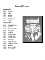
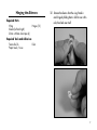
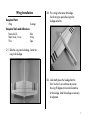
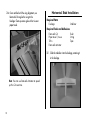
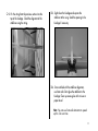
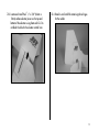
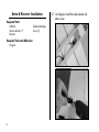
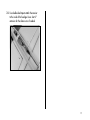
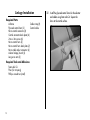
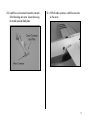
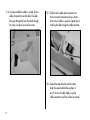
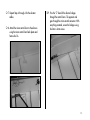
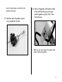
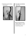
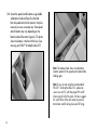
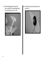
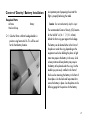
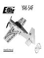
YAK-54F Assembly Manual 2 Table of Contents Introduction Introduction ................................................................2 Specifications .............................................................2 Contents of Kit/Parts Layout .........................................3 Optional Accessories ..................................................4 High Power Set-Up* ....................................................4 High Power Outrunner (direct drive) Set-Up* .................4 Indoor/Lightweight Outrunner (direct drive) Set-Up .........5 Warning ....................................................................5 Additional Tools and Adhesives ....................................5 Before Starting Assembly .............................................6 Using the Manual .......................................................6 Warranty Information ..................................................6 Hinging the Ailerons ...................................................7 Wing Installation ........................................................9 Horizontal Stab Installation ........................................10 Hinging the Elevator and Rudder ................................12 Servo & Receiver Installation ......................................14 Linkage Installation....................................................16 Motor & Speed Control Installation .............................20 Landing Gear Installation ...........................................25 Center of Gravity / Battery Installation ........................27 Control Throws .........................................................28 2005 Official AMA National Model Aircraft Safety Code .....................30 Thank you for purchasing the Quique Somenzini designed Yak 54F ARF Park Flyer, which is based on his popular gas-powered competitive Yak 54F aerobatic airplanes. Quique designed this model to compete at top-level competitions such as the eTOC and for nationwide demos. Quique uses his own unique A-frame design on the fuselage shape, which reduces flex in the more rigid fuselage giving you more precision control. From super slow to top airspeed, flying the Yak features a great combination of smoothness and precision, helping make this foam Yak-54F an extreme 3D flying performer like no other foam airplanes of this class. The Yak-54F will be capable of doing all the maneuvers that you have ever dreamt of and more. Specifications Wingspan: 37 in (940mm) Length: 37.5 in (950mm) Wing Area: 345 sq in (22.2 sq dm) Weight w/o Battery: 10–11 oz (280–310 g) Weight w/ Battery: 12–14 oz (340–400 g) Contents of Kit/Parts Layout Large Replacement Parts: EFL2126 Main Wing EFL2127 Fuselage EFL2128 Tail Assembly EFL2129 Wheel Pants EFL2130 Landing Gear Covers EFL2134 Landing Gear Small Replacement Parts: EFL2131 Plywood Tail Control Horns EFL2133 Aileron Rods EFL2135 Hook & Loop & Servo Tape EFLA200 Micro Control Horns EFLA202 Micro Tail Skid EFLA203 Micro Control Connectors EFLA204 Micro Rubber Spinner EFLA213 E-flite/JR/Horizon Decals EFLA214 Micro Pull-Pull Set EFLA220 Foam Park Wheels, 1.25” EFLM207 Pinion Gear, 10T 0.4 Module EFLM221 Gearbox, 6.6:1 EFLM222 Spur Gear, 66T w/Shaft EFLP1260 12 x 6 Slow Flyer Prop 3 Required Electronics & Accessories JRP6654** 6102FM, R610UL & 4-S241 Complete radio system JRPR610UL** R610UL 6CH FM Receiver, Shrinkwrap JRPS241 S241 Sub-Micro Servo (3) JRPA212 Large Arms w/Screws - need 2 package EFLA311 20-Amp Brushless ESC EFLC3005 Celectra 1-3 Cell Li-Po Charger EFLA208 Foam Safe CA / Activator EFLA250 Park Flyer Tool Assortment, 5 pc High Power Motor Set-Up* EFLM1000 EFLP1260 EFLB1016 or THP13203S Park 370 Brushless Motor, 4100 Kv 12 x 6 Slow Flyer Prop (2) - keep extras on hand 11.1V 1200mAh 3-Cell Li-Po, 16GA 1320mAh 3-Cell 11.1V Li-Po, 16GA * Use with included 12 x 6 prop, 6.6:1 gearbox, and 10T pinion. Proper throttle management is required when using high performance set-ups. 4 High Power Outrunner (direct drive) Motor Set-Up* EFLM1305 EFLP1047 or EFLP1147 EFLB1016 or THP13203S Park 400 Outrunner Motor, 920 Kv 10 x 4.7 Slow Flyer Prop (2) 11 x 4.7 Slow Flyer Prop (2) 11.1V 1200mAh 3-Cell Li-Po, 16GA 1320mAh 3-Cell 11.1V Li-Po, 16GA * Proper throttle management is required when using high performance set-ups. Indoor/Lightweight Outrunner (direct drive) Motor Set-Up EFLM1200 EFLP1047 EFLB1005 THP9003S Park 370 Outrunner Motor, 1080 Kv 10 x 4.7 Slow Flyer Prop (2) 11.1V 860mAh 3-Cell Li-Po, 16GA 900mAh 3-Cell 11.1V Li-Po, 16GA Additional Tools and Adhesives Tools Hobby knife Ruler Hot glue gun T-Pins Small Phillips Screwdriver (EFLA257 - included with EFLA250) Paper towel/tissue String Tape Pliers Hex Wrench: 3/32" (EFLA251 - included with EFLA250) Nut Driver: 5.5mm (EFLA255 - included with EFLA250) Warning An RC aircraft is not a toy! If misused, it can cause serious bodily harm and damage to property. Fly only in open areas, preferably at AMA (Academy of Model Aeronautics) approved flying sites, following all instructions included with your radio. Lithium Polymer batteries are significantly more volatile than alkaline or Ni-Cd/Ni-MH batteries used in RC applications. All manufacturer’s instructions and warnings must be followed closely. Mishandling of Li-Po batteries can result in fire. Adhesives Hot Glue 5 Before Starting Assembly Before beginning the assembly of your Yak-54F, remove each part from its bag for inspection. Closely inspect the fuselage, wing panels, rudder and stabilizer for damage. If you find any damaged or missing parts, contact the place of purchase. Using the Manual This manual is divided into sections to help make assembly easier to understand, and to provide breaks between each major section. Remember to take your time and follow the directions. Warranty Information Horizon Hobby, Inc. guarantees this kit to be free from defects in both material and workmanship at the date of purchase. This warranty does not cover any component parts damage by use or modification. In no case shall Horizon Hobby’s liability exceed the original cost of the purchased kit. Further, Horizon Hobby reserves the right to change or modify this warranty without notice. In that Horizon Hobby has no control over the final 6 assembly or material used for the final assembly, no liability shall be assumed nor accepted for any damage resulting from the use of the final assembled product. By the act of using the assembled product, the user accepts all resulting liability. Please note that once assembly of the model has been started, you must contact Horizon Hobby, Inc. directly regarding any warranty question. Please do not contact your local hobby shop regarding warranty issues, even if that is where you purchased it. This will enable Horizon to better answer your questions and service you in the event that you may need any assistance. If the buyer is not prepared to accept the liability associated with the use of this product, the buyer is advised to return this kit immediately in new and unused condition to the place of purchase. Horizon Hobby, Inc. 4105 Fieldstone Road Champaign, Illinois 61822 (877) 504-0233 horizonhobby.com Hinging the Ailerons Required Parts Wing Aileron (left and right) 20mm x 80mm clear tape (4) Hinges (10) 1. Remove the ailerons from the wing. Break in each hinge by folding them in half or over a thin ruler, then back over itself. Required Tools and Adhesives Foam-safe CA Ruler Paper towel / tissue 7 2. Install the hinges into the aileron. Slide the aileron hinges into the wing until there is a slight 1/64" gap between the wing and aileron. Apply foam-safe CA to each hinge, top and bottom. Do not use accelerator during this process, as the CA must soak into the hinge. Remove excess CA with a tissue or paper towel. 3. Locate the four 20mm x 80mm tape pieces. Place the tape on the top and bottom along the hinge line starting at the inside end (root) of the aileron continuing past the hole for the control horn. This will reinforce the aileron and help prevent stress on the control horn. Repeat this step for the other wing panel. 8 Wing Installation Required Parts Wing Fuselage 2. Pin a string to the center aft fuselage. Use the string to square the wing to the fuselage centerline. Required Tools and Adhesives Foam-safe CA Ruler Paper towel / tissue String T-Pins Tape 1. Slide the wing into the fuselage. Center the wing in the fuselage. 3. Look directly down the fuselage from the front. Use the fin as a reference to position the wing 90-degrees to the vertical centerline of the fuselage. Sand the fuselage as necessary for alignment. 9 4. Once satisfied with the wing alignment, use foam-safe CA to glue the wing to the fuselage. Clean up excess glue with a tissue or paper towel. Horizontal Stab Installation Required Parts Fuselage Stabilizer Required Tools and Adhesives Foam-safe CA Ruler Paper towel / tissue String T-Pins Tape Foam-safe activator 1. Slide the stabilizer into the fuselage, centering it in the fuselage. Note: You can use foam-safe Activator to speed up this CA cure time. 10 2. Pin the string from the previous section into the top of the fuselage. Check the alignment of the stabilizer using the string. 3. Sight down the fuselage and square the stabilizer to the wing. Sand the opening in the fuselage if necessary. 4. Once satisfied with the stabilizer alignment, use foam-safe CA to glue the stabilizer to the fuselage. Clean up excess glue with a tissue or paper towel. Note: You can use foam-safe Activator to speed up this CA cure time. 11 Hinging the Elevator and Rudder Required Parts Airframe Elevator (2) Rudder Hinge (7) Carbon fiber elevator joiner 2 5/8" x 3/8" (66 x 22 mm) (2) Required Tools and Adhesives Foam-safe CA Paper towel / tissue 2. Install the hinges into an elevator half. Slide the elevator hinges into the stabilizer until there is a slight 1/64" gap between the stabilizer and elevator. Make sure the elevator can move freely. Apply foam-safe CA to each hinge, top and bottom. Do not use accelerator during this process, as the CA must soak into the hinge. Remove excess CA with a tissue or paper towel. Repeat for both elevator halves. 1. Break in each of the four hinges by folding them in half or over a thin ruler, then back over itself. Note: The elevator half with the slot for the control horn goes on the left side of the fuselage. 12 3. Locate and install the 2 5/8" x 3/8" (66mm x 10mm) carbon elevator joiners on the top and bottom of the elevators using foam-safe CA. Do not block the hole for the elevator control horn. 4. Break in and install the remaining three hinges for the rudder. 13 Servo & Receiver Installation Required Parts Airframe Servo extension, 3" Receiver Required Tools and Adhesives Hot glue 14 1. Use hot glue to install the rudder, elevator and aileron servos. Double-sided tape Servo (3) 2. Use double-sided tape to attach the receiver to the inside of the fuselage. Use a short 3" extension for the aileron servo if needed. 15 Linkage Installation Required Parts Airframe Cable crimp (8) Plywood control horn (2) Control cable Micro control connector (6) Control connector back plate (6) 2mm x 3mm screw (6) Micro control horn (2) Micro control horn back plate (2) Micro cable adjust connector (4) Aileron linkage, 6-inch (2) Long servo arm (3) Required Tools and Adhesives Foam-safe CA Pliers (for crimping) Phillips screwdriver (small) 16 1. Install the plywood control horns for the elevator and rudder using foam-safe CA. Square the horns to the control surface. 2. Install the six micro control connectors into each of the three long servo arms. Secure them using the control connector back plates. 3. With the radio system on, install the servo arms on the servos. 17 4. Use tape to hold the rudder in neutral. Slide a cable crimp onto the control cable. The cable then goes through the horn, then back through the crimp. Use pliers to secure the crimp. 5. Silde the micro cable adjust connector into the micro control connector and use a 2mm x 3mm screw to hold it in position. Repeat Step 4, installing the cable through the cable connector. 6. Remove the tape from the control surface. Install the second cable following Steps 4 and 5. Tension the cables lightly using the cable connectors to pull the surface into neutral. 18 7. Repeat Steps 4 through 6 for the elevator cables. 8. Attach the micro control horn to the ailerons using the micro control horn back plates and foam-safe CA. 9. Pass the “Z” bend of the aileron linkages through the control horns. The opposite end goes through the micro control connector. With everything centered, secure the linkages using the 2mm x 3mm screws. 19 Motor & Speed Control Installation Required Parts Airframe 6.6:1 (66T spur) gearbox (if you are not installing an Outrunner motor) 10T pinion gear, 0.4 module x 6mm 12 x 6 prop (use 12 x 6 if you are using the gearbox with our recommended motor) 2.5mm x 10mm sheet metal screws (4) 3mm x 8mm screws/3mm washers (2) (use for mounting Outrunner motor) 50mm x 85mm fuselage doubler Brushless motor Brushless speed control 1/2" x 6 3/4" (13mm x 170mm) tape Required Tools and Adhesives Foam-safe CA Phillips screwdriver (small) Hex wrench, 3/32" Note: Steps 1 through 4 are for installing a gearbox and motor, while Steps 5 though 7 are for installing an Outrunner motor 20 1. It may be necessary to attach motor adapters or other accessories to your particular motor at this time. Note: Use the instructions provided with the motor to install any accessories. Follow the instructions provided with the gearbox for some helpful hints for installing the motor. When installing your motor into the E-flite™ gearbox, it is very important that the gear mesh is set correctly and is smooth with no binding. The E-flite gearbox features adjustable slotted mounting holes to ensure your gear mesh is correct. Remember if the gear mesh is too loose or too tight, it may strip the gears. To extend the life of your gearbox, we also recommend using a small amount of grease, such as lithium grease, on the spur gear. It is also very important to check to be sure the propeller is balanced before installing onto the shaft. An unbalanced propeller may strip the gears. When installing the propeller, please be sure not to over-tighten the 3mm lock nut. The use of the lock nut will prevent the propeller from coming loose. Use the 10-tooth pinion we include with this airplane on the motor. 2. Attach the motor to the gearbox using the 3. Make sure the gearbox sits flat against the back of the firewall by removing any excess glue. Attach the gearbox using the 2.5mm x 10mm sheet metal screws. screws provided with the motor. Hint: You may want to plug in the speed control before installing the gearbox. 21 4. Attach the propeller as shown. 5. To use the E-flite Outrunners, the shaft of the motor must exit the fixed part of the motor instead of through the rotating portion. You will have to change this. Loosen the setscrew in the rotating part of the motor. Slide the shaft though the motor and tighten the setscrew. Note: If you are using either the E-flite™ Park 370 Outrunner or Park 400 Outrunner, follow the next steps for changing the shaft and installation of this motor. 22 6. Mount the motor, using two 3mm x 8mm screws and two 3mm washers. 7. Attach the propeller using the propeller adapter included with the motor. Note: If using a direct drive Outrunner motor, a smaller prop is needed. Use 11 x 4.7 for the Park 400 Outrunner, 920 Kv or use a 10 x 4.7 for the Park 370 Outrunner, 1080 Kv. 23 8. Secure the speed control location using doublesided tape or hook and loop. Run the lead from the speed control to the receiver. It may be necessary to use a servo extension. Exact speed control location may vary depending on the brand used and the center of gravity. This photo shows the location in the front of the fuse if you are using our E-flite™ 20-Amp Brushless ESC. Note: The above photo shows an alternative location option for the speed control behind the landing gear. Note: If you are not using the recommended EFLA311 20-Amp Brushless ESC, please be sure to use an ESC with the proper 9V cutoff when using 3-Cell Li-Po packs. We also suggest this cutoff to be of the soft variety to prevent hard motor cutoffs during low level 3D flying. 24 Landing Gear Installation Required Parts Airframe Tail skid 1 ¼-inch wheel (2) Wheel retainer (2) Landing gear fairing (2) 2. Install the landing gear into position by pressing up into the landing gear mount. Landing gear Wheel pant (2) Required Tools and Adhesives Hot glue Foam-safe CA 1. Glue the tail skid using foam-safe CA Note: Use a small amount of foam-safe CA if the landing gear is loose in the slot. 25 3. Install the landing gear fairings and wheel pants using hot glue. We recommend gluing the wire to the fairings only at the two ends. 26 4. Install the wheels using the wheel retainers and foam-safe CA. Center of Gravity / Battery Installation Required Parts Airframe Hook and loop Battery 1. Glue the 50mm x 85mm fuselage doubler in position using foam-safe CA. This will be used for the front battery location. An important part of preparing the aircraft for flight is properly balancing the model. Caution: Do not inadvertently skip this step! The recommended Center of Gravity (CG) location for the Yak-54F is 3/8 – 1 3/4" (10 – 45mm) behind the front wing spar against the fuselage. The battery can be located either in the front of the plane or under the wing, depending on the equipment used when building the plane. A light motor may require the battery in the nose, while a heavy motor and heavy battery may require the battery to be placed under the wing. Use the doubler you previously installed in the front of the fuse when mounting the battery in the front of the airplane. Use the hook and loop material to secure the battery in place. See the photos on the following page for the positions for the battery. 27 Control Throws Aileron: 2" Up 2" Down Elevator: 2 1/4" Up 2 1/4" Down Rudder: 2 1/2" Right 2 1/2" Left Note: The above throws are a good starting point for high rates and most flight conditions. Experienced 3D pilots can use even higher throws for extreme maneuvers. 28 2005 Official AMA National Model Aircraft Safety Code GENERAL 1) I will not fly my model aircraft in sanctioned events, air shows or model flying demonstrations until it has been proven to be airworthy by having been previously, successfully flight tested. 2) I will not fly my model higher than approximately 400 feet within 3 miles of an airport without notifying the airport operator. I will give right-of-way and avoid flying in the proximity of full-scale aircraft. Where necessary, an observer shall be utilized to supervise flying to avoid having models fly in the proximity of full-scale aircraft. 3) Where established, I will abide by the safety rules for the flying site I use, and I will not willfully or deliberately fly my models in a careless, reckless and/ or dangerous manner. 4) The maximum takeoff weight of a model is 55 pounds, except models flown under Experimental Aircraft rules. 30 5) I will not fly my model unless it is identified with my name and address or AMA number on or in the model. (This does not apply to models while being flown indoors.) 6) I will not operate models with metal-bladed propellers or with gaseous boosts, in which gases other than air enter their internal combustion engine(s); nor will I operate models with extremely hazardous fuels such as those containing tetranitromethane or hydrazine. RADIO CONTROL 1) I will have completed a successful radio equipment ground range check before the first flight of a new or repaired model. 2) I will not fly my model aircraft in the presence of spectators until I become a qualified flier, unless assisted by an experienced helper. 3) At all flying sites a straight or curved line(s) must be established in front of which all flying takes place with the other side for spectators. Only personnel involved with flying the aircraft are allowed at or in front of the flight line. Intentional flying behind the flight line is prohibited. 4) I will operate my model using only radio control frequencies currently allowed by the Federal Communications Commission. (Only properly licensed Amateurs are authorized to operate equipment on Amateur Band frequencies.) 5) Flying sites separated by three miles or more are considered safe from site-to site interference, even when both sites use the same frequencies. Any circumstances under three miles separation require a frequency management arrangement, which may be either an allocation of specific frequencies for each site or testing to determine that freedom from interference exists. Allocation plans or interference test reports shall be signed by the parties involved and provided to AMA Headquarters. Documents of agreement and reports may exist between (1) two or more AMA Chartered Clubs, (2) AMA clubs and individual AMA members not associated with AMA Clubs, or (3) two or more individual AMA members. 6) For Combat, distance between combat engagement line and spectator line will be 500 feet per cubic inch of engine displacement. (Example: .40 engine = 200 feet.); electric motors will be based on equivalent combustion engine size. Additional safety requirements will be per the RC Combat section of the current Competition Regulations. 7) At air shows or model flying demonstrations, a single straight line must be established, one side of which is for flying, with the other side for spectators. 8) With the exception of events flown under AMA Competition rules, after launch, except for pilots or helpers being used, no powered model may be flown closer than 25 feet to any person. 9) Under no circumstances may a pilot or other person touch a powered model in flight. 31 © 2005 Horizon Hobby, Inc. 4105 Fieldstone Road Champaign, Illinois 61822 (877) 504-0233 horizonhobby.com 7567