1
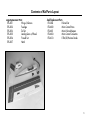
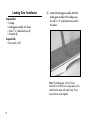
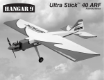
Mini Ultra Stick Assembly Manual Table of Contents 2 Introduction ................................................................2 Specifications .............................................................2 Contents of Kit/Parts Layout .........................................3 Required Radio Equipment ...........................................4 Important Information About Motor Selection .................5 Sport Setup ................................................................6 High Power Setup (Using Gearbox)* ............................6 Required Tools and Adhesives ......................................7 Optional Accessories ..................................................7 Using the Manual .......................................................7 Warning ....................................................................7 Before Starting Assembly .............................................8 Note on Lithium Polymer Batteries .................................8 Warranty Information ..................................................9 Landing Gear Installation ...........................................10 Firewall Installation ...................................................11 Outrunner Motor Installation.......................................13 Inrunner Motor Installation .........................................16 Tail Installation..........................................................21 Wing Preparation .....................................................22 Quad Flap Modification (Optional) .............................25 Radio Installation ......................................................26 Final Assembly .........................................................29 Range Testing the Radio ............................................31 Control Throws .........................................................32 Center of Gravity ......................................................32 Preflight ...................................................................33 2005 Official AMA National Model Aircraft Safety Code ........34 Introduction Thank you for purchasing the E-flite™ Mini Ultra Stick ARF. The Mini Ultra Stick is an electric park flyer version of the popular Hangar 9® Ultra Stick™ series and has similar flight characteristics as the larger version. It is ideal for those transitioning into aerobatic park flyers who do not want a higher performance 3D airplane. We include two firewall options for you to decide if you want to install a brushless outrunner motor or an inrunner motor. Specifications Wingspan: Length: Wing Area: Weight w/o Battery: Weight w/ Battery: 38.75 in (985mm) 34 in (865mm) 325 sq in (21 sq dm) 19–20 oz (540–565 g) 22–25 oz (625–710 g) Contents of Kit/Parts Layout Large Replacement Parts: EFL2251 Wing w/Ailerons EFL2252 Fuselage EFL2253 Tail Set EFL2255 Landing Gear w/Wheels EFL2256 Firewall Set EFL2257 Hatch Small Replacement Parts EFL2254 Pushrod Set EFLA200 Micro Control Horns EFLA201 Micro Pushrod Keepers EFLA203 Micro Control Connectors EFLA213 E-flite/JR/Horizon Decals 3 Required Radio Equipment You will need a minimum 4-channel transmitter, crystals, micro receiver, and four sub-micro servos. You can choose to purchase a complete radio system that includes all of these items or, if you are using an existing transmitter, just purchase the other required equipment separately. JSP30610 JSP30615 6-Channel UltraLite Rx w/o Crystal, Negative Shift Fut/HRC (72 MHz) You may wish to install the optional quad flaps, in which case you will need a 7-channel radio and receiver on 72 MHz with mixing and six sub-micro servos. JRPXFR** FM Receiver Crystal EFLRS75 7.5 Gram Sub-Micro Servo (4) JSP98020 Y-Harness, Standard 6" JSP98100 Servo Extension, 3" The Spektrum radio system listed below will not work for the quad flap option. Complete Radio System SPM2460 DX6 DSM 6CH Park Flyer w/4-S75 Note: We recommend the crystal-free, interference-free Spektrum DX6 2.4GHz DSM 6-channel System, which includes a micro receiver and 4 sub-micro servos. 4 Or Purchase Separately 6-Channel UltraLite Rx w/o Crystal, Positive Shift JR/Air (72 MHz) Or Optional Quad Flaps EFLRS75 7.5 Gram Sub-Micro Servo (6) JSP98100 Servo Extension, 3" (6) JSP98030 Servo Extension, 12" (2) JRPR700 R700 7CH Slimline FM Rx Important Information About Motor Selection The Mini Ultra Stick does not include a gearbox or propeller. However, we do include two different firewalls for attaching to the nose of the plane. You need to first determine what power system you will be using, an inrunner with a gearbox, or an outrunner. We even include a firewall stick mount, which attaches to the Stick Mount Firewall. The Outrunner Firewall can accommodate small and larger outrunners, with options of mounting your outrunner on the outside with your aluminum mount or inside of the nose directly to the firewall. We are recommending the Park 450 Brushless Outrunner Motor, 890Kv (EFLM1400) with a 10x7 propeller (EFLP1070). This will provide you with excellent aerobatic power for sport pilots and a worry-free Outrunner motor. For a geared alternative, try the Park 400 Brushless Inrunner Motor, 4200Kv (EFLM1100) with a 6.5:1 gearbox (new HD EFLM240), 11x7 propeller (EFLP1170), and a 2100mAh 3-cell Li-Po battery. This setup will provide more power for extreme flights. It is very important to monitor gearbox wear and motor temperature when using the 4200Kv motor. Lack of proper throttle management using this motor and a 3-cell Li-Po battery may result in damage to the motor, gearbox, ESC, and battery. Adequate motor cooling is also very important, so make sure the motor is cooled properly in the cowl. 5 Sport Setup High Power Setup (Using Gearbox)* EFLM1400 Park 450 Brushless Outrunner Motor, 890Kv EFLM1100 Park 400 Brushless Inrunner Motor, 4200Kv EFLA311B 20-Amp Brushless ESC (V2) EFLM240 EFLP1070 10 x 7 Slow Flyer Prop (2) 400 Gearbox, 6.5:1 0.5 Module w/2 Pinions THP21003SPL or EFLB1035 2100mAh 3-Cell 11.1V Li-Po, 16GA EFLA311B 20-Amp Brushless ESC (V2) 11.1V 2100mAh 3-Cell Li-Po, 16GA EFLP1170 11 x 7 Slow Flyer Prop WSD1300 Ultra Plug, Male/Female Set Spinner, 1-3/4” Red (optional) EFLC3005 Celectra™ 1–3 Cell Li-Po Charger EFLA270 or EFLA204 This is a sport flyer setup for smooth and stable flights. Micro Rubber Spinner (optional) THP21003SPL or EFLB1035 2100mAh 3-Cell 11.1V Li-Po, 16GA WSD1300 Ultra Plug, Male/Female Set EFLC3005 Celectra 1-3 Cell Li-Po Charger 11.1V 2100mAh 3-Cell Li-Po, 16GA Proper throttle management is required when using high performance setups. Using this setup with 3 cells will give you plenty of power for zippy flights. 6 Required Tools and Adhesives Tools & Equipment EFLA250 Park Flyer Tool Assortment, 5-piece Or Purchase Separately EFLA257 Screwdriver, #0 Phillips (or included with EFLA250) EFLA255 Nut Driver, 5.5mm (or included with EFLA250) EFLA251 Hex Wrench: 3/32" (or included with EFLA250) Threadlock EFLA110 EFLA212 Power Meter Gear Puller: 1mm–5mm Shaft Using the Manual This manual is divided into sections to help make assembly easier to understand, and to provide breaks between each major section. Remember to take your time and follow the directions. Warning Hobby knife Square Ruler Felt-tipped pen String Adhesives Medium CA Thick CA HAN8000 Optional Accessories An RC aircraft is not a toy! If misused, it can cause serious bodily harm and damage to property. Fly only in open areas, preferably at AMA (Academy of Model Aeronautics) approved flying sites, following all instructions included with your radio. 6-Minute Epoxy (option for attaching firewall) (for mounting motor to gearbox) Keep loose items that can get entangled in the propeller away from the prop, including loose clothing, or other objects such as pencils and screwdrivers. Especially keep your hands away from the propeller. 7 Before Starting Assembly Before beginning the assembly of your Mini Ultra Stick, remove each part from its bag for inspection. Closely inspect the fuselage, wing panels, rudder and stabilizer for damage. If you find any damaged or missing parts, contact the place of purchase. 8 Note on Lithium Polymer Batteries Lithium Polymer batteries are significantly more volatile than alkaline or Ni-Cd/ Ni-MH batteries used in RC applications. All manufacturer’s instructions and warnings must be followed closely. Mishandling of Li-Po batteries can result in fire. Always follow the manufacturer’s instructions when disposing of Lithium Polymer batteries. Warranty Information Horizon Hobby, Inc. guarantees this kit to be free from defects in both material and workmanship at the date of purchase. This warranty does not cover any parts damaged by use or modification. In no case shall Horizon Hobby’s liability exceed the original cost of the purchased kit. Further, Horizon Hobby reserves the right to change or modify this warranty without notice. Once assembly of the model has been started, you must contact Horizon Hobby, Inc. directly regarding any warranty question that you have. Please do not contact your local hobby store regarding warranty issues, even if that is where you purchased it. This will enable Horizon to better answer your questions and provide service in the event that you may need any assistance. In that Horizon Hobby has no control over the final assembly or material used for the final assembly, no liability shall be assumed nor accepted for any damage of or caused by the final user-assembled product. By the act of using the product, the user accepts all resulting liability. If the buyer or user is not prepared to accept the liability associated with the use of this product, they are advised to return this kit immediately in new and unused condition to the place of purchase. For any additional questions please contact: Horizon Hobby Product Support 4105 Fieldstone Road Champaign, Illinois 61822 (877) 504-0233 www.horizonhobby.com 9 Landing Gear Installation Required Parts • Fuselage • Landing gear assembly with wheels • 4-40 x 1/2" socket head screw (2) • #4 washer (2) 1. Locate the landing gear assembly. Attach the landing gear assembly to the fuselage using two 4-40 x 1/2" socket head screws and two #4 washers. Required Tools • Hex wrench: 3/32" Note: The landing gear will only fit one direction for the holes to line up properly. Also, check that the wheel will rotate freely. If not, loosen the nuts and retighten. 10 Firewall Installation Required Parts • Outrunner firewall or Stick Mount firewall • 4-40 blind nut (4) Choose the firewall that fits best with the motor you have selected to use. Install the 4-40 blind nuts to the firewall as shown. This will be the back-side of the firewall. Required Tools and Adhesives • 6-minute epoxy or • Thick CA 1. The Mini Ultra Stick does not include a gearbox or propeller. However, we do include two different firewalls for attaching to the nose of the plane. You need to first determine what power system you will be using, an inrunner with a gearbox, or an outrunner. We even include a firewall stick mount, which attaches to the Stick Mount firewall. The Outrunner firewall can accommodate small and larger outrunners, with options for mounting your outrunner on the outside of the aircraft with your aluminum mount or inside of the nose directly to the firewall. Note: White UltraCote® is on the front side (outside) of the firewall and the blind nuts should be inserted on the inside of the firewall. 11 2. Attach the firewall to the sub-firewall structure on the front of the fuselage nose at this time using 6minute epoxy or thick CA. Note: Make sure to install the firewall as shown for the correct orientation. 12 Outrunner Motor Installation Option 1: Motor Installation Inside Fuselage Required Parts • Fuselage • Brushless motor • Brushless speed control • 4-40 x 1/4" socket head screw (4) • Prop adapter • Propeller Required Tools and Adhesives • Hex wrench: 3/32" Skip to page 16 for setup of an inrunner motor with gearbox. Note: This section covers the installation of a brushless outrunner motor with attachment to the outside. You do have the option of installing your outrunner inside the fuselage as well. If using our recommended E-flite™ Outrunner, it may be necessary to reverse the direction of your shaft to install the motor inside the fuse. See photo below for reference. 1. Install the outrunner motor using the hardware provided with the motor. The screws go through the front of the firewall and into the motor. 13 Option 2: Motor Installation Outside Fuselage 1. It may be necessary to attach motor mount 2. Attach the Outrunner motor to the front of the firewall using four 4-40 x 1/4" socket head screws. or other accessories to your particular motor at this time. Note: The mount is attached to the front (white side) of the firewall. Important Information About Your Brushless ESC Make sure your ESC brake is programmed to Off. Also, be sure to use an ESC with the proper 9V cutoff when using 3-cell Li-Po packs, or 6V cutoff when using 2-cell Li-Po packs. 14 3. Connect the ESC to the motor and secure it to the inside of the fuselage using hook and loop material. Actual ESC location may vary. 4. Slide the propeller adapter onto the motor. Place the propeller onto the adapter, then a spinner cone onto the adapter and secure. Note: It is very important that you check to be sure the propeller is balanced before installing onto the shaft. An unbalanced propeller will cause performance issues. E-flite™ propellers will need the center hole drilled out to fit the shaft size of your outrunner. It is very important the hole is drilled concentric. 15 Inrunner Motor Installation Required Parts • Fuselage • Brushless motor • Brushless speed control • #2 x 8mm screw (3) • 4-40 x 3/8" socket head screw (4) • EFLM1916 Firewall Stick Mount (included) • EFLM1900 Pinion Gear, 10T 0.4 Module 6mm w/2mm ID (included with E-flite™ motor) • EFLM240 400 Gearbox, 6.5:1 0.5 Module w/ 2 Pinions (required to purchase) • EFLP1170 11x7 Slow Flyer Propeller • EFLA 270 Spinner, 1 3/4" Red (optional) or • EFLA204 Micro Rubber Spinner (optional) Required Tools and Adhesives • Hex wrench: 3/32" • Nut driver: 5.5mm • Screwdriver, #0 Phillips • Medium CA • Threadlock 16 Note: This section covers the installation of an inrunner motor and gearbox. Refer back to Page 13 for outrunner installation. 1. It may be necessary to attach motor adapters or other accessories to your particular motor at this time. Note: Use the instructions provided with the motor to install any accessories. Follow the instructions provided with the gearbox for some helpful hints for installing the motor. When installing your motor into the E-flite gearbox, it is very important that the gear mesh is set correctly and is smooth with no binding. The E-flite gearbox features adjustable slotted mounting holes to ensure your gear mesh is correct. Remember, if the gear mesh is too loose or too tight it may strip the gears. To extend the life of your gearbox, we also recommend using a small amount of grease, such as lithium grease, on the spur gear. It is also very important to check to be sure the propeller is balanced before installing onto the shaft. An unbalanced propeller may strip the gears. When installing the propeller, please be sure not to over-tighten the 3mm locknut. The use of the locknut will prevent the propeller from coming loose. 3. Attach the firewall stick mount to the inrunner firewall using four 4-40 x 3/8" socket head screws. 2. Attach the motor to the gearbox using the screws provided with the motor and blue threadlock. Hint: The gearbox is in two pieces. Apply a bead of medium CA where the two pieces join to stiffen the mount for extreme aerobatics. 17 4. Slide the gearbox into position on the motor mount. Use a 1/16" drill to drill a hole on each side of the gearbox and into the mount. Stagger the holes so the screws will not interfere with each other. Secure the gearbox using three #2 x 8mm screws. Important Information About Your Brushless ESC Make sure your ESC brake is programmed to Off. Also, be sure to use an ESC with the proper 9V cutoff when using 3-Cell Li-Po packs, or 6V cutoff when using 2-cell Li-Po packs. 18 5. Connect the ESC to the motor and secure the ESC to the inside of the fuselage using hook and loop material. Actual ESC location may vary. 6. Slide the propeller onto the gearbox shaft. If 3 using our E-flite™ 1 /4" spinner, next slide on a spinner backplate spacer. If you are using a rubber spinner, you will slide it on after the propeller has been secured. Note: Two spacers have been provided that are placed between the propeller and spinner backplate. Use the thin spacer for low-pitch propellers, the thick spacer for high-pitch propellers. This will prevent the blades of the propeller from contacting the spinner backplate. 7. Slide the spinner backplate onto the gearbox shaft. Secure the propeller and spinner backplate using the supplied 3mm washer and 3mm locknut. Make sure not to over-tighten the 3mm locknut. Note: It is very important that you check to be sure the propeller is balanced before installing onto the shaft. An unbalanced propeller may strip the gear. When installing the propeller, please do not over-tighten the 3mm locknut. The use of the locknut will prevent the propeller from coming loose. 19 8. Snap the spinner cone onto the spinner backplate. 20 Tail Installation Required Parts • Fuselage • Rudder/Fin • Stabilizer/Elevator • 3mm locknut (2) • 3mm washer (2) 2. Attach the stabilizer using two 3mm washers and two 3mm locknuts. Do not tighten the locknuts all the way until after the wing is installed and you check the alignment. 1. Slide the rudder into position on the fuselage. The threaded rods extend through the bottom of the fuselage. Note: The tail section is removable for easy transporting if needed. When re-attaching, always check your alignment before flight to make sure the tail is square with the wing before tightening the locknuts completely. See instructions on page 31. 21 Wing Preparation Required Parts • Fuselage • Wing • Control horn (2) • 6-channel receiver • Servo w/hardware (2) • 6" Y-harness • Servo extension, 3" • 4-40 x 3/4" socket head screw (2) • 3mm washer (2) • Micro control connector (2) • 2mm x 4mm screw (2) • Micro control connector backplate (2) • 5" pushrod wire (2) Required Tools and Adhesives • Thin CA • Medium CA • Ruler • Drill • Drill bit: 3/32" • Screwdriver, #0 Phillips Note: For the optional Quad Flap modification, please refer to information on Page 25. 22 1. Install the aileron servo into the wing. The servo lead will exit the hole in the bottom center of the wing. Attach one side of a 6" Y-harness to the servo lead. We suggest you then hook up the Y-harness to a 3" servo extension. The 3" servo extension can remain permanently connected to your receiver so you do not have to unplug wires from your receiver each time you disconnect and remove the wing. 2. Secure the servo using the hardware that was provided with the servo. 3. Drill a 3/32" hole in the outside hole of a servo arm. Install a micro control connector in the hole, and then secure its location using a micro control connector backplate. 23 4. Attach the 5" pushrod wire to the control horn using the pre-formed “Z” bend in the wire. 5. Plug the aileron servo into the receiver and turn on the radio. Center the aileron servo electronically. Pass the wire through the micro control connector. Install the servo horn parallel to the aileron hinge line. Center the aileron, then secure the wire using the 2mm x 4mm screw. 6. Repeat Steps 2 through 5 for the remaining aileron linkage installation. 24 Quad Flap Modification (Optional) Optional Parts (for quad flaps) • Servo w/hardware (2 additional needed) • Servo extension, 12" (2) • Servos extension, 3" (6) • 7-channel receiver • 7-channel or greater transmitter • Micro control connector (2 additional) • 2mm x 4mm screw (2 additional) • Micro control connector backplate (2 additional) • 5" pushrod wire (2 additional) • Control horn (2 additional) This will mean you should use two 12” servo extensions to connect the two outer servos. You will also need two 3" extensions to connect the two inner servos. We suggest you use four additional 3" servo extensions that will connect each servo to the receiver. This way, depending on the receiver location, you will not have to disconnect wires directly from the receiver each time you remove the wing. Required Tools and Adhesives • Hobby knife • Covering iron • Thin CA The Mini Ultra Stick wing is designed with optional quadflaps. The ailerons have been designed with the option of cutting in half using a hobby knife. White covering has been supplied to cover the cut ends. Installing the servos is similar to that of the aileron instructions above. There are some additional changes. First, you will need at least a 7-channel or greater transmitter and receiver with servo reversing capability. Each servo should be connected separately to the 7-channel receiver. Note: See our Mini Ultra Stick website page for radio tips for quad flap operation using this setup. There are also options listed if you use a 6-channel transmitter and receiver. However, this method will require the purchase of a reversed servo and the use of a Y-harness to connect your two inner location servos. 25 Radio Installation Required Parts • Fuselage • Receiver • Servo w/hardware (2) • Micro control connector (2) • Control connector backplate (2) • 2mm x 4mm screw (2) • Hook and loop material • Micro pushrod keeper (2) Required Tools and Adhesives • Screwdriver, #0 Phillips • Drill • Drill bit: 3/64" 26 1. Install the rudder and elevator servos into the fuselage using the hardware provided with the servos. 2. Plug in the servos and ESC into the receiver. Mount the receiver to the side of the fuselage using hook and loop material. Route the antenna wire through the bottom of the fuselage to the rear. 3. Install the pushrod into the elevator control horn. Secure the pushrod wire using a micro pushrod wire keeper. Note: Do not cut the antenna wire, as this will reduce the range of your radio system. 27 4. Drill a 3/64" hole in the outside hole of a servo arm. Install a micro control connector in the hole, and then secure its location using a micro control connector backplate. 5. With the radio on, center the servo first. Then slide the control connector onto the wire and install the elevator servo arm onto the servo and secure with servo screw. Physically center the elevator so it is in line with the stabilizer. Use a 2mm x 4mm screw in the micro control connector to secure the pushrod wire. 6. Repeat Steps 3 through 5 for the rudder pushrod wire. 28 Final Assembly Required Parts • Fuselage • Wing • Battery • Battery hatch • 4-40 x 3/4" socket head bolt (2) • #4 washer (2) • Hook and loop tape • Hook and loop strap 1. With the aircraft fully assembled, install the battery into the battery compartment. Secure the battery using the hook and loop tape and a hook and loop strap. Required Tools and Adhesives • Hex wrench: 3/32" Note: Place a piece of hook and loop tape on the bottom of the battery and on the fuselage where the battery rests. This will keep the battery from shifting forward or backward during extreme maneuvers. 29 2. Install the battery hatch to the top of the fuselage. The magnet will hold the battery hatch in place. 30 3. Plug in the aileron (and flap) servo leads. Slide the wing dowels into the holes at the front. Use the two 4-40 x 3/4" socket head screws and two #4 washers to secure the wing. 4 Check your alignment of the wing to the horizontal stabilizer at this time. You should have some play in the stab holes. Measure the stab tip to the wing tip. Adjust the stab until the measurements are equal. Now you can tighten the 3mm locknuts at the stabilizer. Range Testing the Radio 1. Before each flying session, be sure to range check your radio. This is accomplished by turning on your transmitter with the antenna collapsed. Turn on the receiver in your airplane. With your airplane on the ground and the engine running, you should be able to walk 30 paces (approximately 100 feet) away from your airplane and still have complete control of all functions. If not, don’t attempt to fly! Have your radio equipment checked out by the manufacturer. 2. Double-check that all controls (aileron, elevator, rudder and throttle) move in the correct direction. 3. Be sure that your transmitter batteries are fully charged, per the instructions included with your radio. 31 Control Throws 1. Turn on the transmitter and receiver of your Mini Ultra Stick. Check the movement of the rudder, elevator and ailerons using the transmitter. Reverse the direction of the servos at the transmitter if necessary. 2. Use a ruler to adjust the throw of the elevator, ailerons and rudder. Adjust the position of the pushrod at the control horn to achieve the following measurements when moving the sticks to their endpoints. Measurements are taken at the widest point on the surface. Low Rate Ailerons: Up/Down 1 /2" (15mm) High Rate 5/8" (19mm) Elevator: Up/Down 9/16" (18mm) 7/8" (23mm) Rudder: Right/Left 7/8" (23mm) 1 1/4" (32mm) These are general guidelines measured from our own flight tests. You can experiment with higher rates to match your preferred style of flying. Center of Gravity Caution: Do not inadvertently skip this step! The recommended Center of Gravity (CG) location for the Mini Ultra Stick is 2 1/2" (63mm) behind the leading edge of the upper wing against the fuselage. After the first flights the throws can be adjusted for your personal preference. 32 Preflight Check Your Radio Before going to the field, be sure that your batteries are fully charged, per the instructions included with your radio. Charge both the transmitter and receiver pack for your airplane. Use the recommended charger supplied with your particular radio system, following the instructions provided with the radio. In most cases the radio should be charged the night before going out flying. Before each flying session, be sure to range check your radio. See your radio manual for the recommended range and instructions for your radio system. Each radio manufacturer specifies different procedures for their radio systems. Next, start the motor. With the model securely anchored, check the range again. The range test should not be significantly affected. If it is, don’t attempt to fly! Have your radio equipment checked out by the manufacturer. Note: Keep loose items that can get entangled in the propeller away from the prop. These include loose clothing, or other objects such as pencils and screwdrivers. Especially keep your hands away from the propeller. Double-check that all controls (aileron, elevator, rudder and throttle) move in the correct direction. Check the radio installation and make sure all the control surfaces are moving correctly (i.e. the correct direction and with the recommended throws). Test run the motor and make sure it transitions smoothly from off to full throttle and back. Also ensure the engine is installed according to the manufacturer’s instructions, and it will operate consistently. Check all the control horns, servo horns, and clevises to make sure they are secure and in good condition. Replace any items that would be considered questionable. Failure of any of these components in flight would mean the loss of your aircraft. 33 2005 Official AMA National Model Aircraft Safety Code GENERAL 1) I will not fly my model aircraft in sanctioned events, air shows or model flying demonstrations until it has been proven to be airworthy by having been previously, successfully flight tested. 2) I will not fly my model higher than approximately 400 feet within 3 miles of an airport without notifying the airport operator. I will give right-of-way and avoid flying in the proximity of full-scale aircraft. Where necessary, an observer shall be utilized to supervise flying to avoid having models fly in the proximity of full-scale aircraft. 3) Where established, I will abide by the safety rules for the flying site I use, and I will not willfully or deliberately fly my models in a careless, reckless and/ or dangerous manner. 4) The maximum takeoff weight of a model is 55 pounds, except models flown under Experimental Aircraft rules. 34 5) I will not fly my model unless it is identified with my name and address or AMA number on or in the model. (This does not apply to models while being flown indoors.) 6) I will not operate models with metal-bladed propellers or with gaseous boosts, in which gases other than air enter their internal combustion engine(s); nor will I operate models with extremely hazardous fuels such as those containing tetranitromethane or hydrazine. RADIO CONTROL 1) I will have completed a successful radio equipment ground range check before the first flight of a new or repaired model. 2) I will not fly my model aircraft in the presence of spectators until I become a qualified flier, unless assisted by an experienced helper. 2005 Official AMA National Model Aircraft Safety Code 3) At all flying sites a straight or curved line(s) must be established in front of which all flying takes place with the other side for spectators. Only personnel involved with flying the aircraft are allowed at or in front of the flight line. Intentional flying behind the flight line is prohibited. 4) I will operate my model using only radio control frequencies currently allowed by the Federal Communications Commission. (Only properly licensed Amateurs are authorized to operate equipment on Amateur Band frequencies.) 5) Flying sites separated by three miles or more are considered safe from site-to-site interference, even when both sites use the same frequencies. Any circumstances under three miles separation require a frequency management arrangement, which may be either an allocation of specific frequencies for each site or testing to determine that freedom from interference exists. Allocation plans or interference test reports shall be signed by the parties involved and provided to AMA Headquarters. Documents of agreement and reports may exist between (1) two or more AMA Chartered Clubs, (2) AMA clubs and individual AMA members not associated with AMA Clubs, or (3) two or more individual AMA members. 6) For Combat, distance between combat engagement line and spectator line will be 500 feet per cubic inch of engine displacement. (Example: .40 engine = 200 feet.); electric motors will be based on equivalent combustion engine size. Additional safety requirements will be per the RC Combat section of the current Competition Regulations. 7) At air shows or model flying demonstrations, a single straight line must be established, one side of which is for flying, with the other side for spectators. 8) With the exception of events flown under AMA Competition rules, after launch, except for pilots or helpers being used, no powered model may be flown closer than 25 feet to any person. 9) Under no circumstances may a pilot or other person touch a powered model in flight. 35 © 2005 Horizon Hobby, Inc. 4105 Fieldstone Road Champaign, Illinois 61822 (877) 504-0233 horizonhobby.com E-fliteRC.com 8200