1
Technical Reference
Hardware
Version 10.03 - March 2010
Studio Production Server
XS Series DISK RECORDER - Version 10.03 - Hardware Technical Reference Manual
EVS Broadcast Equipment SA – March 2010
Issue
10.03.B
C OPYRIGHT
EVS Broadcast Equipment – Copyright © 2009-2010. All rights reserved.
D ISCLAIMER
The information in this manual is furnished for inform ational use only and subject
to change without notice. While every effort has been made to ensure that the
information contained in this user manual is accurate, up-to-date and reliable,
EVS Broadcast Equipment cannot be held responsible for inaccuracies or errors
that may appear in this publication.
I MPROVEMENT R EQUESTS
Your comments will help us improve the quality of the user documentation. Do not
hesitate to send improvement requests, or report any error or inaccuracy on this
user manual by e-mail to [email protected].
i
Issue
10.03.B
ii
XS Series DISK RECORDER – Version 10.03 - Hardware Technical Reference
EVS Broadcast Equipment SA – March 2010
XS Series DISK RECORDER - Version 10.03 - Hardware Technical Reference Manual
EVS Broadcast Equipment SA – March 2010
Issue
10.03.B
Table of Contents
TABLE OF CONTENTS ................................................................................................... III WHAT’S NEW? ................................................................................................................ VI 1. OVERVIEW ............................................................................................................... 1 1.1 XS HIGH-RESOLUTION SERVER ..............................................................................................1 1.2 UNPACKING ................................................................................................................................2 1.3 DIMENSIONS ..............................................................................................................................2 1.3.1 Video Disk Recorder Main Frame 19 Inches ...........................................................................2 1.3.2 XT-HDX...................................................................................................................................3 1.3.3 SAS-HDX ................................................................................................................................4 1.4 INSTALLATION............................................................................................................................5 1.5 SAFETY, COMPLIANCE AND OPERATING CONDITIONS ........................................................5 1.5.1 Safety ......................................................................................................................................5 1.5.2 EMC Standards .......................................................................................................................5 1.5.3 EMC Warning ..........................................................................................................................6 1.5.4 CE Marking .............................................................................................................................7 1.5.5 Power Supply ..........................................................................................................................7 Environmental conditions ........................................................................................................................................... 8 Hot Swap Secondary Power Supply .......................................................................................................................... 8 Grounding .................................................................................................................................................................. 8 1.6 VENTILATION & RACK MOUNTING ...........................................................................................8 1.7 XS SERVER MAIN SPECIFICATIONS ........................................................................................9 1.7.1 Video .......................................................................................................................................9 1.7.2 Audio .......................................................................................................................................9 1.7.3 Video Codecs & Bitrates .......................................................................................................10 1.7.4 Recording Capacity for XS Servers.......................................................................................11 SCSI Disks ............................................................................................................................................................... 11 SAS Disks ................................................................................................................................................................ 12 1.7.5 Supported SMPTE Standards ...............................................................................................17 1.7.6 Maximum Bitrate values ........................................................................................................17 1.7.7 AVID DNxHD ® and APPLE ProRes 422..............................................................................18 Introduction .............................................................................................................................................................. 18 Video Bitrate Compatibility with Avid and Apple Products ....................................................................................... 18 Choices of Bitrates when using Avid DNxHD® or Apple ProRes 422 with EVS XS servers ................................... 19 1.7.8 Raid level: 3 ..........................................................................................................................22 1.7.9 Interpolation ..........................................................................................................................23 2-line Interpolator ..................................................................................................................................................... 23 4-line Interpolator ..................................................................................................................................................... 23 2. CABLING ................................................................................................................ 25 2.1 XS REAR PANEL .......................................................................................................................25 2.1.1 Open Configuration ...............................................................................................................25 (XS 5U-444 Config) Shown with Optional AES on BNC Connector Option ............................................................. 25 (XS 5U-444 Config) Shown with Optional AES on Multi-pin Connector Option ....................................................... 26 (XS 5U-222 Config) Shown with Optional AES on BNC Connector Option ............................................................. 26 (XS 5U-222 Config) Shown with Optional AES on Multi-pin Connector Option ....................................................... 27 2.1.2 Ingest Configuration (XS 5U-441 Config) ..............................................................................27 Shown with Optional AES on BNC Connector Option ............................................................................................. 27 Shown with Optional AES on Multi-pin Connector Option ....................................................................................... 28 2.1.3 Playout Configuration (XS 5U-414 Config) ............................................................................28 Shown with Optional AES on BNC Connector Option ............................................................................................. 28 iii
Issue
10.03.B
XS Series DISK RECORDER – Version 10.03 - Hardware Technical Reference
EVS Broadcast Equipment SA – March 2010
Shown with Optional AES on Multi-pin Connector Option ....................................................................................... 29 2.2 GPI IN CONNECTIONS .............................................................................................................29 2.2.1 Relay Æ Opto inputs on the XS server (GPI inputs 1, 2, 3, 4) ..............................................29 2.2.2 Relay Æ TTL inputs on the XS Server (GPI inputs 5, 6, 7, 8)...............................................30 2.2.3 TTL Æ TTL inputs on the XS server (GPI input 5, 6, 7, 8) ....................................................30 2.3 GPI OUT SETTINGS .................................................................................................................31 2.4 MTPC GPIO CONNECTOR 15/10/02 ........................................................................................31 2.4.1 GPIO Connector: SUB-D 25-pins Male .................................................................................31 2.4.2 GPIO hardware specifications ...............................................................................................32 2.5 RS422 CONNECTOR ................................................................................................................33 2.6 AUDIO CONFIGURATIONS ......................................................................................................33 2.6.1 CODA FOR XS .....................................................................................................................33 2.6.2 PIN ASSIGNMENT ON SUB-DB15 CONNECTORS ............................................................34 2.7 CONNECTING MULTIPLE EVS VIDEO SERVERS ON XNET .................................................36 2.7.1 Connection diagram without EVS XNet HUB ........................................................................36 2.7.2 Connection Diagram With EVS XHub[2] XNet HUB ..............................................................37 2.7.3 Required Conditions to Set up and run XNet ........................................................................38 2.7.4 Starting XNet .........................................................................................................................39 2.7.5 XNet Performances & Troubleshooting .................................................................................40 2.8 GIGABIT NETWORK .................................................................................................................41 2.8.1 Functional Overview..............................................................................................................41 2.8.2 Backup of Clips .....................................................................................................................42 2.8.3 Restore of Clips ....................................................................................................................43 2.8.4 Switches................................................................................................................................44 2.9 3. Supported Switches ................................................................................................................................................. 44 Comparison .............................................................................................................................................................. 44 Additional information............................................................................................................................................... 45 REDUNDANT IPDP SERIAL LINK .............................................................................................46 HARDWARE DESCRIPTION ................................................................................. 47 3.1 BOARDS AND SLOT CONFIGURATIONS ................................................................................47 3.2 VIDEO AND REFERENCE BOARDS ........................................................................................47 3.2.1 XS COHX Board ...................................................................................................................47 3.3 Jumpers on the COHX base module ....................................................................................................................... 48 Leds on the COHX base module with genlock ........................................................................................................ 49 Leds on the COD A and COD B modules (from left to right) ................................................................................... 49 Connectors on the COD A and COD B modules ..................................................................................................... 50 Channel Assignment ................................................................................................................................................ 53 XS AUDIO CODEC BOARD ......................................................................................................54 LED information and connector................................................................................................................................ 54 3.4 RAID CONTROLLER BOARDS .................................................................................................55 3.4.1 HCTX board ..........................................................................................................................55 Jumpers ................................................................................................................................................................... 56 LEDs ........................................................................................................................................................................ 56 Connectors ............................................................................................................................................................... 57 Gigabit Connectors .................................................................................................................................................. 57 3.4.2 RCTL Board on Disk Array (with HCTX) ...............................................................................58 SCSI Disk Array ....................................................................................................................................................... 58 SAS Disk Array ........................................................................................................................................................ 60 3.4.3 External RAID Array for XS Servers......................................................................................62 XT-HDX External RAID Array .................................................................................................................................. 62 SAS-HDX External RAID Array ................................................................................................................................ 65 3.5 MTPC BOARD ...........................................................................................................................67 3.5.1 Introduction ...........................................................................................................................67 3.5.2 A2/A4 Board..........................................................................................................................68 Multiviewer ............................................................................................................................................................... 68 LED Information ....................................................................................................................................................... 69 iv
XS Series DISK RECORDER - Version 10.03 - Hardware Technical Reference Manual
EVS Broadcast Equipment SA – March 2010
Issue
10.03.B
Board Configuration ................................................................................................................................................. 69 REGIONAL CONTACTS ................................................................................................. 71 v
Issue
10.03.B
XS Series DISK RECORDER – Version 10.03 - Hardware Technical Reference
EVS Broadcast Equipment SA – March 2010
What’s New?
The following table describes the sections updated to reflect the new features on
the Multicam version 10.03. Click the section number in the table to jump directly
to the corresponding section.
Updated sections for Multicam version 10.03
1.7.3
Update: Support of codec Apple ProRes 422 LT.
1.7.3
Possibility to perform the encoding process in 8-bit or 10
bit
XS is now available with SAS disks:
vi
1.3.3, 2.1, 3.4.3
Possibility to use an external array (SAS-HDX) with hotswappable SAS disks.
1.7.4
Recording Capacity for XS servers with SAS disks.
1.7.8
Update of Raid striping process for SAS disks
3.4.2
RTCL Board with SAS Disks.
XS Series DISK RECORDER – Version 10.03 - Hardware Technical Reference Manual
EVS Broadcast Equipment SA – March 2010
Issue
10.03.B
1. Overview
Welcom e in the EVS range of products and thank you for using an EVS XS server.
We will do our best to satisfy your video production needs and we look forward to
continuing working with you.
The EVS XS series servers are full digital in PAL (625i), NTSC (525i), 720p, 1080i
and 1080p standards. These multi-channel, disk-based video servers are
specifically designed for studio applications, to satisfy the needs of near-live and
pre-recorded studio productions.
From Multicam version 10.03, the XS server is available in two versions:
• XS: equipped with internal SCSI disks and which can be connected to an XTHDX external SCSI disk array
• XS-SAS: work with SAS disks. It is equipped with internal SAS disk array and/or
can be connected to a SAS-HDX external SAS disk array.
1.1
XS HIGH-RESOLUTION SERVER
The XS server is typically used as a high-resolution server with various third party
controllers, applications and automation systems using industry-standard
protocols such as Sony BVW75, VDCP, Odetics, DD35, IPDP, or EVS’ AVSP,
EditRec, Linx API.
XS series servers can also be controlled by EVS applications:
IPDirector: a suite of Windows software applications designed to manage
networked EVS video servers. Its applications make it possible to control multiple
channels within the XNet network, as well as to log an event, to create and
1
Issue
10.03.B
XS Series DISK RECORDER – Version 10.03 - Hardware Technical Reference
EVS Broadcast Equipment SA – March 2010
manage clips and play-lists with advanced functions, among others to extract clips
from a VTR. It also provides extensive database search features.
INSIO: an interface to manage single or multi-camera ingests, instant review, clip
transfer and streaming to editor and storage, as well as production notes.
1.2
UNPACKING
Upon receipt of the equipment examine packing for obvious signs of damage. If
damaged, do not unpack and inform the carrier immediately. Check thanks to the
included packing list if all the item s are present and if they show any mechanical
damage. If yes, report damage or the missing parts to EVS or their appropriate
representative.
1.3
DIMENSIONS
1.3.1
VIDEO DISK RECORDER MAIN FRAME 19 INCHES
Rack mount 5U – Weight: 37 Kg/ 81.4 Lbs.
The following drawings provide the various dimensions, in mm, of the XS server.
2
XS Series DISK RECORDER - Version 10.03 - Hardware Technical Reference Manual
EVS Broadcast Equipment SA – March 2010
1.3.2
Issue
10.03.B
XT-HDX
For more information on the XT-HDX, refer to section “ XT-HDX External RAID
Array”, on page 62.
3
Issue
10.03.B
1.3.3
XS Series DISK RECORDER – Version 10.03 - Hardware Technical Reference
EVS Broadcast Equipment SA – March 2010
SAS-HDX
The following drawings provide the various dimensions, in mm, of the SAS-HDX
external array.
For more information on the SAS-HDX, refer to section ‘SAS-HDX External RAID
Array’ on page 65.
4
XS Series DISK RECORDER - Version 10.03 - Hardware Technical Reference Manual
EVS Broadcast Equipment SA – March 2010
1.4
Issue
10.03.B
INSTALLATION
Before turning on the power, open the front door of Video disk recorder unit to
check if all boards fit into their guides. If a board is out of its guides, remove
carefully the board and replace it in the same slot.
1.5
SAFETY, COMPLIANCE AND OPERATING
CONDITIONS
1.5.1
SAFETY
This equipment has been designed and tested to meet the requirements of the
following:
EN 60950
European
Safety of inform ation technology equipment
including business equipm ent.
IEC 950
International
Safety of information technology equipment
including business equipm ent.
In addition, this equipment has been designed to meet the following:
UL 1950 - USA
1.5.2
USA
Safety of information technology equipment
including business equipm ent
EMC STANDARDS
EN 55022
European
Emission Standard
EN 61000-3-2
European
Electromagnetic Compatibility (EMC) Part 3 (Limits);
Section2 ; limits for harmonic current emissions
(equipment input current <16A per phase)
EN 61000-3-3
European
European Electromagnetic Compatibility (EMC) Part
3 (Limits), Section 3; limitation of voltage fluctuation
and flicker in low-voltage supply systems for
equipment with rated current of 16 A.
EN 61000-4-3
European
European Electromagnetic Compatibility (EMC) Part
4 (Limits), Section 3; Testing and measurem ent
techniques - Radiated, radio-Frequency,
electromagnetic field immunity test.
EN 61000-4-4
European
European Electromagnetic Compatibility (EMC) Part
4 (Limits), Section 4; Testing and measurem ent
techniques - Electrical fast transient/burst immunity
test.
5
Issue
10.03.B
1.5.3
XS Series DISK RECORDER – Version 10.03 - Hardware Technical Reference
EVS Broadcast Equipment SA – March 2010
EN 55022
European
Emission Standard
EN 61000-4-5
European
European Electromagnetic Compatibility (EMC) Part
4 (Limits), Section 5; Testing and measurem ent
techniques - Surge immunity test.
EN 61000-4-6
European
European Electromagnetic Compatibility (EMC) Part
4 (Limits); Section 6 ; Testing and measurem ent
techniques - Immunity to conducted disturbances,
induced by radio-frequency fields.
EN 61000-4-7
European
European Electromagnetic Compatibility (EMC) Part
4 (Limits), Section 7; harmonics and interharmonics
measurem ents and instrumentation, for power supply
systems and equipment connected thereto.
EN 61000-4-11
European
European Electromagnetic Compatibility (EMC) Part
4 (Limits); Section 11 ; Voltage dips, short
interruptions and voltage variations immunity tests.
EN 50082-1
European
European Generic Immunity Standard – Part 1:
Domestic, commercial and light industry
environment.
FCC
USA
Conducted and radiated emission limits for a Class A
digital device, pursuant to the Code of Federal
Regulations (CFR) Title 47 –
Telecommunications, Part 15: Radio Frequency
devices, subpart B-Unintentional Radiators.
EMC WARNING
Changes or modifications not expressly approved by the manufacturer for
compliance could void the user's authority to operate the equipm ent. This
equipment has been tested and found to comply with the limits for a Class B
digital device, pursuant to Part 15 of the FCC Rules. These lim its are designed to
provide reasonable protection against harmful interference in a residential
installation. This equipment generates uses and can radiate radio frequency
energy and, if not installed and used in accordance with the instructions, may
cause harmful interference to radio communications. However, there is no
guarantee that interference will not occur in a particular installation. If this
equipment does cause harm ful interference to radio or television reception, which
can be determined by turning the equipment off and on, the user is encouraged to
try to correct the interference by one or more of the following measures:
• Reorient or relocate the receiving antenna
• Increase the separation between the equipment and receiver
• Connect the equipment into an outlet on a circuit different from that to which the
receiver is connected
• Consult the dealer or an experienced radio/TV technician for help
6
XS Series DISK RECORDER - Version 10.03 - Hardware Technical Reference Manual
EVS Broadcast Equipment SA – March 2010
1.5.4
Issue
10.03.B
CE MARKING
The CE marking is affixed to indicate compliance with the following directives:
• 89/336//EEC of 3 May 1989 on the approximation of the laws of the Members
States to electromagnetic compatibility.
• 73/23/EEC of 19 February 1973 on the harm onization of the laws of the
Members States relating to electrical equipment designed for use within certain
voltage lim its.
• 1999/5/EC of 9 March 1999 on radio equipm ent and telecommunications
terminal equipment and the mutual recognition of their conformity.
1.5.5
POWER SUPPLY
This equipment is equipped with AUTOSWITCH and hot-swappable power supply.
Connection to supply: Pluggable equipment Type A (EN60950 §1.2.5):
Equipment which is intended for connection to the building power supply wiring via
a non-industrial plug and socket-outlet or a non-industrial appliance coupler or
both. Correct mains polarity must always be observed. Do not use reversible
power plugs with this equipment.
Class of equipment: Class 1 equipment (EN60950 § 1.2.5): electric shock
protection by basic insulation and protective earth.
Rated voltage: 115 to 240Vac (single phase)
Rated frequency: 47-63 Hz
R elated Current: 8 A (100 to 120 Vac range) 4 A (220 to 240 Vac range)
Input connector: CEE22/IEC 320 3-pin male receptacle
Important
The protective earth must be connected to the ground before powering
up the unit.
7
Issue
10.03.B
XS Series DISK RECORDER – Version 10.03 - Hardware Technical Reference
EVS Broadcast Equipment SA – March 2010
E NVIRONMENTAL CONDITIONS
Temperature: 0°C to + 50°C (32°F to 104°F) ambient with free air flow
Relative humidity: 0% to 90% (non-condensing)
Cooling requirements: Forced air cooling air flow from front to back
Handling/movement: Designed for fixed use when in operation
Storage and transportation temperature: 0°C to +70°C (32°F to 158°F)
Storage and transportation relative humidity: 0% to 90% (non-condensing)
H OT S WAP S ECONDARY P OWER S UPPLY
A 2 n d power supply (hot swap) for the disk recorder unit is available.
This additional power supply should be connected to mains to allow automatic
power switching to the second power supply would the first one fail.
The external ADA rack is fitted with an AUTOSWITCH power supply.
G ROUNDING
Ensure the disk recorder unit is properly grounded at all times to avoid electrical
shock hazard.
1.6
VENTILATION & RACK MOUNTING
Adequate ventilation is obviously required for optimum performance. As a result of
this consideration, ensure no other equipment is located close to the mainframe.
Important
• Remember that fans are used to air cool the equipm ent and protect it
from overheating.
• Do not block fans intakes during operations.
Having regard to the weight of the XS chassis, support guides are required for this
unit into the rack mount. The front ears of the XS unit are not designed to support
its full weight. Applying full weight on these might result in bending the meta l
plate.
8
XS Series DISK RECORDER - Version 10.03 - Hardware Technical Reference Manual
Issue
10.03.B
EVS Broadcast Equipment SA – March 2010
1.7
XS SERVER MAIN SPECIFICATIONS
1.7.1
VIDEO
XS Server
Standard Defini tion
High Definition
Video Formats
525i 59.94fps (NTSC)
625i 60fps (PAL)
720p 50/59.94fps
1080i 50/59.94fps
1080p 50/59.94fps (DualLink)
Digital Interface
10-bit 4:2:2 Serial
(SMPTE259M).
Full frame synchronizer at
input.
Dual output for PLAY
channels.
10-bit 4:2:2 Serial
(SMPTE292M).
Full frame synchronizer at
input.
Dual output for PLAY
channels.
Number of
channels
2 or 4 channels,
reversible REC/PLAY
2 or 4 channels,
reversible REC/PLAY
Monitoring & Down- 1 CVBS or SDI (software
1 built-in down-converter per
converters
select) per channel, with OSD channel, CVBS or SDI output
(software select) with OSD +
additional clean SDI output.
1 dedicated HD SDI output
with OSD per channel
1.7.2
Reference
Analogue Black Burst
Analogue Black Burst and HD
Tri-Level Sync
Graphics Board
n.a.
n.a.
AUDIO
• 8 input and 8 output analogue balanced channels on 4 DB15
• 16 input and 16 output (8 pairs + 8 pairs) AES/EBU
o on BNC connector, or
o on DB15 connectors
• up to 64 channels embedded audio (16 audio mono channels per video channel)
• 4 additional analogue balanced output channels for monitoring
• all audio connectors on mainframe
Audio Processing
• uncompressed audio
• 24 bit processing and storage
9
Issue
10.03.B
XS Series DISK RECORDER – Version 10.03 - Hardware Technical Reference
EVS Broadcast Equipment SA – March 2010
• sample rate converter from 25-55 kHz to 48KHz
• audio scrub
• audio mix
1.7.3
VIDEO CODECS & BITRATES
The EVS XS server uses an intra-frame video encoding technique. The XS server
supports natively the following video codecs:
Codec
SD
HD
Code Protection
MJPEG
√
√
No
DVCPro 50
√
-
Code 9
IMX
√
-
No
Intra-frame MPEG-2
-
√
No
Avid DNxHD®
-
√
Code 5
Apple ProRes 422
-
√
Code 6
Apple ProRes 422 HQ
-
√
Code 6
Apple ProRes 422 LT
-
√
Code 6
DVCPro HD
-
√
Code 8
The target bitrate of the encoded video stream can be set by the user within the
accepted range: 8 to 100Mbps for standard definition, 40 to 250Mbps for high
definition with the exception of Apple ProRes, Avid DNxHD® and DVCPro codecs
working with defined bitrates.
The default values are MJPEG 30Mbps for standard definition and MJPEG
100Mbps for high definition.
The code-protected codecs are solely available when the corresponding code is
valid.
Up to Multicam 10.01, all codecs used in the EVS Video servers were encoding in
8-bit. From Multicam 10.03, it is possible to perform the encoding process in 8-bit
or 10 bit and to write a 10-bit file on selected codecs.
The following table summarizes the proposed configurations in the XS:
Encoding
10
File Header
DNxHD 120/145
8-bit
8-bit
DNxHD 185/220
8-bit
8-bit
DNxHD 185x
DNxHD 220x
10-bit
10-bit
ProRes 120/145
8-bit
10-bit
XS Series DISK RECORDER - Version 10.03 - Hardware Technical Reference Manual
Issue
10.03.B
EVS Broadcast Equipment SA – March 2010
Encoding
1.7.4
File Header
ProRes 185/220
8-bit or 10-bit
10-bit
DVCPro HD
8-bit
8-bit
M-JPEG
8-bit
8-bit
M PEG
8-bit
8-bit
RECORDING CAPACITY FOR XS SERVERS
SCSI D ISKS
The following tables show the record capacity, in hours, for 1 record channel (i.e.
1 video + 2 stereo audio tracks in SD ; 1 video + 4 stereo audio tracks in HD) with
arrays of 73GB, 146GB or 300GB disks compared with the different video bitrates
& codecs. These tables are valid with the “Operational Disk Size” parameter set to
100%.
The different drive arrangements are:
• Internal/External module (4 + 1) x 73 GB drives (total 292 GB usable)
• Internal/External module (4 + 1) x 146 GB drives (total 584 GB usable)
• Internal/External module (4 + 1) x 300 GB drives (total 1200 GB usable)
• Internal/External module (8 + 2) x 300 GB drives (total 2400 GB usable)
• External module (12 + 3) x 300 GB drives (total 3600 GB usable)
Disks Size
PAL
SD
HD
HD
5x73GB
18h
14h54
11h27
5x146GB
36h36
28h35
23h15
5x300GB
75h45
59h11
48h08
10x300GB
151h30
118h22
96h16
15x300GB
227h15
177h33
144h24
DVCPro 50
11h27
23h15
48h08
96h16
144h24
MJPEG / MPEG 100Mbps
5h38
11h27
23h42
47h24
71h06
DVCPro HD
5h38
11h27
23h42
47h24
71h06
Avid DNxHD® 100Mbps
5h38
11h27
23h42
47h24
71h06
Avid DNxHD® 120Mbps
4h42
9h31
19h43
39h26
59h09
Avid DNxHD® 185Mbps
Apple ProRes 422
120 Mbps
Apple ProRes 422 HQ
185 Mbps
3h11
6h28
13h25
26h50
40h15
4h42
9h31
19h43
39h26
59h09
3h11
6h28
13h25
26h50
40h15
Compression + Bitrate
MJPEG / IMX 30Mbps
MJPEG / IMX 40Mbps
MJPEG / IMX 50Mbps
11
Issue
10.03.B
XS Series DISK RECORDER – Version 10.03 - Hardware Technical Reference
EVS Broadcast Equipment SA – March 2010
Disks Size
5x73GB
18h10
14h06
11h26
11h26
5x146GB
36h53
28h37
23h12
23h12
5x300GB
76h21
59h15
48h03
48h03
10x300GB
152h41
118h30
96h06
96h06
15x300GB
229h03
177h45
144h09
144h09
MJPEG / MPEG 100Mbps
5h38
11h27
23h42
47h24
71h06
DVCPro HD
5h38
11h27
23h42
47h24
71h06
Avid DNxHD® 100Mbps
5h38
11h27
23h42
47h24
71h06
Avid DNxHD® 145Mbps
4h04
8h16
17h07
34h14
51h21
Avid DNxHD® 220Mbps
Apple ProRes 422
145 Mbps
Apple ProRes 422 HQ
220 Mbps
2h39
5h24
11h11
22h22
33h33
4h04
8h16
17h07
34h14
51h21
2h39
5h24
11h11
22h22
33h33
NTSC Compression + Bitrate
MJPEG / IMX 30Mbps
MJPEG / IMX 40Mbps
SD
MJPEG / IMX 50Mbps
DVCPro 50
HD
HD
SAS D ISKS
The following tables show the recording capacity, in hours, for 1 record channel
(i.e. 1 video + 4 stereo audio tracks in SD; 1 video + 8 stereo audio tracks in HD)
with external arrays of 300GB disks compared with the different video bitrates.
These tables are valid with the “Operational Disk Size” parameter set to 100%.
Configurations in norm al characters are the recommended ones without hot spare
disks.
Configurations in bold characters are the recommended ones with hot spare disks.
The disk storage can be as follows, with a total of up to 84 disks:
• internal storage only: 6 or 12 x 300GB SAS disks.
• external storage only: up to 4 arrays with 24 x 300 GB SAS disks, with or
without spare disks
• both internal and external storage.
12
XS Series DISK RECORDER - Version 10.03 - Hardware Technical Reference Manual
EVS Broadcast Equipment SA – March 2010
Issue
10.03.B
Recording Capacity in hours for 5 disks (4+1) RAID configuration – 50Hz
13
Issue
10.03.B
XS Series DISK RECORDER – Version 10.03 - Hardware Technical Reference
EVS Broadcast Equipment SA – March 2010
Recording Capacity in hours for 6 disk (5+1) RAID configuration – 50Hz
14
XS Series DISK RECORDER - Version 10.03 - Hardware Technical Reference Manual
EVS Broadcast Equipment SA – March 2010
Issue
10.03.B
Recording Capacity in hours for 5 disk (4+1) RAID configuration – 59.94Hz
15
Issue
10.03.B
XS Series DISK RECORDER – Version 10.03 - Hardware Technical Reference
EVS Broadcast Equipment SA – March 2010
Recording Capacity in hours for 6 disk (5+1) RAID configuration – 59.94Hz
16
XS Series DISK RECORDER - Version 10.03 - Hardware Technical Reference Manual
Issue
10.03.B
EVS Broadcast Equipment SA – March 2010
1.7.5
SUPPORTED SMPTE STANDARDS
The following standards are supported:
1.7.6
SD SDI
SMPTE 259 M (5 25 i 59 .94Hz ; 6 25 i
5 0H z )
HD SDI
SMPTE 292 M (7 20p 50 and 59 .94Hz ;
1 080 i 5 0 an d 59 .94Hz)
Embed ded a ud io HD
SMPTE 299M
A E S / E BU a u d i o
SMPTE 272M
LTC
SMPTE 12M
D- VITC
SMPTE 266M
Anc i ll ar y TC in HD
R P 1 88
Vertical Anc illary Data
SMPTE 334M
VC-3
SMPTE 2019-1
IMX D-10
SMPTE 356M
1 080 p 50 an d 59 .94Hz
SMPTE 372 M
MAXIMUM BITRATE VALUES
These maximum values are valid for XS servers running Multicam version 10.03 or
higher. They guarantee a smooth play and a browse at 100% speed on all
channels simultaneously.
2 ch
4 ch
PAL
100
100
NTSC
100
100
PAL
225
225
NTSC
250
250
PAL
225
225
NTSC
250
250
PAL
185
185
NTSC
220
220
PAL
185
185
SD JPEG
HD JPEG
HD MPEG
Avid DNxH D®
Apple ProRes 422
17
Issue
10.03.B
XS Series DISK RECORDER – Version 10.03 - Hardware Technical Reference
EVS Broadcast Equipment SA – March 2010
2 ch
4 ch
NTSC
220
220
PAL
50
50
NTSC
50
50
PAL
100
100
NTSC
100
100
DVCPro 50
DVCPro HD
1.7.7
AVID DNXHD ® AND APPLE PRORES 422
I NTRODUCTION
EVS XS servers feature a native implementation of the Avid DNxHD® and Apple
ProRes 422 high definition video codecs. This enables native audio and video file
transfers in either direction between the EVS XS servers, and Avid and Apple
post-production tools in High Definition. This document explains the impact of
using Avid DNxHD® and Apple ProRes codecs on XS servers, on the XNet[2] SDTI
network and on the XF[2] in terms of storage capacity, number of usable video
channels and network transfers.
For details on how to setup a direct connection between an HD XS server and an
Avid
or
Apple
server,
please
refer
to
the
specific
documents
(EVS_Avid_integration or EVS_Apple_integration).
V IDEO B ITRATE C OMPATIBILITY WITH A VID AND A PPLE
P RODUCTS
Avid DNxH D® is standardized at specific bitrates according to 2 profiles:
1. Standard profile: 120Mbps in “PAL” (50Hz) and 145Mbps in “NTSC” (59.94Hz)
2. High Level profile: 185Mbps in “PAL” (50Hz) and 220Mbps in “NTSC” (59.94Hz)
Although Avid DNxHD® is standardized at the specific bitrates mentioned here
above, Avid products can seamlessly read DNxHD® files and streams at other
bitrates. DNxHD® pictures at other bitrates than those defined by the 2 official
Avid profiles can also be referred to as “VC-3” as defined in SMPTE 1019.
To allow users to determ ine the best balance between picture quality, storage
capacity, number of video channels per server, and network speed, EVS XS
servers can generate Avid DNxHD® files and streams at any given bitrate between
20Mbps and 220Mbps. These files and streams should remain compatible with Avid
production tools.
A pple ProRes 422 is also standardized at specific bitrates according to 3 profiles:
1. Apple ProRes 422 (also sometimes referred to as Apple ProRes 422 SQ):
120Mbps in “PAL” (50Hz) and 145Mbps in “NTSC” (59.94Hz)
2. Apple ProRes 422 HQ: 185Mbps in “PAL” (50Hz) and 225Mbps in “NTSC”
(59.94Hz)
3. Apple ProRes 422 LT: 85Mbps in “ PAL” (50Hz) and 102Mbps in “NTSC”
18
XS Series DISK RECORDER - Version 10.03 - Hardware Technical Reference Manual
EVS Broadcast Equipment SA – March 2010
Issue
10.03.B
(59.94Hz)
Apple ProRes 422 on EVS XS servers is only available at these bitrates.
C HOICES OF B ITRATES WHEN USING A VID DNxHD® OR A PPLE
P RO R ES 422 WITH EVS XS SERVERS
How to Read the Following Tables ?
1. Video Bitrate: value set by the user in the advanced parameters window of
the XS server
2. Fields/Block: number of video fields that can be stored in one disk block of
8MB, taking into account 8 audio tracks.
3. Actual Bandwidth: this is the actual disk/network bandwidth that is required
for the real time record or real time playback of one video stream and its
associated audio tracks.
4. Max. RT Channels: this is the maximum number of video channels (real time
record or real time playback) that one XS server can support for a given frame
rate and bitrate. Since an XS server can have a maximum of 4 local video
channels, any value higher than 4 means that these additional real time
access can be used over the XNet[2] SDTI network.
For mixed configuration with standard and super motion channels on the same
server, the following rule must be used to ensure that the settings do not
exceed the maximum bandwidth of the server: (nbr of standard channels x their
actual bandwidth) + (nbr of super motion channels x their actual bandwidth)
must be lower than or equal to 150 MB/s (SCSI disks) or 205 MB/s (SAS
disks).
5. Network transfers: the maximum bandwidth over the XNet[2] SDTI network is
approximately 110 MB/s. To determine the number of real time transfers that
can occur simultaneously over the network, this number must be divided by the
actual bandwidth given in the table for a selected bitrate.
Example: How many real time transfers can I do over an XNet[2] SDTI network
(set at 1485Mbps) if I work with Apple ProRes 422 at 145Mbps in “NTSC”?
Calculation:
Maximum SDTI bandwidth / Actual Bandwidth = real time transfers:
110MB/s / 18.4MB/s = 6 real time transfers.
Note: This number is the maximum that the network connection can support.
Of course it is also necessary that the XS where the material is stored has
enough local disk bandwidth to feed the network accesses, on top of its own
local channels (cfr point 4. Max. RT Channels).
To get inform ation on the recording capacity of the servers according to the video
bitrates and the disks used, refer to section 1.7.4 ‘Recording Capacity for XS
Servers’ on page 11.
19
Issue
10.03.B
XS Series DISK RECORDER – Version 10.03 - Hardware Technical Reference
EVS Broadcast Equipment SA – March 2010
Avid DNxHD® & Apple ProRes 422 at 50Hz (“PAL”)
35
30
26
Actual
Bandwidth
(MB/s)
11.43
13.33
15.38
Max. RT
Channels
(1)
13.13
11.25
9.75
Max. RT
Channels
(2)
17.94
15.38
13.33
17
23.53
6.38
8.71
Codec
Video
Bitrate
Fields
/Block
Avid DNxHD®
Avid DNxHD®
Avid DNxHD®
Apple ProRes
422
Avid DNxHD®
Apple ProRes
422 HQ
85 Mbps
100 Mbps
120 Mbps
185 Mbps
XS (SCSI) Storage Capacity
(in hours and minutes)
5x73GB 5x146GB 5x300GB
6.34
13.20
27.37
5.38
11.26
23.41
4.53
9.54
20.31
3.11
6.29
13.25
XF[2] Storage Capacity
(in hours and minutes)
250GB 500GB 750GB 1TB
5.36
11.24 17.11 22.48
4.48
9.46
14.44 19.32
4.09
8.28
12.46 16.56
2.43
5.32
8.21
11.04
Avid DNxHD® & Apple ProRes 422 at 150Hz (“PAL Super
Motion 3x”)
12
10
9
Actual
Bandwidth
(MB/s)
33.33
40.00
44.44
Max. RT
Channels
(1)
4.50
3.75
3.38
Max. RT
Channels
(2)
6.15
5.13
4.61
5
66.67
2.25
3.08
Codec
Video
Bitrate
Fields
/Block
Avid DNxHD®
Avid DNxHD®
Avid DNxHD®
Apple ProRes
422
Avid DNxHD®
Apple ProRes
422 HQ
85 Mbps
100 Mbps
120 Mbps
185 Mbps
XS (SCSI) Storage Capacity
(in hours and minutes)
5x73GB 5x146GB 5x300GB
2.15
4.34
9.28
1.53
3.48
7.53
1.41
3.26
7.06
1.08
2.17
4.44
XF[2] Storage Capacity
(in hours and minutes)
250GB 500GB 750GB 1TB
1.55
3.54
5.53
7.48
1.36
3.15
4.54
6.30
1.26
2.56
4.25
5.52
0.57
1.57
2.57
3.54
Avid DNxHD® & Apple ProRes 422 at 59.94Hz (“NTSC”)
Codec
Avid DNxHD®
Avid DNxHD®
Avid DNxHD®
Apple ProRes
422
Avid DNxHD®
Apple ProRes
422 HQ
42
36
26
Actual
Bandwidth
(MB/s)
11.42
13.32
18.44
Max. RT
Channels
(1)
13.14
11.26
8.13
Max. RT
Channels
(2)
6.15
5.13
4.61
17
28.21
5.32
3.08
Video
Bitrate
Fields
/Block
85 Mbps
100 Mbps
145 Mbps
220 Mbps
XS (SCSI) Storage Capacity
(in hours and minutes)
5x73GB 5x146GB 5x300GB
6.29
13.21
27.39
5.38
11.27
23.42
4.04
8.16
17.07
2.39
5.24
11.11
XF[2] Storage Capacity
(in hours and minutes)
250GB 500GB 750GB 1TB
5.36
11.24 17.12 22.48
4.48
9.47
14.45 19.34
3.28
7.03
10.39 14.06
2.16
4.37
6.57
9.14
Avid DNxHD® & Apple ProRes 422 at 180Hz (“NTSC Super
Motion 3x”)
15
12
9
Actual
Bandwidth
(MB/s)
31.97
39.96
53.28
Max. RT
Channels
(1)
4.69
3.75
2.82
Max. RT
Channels
(2)
6.41
5.13
3.85
6
79.92
1.88
2.57
Codec
Video
Bitrate
Fields
/Block
Avid DNxHD®
Avid DNxHD®
Avid DNxHD®
Apple ProRes
422
Avid DNxHD®
Apple ProRes
422 HQ
85 Mbps
100 Mbps
145 Mbps
220 Mbps
1
2
SCSI disks
SAS disks
20
XS (SCSI) Storage Capacity
(in hours and minutes)
5x73GB 5x146GB 5x300GB
2.21
4.46
9.52
1.53
3.49
7.54
1.24
2.51
5.55
0.56
1.54
3.57
XF[2] Storage Capacity
(in hours and minutes)
250GB 500GB 750GB 1TB
2.00
4.04
6.09
8.08
1.36
3.15
4.55
6.30
1.12
2.26
3.41
4.52
0.48
1.38
2.27
3.16
XS Series DISK RECORDER - Version 10.03 - Hardware Technical Reference Manual
EVS Broadcast Equipment SA – March 2010
Issue
10.03.B
XFile[2] and XF[2] Transfers for Avid DNXHD® and Apple
ProRes 422
XFile[2] bandwidth for backup and restore is 27MB/s. Therefore, it can support:
• 2.4 real time transfers with Avid DNxHD® 85Mbps
• 2.0 real time transfers with Avid DNxHD® 100Mbps
• 1.8 real time transfers with Avid DNxHD® or Apple ProRes 422 at 120Mbps
(PAL)
• 1.5 real time transfers with Avid DNxHD® or Apple ProRes 422 at 145Mbps
(NTSC)
XF[2] bandwidth for backup is 50M B/s and 32MB/s for restore.
Therefore, it can support in backup m ode:
• 4.0 real time transfers with Avid DNxHD® 85Mbps
• 3.5 real time transfers with Avid DNxHD® 100Mbps
• 3.0 real time transfers with Avid DNxHD® or Apple ProRes 422 at 120Mbps
(PAL)
• 2.5 real time transfers with Avid DNxHD® or Apple ProRes 422 at 145Mbps
(NTSC)
Therefore it can support in restore mode:
• 2.8 real time transfers with Avid DNxHD® 85Mbps
• 2.4 real time transfers with Avid DNxHD® 100Mbps
• 2.0 real time transfers with Avid DNxHD® or Apple ProRes 422 at 120Mbps
(PAL)
• 1.7 real time transfers with Avid DNxHD® or Apple ProRes 422 at 145Mbps
(NTSC)
Gigabit Ethernet Transfers with XS servers for Avid DNXHD®
and Apple ProRes 422
Preliminary note
The following observations focus on steady rates; the transfer
performances with small clips will be lower as they generate a lot of
starts and ends of sessions.
BACKUP
Maximum transfer speeds through the Gigabit ports of the XS server :
• 6 simultaneous real time transfers with Avid DNxHD® 85M bps
• 6.2 x faster than real time on a single transfers with Avid DNxHD® 85Mbps
• 6 simultaneous real time transfers with Avid DNxHD® 100Mbps
• 5.3 x faster than real time on a single transfers with Avid DNxHD® 100Mbps
• 5.8 simultaneous real time transfers with Avid DNxHD® or Apple ProRes 422 at
21
Issue
10.03.B
XS Series DISK RECORDER – Version 10.03 - Hardware Technical Reference
EVS Broadcast Equipment SA – March 2010
120Mbps (PAL)
• 4.6 x faster than real time on a single transfers with Avid DNxHD® or Apple
ProRes 422 at 120Mbps (PAL)
• 4.8 simultaneous real time transfers with Avid DNxHD® or Apple ProRes 422 at
145Mbps (NTSC)
• 3.8 x faster than real time on a single transfers with Avid DNxHD® or Apple
ProRes 422 at 145Mbps (NTSC)
RESTORE
Maximum transfer speeds through the Gigabit ports of the XS server :
• 6 simultaneous real time transfers with Avid DNxHD® 85M bps
• 4x faster than real time on a single transfers with Avid DNxHD® 85Mbps
• 5.7 simultaneous real time transfers with Avid DNxHD® 100Mbps
• 3.4 x faster than real time on a single transfers with Avid DNxHD® 100Mbps
• 5 simultaneous real time transfers with Avid DNxHD® or Apple ProRes 422 at
120Mbps (PAL)
• 3 x faster than real time on a single transfers with Avid DNxHD® or Apple
ProRes 422 at 120Mbps (PAL)
• 4.1 simultaneous real time transfers with Avid DNxHD® or Apple ProRes 422 at
145Mbps (NTSC)
• 2.5 x faster than real time on a single transfers with Avid DNxHD® or Apple
ProRes 422 at 145Mbps (NTSC)
SIMULTANEOUS BACKUP AND RESTORE
The backup sessions reach higher bandwidth and pre-empt the bandwidth against
the restore sessions. On a ‘per session’ based, the system allocates between 3.75
and 6 times more bandwidth to backup session than to restore session.
1.7.8
RAID LEVEL: 3
The Video Raid uses striping process across 5 SCSI disk drives or across 5 or 6
SAS disk drives. With SCSI disks, the video and audio data is striped over the first
4 drives while the parity information is saved on the fifth drive. With SAS disks,
the video and audio data is striped over the first 4 or 5 drives while the parity
information is saved on the fifth or sixth drive. If one drive is damaged, the Video
Raid can use the parity information to recover the missing information, so that
operation can continue seamlessly without bandwidth loss.
For more information on online rebuild, refer to the section dedicated to this
subject in the XS Software Technical Reference manual.
22
XS Series DISK RECORDER - Version 10.03 - Hardware Technical Reference Manual
EVS Broadcast Equipment SA – March 2010
1.7.9
Issue
10.03.B
INTERPOLATION
The playing back of smooth slow motion pictures carries specific issues: since
some fields must be repeated at regular interval to provide the video at the
playback speed required by the operator, parity violation appears regularly on the
output video signal. This issue is specific to interlaced form ats (525i, 625i and
1080i) and does not concern progressive formats (720p and 1080p).
If O and E represent respectively the odd and even fields of a standard video
signal (50/60 Hz), we have:
The original video signal:
O E O E O E O E O E O E O E O E
The output video signal at 50% speed:
O O E E O O E E O O E E O O E E
The output video signal at 33% speed:
O O O E E E O O O E E E O O O E
The output video signal at 25% speed :
O O O O E E E E O O O O E E E E
Fields with parity violation are shown in bold, underlined letters. As it appears
from the above table, whatever the playback speed (with the exception of the
normal 100% playback speed), a number of fields violate the norm al parity of the
output signal. This parity violation induces a 1-line shift of the field, resulting in a
vertical jitter of the picture. The jitter frequency depends upon the chosen
playback speed.
To avoid this phenom enon and provide a stable output picture, EVS developed 2
types of line interpolator: 2-line and 4-line interpolators. The interpolation process
can be enabled or disabled by the operator on all EVS slow motion systems.
2- LINE I NTERPOLATOR
The 2-line interpolator actually generates a new field, when the original field is in
parity violation. Each line of this new field is calculated by a weighted average of
the 2 neighboring lines. This process solves the problem of parity violation and
vertical jitter, but the drawback is a reduction of the vertical resolution on the
interpolated fields, that appear unfocused. Another by-side effect is the
alternation of original fields (perfectly focused) and interpolated fields
(unfocused), resulting in a "pumping" video signal.
4- LINE I NTERPOLATOR
The 4-line interpolator uses a more sophisticated calculation based on the 4
neighboring lines. By using suitable coefficients for the weight of each line in the
resulting calculation, we apply this interpolation to all fields . The final result is a
permanently, slightly unfocused picture. The advantage is a stable output signal
with no jitter and no "pumping", but the vertical bandwidth is even more reduced.
The interpolator is of course always disabled at 100% playback speed, because
there is no parity violation.
EVS use the same techniques with the Super Slow Motion disk recorder, working
with all models of Super Motion cameras (150/180 Hz). The only difference
23
Issue
10.03.B
XS Series DISK RECORDER – Version 10.03 - Hardware Technical Reference
EVS Broadcast Equipment SA – March 2010
between the processing of Super Motion and norm al scan (50/60 Hz) signals is
that the interpolator is always disabled at 33% playback speed, because the Super
Motion signal does not cause parity violation at this particular speed.
Whatever the choice, the resulting picture is thus always a compromise between
stability and resolution . With EVS systems, the operator always has got the choice
between any of the 3 above described techniques: no interpolation, 2-line
interpolation or 4-line interpolation. Even if the operator chooses to use the
interpolation, this process will be automatically disabled when not necessary
(100% playback for 50/60 Hz signal, 33% and 100% playback for 150/180 Hz
signal).
Note
All professional VTRs use line interpolation in PlayVar mode to avoid
vertical jitters.
Default value is interpolator off for all configurations except SuperLSM
configuration in which 4-line interpolator mode is enabled.
24
XS Series DISK RECORDER - Version 10.03 - Hardware Technical Reference Manual
EVS Broadcast Equipment SA – March 2010
Issue
10.03.B
2. Cabling
2.1
XS REAR PANEL
The following drawings show the various possible configurations of an XS server.
Note
An XS ‘SAS’ rear panel will differ in the SAS-HDX connector on the upper
right corner:
2.1.1
OPEN CONFIGURATION
(XS 5U-444 C ONFIG ) S HOWN WITH O PTIONAL AES ON BNC
C ONNECTOR O PTION
25
Issue
10.03.B
XS Series DISK RECORDER – Version 10.03 - Hardware Technical Reference
EVS Broadcast Equipment SA – March 2010
(XS 5U-444 C ONFIG ) S HOWN WITH O PTIONAL AES ON M ULTI PIN C ONNECTOR O PTION
(XS 5U-222 C ONFIG ) S HOWN WITH O PTIONAL AES ON BNC
C ONNECTOR O PTION
26
XS Series DISK RECORDER - Version 10.03 - Hardware Technical Reference Manual
EVS Broadcast Equipment SA – March 2010
Issue
10.03.B
(XS 5U-222 C ONFIG ) S HOWN WITH O PTIONAL AES ON M ULTI PIN C ONNECTOR O PTION
2.1.2
INGEST CONFIGURATION (XS 5U-441 CONFIG)
S HOWN WITH O PTIONAL AES ON BNC C ONNECTOR O PTION
27
Issue
10.03.B
XS Series DISK RECORDER – Version 10.03 - Hardware Technical Reference
EVS Broadcast Equipment SA – March 2010
S HOWN WITH O PTIONAL AES ON M ULTI - PIN C ONNECTOR
O PTION
2.1.3
PLAYOUT CONFIGURATION (XS 5U-414 CONFIG)
S HOWN WITH O PTIONAL AES ON BNC C ONNECTOR O PTION
28
XS Series DISK RECORDER - Version 10.03 - Hardware Technical Reference Manual
EVS Broadcast Equipment SA – March 2010
Issue
10.03.B
S HOWN WITH O PTIONAL AES ON M ULTI - PIN C ONNECTOR
O PTION
2.2
GPI IN CONNECTIONS
On XS servers, GPI triggers are available. Refer to the Multicam or AirBox user
manuals for GPI allocation.
IN + GPI 2
8
7
13 12 11 10 9
IN + GPI 3
IN + GPI 4
IN + GPI 1
V+
RELAY Æ OPTO INPUTS ON THE XS SERVER (GPI INPUTS 1,
2, 3, 4)
6
5
4
3
2
1
GPI 4
GPI 3
GPI 1
GPI 24
Ground
Ground
Ground
25 24 23 22 21 20 19 18 17 16 15 14
Ground
2.2.1
29
Issue
10.03.B
EVS Broadcast Equipment SA – March 2010
IN + GPI 73
IN + GPI 84
IN + GPI 62
RELAY Æ TTL INPUTS ON THE XS SERVER (GPI INPUTS 5,
6, 7, 8)
IN + GPI 51
2.2.2
XS Series DISK RECORDER – Version 10.03 - Hardware Technical Reference
13 12 11 10 9
8
7
6
5
4
3
2
1
Ground
Ground
Ground
Ground
25 24 23 22 21 20 19 18 17 16 15 14
The relay must be connected between the ground and the corresponding TTL input
on the DB25.
IN + GPI 84
IN + GPI 73
TTL 1
TTL 2
TTL 3
TTL 4
Common Ground
IN + GPI 62
TTL Æ TTL INPUTS ON THE XS SERVER (GPI INPUT 5, 6, 7,
8)
IN + GPI 51
2.2.3
13 12 11 10 9
8
7
6
5
4
3
2
1
Ground
25 24 23 22 21 20 19 18 17 16 15 14
Each TTL input on the DB25 is directly connected to the pin of the TTL connector
on the device triggering the GPI. The ground must be common between the DB25
connector of the XS and the external device.
30
XS Series DISK RECORDER - Version 10.03 - Hardware Technical Reference Manual
EVS Broadcast Equipment SA – March 2010
2.3
Issue
10.03.B
GPI OUT SETTINGS
The user can define the functions, types and settings associated to the GPI outs
in IP Director settings (GPI and Auxiliary Track tab).
2.4
MTPC GPIO CONNECTOR 15/10/02
2.4.1
GPIO CONNECTOR: SUB-D 25-PINS MALE
1
Relay Out 4
14
Relay Out 4
2
Relay Out 3
15
Relay Out 3
3
Relay Out 2
16
Relay Out 2
4
Relay Out 1
17
Relay Out 1
5
IN + opto 4
18
IN - opto 4
6
IN + opto 3
19
IN - opto 3
7
IN + opto 2
20
IN - opto 2
8
IN + opto 1
21
IN - opto 1
9
I/O TTL 8
22
GND (Return I/O 8)
10
I/O TTL 7
23
GND (Return I/O 7)
11
I/O TTL 6
24
GND (Return I/O 6)
12
I/O TTL 5
25
GND (Return I/O 5)
13
+ 5V 50mA max.
31
Issue
10.03.B
2.4.2
XS Series DISK RECORDER – Version 10.03 - Hardware Technical Reference
EVS Broadcast Equipment SA – March 2010
GPIO HARDWARE SPECIFICATIONS
4 X Relay isolated output:
• normally open contact (power off -> open)
• maximum 1A
• maximum 50 Volts
• typical life time: 100.000.000 switching
4 X Opto isolated input:
• The input consists in an opto diode (VF @ 1.1 Volt) in series with a 470 ohm
resistor).
• Typical switching point @ 1.4 mA, for secure operation:
o i=0 to 0.5 mA -> opto OFF
o i=2.5 to 30 m A -> opto ON
o imax= 30 mA
• Direct connection to a TTL/CMOS signal possible (pin opto - to GND and pin
opto + to the TTL/CMOS signal.
Typical switching point @ 1.6 Volts, for secure operation:
o Vin< 0.8 Volts -> opto OFF
o Vin> 2.2 Volts @ 2 mA -> opto ON
o Vin max (without external resistor) = 15 Volts
4 X CMOS input/output:
• each pin can be individually configured as an output or an input
• internal 4K7 pull up to +5V
• low level Vi<1.5 Volt (U12=74HC245)
• high level Vi>3.5 Volt (U12=74HC245)
• optional TTL compatible level (U12=74HCT245)
32
XS Series DISK RECORDER - Version 10.03 - Hardware Technical Reference Manual
EVS Broadcast Equipment SA – March 2010
2.5
Issue
10.03.B
RS422 CONNECTOR
The RS 422 cable must be wired PIN TO PIN following the above diagram . Use
shielded cable to avoid electromagnetic interference on long distances.
Important
If a Reset command can be sent through the Pin n°5 of RS422
connector, this function should be disabled when the controller on
RS422 #1 is not an EVS controller (refer to the section ‘MTPC Board’ on
page 67 of this manual).
The technical specifications for the RS422 connector are the follow ing:
• 19200 bauds
• No parity
• 8 data bits
• 1 stop bit
2.6
AUDIO CONFIGURATIONS
2.6.1
CODA FOR XS
Internal Audio Module: Em bedded + AES/EBU + Analogue Balanced
• Embedded Audio 64 channels (input or output)
• AES/EBU Audio 16 inputs + 16 outputs (110 Ohm balanced on SUB-DB15,
breakout cable with 4 XLR IN/OUT available optionally OR 75 Ohm unbalanced
on BNC)
• Analogue Balanced audio 8 inputs + 8 outputs (110 Ohm balanced on SUBDB15, breakout cable with 4 XLR IN/OUT available optionally OR XLR)
• Audio monitoring : 4 analogue balanced mono outputs (XLR)
33
Issue
10.03.B
2.6.2
XS Series DISK RECORDER – Version 10.03 - Hardware Technical Reference
EVS Broadcast Equipment SA – March 2010
PIN ASSIGNMENT ON SUB-DB15 CONNECTORS
AES DB15 Connectors
Pin
Sub-DB15 #1
# Inputs 1-8 (mono)
34
Sub-DB15 #2
Inputs 9-16
(mono)
Sub-DB15 #3
Outputs 1-8
(mono)
Sub-DB15 #4
Outputs 9-16
(mono)
1
GND
GND
GND
GND
2
AES input 1/2 +
AES input 9/10 +
AES output 1/2 +
AES output 9/10 +
3
GND
GND
GND
GND
4
AES input 3/4 +
AES input 11/12 +
AES output 3/4 +
AES output 11/12 +
5
GND
GND
GND
GND
6
AES input 5/6 +
AES input 13/14 +
AES output 5/6 +
AES output 13/14 +
7
GND
GND
GND
GND
8
AES input 7/8 +
AES input 15/16 +
AES output 7/8 +
AES output 15/16 +
9
AES input 1/2 -
AES input 9/10 -
AES output 1/2 -
AES output 9/10 -
10
GND
GND
GND
GND
11
AES input 3/4 -
AES input 11/12 -
AES output 3/4 -
AES output 11/12 -
12
GND
GND
GND
GND
13
AES input 5/6 -
AES input 13/14 -
AES output 5/6 -
AES output 13/14 -
14
GND
GND
GND
GND
15
AES input 7/8 -
AES input 15/16 -
AES output 7/8 -
AES output 15/16 -
XS Series DISK RECORDER - Version 10.03 - Hardware Technical Reference Manual
Issue
10.03.B
EVS Broadcast Equipment SA – March 2010
Analogue DB15 Connectors
Pin
#
Sub-DB15 #1
Inputs 1-4 (mono)
Sub-DB15 #2
Sub-DB15 #3
Sub-DB15 #4
Inputs 5-8 (mono) Outputs 1-4 (mono) Outputs 5-8 (mono)
1
GND
GND
GND
GND
2
A n a l o gu e in pu t 1 +
A n a l o gu e in pu t 5 +
A n a l o gu e o u tp u t 1 +
A n a l o gu e o u tp u t 5 +
3
GND
GND
GND
GND
4
A n a l o gu e in pu t 2 +
A n a l o gu e in pu t 6 +
A n a l o gu e o u tp u t 2 +
A n a l o gu e o u tp u t 6 +
5
GND
GND
GND
GND
6
A n a l o gu e in pu t 3 +
A n a l o gu e in pu t 7 +
A n a l o gu e o u tp u t 3 +
A n a l o gu e o u tp u t 7 +
7
GND
GND
GND
GND
8
A n a l o gu e in pu t 4 +
A n a l o gu e in pu t 8 +
A n a l o gu e o u tp u t 4 +
A n a l o gu e o u tp u t 8 +
9
A n a l o gu e in pu t 1 -
A n a l o gu e in pu t 5 -
A n a l o gu e o u tp u t 1 -
A n a l o gu e o u tp u t 5 -
10
GND
GND
GND
GND
11
A n a l o gu e in pu t 2 -
A n a l o gu e in pu t 6 -
A n a l o gu e o u tp u t 2 -
A n a l o gu e o u tp u t 6 -
12
GND
GND
GND
GND
13
A n a l o gu e in pu t 3 -
A n a l o gu e in pu t 7 -
A n a l o gu e o u tp u t 3 -
A n a l o gu e o u tp u t 7 -
14
GND
GND
GND
GND
15
A n a l o gu e in pu t 4 -
A n a l o gu e in pu t 8 -
A n a l o gu e o u tp u t 4 -
A n a l o gu e o u tp u t 8 -
35
Issue
10.03.B
2.7
XS Series DISK RECORDER – Version 10.03 - Hardware Technical Reference
EVS Broadcast Equipment SA – March 2010
CONNECTING MULTIPLE EVS VIDEO
SERVERS ON XNET
The XNet network may be composed by several EVS video servers all connected
with a 75-Ohm coaxial cable (BNC).
The exchange between systems is operated through the SDTI interface at 540 or
1485 Mbps.
On XS servers there is one pair of SDTI connectors: XNet[2] Non-Relay
connectors that can be used at 540 or 1485 Mbps.
The SDTI loop is closed only when the Multicam software is started. It is therefore
recommended to use XHub when using Non-Relay connectors to avoid network
interruptions.
Note
If an XS ‘SAS’ must be connected to other XT2 or XS servers with SCSI
disks, these servers must run at least Multicam version 10.01.67.
2.7.1
36
CONNECTION DIAGRAM WITHOUT EVS XNET HUB
XS Series DISK RECORDER - Version 10.03 - Hardware Technical Reference Manual
EVS Broadcast Equipment SA – March 2010
2.7.2
Issue
10.03.B
CONNECTION DIAGRAM WITH EVS XHUB[2] XNET HUB
37
Issue
10.03.B
2.7.3
XS Series DISK RECORDER – Version 10.03 - Hardware Technical Reference
EVS Broadcast Equipment SA – March 2010
REQUIRED CONDITIONS TO SET UP AND RUN XNET
1. All systems on the network must be XT[2], XT[2]+, XS, or XF[2], XStore[2] or
XHub[2].
2. The SDTI advanced option code (for network client, master or server modes)
must be validated in the options list.
3. They should all be running compatible software version. A warning message is
displayed when trying to connect an EVS video server with a software version
that is not compatible with the network server.
4. The following parameters must be similar on all systems :
a. SDTI Speed (usually 540Mbps or 1485Mbps, from Hardware Configuration
menu)
b. Number of clips
5. Network Type must be set to “Server” on 1 EVS video server (and only 1) on
the network. The others must be set to either “Master” (to share clips and view
others’ clips) or “Client” (to share clips only).
6. A different network number must be specified for each EVS video server
system that you want to connect to the network. If the same network number is
assigned to 2 different systems, the second one will not be able to connect
and a warning message will be displayed.
7. All EVS video servers must be connected with a good quality BNC 75Ohm
cable to form a closed loop. Connect the SDTI OUT connector of the first EVS
video server to the SDTI IN connector of the second one, etc until the loop is
closed by connecting the SDTI OUT connector of the last EVS video server to
the SDTI IN connector of the first one. The SDTI loop must be closed at all
times during network operation. If for any reason the loop is open, all network
communication will be interrupted and all systems will automatically switch to
stand-alone mode. When the loop is closed again, network operation will
resume autom atically. This problem can be avoided or lim ited using EVS XHub
SDTI hub.
8. The distance shown in the table below is the maximum cable length between
two active EVS servers, or 2 SDTI reclockers, on an XN et SDTI network, using
a single piece of cable between 2 servers or 2 reclockers. Intermediate
connectors, patch panels, etc., might degrade these figures. Depending on the
number of servers connected on the network, the location of the master server,
the presence or not of an XHub SDTI hub, the actual maximum values may be
higher than indicated. If longer distances between servers are required, SDTI
to Fiber converters can be used, allowing distances over thousands of meters
if necessary. EVS has validated the following SD I-Fibre converters:
a. Stratos Lightwave Media
(www.stratoslightwave.com)
Converter
TX/RX
VM C-T-H-2/VMC-R-H-2
b. Telecast TX/RX292 (www.telecast-fiber.com)
c. Network Electronics SDI-EO-13T (electrical to optical) / SDI-OE-S (optical
to electrical) (www.network-electronics.com)
d. Network Electronics HD-EO-13T (electrical to optical / HD-OE (optical to
electrical)
e. BlueBell BB320T (TX) and BB320R (RX) (www.bluebell.tv)
38
XS Series DISK RECORDER - Version 10.03 - Hardware Technical Reference Manual
EVS Broadcast Equipment SA – March 2010
Cable type
@ 1485 Mbps
@ 540 Mbps
RG59
45m / 148ft
100m / 328ft
RG6
90m / 484ft
180m / 590ft
RG11
120m / 393ft
250m / 820ft
Super HiQ
150m / 492ft
350m / 1148ft
Fiber
80km(*)
200km(*)
Issue
10.03.B
(*) 80km/200km is the total length of the return path, i.e. the actual distances
between the 2 servers connected via the fiber link is half of this value, i.e. 40 km
@ 1485Mbps, 100 km @ 540Mbps.
Note
When reclockers are used, the total delay induced by these reclockers
between 2 active servers on the network may not exceed 15 μs.
2.7.4
STARTING XNET
1. When all above conditions are fulfilled, turn on the “Server” EVS video server
and start the Multicam application.
2. Turn on all “ Masters” and “Clients” EVS video servers, and make sure the
Multicam application is started on all of them. They should see the “Server” on
the network and they will connect automatically. Connection takes a few
seconds (usually between 2 and 5 sec) for each EVS video server.
39
Issue
10.03.B
2.7.5
XS Series DISK RECORDER – Version 10.03 - Hardware Technical Reference
EVS Broadcast Equipment SA – March 2010
XNET PERFORMANCES & TROUBLESHOOTING
1. With the default settings, 10 real-time transfers can be achieved on the
network with standard definition pictures in normal conditions, and 3 real-time
transfers with super motion pictures. Copy of a clip between 2 servers on the
network can be made up to 5 times faster than real time, depending on
network load.
With high definition pictures, these numbers are reduced to 3-4 real-time
transfers and copy clip 2 times faster than real time.
These performances are also limited by the disk bandwidth available from the
EVS video server where the clips are stored. If the EVS video server “owning”
the clips is doing multiple playbacks at the same time, freezes can occur on
the remote EVS video server using those clips. Priority levels have been
implemented to maximize network bandwidth efficiency: PLAY requests have a
higher priority than SEARCH/BROWSE requests, which in turn have a higher
priority than COPY requests. Note that “Live” (E2E) mode on a remote record
train has the same priority level as a SEARCH/BROWSE request.
2. Note that when working at 1485Mbps or 540Mbps, only passive SDI routing
equipment may be used. The use of active SDI equipm ent should be avoided,
because they could cause additional line delays and prevent the proper
operation of XNet.
3. If the start-up of the network at a specific speed does not work properly and
all machines are apparently configured properly and the Multicam is actually
started on all of them, this can be due to the fact that the selected cables to
connect all EVS video servers together are not suitable or too long to operate
at such a speed. You can decrease the speed of the SDTI network on all
machines and try working in this mode. The number of simultaneous real-time
transfers you can achieve is of course reduced.
4. While working at 1485 Mbps, if the connection cannot be established, please
make sure that all equipm ents are set to the same speed and connected to the
non-relay connectors. All equipments should be started if not connected to an
XHub.
5. It is recommended to use XHub if the network speed is set to 1485 Mbps.
6. Once the network has been established, if the system acting as the network
server is disconnected or shut down, another system will autom atically be
assigned to act as a new network server. The switch is automatic. The next
machine to be automatically assigned as new network server is the one with
the highest serial number in the SDTI network.
40
XS Series DISK RECORDER - Version 10.03 - Hardware Technical Reference Manual
EVS Broadcast Equipment SA – March 2010
2.8
GIGABIT NETWORK
2.8.1
FUNCTIONAL OVERVIEW
Issue
10.03.B
The Gigabit connection makes it possible to transfer video and audio material from
the XS servers to external systems via the TCP/IP network.
The external systems can be the following:
• A storage system or an archiving system, such as XStore or XF[2].
• A non-linear Editing system, such as Xedio, Apple Final Cut Pro or Avid.
However, the external systems cannot read the raw files coming from the XS
servers. For this reason, XTAccess is used as a “gatew ay” betw een the XS and the
IT world. It takes up the role of gateway used so far by XFile/XStream as it
creates file form ats compliant with external systems.
XTAccess is directly connected to the XS servers through the Gigabit network via
an FTP client. It runs on an XP workstation and is mainly controlled by the
external systems (no user interface) via XML files or other processes.
The Gigabit connection fulfills the following functions in relation with the XS
servers:
• Backup of clips from an XS server
• Restore of clips to an XS server
• Transfer of clips between servers
The sections below briefly present the backup and restore of clips through the
Gigabit connection. Please refer to the XTAccess user manual for full information
about the possible workflows with third-party systems.
41
Issue
10.03.B
2.8.2
XS Series DISK RECORDER – Version 10.03 - Hardware Technical Reference
EVS Broadcast Equipment SA – March 2010
BACKUP OF CLIPS
The following schema shows how the backup of clips is performed with the Gigabit
connection and XTAccess:
Workflow
1. An external system, for example IP Director, sends an XM L file to XTAccess to
request the backup of a given clip created on an XS server.
2. XTAccess processes the XML file:
a. It gets the clip content that has to be backed up from the XS server.
b. It generates a backup file of the clip in the format specified by the external
system (no transcoding feature, only native codec). The following form ats
are supported: EVS MXF, AVI, Avid MXF OPAtom, MXF OP-1A, Quick
Time, Quick Time Ref (depending on the video codec).
c. It stores the backup file in the target folder specified by the external
system. The metadata on the clip are either included in the file (in EVS
MXF) or sent via an XML file.
42
XS Series DISK RECORDER - Version 10.03 - Hardware Technical Reference Manual
EVS Broadcast Equipment SA – March 2010
2.8.3
Issue
10.03.B
RESTORE OF CLIPS
Only clips having one of the following formats can be restored: EVS MXF, MXF
OP-1A or Quick Time (depending on the video codec).
The restore process can be set up in two different ways:
• via XML file sent by the external application.
• via folder scan.
The following schema shows how the restore of clips is performed with the Gigabit
connection and XTAccess:
Workflow (Restore via XML File)
1. An external system (which can generate XML files for restoring clips, for
example MediaXChange or IPDirector) sends an XM L file to XTAccess to
request the restore (copy) of clips from an archiving or backup system to a
given XS server.
2. XTAccess processes the XML job:
a. It gets the clip file to restore from the external system .
b. It restores, i.e. copies, the clip on the XS server specified in the XML file.
43
Issue
10.03.B
XS Series DISK RECORDER – Version 10.03 - Hardware Technical Reference
EVS Broadcast Equipment SA – March 2010
Workflow (Restore via Folder Scan)
1. Based on the parameters defined in XTAccess, this application scans specific
folders on external backup or archiving system s.
2. When a clip file has been completely written to the scanned folder, XTAccess
creates a copy of the clip on the XS server specified in the XTAccess
parameters.
The restored clip receives a new UmID and LSM ID:
o M ulticam automatically assigns a UmID to the restored clip.
o A start LSM ID is specified in XTAccess and incremented as defined for each
new clip that is restored in order to find an empty location on the XS server.
The restored clip contains the clip metadata.
3. The restored clip is moved from the scanned folder to one of the following
subfolders on the external archiving or backup system:
o \Restore.done\: folder where the files are moved to when they are
successfully restored.
o \Restore.error\: folder where files are moved to when they failed to restore.
2.8.4
SWITCHES
S UPPORTED S WITCHES
All switches used on the GigE networks of EVS systems need to support jumbo
frames (Ethernet frames with more than 1,500 bytes of payload).
Three models of 19-inch Gigabit switches have been validated for use with EVS’
workflows:
• HP Procurve 2510G-24
• Cisco Catalyst 2960G-24TC
• Cisco Catalyst 3750E-24TD/3750E-48TD
C OMPARISON
The HP Procurve 2510G-24 and Cisco Catalyst 2960G-24TC can be used for small
setups where no inter-VLAN routing is needed.
On larger setups, both Ethernet ports of the XS servers or/and several ports on
the XF[2] are often used to increase the bandwidth or to allow redundancy. Since
both Ethernet ports of an XS server cannot be used on the same sub-network,
virtual LANs need to be created. To allow the transfer of packets between the
virtual LANs, layer 3 switches are required. You need to select a layer 3 switch
that is able to route jumbo frames.
A switch of the Cisco Catalyst 3750E series should be used on larger setups as
they support jumbo frames, allow traffic to be routed between different VLANs and
provide stacking capabilities.
The following table gives an overview on the supported switches:
44
XS Series DISK RECORDER - Version 10.03 - Hardware Technical Reference Manual
Issue
10.03.B
EVS Broadcast Equipment SA – March 2010
Model
RU
Layer
Gb
ports
HP
Procurve
2510G-24
1
2
20(+4)
Cisco
Catalyst
2960G-24TC
1
2
Cisco
Catalyst
3750E-24TD
1
Cisco
Catalyst
3750E-48TD
1
SFP
10Gb
(X2)
JF
switching
JF
routing
Stacking
4
0
Y
N
N
20
4
0
Y
N
N
3
24
(up to
4)
2
Y
Y
Y
3
48
(up to
4)
2
Y
Y
Y
A layer 2 device can be used when all machines are configured to be on the same
LAN, when another layer 3 device is present to do the routing if needed, or when
no routing between VLANs is needed.
A DDITIONAL INFORMATION
HP switches have a lifetime guarantee with
replacement with no additional contract purchase.
next-business-day
advance
HP switches are not compatible with Cisco's proprietary protocols (ISL, PagP,
PVST, etc.) which could be a problem for integration in some legacy Cisco
environment. However, such a case is quite unlikely to arise and most of the time
workarounds can be found.
The stacking possibilities of the Cisco 3750E series permit to have fully active
LACP teams for redundancy to the hosts.
45
Issue
10.03.B
2.9
XS Series DISK RECORDER – Version 10.03 - Hardware Technical Reference
EVS Broadcast Equipment SA – March 2010
REDUNDANT IPDP SERIAL LINK
The IPDirector communicates with the XS server via one serial link. If that link
fails, the XS server can no longer be controlled by any IPDirector.
From Multicam version 10.01, a failover mechanism has been put into place. This
mechanism will switch the IPDirector link from one port of an XS server to another
port on another XS server.
To ensure the failover, the backup links between IPDirector workstations and the
XS servers need to be physically cabled to a second RS422 port, as shown on the
following schema:
The serial link redundancy will ensure that there is no single point of failure in the
setup. However, you need to put into place a thoroughly thought through IPDP
configuration for the SynchroDB to continue working correctly. This can be
achieved, for example, by defining an IPDirector workstation in Network mode.
46
XS Series DISK RECORDER - Version 10.03 - Hardware Technical Reference Manual
EVS Broadcast Equipment SA – March 2010
Issue
10.03.B
3. Hardware Description
3.1
BOARDS AND SLOT CONFIGURATIONS
The EVS Disk Recorder contains all the EVS developed boards. A single board
configuration is available: 5U Fram e
Slot #
XS SD, HD or HD/SD
6
Disk Array
5
HCTX
4
CODA (XS Audio Codec)
3
XS COHX (SD, HD or SD/HD) #2
2
XS COHX GLK (SD, HD or SD/HD) #1
Genlock
1
MTPC
3.2
VIDEO AND REFERENCE BOARDS
3.2.1
XS COHX BOARD
The XS COHX board is divided in 3 parts: COHX base (centre front and back),
COD A module (front left), and COD B module (front right).
COD A and COD B modules are the actual CODEC modules, each of them being
able to be configured by software either as an encoder (for a record channel) or
as a decoder (for a play channel). There are 3 hardware versions of COD modules:
SD only, HD only, or HD/SD. They are clearly identified by the sticker at the front
of the board.
There are 2 versions of the COHX base: one with genlock, one without genlock.
The genlock model can easily be identified by the presence of 3 quartz
synthesizer at the back of the board, on the right-hand side, and by the presence
of the GLK and PSU OK LEDs on either side of the DIN connector at the centre
front of the board. Note that a COHX board with genlock must be installed as
COHX #1 in first position (slot 2) in an XS system. A COHX board with genlock can
never be installed in any other slot, and thus cannot be used instead of COHX #2.
Doing so will result in conflicting electrical signals inside the system.
47
Issue
10.03.B
XS Series DISK RECORDER – Version 10.03 - Hardware Technical Reference
EVS Broadcast Equipment SA – March 2010
J UMPERS ON THE COHX BASE MODULE
ST1, ST2
These 2 jumpers must be installed on the last COHX board of the
server (i.e. on COHX #1 or 2 if there are respectively 1 or 2
COHX board installed in the server).
ST3 (SPARE)
« parking » for jumpers for ST1 and ST2 when these are not
used.
ST4 (only on
COHX with
genlock)
It must be set to HiZ (or not installed).
ST5
Note that the Genlock Loop connector on the back panel of the
XS server must always be terminated with a 75 Ohm load if it is
not used.
It defines the position of the board inside the server.
It must be set to « 1 » for a COHX with genlock, and to « 2 » for
a COHX board without genlock, depending on its position in the
server.
48
XS Series DISK RECORDER - Version 10.03 - Hardware Technical Reference Manual
EVS Broadcast Equipment SA – March 2010
Issue
10.03.B
L EDS ON THE COHX BASE MODULE WITH GENLOCK
GLK
Off
when the genlock module is not initialized
Blinks green
when the genlock module is properly initialized, but not valid
genlock signal is detected
On, steady
green
when the module is initialized and a valid genlock signal is
detected
Red
(intermittent)
when there is a genlock problem
Red (steady)
when a resync is needed
PSU OK
On (green)
when all voltages are present and in the allowed range,
otherwise the led is off
L EDS ON THE COD A AND COD B MODULES ( FROM LEFT TO
RIGHT )
CPU
Blinks green
to indicate CPU activity
On, steady
green
when there is a problem with the processor of the COD module
PLAY
On (green)
when the COD module is set by the software in play mode
Off
when the COD module is set in record mode
PVID
on (green)
when a valid video signal has been detected on the J8
connector (SD/HD SDI input), whether the COD module is in
play or record mode
TF (transfer)
Blinks green
while data transfers occur between the COD module and the
HCTX board
M1, M2, M3, M4
not yet used
49
Issue
10.03.B
XS Series DISK RECORDER – Version 10.03 - Hardware Technical Reference
EVS Broadcast Equipment SA – March 2010
C ONNECTORS ON THE COD A AND COD B MODULES
Connector
SD mode
HD mode
Connector label on
rear panel
J1
SDI/CVBS (*)
monitoring output (SD)
SDI/CVBS(*) monitoring
output (SD, downconverted)
Character Outs,
CVBS/SDI
J2
SDI monitoring output
(SD)
SDI monitoring output
(SD, down-converted)
Used for multiviewer
input
J3
Loop-through for the SDI SDI program output
input signal (SD)
(SD, down-converted)
SD Out
J4
SDI monitoring output
(SD)
HD SDI monitoring
output (HD)
Character Outs, SD/HD
J5
Not installed
Not installed
n.a.
J6
SDI program output
(SD)
HD SDI program output
(HD)
SD/HD Out
J7
SDI program output
(SD, identical to J6)
HD SDI program output
(HD, identical to J6)
SD/HD Out
J8
SDI input
(SD)
HD SDI input
(HD)
SD/HD In
J9
Alternate SDI input
(SD, for hardware loop)
Alternate HD SDI input
(HD, for hardware loop)
Used for loop in
(*) The switch between SDI and CVBS on J1 is done by a software setting in the
EVS Configuration menu.
50
XS Series DISK RECORDER - Version 10.03 - Hardware Technical Reference Manual
Issue
10.03.B
EVS Broadcast Equipment SA – March 2010
The following drawings show the connector positions:
SD Mode – Input
HD Mode – Input
IN 1
SD/HD IN
OUT 4
SD OUT
SD/HD OUT
HD-SDI
Loop of Input
HD-SDI
Input
SD-SDI
Loop of Input
CHARACTER OUTS
CVBS SDI
SD/HD
CVBS or SD-SDI
Loop of Input
Character Out
HD-SDI
Loop of Input
HD-SDI
Loop of Input
Character Out
51
Issue
10.03.B
XS Series DISK RECORDER – Version 10.03 - Hardware Technical Reference
EVS Broadcast Equipment SA – March 2010
SD Mode – Output
HD Mode - Output
Note
Only front backplanes labelled BKP7 are compatible with COHX boards
(4 slots for 5U frames). The BKP7 backplanes (compatible with XS
COHX boards) have 3 rows of soldering per slot, while the backplanes
compatible with IO-E, COHD or COHU boards have 2 rows of soldering
per slot. Note that the top slot of BKP7 backplanes must always be
connected to the HCTX board.
52
XS Series DISK RECORDER - Version 10.03 - Hardware Technical Reference Manual
EVS Broadcast Equipment SA – March 2010
Issue
10.03.B
C HANNEL A SSIGNMENT
2-ch XS Server
Lower Codec (SLOT 2)
4-ch XS Server
Upper Codec (SLOT 3)
Lower Codec (SLOT 2)
53
Issue
10.03.B
3.3
XS Series DISK RECORDER – Version 10.03 - Hardware Technical Reference
EVS Broadcast Equipment SA – March 2010
XS AUDIO CODEC BOARD
The XS AUDIO CODEC board is the audio interface between the COHX boards and
the HCTX board. VIDEO CODEC and AU DIO COD EC boards are tied to the HC TX
board with one Bus connector on the front side. Different audio configurations are
available with the AUDIO CODEC board. See section 2.6 ‘Audio configurations’ on
page 33 for details.
ANALOG
AES/EBU
LED INFORMATION AND CONNECTOR
LD 1-3: Internal EVS information only
LD4: transfer activity to/from the HCTX board
54
XS Series DISK RECORDER - Version 10.03 - Hardware Technical Reference Manual
EVS Broadcast Equipment SA – March 2010
3.4
RAID CONTROLLER BOARDS
3.4.1
HCTX BOARD
Issue
10.03.B
The HCTX board is actually divided in 4 parts (3 in front, 1 in the back).
• Front left : GBE module
• Front centre : CTL controller module
• Front right : SDTI XNet[2] module
• Back : CPU module
55
Issue
10.03.B
XS Series DISK RECORDER – Version 10.03 - Hardware Technical Reference
EVS Broadcast Equipment SA – March 2010
J UMPERS
ST1-1 on controller module (front centre). This jumper is automatically detected by
the software application, and an error message is generated if it is not properly
set.
ST1-2, ST1-3 and ST1-4 on controller module are not used. No jumper must be
installed.
ST1 on CPU module (rear corner, left): for EVS internal tests only (used to reset
the board). Never install that jumper, or the board will be in a permanent reset
state!
LED S
LEDs on the XNet[2] module (SDTI), from left to right:
FRAMER
on (green)
when the signal on the XNet or XNet[2] IN connector is a valid
EVS SDTI signal.
NET
on (green)
when the XNet SDTI network is actually established (SDTI loop
closed, correct speed, etc).
GP
not used.
LEDs on the CTL controller module (centre), from left to right:
LED 1
lights red when an error occurs while booting the HCTX board.
LEDs 2 to 8
display the boot sequence of the HCTX board (cfr note below).
DSP led
blinks green to show DSP activity.
LEDs on the GBE Gigabit module (left), from left to right:
56
LEDs
CPU1/CPU2
indicate that the processor is
alternately every 250 milliseconds
running.
Other LEDs
The six other LEDs are for EVS internal use
The
LEDs
blink
XS Series DISK RECORDER - Version 10.03 - Hardware Technical Reference Manual
EVS Broadcast Equipment SA – March 2010
Issue
10.03.B
Note
When booting the HCTX board, LEDs 1 to 8 will light according to the
following sequence :
Hardware reset
Æ
all LEDs on (1 : red ; 2
to 7 : green)
Setup of CPU basic
registers
Æ
LED 2 on (green)
Check of CPU/PC
DPRAM
Æ
if error: LED 1 on (red)
+ LED 8 on (green)
Æ
if check is successful:
LED 3 on (green)
Polling for PC
commands
Æ
LED 4 on (green)
Switching to enhanced
mode
Æ
LED 5 on (green)
Executing PC
commands until
execution requests end
LED 6 on (green)
Jump to SDRAM and execute microcode
C ONNECTORS
On the XNet[2] module (SDTI) :
J5:
OUT connector for XNet[2] (SDTI network 540/1485Mbps without relay).
J6:
IN connector for XNet[2] (SDTI network 540/1485Mbps without relay).
G IGABIT C ONNECTORS
The two Gigabit connectors of the card are connected to the two Gigabit ports of
the backplane.
The Gigabit connectors must be on a network that supports Jumbo Frames of (at
least) 9014 bytes Ethernet frames. One of the tested switches belongs to the
Cisco 3750 G family, for example the WS-C3750G-24T-S.
For more information, refer to the Multicam Configuration manual for setting up
the IP addresses.
57
Issue
10.03.B
3.4.2
XS Series DISK RECORDER – Version 10.03 - Hardware Technical Reference
EVS Broadcast Equipment SA – March 2010
RCTL BOARD ON DISK ARRAY (WITH HCTX)
XS server can be provided in two versions: with SCSI disks or SAS disks.
SCSI D ISK A RRAY
Disk Arrays on systems with HCTX Boards have a controller on the disk array
board.
58
XS Series DISK RECORDER - Version 10.03 - Hardware Technical Reference Manual
EVS Broadcast Equipment SA – March 2010
Issue
10.03.B
LEDs
0/A – 1/B – 2/C – 3/D – 4/E (between the 2nd and 3rd disk from left in front):
These LEDs match the position of the disks on the board, i.e:
0/A
RCTL
3/D
1/B
2/C
4/E
Disk LEDs
off
the corresponding disk is not started (not spinning).
on, fast blinking
(green)
the corresponding disk is starting (spinning).
on, steady (green)
the corresponding disk is started and used in the RAID
array.
on, slowly blinking
(green)
the corresponding disk is started but not used in the RAID
array.
TF (just behind the 5 disks LEDs) :
on (green)
when data is transferred between the RAID array and the HCTX
board.
If the led is nearly permanently on, it means that data is
transferred almost all the time between the RAID array and the
HCTX board, thus being close to the max. bandwidth of the
system.
STS (between the 1st and 2nd disk from left in front) :
on (green)
when RCTL RAID controller is properly booted.
ERR (next to STS) :
lights red
when errors occur during the data transfer between the RAID
controller and the disks
59
Issue
10.03.B
XS Series DISK RECORDER – Version 10.03 - Hardware Technical Reference
EVS Broadcast Equipment SA – March 2010
SAS D ISK A RRAY
Different configurations can be used
• One internal array with a series of 6 disks
• One internal arrays with two stacked series of 6 disks,
• No internal storage
60
XS Series DISK RECORDER - Version 10.03 - Hardware Technical Reference Manual
EVS Broadcast Equipment SA – March 2010
Issue
10.03.B
LEDs on Internal Array
LEDs 1 to 6 are used in case of one internal array of 6 disks.
LEDs 7 to 12 are used for the upper series of disks in case of one internal array of
2x6 disks.
LEDs correspond to the disks as schematized as followed:
upper
7
12
lower
1
6
upper
8
9
10
11
lower
2
3
4
5
Disk LEDs
off
the corresponding disk is not started (not spinning)
on, fast blinking
(green)
the corresponding disk is starting (spinning)
on, steady (green)
the corresponding disk is started and used in the RAID
array
on, slowly blinking
(green)
the corresponding disk is started but not used in the RAID
array
STS
on (green)
when RCTL RAID controller is properly booted.
ERR
lights red
when errors occur during the data transfer between the RAID
controller and the disks
61
Issue
10.03.B
3.4.3
XS Series DISK RECORDER – Version 10.03 - Hardware Technical Reference
EVS Broadcast Equipment SA – March 2010
EXTERNAL RAID ARRAY FOR XS SERVERS
Two types of external RAID array can be used according to the model of internal
disks which equip the XS server:
• XT-HDX array for SCSI disks
• SAS-HDX for SAS disks.
XT-HDX E XTERNAL RAID A RRAY
The XT-HDX is an external disk storage containing up to 15 SC SI disks. It is
connected to the XS server via a dedicated SCSI cable on the backplane of the
server.
Necessary equipment
• XS with XT-HDX connector on the back plane and MT5D_LNK board
• XT-HDX external disk storage
Important
An XS server cannot work simultaneously with an internal RAID array
(MT5D) and an external RAID array (XT-HDX). When an XS server is
equipped with the XT-HDX external disk storage, the MT5D internal
RAID is replaced by the MT5D_LNK board. This replacement has to be
done by EVS staff.
Installation and operation
1. Both the XS server and the XT-HDX need to be switched off.
2. The XT-HDX expansion chassis must be located immediately above the chassis
of the XS server.
3. Connect the XT-HDX to the server only with the external SCSI cable provided
by EVS (see schema and picture)
4. Disks in the XT-HDX rack are hot-swappable. However, a disk can only be
extracted from the rack when it has been stopped by the software application
(disk led blinking slowly red with a 4-second cycle)
62
XS Series DISK RECORDER - Version 10.03 - Hardware Technical Reference Manual
Issue
10.03.B
EVS Broadcast Equipment SA – March 2010
5. Power on the XT-HDX before powering on the XS server.
Disk organization
The XT-HDX can hold up to 15 disks organized in 3 RAIDs of 5 disks.
The disks are organized in the following way:
1 XT-HDX : 15 Disks
RAID 2 - Disk 4
RAID 1 - Disk 4
RAID 0 - Disk 4
RAID 2 - Disk 3
RAID 1 - Disk 3
RAID 0 - Disk 3
RAID 2 - Disk 2
RAID 1 - Disk 2
RAID 0 - Disk 2
RAID 2 - Disk 1
RAID 1 - Disk 1
RAID 0 - Disk 1
RAID 2 - Disk 0
RAID 1 - Disk 0
RAID 0 - Disk 0
RAID #0
RAID #1
RAID #2
63
Issue
10.03.B
XS Series DISK RECORDER – Version 10.03 - Hardware Technical Reference
EVS Broadcast Equipment SA – March 2010
LED Status
LEDs on the disk canisters
No color
The disk is operational
Green
There is activity (write/read) on the disk
Red
The disk is either not detected or not present
Red blinking rapidly
(3 times per second)
The disk is being mounted
Red blinking
(1 second cycle)
The disk is disconnected
Red blinking slowly
(4 seconds cycle)
The disk is disconnected and the motor is stopped.
Note on Disk LEDs Activity
When starting from a clean disk array (after a “Clear Video Disks” from
the EVS maintenance menu), the XS server is recording first on RAID
#0 until this one is full, then on RAID #1 and finally on RAID #2. It is
therefore normal to see activity only on 5, 10 or 15 disks depending on
how much material (clips and record trains) is stored on the server.
LEDs at the back of the XT-HDX rack
Status LED blinking green
Device operational
Error LED blinking red
Error writing or reading
The two other LEDs are not used yet.
How to replace a Disk
Before replacing a disk, ensure that the software application has disconnected and
stopped the disk. In this case, the disk LED is blinking slowly red with a 4-second
cycle.
1. When the disk is stopped, disconnect the canister.
2. Replace the disk in the canister.
3. Put the canister back sliding it to the bottom of the frame.
The LED on the canister should first blink rapidly red with a 3-second cycle while
the disk is being mounted. Then, it should blink green.
64
XS Series DISK RECORDER - Version 10.03 - Hardware Technical Reference Manual
EVS Broadcast Equipment SA – March 2010
Issue
10.03.B
SAS-HDX E XTERNAL RAID A RRAY
The SAS-HDX is a 2RU external disk storage containing up to 24 hot-swappable
SAS disks, with a minimum of 5 disks. External storage can be used with or
without internal storage.
It is connected to the EVS server via a dedicated SAS cable on the rear panel of
the server, provided that the X-ESAS conn ection module has been placed inside
the server.
Necessary equipment:
• XS with SAS-HDX connector on the rear panel.
• Multicam version 10.03 or later
• SAS-HDX external disk storage
LEDS on External Array
For each disk, a blue LED and a red LED are present.
Disk LEDs
Blue Led
Red Led
Off
On
(steady)
Defect drive – must be replaced.
Blinking
Off
Connected, disk being written to / read from .
On (steady)
Off
Connected, disk no t currently written to / read from.
On (steady)
On, slowly
blinking
Spare disk - the corresponding disk is started and used
in the RAID array.
Off
Off
The corresponding disk is not present.
Note on Disk LEDs Activity
When starting from a clean disk array (after a “Clear Video Disks” from
the EVS maintenance menu), the XT[2]+ server is recording first on
RAID #0 until this one is full, then on RAID #1 and finally on RAID #2.
It is therefore normal to see activity only on some disks depending on
how much material (clips and record trains) is stored on the server.
Sound Alert on External Array
When a fan or a power supply unit has failed on an external array, a sound alert is
given and can be stopped by pressing the Mute button on the array.
65
Issue
10.03.B
XS Series DISK RECORDER – Version 10.03 - Hardware Technical Reference
EVS Broadcast Equipment SA – March 2010
Disk Insertion and Removal
To insert or remove a disk from an external array, carefully follow these steps:
66
XS Series DISK RECORDER - Version 10.03 - Hardware Technical Reference Manual
EVS Broadcast Equipment SA – March 2010
3.5
MTPC BOARD
3.5.1
INTRODUCTION
Issue
10.03.B
The function of the PC board is mainly the control of the Video hardware and to
interface the peripheral equipment (i.e. remote controller) with the Video
hardware.
One type of MTPC board can be used:
• Revision A2/A4 with COMMEL HS870 motherboard.
In standard configuration the PC hardware is composed by:
• One mounting PC board, with serial ports, LTC reader and generator, is
controlled by the motherboard.
• IDE System Hard disk: the IDE disk drive is used for storing the EVS software
and the DOS operating system. Neither audio nor video data is saved on this
disk. The capacity of this drive may vary depending on market availability, but
the system partition is always set to 1GB. The remaining capacity of this drive
is not used.
• 64/128MB SDRAM modified. The SDRAM used has been modified to suit the
system requirements. Please contact EVS support for RAMs upgrade. Do not
use standard PC RAM modules.
67
Issue
10.03.B
3.5.2
XS Series DISK RECORDER – Version 10.03 - Hardware Technical Reference
EVS Broadcast Equipment SA – March 2010
A2/A4 BOARD
M ULTIVIEWER
The multiviewer board is an option on XS servers.
Connectors
68
IN
The J2 connectors from the CODEC modules of the COHX
board are connected to the IN connectors of the
multiviewer board.
OUT1 HD
The OUT HD connector of the multiviewer board is
connected to the MULTIVIEWER HD SDI connector on the
rear panel of the server.
OUT2 SD
The OUT SD connector of the multiviewer board is
connected to the MULTIVIEWER SD SDI connector on the
rear panel of the server.
XS Series DISK RECORDER - Version 10.03 - Hardware Technical Reference Manual
EVS Broadcast Equipment SA – March 2010
Issue
10.03.B
Connectors
DB15
The DB15 connector of the multiviewer board is
connected to the MULTI DB15 connector on the rear panel
of the server.
LED I NFORMATION
Internal EVS information
B OARD C ONFIGURATION
HPOL, VPOL and ENVS are used to configure the composite sync generator used
in TV mode (no effect if XS is only used with a VGA monitor).
The HPOL jumper can be used to invert or not the VGA HS signal (Horizontal
Sync) to generate the composite output signal (TV mode).
The VPOL jumper can be used to invert or not the VGA VS signal (Vertical Sync)
to generate the composite output signal (TV mode).
The ENVS jumper can be used to enable or not the presence of the VGA VS signal
(Vertical Sync) in the composite output signal (TV mode).
If the TV mode is used, these jumpers must be set-up according to EVS
recommendations, which depend on software version and CPU board
model/revision:
With MTPC board A2/A4, set up the jumpers as follows:
• HPOL=On; VPOL=Off; ENVS=On
REMOTE RESET jumpers are available to designate the remote(s)
from which the RESET command can be sent.
This command resets the whole system: PC and video hardware.
Important
This jumper should be removed if the device connected to the RS422
port is NOT an EVS controller. Maximum voltage on pin 5 of an RS422
port of the XS server should not exceed 5 Volt when the corresponding
jumper is engaged. Applying a higher voltage on pin 5 when the
corresponding jumper is engaged will result in permanent electronic
damage to the board.
69
Issue
10.03.B
XS Series DISK RECORDER – Version 10.03 - Hardware Technical Reference
EVS Broadcast Equipment SA – March 2010
Notes:
70
XS Series DISK RECORDER - Version 10.03 - Hardware Technical Reference Manual
Issue
10.03.B
EVS Broadcast Equipment SA – March 2010
Regional Contacts
AM ERICA (NORTH & LATIN)
EVS Americas
Tel: +1 973 575 7811
Fax: +1 973 575 7812
Tech. line: +1 973 575 7813
[email protected]
Tel: +1 514 750 7544
Fax: +1 514 750 7518
Tech. line: +1 973 575 7813
[email protected]
EVS Australia
Tel: +61 02 9452 8600
Fax: +61 02 9975 1368
Mobile: +61 420 307 387
[email protected]
EVS China
Tel: +86 10 6808 0248
Fax: +86 10 6808 0246
Tech. line: +86 139 1028 9860
[email protected]
EVS Hong-Kong
Tel: +852 2914 2501
Fax: +852 2914 2505
Tech. line: +852 9401 2395
[email protected]
EVS India
Tel: +91 22 6697 2999
Fax: +91 22 2673 2092
Mobile: +91 98 9017 5958
[email protected]
EVS Canada
[email protected]
[email protected]
ASIA & PACIFIC
EUROPE, MIDDLE EAST & AFRICA
EVS Belgium
Headquarters
Tel: +32 4 361 7000
Fax: +32 4 391 7099
Tech. line: +32 495 284 000
[email protected]
[email protected]
[email protected]
EVS Brussels
Tel : +32 2 421.78.78
Fax : +32 2 421.78.79
[email protected]
EVS Deutschland
Tel: +89 4111 949 00
Fax: +89 4111 949 99
Tech. line: +89 4111 949 77
[email protected]
EVS France
Tel: +33 1 46 99 9000
Fax: +33 1 46 99 9009
Tech. line: +33 1 46 99 9003
[email protected]
EVS Iberica
Tel: +34 91 490 3930
Fax: +34 91 490 3939
Tech. line: +34 91 490 3933
[email protected]
71
Issue
10.03.B
XS Series DISK RECORDER – Version 10.03 - Hardware Technical Reference
EVS Broadcast Equipment SA – March 2010
EUROPE, MIDDLE EAST & AFRICA
72
EVS Italy
Tel: +39 030 296 400
Fax: +39 030 294 3650
Tech. line: +39 334 631 1493
[email protected]
EVS Middle East
Tel: +971 4 365 4222
Fax: +971 4 425 3501
Mobile: +971 50 887 8758
[email protected]
EVS UK
Tel: +44 1372 387 250
Fax: +44 1372 387 269
Tech. line: +44 1372 387 266
[email protected]
EVS Broadcast Equipment
Liège Science Park
16, rue Bois St Jean
B-4102 Ougrée
Belgium
Corporate
Headquarters
North & Latin America
Headquarters
Asia & Pacific
Headquarters
Other regional offices
available on
+32 4 361 7000
+1 973 575 7811
+852 2914 2501
www.evs.tv/contact
To learn more about EVS go to www.evs.tv


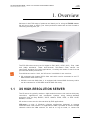
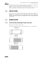
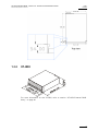
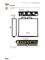
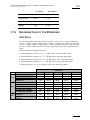
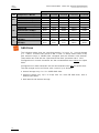
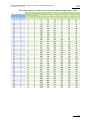
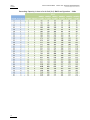
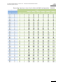
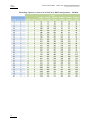
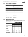
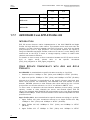
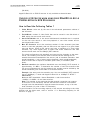
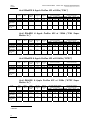
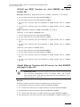
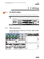
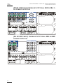
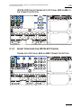
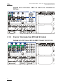

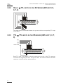
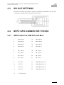
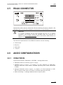
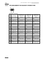
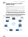
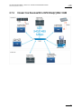
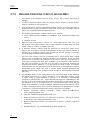
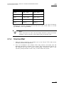
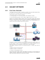
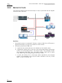
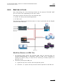
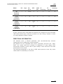
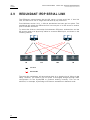
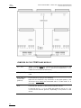
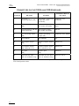
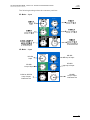
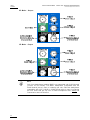
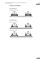
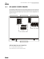
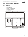
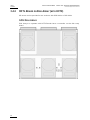
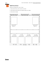
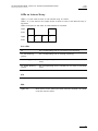
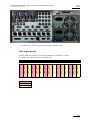
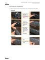

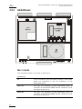


![2.8 conexión de varios servidores xt[2]](http://vs1.manualzilla.com/store/data/006305919_1-9948e093384d4040cdf0f68f445b7f43-150x150.png)

![XL[2] Technical Reference – Hardware](http://vs1.manualzilla.com/store/data/005956150_2-4515f3a1b925b4223206cf04092ab5bd-150x150.png)