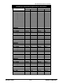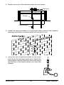
1
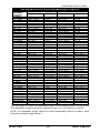
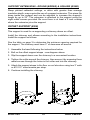
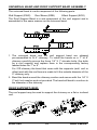
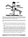
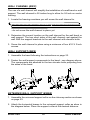
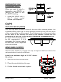
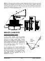
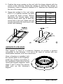
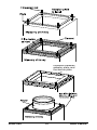
EXCEL FACTORY BUILT CHIMNEY INSTALLATION AND MAINTENANCE INSTRUCTIONS A MAJOR CAUSE OF CHIMNEY RELATED FIRES IS FAILURE TO MAINTAIN REQUIRED CLEARANCES (AIR SPACE) TO COMBUSTIBLE MATERIALS. IT IS OF UPMOST IMPORTANCE THAT THIS CHIMNEY BE INSTALLED ONLY IN ACCORDANCE WITH THESE INSTRUCTIONS. WARNING: There is a major risk of fire if loose fill insulation comes in contact with the chimney. It is particularly important to insure that there is NEVER any insulation above the radiation shield in the attic. This chimney is intended for use with solid, liquid and gas fired appliances, including wood fired stoves, fireplaces and furnaces. The chimney should be the size recommended by the appliance manufacturer. Use only ICC Model EXCEL components. Failure to do so will void the certification and warranty of the product. Keep these installation and operating instructions in a safe location for future reference. Contact local building or fire officials about restrictions and installation inspection in your area. EXCEL has been tested and listed to the UL-103HT chimney standard by Intertek Testing Services Listing # 3056610 ICC INDUSTRIAL CHIMNEY COMPANY INC 400 J.F. Kennedy, St. Jerome Quebec, Canada, J7Y 4B7 Tel.: (450) 565-6336 Fax: (450) 565-6519 www.icc-rsf.com FOR USA ONLY XLUSA-II_2012-01 Table of Contents TECHNICAL SPECIFICATIONS .................................................... 3 Creosote and Soot ......................................................................... 4 Coal ............................................................................................... 4 Wood and Coal Stoves ................................................................... 4 Operation and Maintenance ........................................................... 5 Chimney Fires ................................................................................ 5 Installation...................................................................................... 6 Factory built fireplaces ................................................................... 7 Chimney height .............................................................................. 7 INSTALLATION INSTRUCTIONS Typical installations ........................................................................ 8 Cathedral ceilings......................................................................... 10 Offset chimney ............................................................................. 12 Offset table, without adjustable length .......................................... 13 Offset table, with adjustable length ............................................... 14 Through wall Installation ............................................................... 15 Adjustable length (ELA18) ............................................................ 17 ACCESSORIES INSTALLATIONS SUPPORTS Round & square supports (ERDS & ESS)..................................... 18 Round support (ERDS) ................................................................ 18 Insulated round support (ERDSI) .................................................. 19 Support extensions (round ERDSE & square ESSE) .................... 22 Offset support (EOS) .................................................................... 22 Universal band & roof support band assembly .............................. 23 Roof support (ESR) ...................................................................... 23 Wall channel (EWC) ..................................................................... 25 Wall support (EWS)...................................................................... 25 Extended wall support (EWSE) .................................................... 25 Roof brace (ERB) ......................................................................... 26 RADIATION SHIELDS Wall radiation shield (EWRS) ....................................................... 27 Insulated wall radiation shield (EWRSI) ........................................ 28 Radiation shield (ERS) ................................................................. 29 FLASHINGS Flexible base flashing (ELFA-B-C)................................................ 29 Metal roof flashing (EMFA-B-C) .................................................... 30 Universal storm collar (ESC) ........................................................ 32 Decorative cap flashing (EDCF) ................................................... 33 CAPS Rain cap base (ERCB) ................................................................. 33 Wind shield (ERCW) .................................................................... 33 Decorative cap - Round (EDCR)................................................... 34 Decorative cap - Square (EDCS) .................................................. 35 Decorative cap with EXCEL rigid chimney liner............................. 37 Revolving rain cap (ERRC) .......................................................... 37 MISCELLANEOUS Snow-barrier (ESW) ..................................................................... 38 Anchor plate (EAP) ...................................................................... 39 Anchor plate damper (EAPD) ....................................................... 40 Warranty ...................................................................................... 44 EXCEL USA 2 Owner’s Manual EXCEL TECHNICAL SPECIFICATIONS Materials: Exterior (casing): .016” Type 434 Stainless Steel Interior (flue): .016” Type 304 Stainless Steel Insulation: ICC “Thermoplus” Blanket Inside Diameter 5 Inch 6 Inch 7 Inch 8 Inch Outside diameter 7” 8” 9” 10” Weight/Foot (lb/ft.) 3.6 4.2 4.9 5.3 2” or as established by factory built supports and firestops Clearance to combustibles Rough Opening Required 10” X 10” 10” X 10” 11” X 11” 12” X 12” N/A 10” X 10” 11” X 11” 12” X 12” Roof support (ERS) 11” X 11” 12” X 12” 13” X 13” 14” X 14” Offset support (EOS) 11” X 11” 12” X 12” 13” X 13” 14” X 14” Radiation shields (ERS) 11” X 11” 12” X 12” 13” X 13” 14” X 14” Wall radiation shield (EWRS) 10” X 10” 10” X 10” 11” X 11” 12” X 12” Wall radiation shield (EWRSI) N/A 10” X 10” 11” X 11” 12” X 12” Round support (ERDS & ES) 65’ 55’ 50’ 45’ Square support (ESS) N/A 55’ 50’ 45’ Roof support (ERS) 65’ 55’ 50’ 45’ Wall support (EWS) 50’ 44’ 37’ 35’ Offset support (EOS) 35’ 30’ 27’ 25’ Extended wall support (EWSE) 23’ 20’ 17’ 16’ Round support (ERDS & ES) Square support (ESS) Maximum Support Capacity Radiation shields must be used at all floor joist and ceiling areas Maximum continuous flue gas temperature: Brief forced firing: Tested to: (3 x 10 minutes) EXCEL USA 3 1000°F 1400°F 2100°F Owner’s Manual CREOSOTE AND SOOT - Formation and need for removal When wood is burned slowly it produces tar and other organic vapors, which combine with expelled moisture to form creosote. The creosote vapors condense in the relatively cool chimney flue of a slow-burning fire. As a result, creosote residue accumulates on the flue lining. When ignited this creosote makes an extremely hot fire. COAL Some coals contain large quantities of Sulphur (up to 7%). When coal is burned, Sulphur and coal ash are deposited in the chimney flue. This deposit combines with moisture to form a highly corrosive acid (Sulphuric Acid). In order to protect your chimney, we recommend that you: 1. Burn only low Sulphur coals (less than 1% Sulphur). 2. Have your chimney cleaned within 48 hours of shutting down your stove at the end of the heating season. Be certain that all the soot is removed. WOOD AND COAL STOVES If you are planning to install a wood stove, we recommend that you: 1. Choose a stove that has a label of a recognized Testing Laboratory (such as WH, UL, ULC, CSA). The EPA approved, low emissions stoves are highly recommended. 2. Connect only one solid fuel burning appliance to a chimney. Do not connect an oil or gas burning appliance to a chimney venting a solid fuel burning appliance. 3. Never over fire your stove. If any part of the stove or stove pipe is glowing red, then you are over firing. Immediately close the stove’s damper until the system cools. The high temperatures caused by over firing can permanently damage the stove and stove pipe and may overheat nearby combustible walls and furniture. 4. Install the stove and stove pipe as described in the Installation Instructions accompanying the stove. BE CERTAIN TO MAINTAIN THE REQUIRED CLEARANCES TO COMBUSTIBLE CONSTRUCTION. 5. Keep your flue gases between 300°F and 500°F. This will maximize efficiency while minimizing condensation and creosote formation. 6. Do not burn sea driftwood. Salt is highly corrosive to all types of stainless steel. Do not burn treated lumber. EXCEL USA 4 Owner’s Manual OPERATION AND MAINTENANCE KEEP YOUR CHIMNEY CLEAN Wood stoves can quickly create large deposits of creosote in the chimney. Some wood stoves can create enough creosote in two weeks to cause a chimney fire. When using a wood stove, we recommend that you: 1. Initially inspect the chimney system weekly. From this you will learn how often it will be necessary to clean your chimney. 2. THE CHIMNEY SHOULD BE INSPECTED AT LEAST ONCE EVERY TWO MONTHS DURING THE HEATING SEASON to determine if creosote or soot has built up. When a maximum of 1/4” of creosote or soot has accumulated, it should be removed to reduce the risk of a chimney fire. 3. Have your chimney cleaned by a qualified chimney sweep. If you want to clean your chimney yourself, then; clean your chimney using a properly fitting nylon or steel brush. Do not use a brush that will scratch the stainless steel interior of the chimney. Use of an oversize brush may damage the chimney. 4. Do not expect chemical chimney cleaners to keep your chimney clean. Their use does not negate the necessity of periodically inspecting and cleaning your chimney. CHIMNEY FIRES If you are having a chimney fire, follow these steps: 1. Close all heater doors and combustion air controls. For fireplaces, block the fireplace opening with a non-combustible material (such as a steel sheet). 2. Alert your family to the possible danger. 3. If you require assistance, alert your fire department. 4. If possible, use a dry chemical fire extinguisher, baking soda or sand to control the fire. Do not use water as it may cause a dangerous steam explosion. 5. Watch for smoldering or fire on combustibles next to the stove, stove pipe and chimney. Check outside to ensure that sparks and hot embers coming out of the chimney are not igniting the roof. 6. Do not use the stove again until your chimney and stove pipe have been inspected by a qualified chimney sweep or Fire Department Inspector. EXCEL USA 5 Owner’s Manual INSTALLATION 1. The chimney is intended for use with cooking, heating and other low-heat appliances. 2. A chimney venting a fireplace or an incinerator shall not vent any other appliance. 3. The clearance between single wall stove pipe and unprotected combustible material must not be less than 18” (reference National Building Codes and NFPA 211). The distance between a vertical stove pipe and the ceiling may be less than 18” when it is installed with an EXCEL support. The reduced clearance in this area has been confirmed as part of the chimney safety testing. The distance between the horizontal stove pipe and a vertical wall may be less than 18” where the insulated chimney passes horizontally through the wall. The distance will be determined by the Wall Radiation Shield (WRS). 4. The maximum height of un-guyed chimney above the roof is 5 feet. 5. Portions of the chimney which may extend through accessible spaces shall be enclosed in all cases to avoid personal contact with the chimney and damage to the chimney. 6. Do not fill the air space around the chimney with insulation or any other material. Do not fill the factory built supports or radiation shields with insulation. Insulation placed in this area could cause adjacent combustibles to overheat. Do not allow sawdust or construction debris to accumulate around the chimney. Clean all areas surrounding the chimney before closing up any enclosed areas. 7. The chimney shall extend at least 3 ft. above its point of penetration with the roof and at least 2 ft. higher than any wall, roof or adjacent building within 10 ft. of it. For chase installations, the chimney must extend at least 8” above the top of the chase. 8. The following does not apply to installation in single and two-family dwellings: Factory built chimneys which extend through any story above that on which the connected appliance is located are to be provided with enclosures having a fire resistance rating equal to or greater than that of the floor or roof assemblies through which they pass. EXCEL USA 6 Owner’s Manual FACTORY BUILT FIREPLACE When Excel is approved with a factory-built fireplace, the chimney and fireplace are tested in combination, as a complete system. It is not possible to include specific installation instructions for each make and model of fireplace in these instructions, you must follow the instructions included with the fireplace you are installing. CHIMNEY HEIGHT The minimum height of chimney required is the same for all support styles and sizes. The diagram below shows minimum chimney height as required by code. A quick way to calculate this dimension is to multiply the vertical rise per 12” of horizontal distance (X in the diagram) by 10 and add 24”. When the chimney is installed within 10’ of the peak it must clear the peak by 24”. The minimum chimney height is 3’. EXCEL USA 7 Owner’s Manual INSTALLATION INSTRUCTIONS TYPICAL INSTALLATIONS If the support is installed in a ceiling with an attic directly above, the support also acts as the attic radiation shield when installed with an universal storm collar (ESC). 1. Locate the chimney in a convenient place as near as possible to the appliance outlet. Cut and frame the holes in the floor, ceiling and roof where the chimney will pass. Refer to the technical specifications on page 3 to determine the required rough opening for the support model and size you are installing. NOTE - Look Up - The round and square supports are designed to protect the surrounding combustible materials and as a result they permit 1” clearance from the chimney to combustible framing - in the area that they protect. When these supports are installed in a roof truss insure that the chimney has 2” clearance at the top of the truss. This may require you to block out the support at the bottom. Another option is to install a support extension (see page 22). Trim the support extension flush with the roof, this will permit the chimney to pass within 1” of the truss. 2. From below, push the support into the framed hole. The support must protrude at least 3” below the finished ceiling. Nail the support to the framed joist using 8 - 3” spiral nails or # 8 X 1 1/2” wood screws. Place the Finish Collar around the support and fasten it to the ceiling using the two screws provided. Note: If you are using a 6” square support you may find it difficult to screw it in place because there is not much room inside it. We have provided angle brackets with this support which can be screwed to the outside of the support box and nailed to surrounding framing as required. Use a minimum of four # 8 X 1/2” screws per bracket. In some cases these brackets may need to be trimmed (e.g.: to fit under a flashing). 3. Fasten the flue extension (EX) to the first length of chimney with the three screws provided. Place the first section of chimney into the support with the flue extension protruding through the hole in the support. When installing additional sections of chimney line up the vertical seams to insure that the pre-punched screw holes line up with the slots in the outside casing. If the chimney passes through additional floors above the support follow instruction 4. If the chimney passes directly into the attic without going through another floor proceed to instruction 5. EXCEL USA 8 Owner’s Manual 4. Install additional chimney lengths as required making sure that you install a radiation shield (ERS) where the chimney penetrates the ceiling - the ERS should be installed from the bottom, screw or nail the ERS solidly to the framing. EXCEL USA 9 Owner’s Manual 5a. IF THE CHIMNEY IS NOT ENCLOSED IN THE ATTIC: Install a universal storm collar (ESC) on top of the support or radiation shield (ERS). This will prevent loose insulation from falling into the area between the chimney and the support or radiation shield. Install a regular roof flashing. Go to instruction 6. 5b. IF THE CHIMNEY IS ENCLOSED IN THE ATTIC: Install a radiation shield (ERS) at the attic joist. Continue installing chimney sections up through the roof opening and install a vented flashing on the roof. 6. Install the roof flashing. Seal the joint between the roof and the flashing with roofing tar or silicone. For sloping roofs, place the flashing under the upper shingles and on top of the lower shingles -approximately half of the flashing should be under the shingles. Seal the joint between the roof and the flashing with roofing tar or silicone. Nail the flashing to the roof using roofing nails. Place the universal storm collar (ESC) over the chimney and the flashing. Tighten it in place. Caulk the joint between the chimney and storm collar with silicone. 7. Continue adding chimney sections until the required chimney height is reached. See the drawing on page 7 to determine the correct height. 8. If the chimney height above the roof exceeds 5 feet then a roof brace (ERB) must be installed. 9. Fit the rain cap to the top of the chimney. Screw the four metal screws provided through the straps and into the top chimney length. CATHEDRAL CEILINGS If your home has a cathedral ceiling (no attic space between the ceiling and the roof), install the chimney and support as follows. 1. Situate the chimney in a convenient location as near as possible to the appliance outlet. Cut and frame a hole in the roof for the support. The sides of this hole must be vertical (see page 3 for hole size). 2. Place the support in the opening. Lower it to the correct height as determined by the table and diagram below. Using a level, make sure the support is vertical. If the support extends above the roof, cut it flush with the top of the roof. Nail the support to the frame opening using 8 - 3” spiral nails or # 8 X 1 1/2” screws. Note: if you are using a 6” square support you may find it difficult to screw it in place because it is fairly small inside. We have provided angle brackets EXCEL USA 10 Owner’s Manual with this support which can be screwed to the outside of the support box and nailed to surrounding framing as required. Use a minimum of four # 8 X 1/2” screws per bracket. In some cases these brackets may need to be trimmed (e.g.: to fit under a flashing). Place the finish collar around the support and fasten it to the ceiling using the screws provided. 3. Attach the flue extension (found in the support box) to the bottom of the first chimney length using the 3 metal screws provided. Put this chimney length in the support. Push it down firmly in place. 4. Use a regular roof flashing. Put the roof flashing in place. Place the flashing under the upper shingles and on top of the lower shingles approximately half of the flashing should be under the shingles. Seal the joint between the roof and the flashing with roofing tar or silicone. Nail the flashing to the roof using roofing nails. Place the universal storm collar over the chimney and flashing. Caulk the joint between the chimney and collar with silicone caulking. 5. Put the remaining required lengths of chimney in place. Fasten the lengths together using three metal screws at each joint (provided with the chimney). If the chimney extends more than 5 feet above the roof, install a roof brace. 6. Fit the rain cap to the top of the chimney. Screw the four metal screws provided through the straps and into the top chimney length. SLOPE X 0/12 - 2/12 3” 2/12 - 7/12 51/2” 7/12 - 12/12 63/4” 12/12 - 24/12 71/2” 24/12+ 121/2” EXCEL USA 11 Owner’s Manual OFFSET CHIMNEY If it is necessary to offset the chimney in order for it to pass through an upstairs cupboard or to clear a joist, do this by using 15°or 30° insulated elbows. The maximum number of elbows permitted is four (typically this would consist of two sets of an offset and a return). To determine the parts required for your installation refer to the drawing below and the offset tables on page 13 and 14. You may find it convenient to install an adjustable length (ELA18) between the elbows. This will allow you to offset the exact distance you require. The offset table on page 13 should be used when no adjustable length is required. Use the table on page 14 when an adjustable length is required. The maximum length of unsupported offset chimney is 8’. If the offset chimney is longer than 8’, then it must be supported at 6’ intervals using an offset support (EOS). When you reach the height at which the elbow will be installed, proceed as follows: 1. Install the insulated elbow on the chimney length. Turn it in the required direction and fasten it to the chimney with the 3 metal screws provided. Since the offset direction varies from installation to installation the pre-punched holes will not line up. 2. Place the required length of chimney on the elbow. Fasten it to the elbow with the three metal screws provided. 3. Use another elbow to turn the chimney vertically. Again secure the elbow to the chimney length using three metal screws. 4. Install the remaining chimney as described in the support instructions. 5. An Offset or Roof Support must be installed above each offset (two elbows) to support the chimney above the offset. This support may be installed on any convenient location on the vertical run above the offset. EXCEL USA 12 Owner’s Manual All dimensions are in inches EXCEL OFFSET TABLE – Use this table if you are not installing an adjustable length between the elbows. LENGTH BETWEEN OFFSETS 5 INCH Ø NO LENGTH 6” Length 12” Length 18” Length 24” Length 48” Length 24” + 12” 48” + 12” 48” + 18” 48” + 24” 48”+24”+12” 48” + 48” 6 INCH Ø NO LENGTH 6” Length 12” Length 18” Length 24” Length 48” Length 24” + 12” 48” + 12” 48” + 18” 48” + 24” 48”+24”+12” 48” + 48” 7 INCH Ø NO LENGTH 6” Length 12” Length 18” Length 24” Length 48” Length 24” + 12” 48” + 12” 48” + 18” 48” + 24” 48”+24”+12” 48” + 48” 8 INCH Ø NO LENGTH 6” Length 12” Length 18” Length 24” Length 48” Length 24” + 12” 48” + 12” 48” + 18” 48” + 24” 48”+24”+12” 48” + 48” EXCEL USA 15° Elbows 30° Elbows RISE OFFSET RISE OFFSET 9 1/4 13 1/4 19 25 30 3/4 53 3/4 40 1/2 63 3/4 69 1/2 75 1/4 85 1/4 98 1/2 1 1/4 2 1/4 3 3/4 5 1/2 7 13 1/4 10 1/2 14 1/4 19 1/4 24 1/2 29 3/4 50 1/2 9 1/2 15 3/4 17 1/2 19 21 1/2 25 1/4 38 3/4 59 1/2 64 1/2 69 3/4 78 3/4 90 1/2 2 3/4 5 8 11 14 26 19 9 1/2 13 1/2 19 1/4 25 1/4 31 54 40 3/4 64 69 3/4 75 1/2 85 1/2 98 3/4 1 1/4 2 1/4 4 5 1/2 7 13 1/4 9 3/4 15 3/4 17 1/2 19 21 3/4 25 1/4 11 14 3/4 19 3/4 25 30 1/4 51 39 1/4 60 65 70 1/4 79 1/4 91 3 5 8 11 14 26 19 1/4 31 1/4 34 1/4 37 1/4 42 1/4 49 1/4 9 3/4 13 3/4 19 1/2 25 1/2 31 1/4 54 1/2 41 64 1/4 70 75 3/4 85 3/4 99 1 1/4 2 1/2 4 5 1/2 7 13 1/4 9 3/4 16 17 1/2 19 21 3/4 25 1/4 11 1/2 15 1/4 20 1/4 25 1/2 30 3/4 51 1/2 39 3/4 60 1/2 65 1/2 70 3/4 79 3/4 91 1/2 3 5 1/4 8 1/4 11 1/4 14 1/4 26 1/4 19 1/4 31 1/4 34 1/4 37 1/4 42 1/2 49 1/4 10 14 19 3/4 25 3/4 31 1/2 54 3/4 41 1/4 64 1/2 70 1/4 76 1/4 86 99 1/4 1 1/4 2 1/2 4 5 1/2 7 13 1/4 9 3/4 16 17 1/2 19 21 3/4 25 1/4 12 15 3/4 20 3/4 26 31 1/4 52 40 1/4 61 66 71 1/4 80 1/4 92 3 1/4 5 1/4 8 1/4 11 1/4 14 1/4 26 1/4 19 1/2 31 1/2 34 1/2 37 1/2 42 1/2 49 1/2 13 31 34 37 42 1/4 49 Owner’s Manual All dimensions are in inches Use this table when an 18 inch adjustable length is required. LENGTH BETWEEN OFFSETS 5 INCH Ø 6” Length 12” Length 18” Length 24” Length 48” Length 24” + 12” 48” + 12” 48” + 18” 48” + 24” 48”+24”+12” 48” + 48” 6 INCH Ø 6” Length 12” Length 18” Length 24” Length 48” Length 24” + 12” 48” + 12” 48” + 18” 48” + 24” 48”+24”+12” 48” + 48” 7 INCH Ø 6” Length 12” Length 18” Length 24” Length 48” Length 24” + 12” 48” + 12” 48” + 18” 48” + 24” 48”+24”+12” 48” + 48” 8 INCH Ø 6” Length 12” Length 18” Length 24” Length 48” Length 24” + 12” 48” + 12” 48” + 18” 48” + 24” 48”+24”+12” 48” + 48” 15° Elbows 30° Elbows RISE OFFSET RISE OFFSET 23 - 28 3/4 28 3/4 - 34 1/2 34 1/2 - 40 1/4 40 1/4 - 46 1/4 63 1/2 - 69 1/4 50 1/4 - 56 73 1/2 - 79 1/4 79 1/4 - 85 85 - 90 3/4 95 - 100 3/4 108 1/4 - 114 5 - 6 1/2 6 1/2 - 8 8 - 9 1/2 9 1/2 - 11 15 3/4 - 17 1/4 12 1/4 - 13 3/4 18 1/2 - 20 20 - 21 1/2 21 1/2 - 23 24 1/4 - 25 3/4 27 3/4 - 29 1/4 22 3/4 - 28 28 - 33 1/4 33 1/4 - 38 1/2 38 1/2 - 43 1/2 59 1/4 - 64 1/2 47 1/4 - 52 1/2 68 - 73 1/4 73 1/4 - 78 1/2 78 1/2 - 83 3/4 87 1/4 - 92 1/2 99 1/4 - 104 1/2 10 - 13 13 - 16 16 - 19 19 - 22 31 - 34 24 - 27 36 - 39 39 - 42 42 - 45 47 1/4 - 50 1/4 54 - 57 23 1/4 - 29 29 - 34 3/4 34 3/4 - 40 1/2 40 1/2 - 46 1/2 63 3/4 - 69 1/2 50 1/2 - 56 1/4 73 3/4 - 79 1/2 79 1/2 - 85 1/4 85 1/4 - 91 95 1/4 - 101 108 1/2 - 114 1/4 5 - 6 1/2 6 1/2 - 8 8 - 9 1/2 9 1/2 - 11 1/4 15 3/4 - 17 1/4 12 1/4 - 13 3/4 18 1/2 - 20 20 - 21 1/2 21 1/2 - 23 24 1/4 - 25 3/4 27 3/4 - 29 1/4 23 1/4 - 28 1/2 28 1/2 - 33 3/4 33 3/4 - 39 39 - 44 59 3/4 - 65 47 3/4 - 53 68 1/2 - 73 3/4 73 3/4 - 79 79 - 84 1/4 87 3/4 - 93 99 3/4 - 105 10 - 13 13 - 16 16 - 19 19 - 22 31 - 34 24 1/4 - 27 1/4 36 1/4 - 39 1/4 39 1/4 - 42 1/4 42 1/4 - 45 1/4 47 1/4 - 50 1/4 54 1/4 - 57 1/4 23 1/2 - 29 1/4 29 1/4 - 35 35 - 40 3/4 40 3/4 - 46 3/4 64 - 69 3/4 50 3/4 - 56 1/2 74 - 79 3/4 79 3/4 - 85 1/2 85 1/2 - 91 1/4 95 1/2 - 101 1/4 108 3/4 - 114 1/2 5 - 6 1/2 6 1/2 - 8 8 - 9 1/2 9 1/2 - 11 1/4 15 3/4 - 17 1/2 12 1/4 - 13 3/4 18 1/2 - 20 20 - 21 1/2 21 1/2 - 23 1/4 24 1/4 - 25 3/4 27 3/4 - 29 1/4 23 3/4 - 29 29 - 34 1/4 34 1/4 - 39 1/2 39 1/2 - 44 1/2 60 1/4 - 65 1/2 48 1/4 - 53 1/2 69 - 74 1/4 74 1/4 - 79 1/2 79 1/2 - 84 3/4 88 1/4 - 93 1/2 100 1/4 - 105 1/2 10 1/4 - 13 1/4 13 1/4 - 16 1/4 16 1/4 - 19 1/4 19 1/4 - 22 1/4 54 - 57 1 1/2 - 4 1/2 36 1/4 - 39 1/4 39 1/4 - 42 1/4 42 1/4 - 45 1/4 47 1/2 - 50 1/2 54 1/4 - 57 1/4 23 3/4 - 29 1/2 29 1/2 - 35 1/4 35 1/4 - 41 41 - 47 64 1/4 - 70 51 - 56 3/4 74 1/4 - 80 80 - 85 3/4 85 3/4 - 91 1/2 95 3/4 - 101 1/2 109 - 114 3/4 5 - 6 1/2 6 1/2 - 8 8 - 9 3/4 9 3/4 - 11 1/4 15 3/4 - 17 1/2 12 1/4 - 13 3/4 18 1/2 - 20 20 - 21 3/4 21 3/4 - 23 1/4 24 1/4 - 25 3/4 27 3/4 - 29 1/2 24 1/4 - 29 1/2 29 1/2 - 34 3/4 34 3/4 - 40 40 - 45 60 3/4 - 66 48 3/4 - 54 69 1/2 - 74 3/4 74 3/4 - 80 80 - 85 1/4 88 3/4 - 94 100 3/4 - 106 10 1/4 - 13 1/4 13 1/4 - 16 1/4 16 1/4 - 19 1/4 19 1/4 - 22 1/4 31 1/4 - 34 1/4 24 1/2 - 27 1/2 36 1/2 - 39 1/2 39 1/2 - 42 1/2 42 1/2 - 45 1/2 47 1/2 - 50 1/2 54 1/2 - 57 1/2 The best place to install the adjustable length is immediately below the top elbow. The adjustable length can then be adjusted to give you the offset you require. NOTE: An adjustable length cannot be used immediately above an elbow, there must be a straight length below it. EXCEL USA 14 Owner’s Manual THROUGH WALL INSTALLATION Unenclosed Exterior Installation Enclosed Exterior Installation 1. Determine where the chimney will pass through the wall. For concrete walls cut a hole slightly larger than the chimney. If the concrete wall has a wood wall inside it follow the instructions for a combustible wall. For combustible walls cut and frame a hole corresponding to the rough opening required in the table on page 3. 2. Combustible wall: From outside, put the exterior portion (the galvanized part with the square plate) of the wall radiation shield in the hole. Nail the shield in place using 4 - 2” nails or # 8 X 1 1/2” wood screws. Seal the joint between the shield and the wall with silicone caulking. 3. Assemble the Wall Support (EWS or EWSE) - follow instructions on page 25. 4. Fasten the required chimney length to the Tee side entrance. The horizontal chimney section must extend through the finished interior wall by at least 4 inches. In some cases it you may wish to use an adjustable length (ELA18) in combination with a short length for this purpose. Attach the flue extension (EX) - found in the EWRS or EWRSI box, to the end of the horizontal chimney length using the 3 metal screws provided. EXCEL USA 15 Owner’s Manual 5. Fasten a chimney length to the top of the Tee. 6. The wall support should be installed on the first vertical chimney section above the Tee. Tighten the universal band locking bolt just enough to hold the wall support in place. 7. Install this assembly through the hole in the radiation shield. 8. Fasten the Wall Support brackets to the outside wall in a convenient location directly above the hole. Use 4 - #10 X 3” or larger screws. Insure that the screws are fastened into a structural member and not only to the wall sheeting. If the stud locations do not line up properly you may wish to use a wall channel - see instructions page 25. The Wall Support brackets are slotted to allow them to adjust in and out. Adjust the brackets so that the chimney is a minimum of 2” from the wall and parallel with it. Tighten the Wall Support collar around the chimney, then secure it using 3 metal screws. 9. Stack the next chimney length in place. Align the vertical seams, this will also align the screw holes. Fasten the lengths together using 3 metal screws. Continue installing lengths until you reach the roof or until the required overall height is achieved. Many installers prefer to screw two or three vertical lengths together in advance because it is easier to screw the chimney sections together in the open than when they are close to a wall. If the chimney is installed in a combustible chase then a ventilated flashing (EVF) must be installed - see drawing on page 15. 10. If the chimney passes through the roof, cut a hole large enough to provide 2” clearance between the chimney and the roof. Install a radiation shield (ERS) from the bottom to seal the opening. Continue installing lengths as required. 11. Install another Wall Support at 8’ intervals. The Wall Support should be adjusted to ensure the chimney is vertical and at 2” (or more) clearance to combustibles. 12. Put the roof flashing in place. Seal the joint between the roof and the flashing with roofing pitch. For sloping roofs, place the flashing under the upper shingles and on top of the lower shingles. Nail the flashing to the roof using roofing nails. Place the universal storm collar (ESC) over the chimney just above the flashing. Caulk the joint between the chimney and storm collar with silicone caulking. EXCEL USA 16 Owner’s Manual 13. Continue adding chimney sections until the required chimney height is reached. See the drawing on page 7 to determine the correct height. 14. If the chimney extends more than 5’ above the roof it should be secured to the roof using a Roof Brace (ERB). 15. Fit the rain cap to the top of the chimney. Screw the four metal screws provided through the straps and into the top chimney length. Install the spark screen if you wish to have a spark screen. 16. FROM INSIDE. Slide the black portion of the Wall Radiation Shield over the galvanized portion which was installed from the outside and push it until it stops against the chimney. The black interior portion of the Wall Radiation Shield must project into the room a minimum of 4”. Install the round finish trim with the long black screws provided. NOTES: 1. The chimney may be enclosed or un-enclosed. Always maintain 2” clearance to combustible materials. Do not fill the space around the chimney with insulation or any other material. 2. A wall support must be used to secure the chimney to the wall. Maximum distance between wall supports is 8 feet if the chimney is not enclosed. 3. The chimney must extend in to the room at least 4 inches. 4. The distance between a single wall stovepipe and a parallel combustible wall or ceiling must not be less than 18”. The distance between the horizontal stove pipe and the un-shielded vertical wall through which the insulated chimney passes is determined by the Wall Radiation Shield. 5. If an exterior installation is to be enclosed, allow for access to the base of the Tee to facilitate cleaning. 6. The minimum distance between the bottom of the chimney and any horizontal combustible is 12”. ADJUSTABLE LENGTH (ELA18) An adjustable chimney length is available for chimney installations that require exact lengths. An adjustable length cannot be installed immediately above a support, elbow or tee. It can only be installed above a straight length. When using the adjustable length the flue (inside) does not adjust, only the outside casing. EXCEL USA 17 Owner’s Manual 1. Determine the required length. 2. Remove the three screws from the outside casing of the adjustable length. Slide the two sections of the outer casing together until the required overall length is achieved. 3. Using the stainless steel screws provided fasten the two sections of outer casing together through the three pre-punched holes. The screws are self drilling and will make their own holes. Cut off the exposed insulation. The remaining insulation will compress enough to allow the next chimney section to connect. Do not cut the inner flue, it will slide inside the next chimney length. 4. To install the adjustable length slide the flue into the length below until the outside casing seats firmly in place. You may need to press firmly to compress the additional insulation. Fasten the lengths together using the 3 metal screws provided. ACCESSORIES INSTALLATIONS SUPPORTS ROUND SUPPORT (ERDS) & SQUARE SUPPORT (ESS) If you are installing your chimney in an energy efficient house which has sealed vapor barriers (eg: R2000 construction) we manufacture a special round support so that you can maintain your vapor barrier integrity. See part (ERDSI). The ERDSI comes with its own set of installation instructions. Typical round and square support installations are shown in drawings 1 thru 4 on page 9. The clearance between the chimney and combustible material must not be less than 2” except for areas protected by the support. Do not fill this area with insulation. If the support is installed in a cathedral ceiling, follow the instructions for Cathedral Ceilings. ROUND SUPPORT (ERDS) To install the round support using the support collar follow the Excel installation instructions for the round support replacing step #2 with the following: EXCEL USA 18 Owner’s Manual 1. Slide the support collar over the support from the bottom making sure the four tabs are pointing downwards - see drawing below. Before screwing the collar in place you must measure to compensate for the thickness of the framing materials and also insure that the bottom of the support extends a minimum of 3” below the finished ceiling. Fasten the collar to the support with the self tapping metal screws provided. 2. The tabs have been designed so that the support can be pushed up through the square framed opening from the bottom and then rotated 1/4 turn so that the tabs sit on top of the framing - the round trim collar is large enough to cover the square hole. Once all four tabs are sitting on the framing it must be nailed or screwed in place. This can be accomplished either from the top through the holes in the tabs, or through all four sides of the support using a minimum #8 X 1 1/2” screws. To complete the installation follow the remaining steps in the Excel installation instructions. INSULATED ROUND SUPPORT (ERDSI) These instructions are supplementary to the detailed installations instructions which come with every Excel system. To complete the installation correctly you must have both sets of instructions. 1. Frame the opening for the support - see table in page 3 of the Excel installations instructions for the correct size. 2. Carefully cut an X in the vapor barrier so that it can be folded in to the framed opening and fasten it. 3. Apply acoustic sealant to the insulated firestop. Be sure to place the sealant so that the screw holes in the firestop will be sealed. Push the insulated firestop up from the bottom so that the sealant is compressed against the vapor barrier. Fasten in place with four drywall nails or screws. EXCEL USA 19 Owner’s Manual 4. Apply the drywall and carefully cut a round hole to accommodate the round support being carefully not to pierce the vapor barrier. Insulation wrap assembly. NOTE: The drawing shows the chimney length as it is installed in the support, however it is easier to install the flue extension and the insulation wrap with the chimney section inverted. 5. Place the first chimney length (#1) on a flat surface with the female end facing upwards. Attach the flue extension (#2) using the 3 metal screws provided. Place the insulation blanket (#3) flush with the bottom of the chimney section. Connect the clamp straps and tighten them until it is possible to slide the chimney, so the insulation wrap and the flue extension installed, into the support (#4). EXCEL USA 20 Owner’s Manual 6. You may insulate right up to the support inside the framed opening. Under no circumstances can insulation be permitted to come in contact with the chimney directly (eg: above the top of the support). If the insulation depth exceeds the height of the support you must install a support extension (RDSE) to keep the insulation away from the chimney. 7. Insure that there is no debris or insulation between the chimney and the support. Install a storm collar immediately above the support to keep loose insulation and debris from falling into the support. 8. From inside the room seals the joint between the support and the insulated firestop with silicone. Install the trim collar - be sure to seal the screw holes with silicone. EXCEL USA 21 Owner’s Manual SUPPORT EXTENSIONS - ROUND (ERDSE) & SQUARE (ESSE) Steep pitched cathedral ceilings, or attics with greater than average insulation depth, may require the use of a support extension. This piece fits down inside the support and can be adjusted to increase the support’s length by up to 22”. The extension is attached to the support using the eight metal screws provided. Be sure there is at least a 2 inch overlap where the extension joins the support. OFFSET SUPPORT (EOS) This support is used for re-supporting a chimney above an offset. Install the chimney and elbows according to the installation instructions. Install the support as follows: See the table on page 3 to determine the minimum opening required for the support. The chimney must have 2” of clearance all around. 1. Assemble the band following the instructions below. 2. Bolt on the offset support straps - see diagram above. 3. Slip the support down over the chimney to a convenient location. 4. Tighten the collar around the chimney, then secure it by screwing three metal screws through the holes in the collar and into the chimney. 5. Attach the support straps to the floor or roof structure using two 3” nails or #10 X 2” wood screws per strap. 6. Continue installing the chimney. EXCEL USA 22 Owner’s Manual UNIVERSAL BAND AND ROOF SUPPORT BAND ASSEMBLY The universal band is a sub-component of the following parts: Wall Support (EWS) Roof Brace (ERB) Offset Support (EOS) The Roof Support Band is a sub-component of the roof support and is assembled in the same manner as the universal band. 1. The universal band and the roof support band are shipped pre-assembled to fit 6” chimney. To install the bands on a 7” or 8” chimney carefully remove the three 1/4” X 1” elevator bolts (five bolts for a roof support) and replace them in the corresponding factory labeled holes for 7” or 8”. For 5”Ø chimney the band that come with the supports (wall, roof or offset) and with the roof brace is made to fit the outside diameter of the 5” chimney only. 2. Bend the band around the chimney section and secure with the 1/4” X 2” bolt, lock washer and nut provided. The band will bend to conform to the diameter of the chimney. ROOF SUPPORT (ESR) The roof support may be used to support the chimney on a flat or inclined roof. EXCEL USA 23 Owner’s Manual When using a roof support the chimney must extend in to the room a minimum of 6 inches below a finished ceiling. You must also maintain the required horizontal clearance between the single or double wall connector and the combustible ceiling - see diagram below. See the table on page 3 to determine the minimum opening required in the roof. The chimney must have 2” of clearance all around - regardless of roof pitch. 1. Assemble the roof support band following the instructions on page 23. 2. Bolt on the two 90° roof support brackets. These brackets require two elevator bolts per bracket - see the drawing above. Leave these bolts loose. 3. Slip the support down over the chimney - locate the support on the chimney so that the required amount of chimney projects below the finished ceiling - tighten the locking nut. Place the chimney in the opening in the roof. Rotate the 90° brackets to adjust for the roof pitch. Tighten the collar around the chimney, then secure it by screwing three metal screws through the holes in the collar and into the chimney. Tighten the four nuts which hold the brackets to the support band. 4. Centre the chimney in the hole in the roof and nail or screw the support to the roof using 6 - 2 1/2” nails or # 8 X 1 1/2” wood screws. EXCEL USA 24 Owner’s Manual WALL CHANNEL (EWC) The use of a wall channel will simplify the installation of a wall band or wall support. The wall channel is 26 inches long to allow for 24 inch on centre framing. 1. Locate the framing members you will screw the wall channel to. - do not screw the wall channel in place yet. 2. Determine the correct location on the wall channel for the wall band or wall support. The two short sides of the wall channel rest against the wall. Bolt the support brackets to the wall channel with elevator bolts. 3. Screw the wall channel in place using a minimum of four #10 X 3 inch screws. WALL SUPPORT (EWS) 1. Assemble the band following the instructions on page 23. 2. Fasten the wall support components to the band - see diagram above. The components are attached to the two elevator bolts projecting from the sides of the band. EXTENDED WALL SUPPORT (EWSE) 1. Assemble the universal support collar on the chimney section as shown on page 23. 2. Attach the horizontal braces to the universal support collar as show in the diagram below. Place the support collar at the desired distance EXCEL USA 25 Owner’s Manual from the wall using the slots on the horizontal braces. The braces are attached to the two elevator bolts that protrude from the sides of the support collar. Continue the installation in accordance with the instruction manual on page 15, wall support, and replace instructions 6 and 8 on page 16 with the following: 3. The horizontal braces and support flange should be installed on the first vertical chimney section above the Tee. Tighten the universal band locking bolt just enough to hold the wall support in place. 4. Install the support horizontal braces on the external wall by using four #10 X 3” or longer screws. Attach the diagonal braces and the wall brackets to the horizontal braces. Install the brackets on the external wall using #10 X 3” or longer screws. As mentioned previously, ensure that the screws are anchored in the structural member and not only to the wall sheeting. If the stud locations do not line up properly you may wish to use a wall channel (see Chimney Maximum instructions page 25). The wall support height that diameter brackets are slotted to allow them to adjust can be in and out. Adjust the brackets so that the supported chimney is a minimum of 2” from 5” Ø 23’ combustible material and parallel with the 6” Ø 20’ wall. Tighten the Wall Support collar around 7” Ø 17’ the chimney and then secure it using 3 8” Ø 16’ metal screws. (continue the installation in accordance with the instruction manual at the page 16) ROOF BRACE (ERB) The roof brace is required to provide extra stability for chimneys which extend more than 5 feet above a roof. 1. Assemble the band following the instructions on page 23. EXCEL USA 26 Owner’s Manual 2. Place the band at a point at least two thirds of the way up the chimney. Fasten the larger diameter section of the braces to the collar using the nuts provided. Adjust the length of the braces by telescoping one tube inside the other until the desired length is reached. The angle of the braces should not be more than 45 degrees from horizontal when fastened to the roof. 3. Fasten the other end of each brace to the roof using a # 10 X 4” or larger screw and a washer. Insure that the screws are fastened into a structural member of the roof and not only into the roof sheeting. The two braces should be installed approximately 90° apart. 4. Tighten the bolt which locks the two tubes together very firmly. We recommend that you screw the inside and outside tubes together using # 8 X 1/2” screws to permanently lock them in place. 5. Tighten the locking bolt on the universal band then secure the collar by screwing the metal screws provided through the holes in the collar and into the chimney. RADIATIONS SHIELDS WALL RADIATION SHIELD (EWRS) If you are installing your chimney in an energy efficient house which has sealed vapor barriers (e.g.: R2000 construction) we manufacture a special wall radiation shield so that you can maintain your vapor barrier integrity: the insulated wall radiation shield (EWRSI). If possible install an interior chimney as it will provide better performance than an exterior chimney. In area with continuous temperatures below -18°C (0°F) the use of an exterior chimney may result in operating problems such as poor draft, excessive condensation of combustion products and rapid accumulation of creosote when connected to a wood EXCEL USA 27 Owner’s Manual burning appliance. If you do install an exterior chimney, we recommend that you enclose it using an insulated enclosure. See the drawing for the installation sequence of each part and refer to page 15 for the overall installation. INSULATED WALL RADIATION SHIELD (EWRSI) The insulated radiation shield can be used in any “through the wall” installation just as the wall radiation shield (EWRS). See the drawing for the installation sequence of each part. Make sure to install the insulated firestop on the inside side of the wall. The gypsum board goes over the insulated firestop. EXCEL USA 28 Owner’s Manual RADIATION SHIELD (ERS) The radiation shield must be used when the chimney passes through a floor, or when it is installed in a attic (see illustrations on page 9). The radiation shield is designed to adjust for a variety of attic heights. Always adjust the radiation shield to be as high as the attic will allow, even if the additional height is not required to provide shielding from insulation. This will reduce the chance that loose fill insulation will come in contact with the chimney if additional insulation is added in the future. To adjust the radiation shield simply slide the top tube up as high as possible then screw the two sections together with the self drilling screws provided. When the radiation shield is installed in the attic, a universal storm collar (ESC) must be used. This will prevent the infiltration of insulation between chimney and radiation shield. FLASHINGS FLEXIBLE BASE FLASHING (ELFA-B-C) WARNING: WEAR GLOVES TO MANIPULATE THE FLASHING. 1. Align the centerline of the flashing with the centerline of the chimney. 2. Trace a line on the roof corresponding to the interior of the flashing cone. 3. Remove the flashing and cut a hole in the roof tiles and roof sheeting following the line. Make sure to provided 2” clearance between the chimney and combustibles material. Note: a rectangular opening would also be adequate. 4. Slide the top of the flashing under the upper tiles and let the bottom of the flashing rest on the roof. Firmly press the base of the flashing against the roof so that it matches the profile of the roof. 5. Seal the bottom of the cone along the base of the flashing with a good quality exterior sealant. 6. Install the storm collar, as described on page 10. EXCEL USA 29 Owner’s Manual METAL ROOF FLASHING (EMFA-B-C) 1. Align the centerline of the flashing with the centerline of the chimney. 2. Trace a line on the metal roof corresponding to the interior of the flashing cone. 3. Remove the flashing and cut a hole in the metal roof deck and roof sheeting following the line. Make sure to provided 2” clearance between the chimney and combustibles material. Note: a rectangular opening would also be adequate. 4. Cut a slot in the metal roofing at the top (peak) side of the hole and parallel with the peak. The slot should be approximately 1/8” wide (centered over the hole): See the table below for adequate length. 5. Slide the top of the flashing into the slot and let the bottom of the flashing rest on the roof. EXCEL USA 30 Owner’s Manual 6. Trace the profile of the roof ridges on to the vertical portion of the flashing base and then notch the flashing to correspond with the roof (Drawing 4). 7. Seal the side flanges of the flashing with an external grade sealant. 8. Fasten the flashing to the roof with a minimum of 6 x # 8 wood screws, sealed with metal/rubber washers or silicone. 9. Install the storm collar, as described on page 10. CODE EMFA 5-6-7-8” EMFB 5-6” EXCEL USA 31 LENGTH OF SLOT 23” EMFB 7” 24 1/4” EMFB 8” EMFC 5-6-7-8” 25 1/4” Owner’s Manual UNIVERSAL STORM COLLAR (ESC) The universal storm collar has been designed as a compatible fit for all EXCEL chimneys. The universal storm collar must be used on regular (non-vented) flashing and on the radiation shield when installed in an attic. The universal storm collar, when installed on small diameter chimney (5” and 6”), can be cut for ease of installation. The cut line is shown in the illustration of the piece. To install the universal storm collar: 1. Place the storm collar around the chimney. 2. Slide the tongue into the appropriate slot for the required diameter. 3. Ensure the tongue is placed into the slot correctly. 4. Use the round notch to tighten the collar around the chimney. (When the collar is installed in an attic ensure that it’s sits properly on the radiation shield) 5. Bend the tongue back over the slot. 6. Bend the two tabs to secure the inner portion of the collar. 7. Hold the tongue in place by inserting a screw into the hole at the tip. 8. Seal the crack between chimney and collar with silicone. 9. Seal the unused slots of the universal storm collar with silicone. EXCEL USA 32 Owner’s Manual DECORATIVE CAP FLASHING (EDCF) When you want to install a decorative cap (EDCR) or (EDCS) you need to use the EDCF flashing. 1. Install the EDCF with 4 #8 x 1” sheet metal screws (not supplied). CAPS RAIN CAP BASE (ERCB) The rain cap base is used to seal off the end of the chimney where it is installed without a rain cap. In some Northern areas the use of a rain cap is either not permitted or discouraged. Excel chimneys do not have end caps so the ends of the chimney are open to the weather unless they are protected by a rain cap or rain cap base. Under no circumstances can the end of an Excel chimney be left unprotected. If it is necessary for the rain cap to be removed, a rain cap base must be installed. WIND SHIELD (ERCW) Use the wind shield on a regular rain cap to improve draft and reduce the rain penetration in windy conditions. Install at a minimum high of 15 1/2” above the chase. 1. Remove the four thumb screw. 2. Place the wind shield on the cap. 3. Put the thumb screw back in place. EXCEL USA 33 Owner’s Manual DECORATIVE CAP - ROUND (EDCR) For the installation of the Decorative Cap you need to build a chase. Finish the top of the chase with an EDCF (Decorative Cap Flashing) or with a locally fabricated flashing. The Decorative Cap can be painted with “Stove Bright” high temperature paint sold by fireplace dealers and is available in a variety of colors. DO NOT INSTALL FLASHING. COMBUSTIBLE MATERIALS UNDER THE There must be a 13” to 16” space between the top of the chase and the top of the rain cap. (You may need an adjustable length.) 1. Install the EDCF with #8 x 1” sheet metal screws (not supplied). 2. Install the screen on top of the flashing. 3. Place the storm collar on top of the screen and seal the joint between the collar and the chimney with silicone. 4. Fix the rain cap with the screws supplied. Make sure you have a space of 13” to 16” between the top of the rain cap and the top of the chase. 5. Fix the Decorative Cap to the chase top with sheet metal screws (not supplied). Make sure you have a 1” space between the storm collar and the Decorative Cap. 6. To clean the chimney, remove the thumb screws on top of the rain cap and the rain cap top. Clean the chimney and put the top back into place with the thumb screws. EXCEL USA 34 Owner’s Manual DECORATIVE CAP - SQUARE (EDCS) For the installation of the Decorative Cap you need to build a chase. Finish the top of the chase with an EDCF (Decorative Cap Flashing) or with a locally fabricated flashing. The Decorative Cap can be painted with “Stove Bright” high temperature paint sold by fireplace dealers and is available in a variety of colors. DO NOT INSTALL FLASHING. COMBUSTIBLE MATERIALS UNDER THE There must be a 13” to 16” space between the top of the chase and the top of the rain cap. (You may need an adjustable length.) 1. Install the EDCF with #8 x 1” sheet metal screws (not supplied). 2. Install the screen on top of the flashing. 3. Install the base plate on top of the flashing. 4. Place the storm collar on top of the screen and seal the joint between the collar and the chimney with silicone. 5. Fix the rain cap with the screws supplied. Make sure you have a space of 13” to 16” between the top of the rain cap and the top of the chase. Align the sides of the cap parallel to the sides of the decorative cap. EXCEL USA 35 Owner’s Manual 6. Fix the Decorative Cap on the plate legs and screw both of them to the chase top with sheet metal screws (not supplied). Make sure you have a 1” space between the storm collar and the Decorative Cap. 7. To clean the chimney, remove the thumb screws on top of the rain cap and the rain cap top. Clean the chimney and put the top back into place with the thumb screws. 1” Locally fabricated flashing requirements Chimney I.D. 6” Ø = 12” Ø 7” Ø = 13” Ø 8” Ø = 14” Ø 2.5” max EXCEL USA 36 Galvanised Steel 24 gauge min. Owner’s Manual DECORATIVE CAP WITH EXCEL RIGID CHIMNEY LINER IN A MASONRY CHIMNEY 1. Install the top support base (LSA) sold separately. 2. Screw the rain cap to the liner with the screws supplied. 3. Fix the top support collar to the liner, make sure you have 13” min. over the top of the masonry chimney (you may need an adjustable length). 4. Fasten the decorative cap to the masonry chimney crown with masonry anchors or tap cons. REVOLVING RAIN CAP (ERRC) Use the revolving rain cap when you have drafting problems caused by wind. 1. Remove the old rain cap. 2. Place the revolving rain cap and screw it to the chimney with the screws supplied. 3. To clean the chimney, remove the revolving rain cap by unscrewing the four screws that hold it to the chimney. Also check if the revolving rain cap turns well and needs lubrication. 4. If lubrication is required, follow the procedure. 5. If your fireplace smokes, there may be two reasons: either your revolving rain cap does not turn well or your (optional) spark screen (ERCS) is clogged and requires cleaning. EXCEL USA 37 Owner’s Manual Note 1: Remove both holding screws, raise the top of the rain cap and then put the grease into the hole. Put the rain cap in place, then the screws. If you want your rain cap to revolve smoothly without jamming and avoid back draft problems in your home, use only the high temperature grease (14.17.85) supplied by ICC. MISCELLANEOUS SNOW-BARRIER (ESW) 1. The snow wedge must be solidly fastened to the roof in order to resist the force of a heavy snow load. Simply screwing it to typical roof sheeting is not Tabs normally sufficient. We recommend that bending you install 3/4” plywood or 2 X 6 backing angle large enough to accept all eight screws. Tabs bending angle 2. The tabs on the snow wedge are factory adjusted for a 4/12 roof. These tabs must be bent in the field to adjust for the actual roof pitch - see attached table. The snow wedge is designed to be adjustable for all pitches up to a maximum of 12/12. EXCEL USA 38 Owner’s Manual 3. Position the snow wedge on the roof with the hinge aligned with the center of the chimney. Adjust the wedge so that the top (hinge) is horizontal. Leave a minimum distance of 2” between the chimney and the top of the wedge. 4. Screw the wedge to the roof using #10 X 3” or heavier screws; be sure to install all eight screws. Before tightening the screws apply some silicone under each tab to seal the screw hole in the roof. Make sure all screws penetrate the backing as well as the roof sheeting. Roof slope Locking tabs bend 4/12 136° 7/12 130° 9/12 125° 12/12 112° 2” min woodscrews Roof slope ANCHOR PLATE (EAP) This support is used on a masonry fireplace to provide a positive connection to the chimney. It is not to be used in contact with any combustible material, such as a wood floor. Once a fireplace is installed, bolt the anchor plate to the fireplace. Install the chimney according to the Installation Instructions for the round and square supports. Omit steps 2 and 3 since the anchor plate acts as the chimney’s support. EXCEL USA 39 Owner’s Manual ANCHOR PLATE DAMPER (APD) The anchor plate damper combines a heavy gauge stainless steel damper with the transition from a masonry fireplace to an RIS metal chimney. When you latch the damper closed (pull it down) it will virtually eliminate the flow of warm air up the chimney. The damper is counter- balanced and will open by itself when you un-latch the damper chain. IMPORTANT : DO NOT CLOSE THE DAMPER WHILE THE FIREPLACE IS BURNING AS IT MAY CAUSE A SMOKE TO FLOW OUT OF THE FIREPLACE INTO THE HOME. THIS CAN CAUSE SERIOUS SMOKE DAMAGE TO THE HOME AND EXPOSE YOU TO DANGEROUS GASES Installation steps 1. Install the four 5/16” threaded rods on the adapter plate (ADP-1) using eight of the nuts provided (one on top of the adapter plate, the other one beneath, for each rod). Ensure that the adapter plate will be level once the masonry has set and that the plate sits at least 3/4” above the existing masonry surface. This will help facilitate a strong bond to the existing fireplace or chimney. We recommend a minimum masonry thickness of 1” above the adapter plate, plus 3/4” below. Ensure that the threaded rods are long enough to fasten the anchor plate damper once the masonry has been poured. 2. Pour the masonry on the top of the adapter plate. Make sure the adapter plate it is kept level and well centered with the chimney until the masonry has set. 3. You can install the anchor plate damper once the masonry is dry. Place the insulation pad provided over the protruding bolts making sure the hole in the pad is centered. Place the anchor plate damper over the bolts and the insulation pad. Tighten the bolts to fasten the anchor plate damper in place. Make sure the bolts are tight enough to firmly compress the insulation pad. EXCEL USA 40 Owner’s Manual Insulation between adaptor plate and the anchor plate EXCEL USA 41 Owner’s Manual 4. Fasten one end of the stainless steel wire as shown. Steel wire Wire fastener Damper Counterweight 5. Install the anchor bracket in a convenient place close to the fireplace opening, preferably a location which will not get too hot. 6. Using the wire fastener provided fix the chain and ring to the stainless steel wire. Adjust the wire length to ensure that the chain locks firmly into the slot in the bracket when you close the damper. EXCEL USA 42 Owner’s Manual Notes EXCEL USA 43 Owner’s Manual LIMITED LIFETIME WARRANTY ICC EXCEL RESIDENTIAL CHIMNEY ICC warrants its EXCEL stainless steel chimney lengths to be free from functional failure due to defects in material or workmanship for as long as the original consumer owns the chimney system. This warranty provides for replacement of any chimney lengths which fail as a result of normal use on a residential fireplace, wood burning stove, furnace or boiler and includes replacement of any lengths damaged as a result of a chimney fire. (Note: Chimney fires are dangerous and preventable, we strongly encourage you to have your chimney cleaned regularly). This warranty does not cover damage caused to the building by chimney fires or misuse of the product. No claims under this warranty will be honored unless ICC is notified of the potential claim and is given the opportunity to have one of its agents examine the chimney prior to replacement. ICC will only be responsible for repair or replacement of any chimney lengths found to be defective under this warranty. In no event shall ICC be responsible for any incidental or consequential damage caused by defects in the EXCEL chimney system. During the first ten years of the warranty ICC will provide replacement chimney lengths at no charge. During the balance of the warranty ICC will provide replacement chimney lengths at 50% of the current retail price at the time of the warranty claim. ICC will not be responsible for labor of any kind required in the removal or replacement of an EXCEL system replaced under this warranty. This chimney is designed to vent residential heating oil, untreated wood, low sulphur coal, and natural or LP gas. It is designed to operate at a continuous temperature of 650°C or less. It is not designed to vent condensing oil or gas appliances. This warranty is void if the chimney is used in an application for which it is not designed. The EXCEL system must be installed according to the Installation Instructions included with every system at the time of purchase. If you do not have a set of installation instructions they are available free upon request. This warranty is void if the chimney is not installed according to the installation instructions. This warranty may not be extended or modified by our agents or representatives. This warranty is in lieu of all other express warranties or guarantees, of any kind. EXCEL USA 44 Owner’s Manual