1
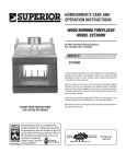
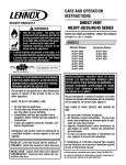
INSTALLATION AND OPERATION INSTRUCTIONS UNIVERSAL VENT-FREE FIREBOX 36" x 24" Universal Vent-Free Fireboxes P/N 506009-07 REV. A 05/2013 MODEL EWVF36 INSTALLER: Leave this manual with the appliance. CONSUMER: Retain this manual for future reference. In the Commonwealth of Massachusetts: • Installation must be performed by a licensed plumber or gas fitter; • See Table of Contents for location of additional Commonwealth of Massachusetts requirements. WARNING: If the information in this manual is not followed exactly, a fire or explosion may result causing property damage, personal injury or loss of life. FOR YOUR SAFETY: Do not store or use gasoline or other flammables or liquids in the vicinity of this or any other appliance. FOR YOUR SAFETY: What to do if you smell gas: • DO NOT light any appliance. • DO NOT touch any electrical switches. • Do not use any phone in your building. • Immediately call your gas supplier from a neighbor’s phone. Follow your gas suppliers instructions. • If your gas supplier cannot be reached, call the fire department. Installation and service must be performed by a qualified installer, service agency or the gas supplier. For use only with A LISTED GAS-FIRED UNVENTED DECORATIVE ROOM HEATER NOT TO EXCEED 40,000 BTU/H. Do not BUILD A WOOD FIRE. Warning: Improper installation, adjustment, alteration, service or maintenance can cause injury or property damage. Refer to this manual. For assistance or additional information consult a qualified installer, service agency or the gas supplier. Carefully review the instructions supplied with the decorative type unvented room heater for the minimum fireplace size requirement. Do not install AN appliance in this firebox unless this firebox meets the minimum dimensions required for the installations. THIS IS A VENT-FREE GAS-FIRED HEATER ENCLOSURE. IT USES AIR (OXYGEN) FROM THE ROOM IN WHICH IT IS INSTALLED. PROVISIONS FOR ADEQUATE COMBUSTION AND VENTILATION AIR MUST BE PROVIDED. REFER TO COMBUSTION AND VENTILATION AIR SECTION, PAGE 4. Due to high temperatures, the appliance should be located out of traffic and away from furniture or draperies. Do not place clothing or other materials on or near this appliance. Portland US OTL Report No.116-F-38c-5 Important: read and understand these instructions completely before installing your Vent-Free room heaters. Important safety information Installer: Please leave these instructions with the owner. Owner: Please retain these instructionS for future reference. WARNING If the information in this manual is not follwed exactly, a fire or explosion may result causing property damage, personal injury or loss of life. IMPORTANT The fireplace screens on the appliance must be closed prior to operating the fireplace. WARNING These built-in vent-free fireboxes have only been tested and approved for use with ANSI Z21.11.2 Ventfree gas logs. WARNING Do not attempt to burn solid wood fuels, other gas log sets or any other combustible materials in this vent-free firebox. WARNING Any change to this Vent-Free room heater can be dangerous. Improper installation or use of this heater can cause serious injury or death from fire, burns, explosion or carbon monoxide poisoning. WARNING Do not allow fans to blow directly into the fireplace. Avoid any drafts that alter burner flame patterns. 2 WARNING Carbon Monoxide Poisoning: Early signs of carbon monoxide poisoning are similar to the flu with headaches, dizziness and/or nausea. If you have these signs, obtain fresh air immediately. Have the Vent-Free Gas Heater serviced as it may not be operating correctly. WARNINGS • Due to high temperatures, the firebox should be located out of traffic and away from furniture and draperies. • Do not place clothing or other flammable material on or near the heater. • Any safety screen or guard removed for servicing the firebox must be replaced and/or closed prior to operating the heater. • Installation and repair should be done by a qualified service person. The heater should be inspected before use and at least annually by a professional service person. More frequent cleaning may be required due to excessive lint from carpeting, bedding material, etc. It is important that control compartments, burners and circulating air passageways of the heater be kept clean. • Allow the heater to cool before servicing. Always shut off any electricity or gas to the heater while performing service work. • Do not install the firebox in a sleeping room or bathroom. • The appliance and its individual shut-off valve must be disconnected from the gas supply piping system while performing any tests of the gas supply piping system at test pressures equal to or less than 1/2 psig. WARNING • The heater must be isolated from the gas supply piping system by closing its individual manual shut-off valve during any pressure testing of the gas supply piping system at test pressures equal to or less than 1/2 psig. • Keep heater area clear and free from combustible materials, gasoline and other flammable vapors and liquids. • Do not use this heater if any part has been under water. Immediately call a qualified service technician to inspect the heater and to replace any part of the control system and any gas control which has been under water. • Ensure that the heater is clean when operating. Excessive dust accumulation on the burner and logs will increase the amount of carbon monoxide formation and could lead to carbon monoxide poisoning and death. IMPORTANT Before starting your firebox installation, read these installation instructions carefully to be sure you understand them completely and in entirety. Failure to follow these instructions could cause a heater malfunction resulting in serious injury and/or property damage. WARNING Do not install in the vicinity where gasoline or other flammable liquids may be stored. The Vent-Free firebox must be kept clear and free from these combustible materials. WARNING Maintain minimum clearances. Congratulations! Misc. Codes / Standards In selecting this Everwarm Vent-Free Gas Firebox you have chosen the finest and most dependable fireplace to be found anywhere. A beautiful, prestigious, alternative to a wood burning fireplace. Welcome to a family of Everwarm Fireplace Owners. The Installation must conform to local codes or, in the absence of local codes, with the National Fuel Gas Code, ANSI Z223.1/NFPA 54 - latest edition. Please read and carefully follow all of the instructions found in this manual. Please pay special attention to the safety instructions provided in this manual. The Homeowner's Care and Operation Instructions included here will assure that you have many years of dependable and enjoyable service from your Everwarm product. Table of contents General Information Important Safety Information............ Page2 Packaging List................................... Page3 General Information.......................... Page3 Burn-in Period................................... Page3 Tools/Building Supplies..................... Page3 Codes................................................ Page3 Combustion And Ventilation Air........ Page4 Cold Climate Insulation..................... Page4 Requirements for the Commonwealth of Massachusetts. Page5 Location Of Firebox........................... Page 6 Clearances........................................ Page 6 Assembly Steps................................ Page8 Gas Line Installation.......................... Page8 Firebox Framing................................ Page 9 Firebox Installation............................ Page 9 Specifications.................................... Page10 Framing Specifications...................... Page11 Hood Installation............................... Page11 Optional Equipment / Blower Kit Installation................................... Page12 Firebox Finishes................................ Page15 Accessories/components.................. Page15 Replacement Parts List..................... Page17 These Vent-Free firebox enclosures are designed to accept all ANSI Z21.11.2 approved Decorative Type Vent-Free Gas Log Room Heaters. For the appropriate Vent-Free Gas Log Room Heater model, refer to Page 16 (see Vent-Free Gas Log Sets). Refer to the installation instructions provided with the log sets for detailed instructions. This installation manual will help you obtain a safe, efficient, dependable installation for your appliance and vent system. PLEASE READ AND UNDERSTAND THESE INSTRUCTIONS BEFORE BEGINNING YOUR INSTALLATION. Packaging List Vent-Free Gas Firebox Hood Installation and Operation Instructions Warranty Certificate This installation manual along with the vent-free gas log installation manual will enable you to obtain a safe, efficient and dependable installation of your room heater system. Do not alter or modify the firebox or its components under any circumstances. Any modification or alteration of the firebox system, including but not limited to the firebox and accessories, may void the warranty, listings and approvals of this system and could result in an unsafe and potentially dangerous installation. These Built-In Vent-Free Fireboxes have been tested and approved as Ventless Firebox Enclosures for Gas-Fired Unvented Decorative Room Heaters to ANSI Z21.91-2007. Burn-in Period During the first few times of operation of this appliance there will be some odor due to the curing of the paint and burning off of lubricants used in the manufacturing process. We recommend that you open windows and ventilate the house during the initial burns. The paint emits non-toxic odors during this process. Depending on your use, the burn-in period may take a few hours or a few days. The appliance, when installed, must be electrically grounded in accordance with local codes or, in the absence of local codes, with the National Electrical Code, ANSI/NFPA 70 - latest edition. Check the packaging list to be sure that you have all the necessary parts in usable condition. Also check for concealed damage. Tools and Building Supplies Normally Required Tools Should Include: • Phillips screwdriver • Hammer • Saw and/or sabersaw • Level • Measuring tape • Electric drill and bits • Pliers • Square • Piping complying with local codes • Pipe wrench • Tee joint • Pipe compound Building Supplies Should Include: • Framing materials • Wall finishing materials • Caulking materials (noncombustible) • Fireplace surround materials (noncombustible) • Insulation (for packing around gas-line penetration holes) Codes Adhere to all local codes or in their absence the latest edition of The National Fuel Gas Code ANSI Z223.1 or NFPA 54 - latest edition which can be obtained from The American National Standards Institute, Inc. (1430 Broadway, New York, NY, 10018) or National Fire Protection Association, Inc. (Batterymarch Park, Quincy, MA, 02269). KEEP YOUR HOUSE WELL VENTILATED DURING THE BURN-IN PERIOD. THE ODOR AND HAZE EMITTED DURING THE BURN-IN PERIOD CAN BE QUITE NOTICEABLE AND MAY SET OFF A SMOKE DETECTOR. If an optional blower is installed, Do not turn it on during the Burn-In period. 3 Combustion and Ventilation Air Heaters installed in these appliances shall not be installed in a confined space. Heaters installed in these appliances may be located in unusually tight construction provided the space is unconfined, or if confined, is provided with two permanent openings communicating directly with an additional room(s) of sufficient volume so that the combined volume of all connected spaces meets the criteria for an unconfined space, (National Fuel Gas Code ANSI Z223.1/NFPA 54 - latest edition, Section on Air for Combustion and Ventilation). Generally 50 ft 3 per 1,000 BTU input of all operating appliances in the space. The National Fuel Gas Code defines a confined space as a space whose volume is less than 50 ft 3 per 1,000 BTU/Hr (4.8 m3 per kw) of the aggregate input rating of all appliances installed in that space and an unconfined space as a space whose volume is not less than 50 ft 3 per 1,000 BTU/Hr (4.8 m3 per kw) of the aggregate input rating of all appliances installed in that space. Rooms communicating directly with the space in which the appliances are installed, through openings not furnished with doors, are considered a part of the unconfined space. Unusually tight construction is defined as construction where: a. Walls and ceilings exposed to the outside atmosphere have a continuous water vapor retarder with a rating of one perm or less with openings gasketed or sealed, and b. Weather stripping has been added on operable windows and doors, and c. Caulking or sealants are applied to areas such as joints around window and door frames, between sole plates and floors, between wall-ceiling joints, between wall panels, at penetrations for plumbing, electrical, and gas lines, and at other openings. Use the following equations to determine if you have a confined or unconfined space. 1.Determine the volume of space — ft 3. Length x Width x Height =______ ft 3 (Include adjoining rooms with doorless passageways or ventilation grills between rooms). Example: 24' (L) x 16' (W) x 8' (H) = 3072 ft 3 2.Divide the volume of space by 50 ft 3 to determine the maximum BTU/Hr the space can support. _(volume of space – ft 3)/ 50 ft 3 = (Maximum BTU/Hr the space can support) Example: 3072 ft 3 / 50 ft 3 = 61.44 or 61,440 BTU/Hr the space can support. 3.Add the BTU/Hr of all the fuel burning appliances in the space. Vent-Free heater Gas appliance #1* Gas appliance #2 ________ BTU/Hr ________ BTU/Hr +________ BTU/Hr Total =________ BTU/Hr Example: Vent-free heater 26,000 Gas appliance #1 40,000 (water heater) Total = 66,000 BTU/Hr BTU/Hr BTU/Hr * Do not include direct-vent gas appliances. Direct-vent is sealed combustion and draws combustion air from the outdoors. 4.Compare the maximum BTU/Hr the space can support with the actual amount of BTU/Hr used. __________ BTU/Hr (max. the space can support) __________ BTU/Hr (actual amount of BTU/Hr used) Example: 61,440 BTU/Hr (max. the space can support) 66,000 BTU/Hr (actual amount of BTU/Hr used) The space in the above example is a confined space because the actual BTU/Hr used is more than the maximum BTU/Hr the space can support. You must provide additional fresh air. WARNING If the area in which the heater may be operated does not meet the required volume for indoor combustion air, combustion and ventilation air shall be provided by one of the methods described in the National Fuel Gas Code, ANSI Z223.1/NFPA 54, the International Fuel Gas Code, or applicable local codes. 4 Note: Diagrams & illustration ARE not to scale. Your options are: a.Rework equations adding the space of adjoining room(s). If the extra volume provides an unconfined space, then remove door or add ventilation grills between rooms. Refer to National Fuel Gas Code, ANSI Z223.1 - latest edition, Section on Air for Combustion and Ventilation. b.Vent room directly to the outdoors. Refer to National Fuel Gas Code, ANSI Z223.1 - latest edition, Section on Air for Combustion and Ventilation. c.Install a lower BTU/Hr heater, such as a 21,000 BTU/Hr, to make the area an unconfined space. If the actual BTU/Hr used is less than the maximum BTU/Hr the space can support, then the space is an unconfined space. You will need no additional fresh air ventilation for an unconfined space. This appliance shall not be installed in a room or space unless the required volume of indoor combustion air is provided by the method described in the National Fuel Gas Code, ANSI Z223.1/NFPA 54, the International Fuel Gas Code, or applicable local codes. Maintain adequate clearances around air openings. Maintain adequate clearances for accessibility for purposes of servicing and proper operation. Cold Climate Insulation For cold climate installations, seal all cracks around the appliance with noncombustible material and wherever cold air could enter the room. It is especially important to insulate outside cavities between studs and under floor on which the appliance rests, if floor is above ground level. Gas line holes and other openings should be caulked with high temperature caulk or stuffed with unfaced fiberglass insulation. If the fireplace is being installed on a cement slab, in cold climates, a sheet of plywood or other raised platform can be placed underneath to prevent conducting cold up into the room. It also helps to sheetrock inside surfaces and tape for maximum air tightness and caulk firestops. (e)Unvented propane or natural gas-fired space/room heaters shall be prohibited in bedrooms and bathrooms. NOTE: The following requirements reference various Massachusetts and national codes not contained in this document. (f)Space/room heaters shall be properly sized for the room or space of installation, but shall not exceed a maximum of 40,000 BTU input per room or space. Requirements for the Commonwealth of Massachusetts Un-vented Room Heaters shall be installed in accordance with 527 CMR 30.00 and 248 CMR 3.00 through 7.00: (g)In occupancies with an unvented propane or natural gas-fired space/room heater, no less than one listed carbon monoxide detector that is installed in accordance with the manufacturers instructions shall be installed and maintained near the space where the heater is located. (a) Permits and Inspections: In addition to complying with 248 CMR 3.05 the following requirements must be satisfied: 1. A permit shall be obtained from the head of the fire department and the local or state gas inspector having jurisdiction for the installation of all unvented propane or natural gas-fired space/room heaters. 1. Any building wherein the heater is to be installed shall, as a precondition to such installation, have working smoke detectors installed and maintained in accordance with the requirements of 780 CMR (State Board of Building Regulations and Standards) in effect at the time of construction or; 2. If no requirement was in effect at the time of construction the smoke detector shall be compliant and installed as provided for in M.G.L. c. 148, § 26E. 2. The permits shall be conditioned upon final inspection and approval of installation by the head of the fire department and the local or state gas inspector having jurisdiction. 3. A copy of the manufacturer’s installation/operating literature shall be submitted with each permit application. 4. Before operation, the Head of the Fire Department and the local or state gas inspector shall inspect the installation for compliance with 527 CMR (Board of Fire Prevention Regulations) and 248 CMR (Board of State Examiners of Plumbers and Gas Fitters). 5. A final inspection by the state or local gas inspector of the unvented space/room heater shall not be performed until proof is provided that the head of the fire department having jurisdiction has granted a permit. (b)Unvented propane or natural gas-fired space/room heaters shall conform to ANSI Z21.11.2, be equipped with an oxygen depletion safety (ODS) shutoff system and be Product-approved in accordance with 248 CMR. (c)Unvented propane or natural gas-fired space/room heaters shall be installed in accordance with their listings and the manufacturer’s instructions. Proper clearances to combustibles shall be maintained. In no case shall the clearances be such as to interfere with combustion air and accessibility. (h)In rooms and buildings served by an unvented propane or natural gas-fired space/room heater, a primary source of heat, which is operable, shall be permanently installed and maintained in the building in accordance with 105 CMR (Department of Public Health). (i)Sellers of unvented propane or natural gas-fired space/room heaters shall provide to each purchaser a copy of 527 CMR 30.00 upon sale of the unit. • Installation and repair must be done by a plumber or gas fitter licensed in the Commonwealth of Massachusetts. • The flexible gas line connector used shall not exceed 36 inches (92 centimeters) in length. • The individual manual shut-off must be a T-handle type valve. (d)Installations shall be of a permanent type, with a permanently piped fuel supply in accordance with 248 CMR. LPG appliances shall be subject to the storage requirements in accordance with 527 CMR 6.00. Portable unvented propane or natural gas-fired space/room heaters shall be prohibited. 5 Note: Diagrams & illustration ARE not to scale. Location of firebox Carefully select the best location for installation of your built-in Vent-Free firebox. The following factors should be taken into consideration: • Clearance to side wall, ceiling, woodwork and windows. • Location must not be affected by drafts caused by kitchen exhaust fans, return air registers for forced air furnaces/air conditioners, windows or doors. • Installation must provide adequate ventilation and combustion air. • Do not install this firebox in a sleeping room or bathroom. WARNING Do not install these built-in VentFree fireboxes in sleeping quarters, or in recreational vehicles. WARNINGS Do not install these appliances: • Where curtains, furniture, clothing or other flammable objects are less than 42" from the front of the Vent-Free room heater. • In high traffic areas. • In windy or drafty areas. • Location should be out of high traffic areas and away from furniture and draperies due to heat from firebox. 16" Do Optional Hearth Extension Figure 2 Ceiling clearance: The ceiling must be at least 40" from the top of the firebox opening (Figure 2 ). Noncombustible material: Noncombustible materials, such as slate and marble, must be at least 1/2" thick and may be used without restriction above the firebox opening, to the sides or as a hearth extension, so long as they do not obstruct vent openings for heat circulating models. • Never obstruct the front opening of the Vent-Free firebox or restrict the flow of combustion and ventilation air. • Minimize modifications to existing construction. See Figure 1 for location suggestions. RECOMMENDATION: Use high temperature finish material for the mantels. CAUTION Do not install in the vicinity where gasoline or other flammable liquids may be stored. The Vent-Free firebox must be kept clear and free from these combustible materials. 40" Not to Scale Figure 1 Combustible Wall Clearance Above Appliance (all models) Finished Wall Clearances WARNING Do not use a blower insert, heat exchanger insert or other accessory not approved for use with this appliance. Ensure the minimum clearances shown in Figures 2 through 4 are maintained. Left and right clearances are determined when facing the front of the firebox. Follow these instructions carefully to ensure safe installation. Failure to follow these requirements may create a fire hazard. Sidewall clearances: The sides of the firebox opening must be at least 16" from any combustible wall (Figure 2). Non-Combustible Material 3" Min. (shaded area) Shown with hood Installed (required on EWVF36) Note: Diagrams & illustration ARE not to scale. Top of Appliance Fireplace Opening Figure 3 6 Header Top StandOff Spacer (on appliance) Combustible Mantel and Trim Clearance Model EWVF36 WITH Hood Installed Hood is required on all installations for this model. Noncombustible material (minimum requirements) with wood mantel or other combustible projections: To install the firebox with a wood mantel, shelf or other combustible projection above firebox opening. Refer to Figure 4. Minimum clearance requirements include any projections such as shelves, window sills, mantels, etc. above the appliance. Safe Zone Combustible Mantel and Trim WARNING 18” 17” 16” 15” Coordinate in ()Example 14” Combustible Material (wall) 13” Example 12” 11” Header 10” Top Spacer on Appliance 9” 8” 7“ 6” 5” 4” Non-Combustible Material 3” Min. 3” Top of Appliance Example Top of Firebox Opening Hood Screen sEXAMPLE: If you choose to install a mantel that projects 5", you will need to install it so that the bottom of the mantel and trim is approximately 13" or more above Firebox opening (see coordinate in shaded area above). Figure 4 The hood must be in place to be in compliance with the clearances specified in Figure 4. Do not remove or replace hood, only use hood supplied for these fireboxes (see Page 17). Do not use any hood which may be provided with the decorative type Vent-Free room heater. If your mantel profile is unsafe, you may either: • Raise the mantel to an acceptable height, or • Remove the mantel. Floor clearance: These fireplaces may sit directly on a combustible surface. The appliance should be mounted on a fully supported base extending the full width and depth of the unit. The appliance may be located on or near conventional construction materials. However, if installed on combustible materials, such as carpeting, vinyl tile, etc., a metal or wood barrier covering the entire bottom surface must be used. 7 Note: Diagrams & illustration ARE not to scale. Assembly Steps Consult all local codes. NOTES: • Illustrations shown in this manual reflect “typical” installations with nominal dimensions and are for design and framing reference only. Actual installations may vary due to individual design preferences. However, always maintain minimum clearances to combustible materials and do not violate any specific installation requirements. Refer to the Framing Specifications Figures on Page 11. Properly size and route the gas supply line from the supply regulator to the area where the appliance is to be installed per requirements outlined in the National Fuel Gas Code, NFPA 54 - latest edition (USA) or B149 - latest edition (Canada). Never use galvanized or plastic pipe. Gas lines must be routed, constructed and made of materials that are in strict accordance with local codes and regulations. We recommend that a qualified individual such as a plumber or gas fitter be hired to correctly size and route the gas supply line to the appliance. Installing a gas supply line from the fuel supply to the appliance involves numerous considerations of materials, protection, sizing, locations, controls, pressure, sediment, and more. Certainly no one unfamiliar and unqualified should attempt sizing or installing gas piping. • The following steps represent the normal sequence of installation. Each installation is unique, however, and might require a different sequence. Step 1. Position firebox prior to framing or into prepared framing. Step 2. Field wire the main power supply to the appliance if a blower kit is to be installed (at the time of installation or a later date). An optional junction box kit and blower kit is required (see Page 16 for ordering information). Follow the installation and wiring instructions on Pages 12 through 14). Electrical connections should only be performed by an experienced, licensed/certified tradesman. Step 3. Plumb gas line. (Gas connections should only be performed by an experienced, licensed/ certified tradesman). Step 4. Install decorative type Vent-Free room heater per the instructions provided with the Vent-Free room heater. Step 5. Complete finish wall material, surround and optional hearth extension to your individual taste. Installation Gas Line Installation CAUTION Plumbing connections should only be performed by a qualified, licensed plumber. Main gas supply must be off when plumbing gas line to fireplace or performing service. Remove the gas line access cover plate on either the left or right side of the fireplace (see Figure 6 showing locations). Install 1/2" min. to 1-1/2" max. inside diameter approved gas line through the firebox wall for connection to the Vent-Free room heater inside the firebox. Connect the gas line before the firebox is enclosed in the finished wall. Gas line holes and other openings should be caulked with high temperature caulk or stuffed with unfaced fiberglass insulation. Ensure that a sediment trap is installed in the existing gas line, if not, install a sediment trap upstream of the heater to prevent moisture and contaminants from passing through trap to the heater controls and burners. Failure to do so could prevent the heater from operating reliably. An external regulator must be used on all propane (L.P.G). heaters, in addition to the regulator fitted to the heater, to reduce the supply tank pressure to 13" W.C. (maximum). Any copper tubing used to supply propane (L.P.G). from the tank must be internally tinned. WARNING Check Gas Type: The gas supply must be the same as stated on the heater’s rating plate. If the gas supply is different, DO NOT INSTALL the heater. Contact your dealer for the correct model. 8 Note: Diagrams & illustration ARE not to scale. IMPORTANT Hold heater regulator with a wrench to prevent movement when connecting to inlet piping. WARNING Connecting directly to an unregulated propane (L.P.G.) tank can cause an explosion. IMPORTANT Pack unfaced fiberglass insulation material (not provided) around the gas line access hole on appliance and all exterior gas line penetration holes. TEST ALL CONNECTIONS FOR GAS LEAKS (FACTORY AND FIELD) Test all gas joints from the gas meter to the gas heater regulator for leaks using a gas leak test solution (also referred to as bubble leak solution). NOTE: Using a soapy water solution as a leak detection solution is not recommended because the soap residue that is left on the pipes/fittings can result in a false-positive leak detection reading if a gas leak sniffer is used. Soap residue can also result in corrosion over time. DO NOT USE AN OPEN FLAME TO CHECK FOR LEAKS. Leak Test Procedure: Turn on gas supply and test for gas leaks using a gas leak test solution. A.Light the appliance (refer to the lighting instructions label provided with gas logs). B. Brush all joints and connections with the gas leak detection solution. If bubbles are formed, or gas odor is detected, turn the gas control knob (off/pilot/on) to the “OFF” position. Either tighten or refasten the leaking connection, then retest as described above. C.When the gas lines are tested and found to be leak free, rinse off the leak testing solution from gas line fittings. Firebox Framing Construct firebox framing following Figures 7 through 9 and Table 1 on Page 11 for your specific installation requirements. Refer to Figure 6 on Page 10 for firebox dimensions. The firebox may be installed directly on a combustible floor or raised on a platform of an appropriate height. When the appliance is installed directly on carpeting, vinyl tile or other combustible material, other than wood flooring, the appliance shall be installed on a metal or wood panel extending the full width and depth of the appliance. Be sure firebox rests on a solid continuous floor or platform with appropriate framing for support and so that no cold air can enter room from under the firebox. CAUTION Do not block the heat-circulating air inlets and outlets on these fireboxes. Doing so may create a potential fire hazard. The firebox may be positioned and then the framing built around it, or the framing may be constructed and the firebox positioned into the opening. Usually, no special floor support is needed for the firebox, however, to be certain: 1.Estimate the total weight of the firebox system and surround materials such as marble, brick, stone, etc., to be installed (see Product Referance Table on Page 10 for appliance weight). 2.Measure the square footage of the floor space to be occupied by the system and surrounds. 3.Note the floor construction, i.e. 2" x 6", 2" x 8" or 2" x 10", single or double joists, type and thickness of floor boards. NOTE: The nailing flange and the area directly behind the nailing flange is exempt from the clearances described on the firebox clearance label. 4.Use this information and consult your local building code to determine if you need additional support. Step 4. To safely operate the heater with consideration of the mantel clearances the hood must be installed. If you plan to raise the firebox, build the platform assembly then position firebox on top. Secure the platform to the floor to prevent possible shifting. Firebox Installation Step 1. Frame these appliances as illustrated in Figures 7 through 9. All framing details must allow for a minimum clearance to combustible framing members as shown in Figures 2 through 4. Also refer to appliance specifications on Page 10 . Headers may be in direct contact with the appliance top spacers but must not be supported by them or notched to fit around them. All construction above the appliance must be self supporting, DO NOT USE THE APPLIANCE FOR STRUCTURAL SUPPORT. IMPORTANT Under no circumstances shall the firebox top spacers be removed or modified (see Figure 5). The header may be in direct contact with the top spacers but must not be supported by them, notched or altered to fit around them. Top Spacer NOTE: The framed depth from a framed wall, must always be measured from a finished surface. If a wall covering such as drywall is to be attached to the rear wall, then the depth must be measured from the drywall surface. It is important that this dimension be exact. 8d Nail Step 2. Level the firebox by checking the top edge of the firebox. Shim if necessary. Step 3. Fireplace should be secured to side framing members using the full length nailing tabs at the top and bottom of the fireplace front face. Use 8d nails (see Figure 5). Figure 5 9 Note: Diagrams & illustration ARE not to scale. Specifications Dimensions - Inches (millimeters) Model No. A B C D E F G H J K L M N P *Q EWVF36 36 (914) 24 (610) 41-3/4 (1061) 37-1/4 (946) 23-1/2 (597) 20 (508) 3 (76) 7-3/8 (187) 15-7/8 (403) 7-1/2 (190) 11-15/16 (303) 1-5/16 (33) 5-1/2 (140) 30-5/16 (770) 29-5/8 (753) Product Reference Information Model Ship. Weight (lbs) Shipping Volume EWVF36 150 lbs 20 Cu. Ft. * A hood comes standard and is required for model EWVF36. The factorysupplied hood must be installed on the firebox for safe operation in all installations. E Junction Box F N Top View M Top Stand-Off Spacers (4 places) 1 (25) 7-1/16 (179) Top of Firebox Opening 3-9/16 (90) G * Hood B Gas Line Access Both Sides D Bottom of Firebox Opening Top of Bottom Refractory 6-3/16 (157) P *Q J 5-3/4 (146) H K L A C Right Side View Front View Figure 6 10 Note: Diagrams & illustration ARE not to scale. Access Opening for Junction Box - Right Side Only (remove the knock-out before installing J-Box). J-Box / Electrical Kit is not provided with appliance. Framing Specifications Corner Installation Framing Dimensions Back Wall Of Chase/Enclosure Including Finishing Materials If Any This Figure corresponds to Table 1 Opening EWVF36 A 42-1/4" (1073) B 40-1/4" (1022) C 23-9/16" (599) D 11-1/4" (286) E 63-1/2" (1613) F 31-3/4" (807) G 20-1/2"( 521) H 44-3/16" (1122) D F H G C A E Table 1 - This Table corresponds to Figures 7, 8 and 9 Rough Framing Face (Unfinished Shown) Figure 8 Parallel Installation Rough Framing Face (Unfinished Shown) WARNING: Do not fill spaces around the firebox with insulation or other materials. Back Wall Of Chase/Enclosure Including Finishing Materials If Any C Header This Figure corresponds to Table 1 G B A Figure 7 A Figure 9 This Figure corresponds to Table 1 Hood Kit Installation The firebox canopy (hood) must not be modified or replaced with a canopy that may be provided with the unvented decorative room heater. NOTE: A hood comes standard and is required for model EWVF36. The factory-supplied hood must be installed on the firebox for safe operation for model EWVF36 in all installations. See Figure 11. These hood kits are design to be fitted to the face of the appliance directly above the firebox opening. In addition to providing an aesthetically pleasing appearance to your appliance, the hood reduces heat effects to decorative mantels and finish materials located directly above the fireplace and reduces the Mantel / Trim clearances (see Figure 4 on Page 7). Removing Screens and Rods: Remove screws (see dotted lines). Pull out rods from locating holes on side of firebox opening. Reinstalling Screens and Rods: Insert rods into corresponding locating holes on sides of firebox opening, then reinstall screws as shown. Please read this entire manual and understood thoroughly before proceeding with the installation of these kits. Step 1. Using a 5/16" nut driver or socket, remove the screen and rod assemblies as shown in Figure 10. Step 2. Align the hood with the holes in the side frames as shown in Figure 11. Install three screws as shown in Figure 11. Make sure hood is level and secure. Step 3. Reinstall screen and rod assemblies (see Figure 10). Figure 10 Note: Diagrams & illustration ARE not to scale. 11 IMPORTANT Figure 11 Optional Equipment Blower Kits The EWFBK100 Blower Kits are used when a wall-mounted ON/OFF blower switch is desired, and the EWFBK200 Blower Kits are used when a wall-mounted variable speed blower control (rheostat) is desired. A Junction Box / Electrical Kit is also required to install these kits (purchased separately - see Page 16). Bend blower mounting tabs up to secure Tie a loose knot in power blower in place cord to take up slack * The Junction Box / Electrical Kit is not included. See Page 16 for ordering information. Figure 13 120V, 60HZ, 1PH BLOWER CONTROL CIRCUIT WIRING CAUTION Electrical connections should only be performed by a qualified, licensed electrician. Main power must be off when connecting to main electrical power supply or performing service. * Wall-mounted ON/ OFF Blower Switch or Variable Speed Control Switch. HOT SIDE OF RECEPTACLE Black The blower is installed beneath the firebox. Room air is drawn in through the side slots of the fireplace, heated as it passes across the firebox, and discharged through the upper area of the firebox opening. Blower Motor NEUTRAL SIDE OF RECEPTACLE Grounded to Appliance The installation instructions for installing these blower kits are on Pages 12 through 14. Also see the installation instructions provided with the blower kits (Form # 506020-27). For electrical requirements, refer to Figures 12, 13 and 14. If the blower kit is to be installed at the time of installation or at a later date, the main power supply must be installed at the time of installation. This will require that the electrical connections must be made BEFORE the firebox is framed and enclosed in the finished walls. Route a 3-wire, 120 VAC, 60 Hz, 1 ph power supply and connect to electrical receptacle wires and wall switch or rheostat. Blower 120 VAC Black Side View The appliance must be electrically grounded in accordance with local codes or, in the absence of local codes, the national electrical code, ANSI/NFPA 70-(latest edition). (In Canada, the current CSA C22.1 Canadian Electrical Code). * Junction Box * Electrical Outlet Ground - Green Neutral - White Hood The Ground Lead must be connected to the green screw (located on the junction box). Failure to do this could result in an electrical short or shock injury. Top View Tab Intact Junction Box Plug blower into this receptacle Motor Plug Green Ground Screw Field Wired Factory Wired Blower Receptacle Ground 120V Appliance Junction Box NOTE:If Ifany anyofofthe theoriginal originalwire wireasassupplied suppliedmust NOTE: must be replaced, be replaced be replaced, it mustit must be replaced with with type type AWM AWM 105°cC -– 14 18Ga. 105 degree gagewire wire. Figure 12 *A ON/OFF Wall Switch is used with the EWFBK100 kit (field provided; A Variable Speed Control (provided) is used with the EWFBK200 kit. The installation of these kits also require a Junction Box / Electrical Kit, not included. See Page 16 for ordering information. NOTE: If any of the original wire as supplied must be replaced, it must be replaced with type AWM 105 degree C - 14 gage wire. Figure 14 12 Note: Diagrams & illustration ARE not to scale. Installation Instructions - EWFBK100 or EWFBK200 Blower Kits and EWJBK Junction Box Kit Cover Plate J-Box and Receptacle IMPORTANT All electrical wiring must be performed by licensed Electricians. Electrical wiring must comply with the National Electrical Code ANSI/ NFPA 70 - latest edition Step 1. Follow the instructions below for the model you are installing: Remove knock-out (strain relief bushing presses into this hole around romex wires - see Step 8 on Page 14). Screw Model EWVF36: Using a screwdriver remove the screw from the blower access panel as shown in Figure 15. Slide the panel to the right until the flange clears the opening. Remove the panel and set aside. Step 2. Remove the rectangular knock-out (for J-Box) on the right side of unit (see Figure 6 for location). Install the Junction Box and Electrical outlet below the firebox floor into the rectangular opening on the right side cabinet panel where you removed the knock-out (see Figures 17 and 18). The Junction Box / Electrical Kit is sold separately (see Page 16 for ordering information). Strain Relief Bushing Figure 16 - Junction Box Kit J-Box and Electrical Outlet J-Box Flange Firebox floor NOTE: Pass the wires through the hole, then squeeze the J-Box flanges together to fit into opening. Step 3. Loosely tie a knot in the power cord to take up slack (see Figure 19). Step 4. Locate the tabs shown in Figure 20. Position the blower assembly so that the tabs (located on the cabinet base) are seated in the notches of the blower bracket. Bend the tabs over to secure the blower assembly (see Figure 21). Install into side wall rectanular opening Figure 17 J-Box Flanges Right Outside Cabinet Panel Step 5. Plug power cord into the electrical outlet as illustrated in Figure 13. Firebox floor Screw J-Box and Electrical Outlet Blower Access Panel Wires Remove screw, then lift out blower access panel. Figure 15 - Model EWVF36 Figure 18 13 Note: Diagrams & illustration ARE not to scale. Step 8. Ensure that power supply wires are NOT "live" before making these connections). Install J-Box Cover Plate as follows: Feed the * Romex wires (or other equivalent plastic insulated wire - Refer ANSI/NFPA 70 - National Electrical Code - Latest Edition) through the J-Box Cover retangular opening, then connect to the J-box wires. The strain relief bushing should be pressed into the knock-out on J-box cover around the Romex (this will provide protection to the wires and prevents strain against connections from J-box). See Wiring Diagram - Figure 14. Install the cover plate over J-Box opening on appliance as shown in Figure 22. Firebox floor NOTE: Wire connections should be positioned inside of the appliance. Loose knot in power cord to take up slack * Romex is a plastic insulated wire from power supply - sometimes called non-metallic sheath. Figure 19 Right Side Panel of Firebox Cabinet Base J-Box opening on appliance Locating Tabs Use screw provided and secure in place as shown Figure 20 Screw The notched side of cover plates goes inside firebox panel Cover Plate Figure 22 - Installing J-box Cover Plate - All Models Step 9. Follow the instructions below for the kit you are installing: EWFBK100 Kits - Install a locally sourced ON/OFF wall switch in a convenient location on a wall, near the fireplace. Bend Locating Tabs Over (into notches) Figure 21 EWFBK200 Kits - Install the kit-provided variable speed control (rheostat) in a convenient location on a wall, near the fireplace. Step 6. Route a 3-wire, 120 VAC, 60 Hz, 1 ph power supply to the right side of appliance. Step 7. Locate the J-Box cover (provided in J-Box Kit). Remove the round knock-out (see Figure 16). Step 10. Follow the instructions below for the model you are installing: Model EWVF36: Reinstall the blower access panel that was removed on Step 1 (see Figure 15). 14 Note: Diagrams & illustration ARE not to scale. Firebox finishes There are a wide variety of “finished looks” for your built-in Vent-Free firebox from formal wall decor with elaborate mantels to rustic wood paneling or warm brick facings. Only noncombustible materials like marble, stone, tile, brick, etc. may overlap the black front facing. Seal all joints between the black facing and wall surrounds to prevent air intrusion. Use noncombustible caulking material only to seal the black metal facing to the surround material on the finished wall. See Figures 3 and 23. Raised Hearth Extension A hearth extension may be used but is not required for these appliances. A raised hearth extension may be used as shown in Figure 23. Combustible Wall Non-Combustible Wall (see Figure 4) Fireplace Opening Raised Hearth Extension (combustibles allowed. No carpet or vinyl) Firebox Floor 5-3/4" Max.* * From Base to Bottom of Firebox Opening (floor) Combustible Platform Base SIDE VIEW Figure 23 - Raised Hearth Extension 15 Note: Diagrams & illustration ARE not to scale. APPROVED Accessories and components The variable speed control rheostat is included with EWFBK200 models only PA I N T Touch-Up Paint Kits Model No. Junction Box / Receptical Kit FTPK-B An locally sourced ON/OFF wall switch can be used with the EWFBK 100 models Model No. Description EWJBK Junction Box / Electrical Kit Junction Box / Receptical Kit The EWJBK Junction Box (J-Box) Kit is designed to be used when an optional EWFBK100 or EWFBK200 Blower Kit is to be installed. Touch-Up Paint (Black) (ref. Form # 750050M) Touch-Up Paint Kit * The installation of these kits also require a Junction Box / Receptical Kit, not included. See ordering information on this page. (ref. Form #506020-24) Description Repair of minor scratches and discoloration of the appliance black painted surfaces may be accomplished with the touch-up paint kit. * Forced Air Blower Kits Model No. Description EWFBK100 Blower, Standard (single speed) EWFBK200 Blower, Variable Speed (w/wall-mounted switch) (ref. Form # 506020-27) Blower Kit The EWFBK100 blower provides for a constant velocity forced air circulation feature for your appliance. The EWFBK200 assembly with variable speed wall switch provides a forced air circulation feature for your appliance. Outside Air Gate and Duct Kit Model No. Description EWOAKVF Outside Air Gate and Duct Kit (ref. Form #506020-25) Outside Air Gate and Duct Kit These kits have an air gate assembly, 4" diameter duct and a termination hood. The air gate allows adjustment of the amount of outside air delivered to the fire for combustion. Only one kit, located on the right side of the fireplace, is required. REMOTE CONTROL READY BURNER SYSTEM MODELS - Manufactured by CUI Part/Model Number Description BTU/hr Input Fuel Type EWPO2430NV Remote Control Ready Burner System 25,000/36,000 Natural Gas EWPO2430PV Remote Control Ready Burner System 25,000/36,000 Propane/LP Gas LOG SETS - Manufactured by CUI Part/Model Number 16 Description EWPO18R 18” Vent-Free Gas Log Set EWPO24R 24” Vent-Free Gas Log Set EWPO30R 30” Vent-Free Gas Log Set Note: Diagrams & illustration ARE not to scale. REPLACEMENT PARTS * NOTE: The model and serial number can be found on the rating label located on the bottom left front corner of the appliance. An exploded view of the firebox with numbered parts and a replacement parts list can be found on the page. Normally, all parts should be ordered through your distributor or dealer. Parts will be shipped at prevailing prices at time of order. If you encounter any problems or have any questions concerning the installation of a Vent-Free heater in this system, please contact your distributor or dealer or visit our website at www.cuiheat.com. When ordering repair parts, always give the following information: 1. The *model number of the firebox. 2. The *serial number of the firebox. 3. The part number. 4. The description of the part. 5. The quantity required. 3 6. The installation date of the firebox. WARNING Failure to position the parts in accordance with these diagrams or failure to use only parts specifically approved with this appliance may result in property 2damage or personal injury. 4 3 2 4 3 2 4 1 5 1 3 5 4 3 1 5 4 3 56 4 No.5 6 Description Gas Fireplace Assembly 6 EWVF36 Part No. Qty. - - 1. Firescreen H3814 2 2. 5 Rod, Screen H3815 2 3a. Refractory, Left H3809 1 3b. Refractory, Right H3810 1 4. Refractory, Rear H3811 1 5. Hood H1989 1 5 17 Note: Diagrams & illustration ARE not to scale. CUI reserves the right to make changes at any time, without notice, in design, materials, specifications, prices and also to discontinue colors, styles and products. Consult your local distributor for fireplace code information. Printed in U.S.A. © 2013 CUI 18 P/N 506009-07 REV. A 05/2013 CUI 1026 Old Stage Rd. Simpsonville, SC 29681