1
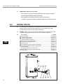
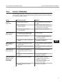
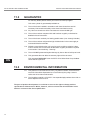
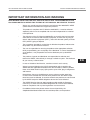
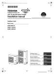
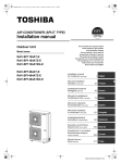
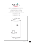
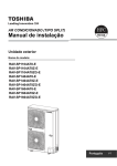
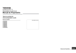
AIR TO WATER HEAT PUMP SYSTEM
Installation manual
HOT WATER CYLINDER
INDIRECT HEATING METHOD
CLOSED OUTLET (UNVENTED)
150 litre
210 litre
300 litre
HWS-1501CSHM3-E
HWS-2101CSHM3-E
HWS-3001CSHM3-E
AIR TO WATER HEAT PUMP SYSTEM
INSTALLATION AND SERVICE MANUAL
3
SYSTÈME DE POMPE À CHALEUR AIR-EAU
MANUEL D'INSTALLATION ET DE RÉPARATION
14
INSTALLATIONS - UND WARTUNGSANLEITUNG
26
SERVISNÍ A MONTÁŽNÍ MANUÁL
38
PRIRUČNIK ZA UGRADNJU I SERVISIRANJE
49
FELSZERELÉSI ÉS SZERVIZELÉSI KÉZIKÖN
60
ΕΓΧΕΙΡΙ∆ΙΟ ΕΓΚΑΤΑΣΤΑΣΗΣ ΚΑΙ ΣΥΝΤΗΡΗΣΗΣ
72
INSTALLATIONS- OCH SERVICEMANUAL
84
INSTALLASJONS- OG VEDLIKEHOLDSHÅNDBOK
95
LUFT-WASSER-WARMERPUMPENSYSTEM
SYSTÉM TEPELNÉHO ČERPADLA (VZDUCH - VODA)
SUSTAV S TOPLINSKOM CRPKOM ZRAK-VODA
LEVEGŐ-VÍZ HŐSZIVATTYÚ RENDSZER
ΣΥΣΤΗΜΑ ΑΝΤΛΙΑΣ ΘΕΡΜΑΝΣΗΣ ΑΕΡΑ - ΝΕΡΟΥ
LUFT/VATTEN-VÄRMEPUMPSSYSTEM
LUFT-TIL-VANN VARMEPUMPESYSTEM
SYSTÉM TEPELNÉHO ČERPADLA VZDUCH-VODA
NÁVOD NA INŠTALÁCIU A OBSLUHU
106
PRIROČNIK ZA MONTAŽO IN VZDRŽEVANJE
118
SISTEM TOPLOTNE ČRPALKE ZRAK–VODA
EN
FR
DE
CZ
CR
HU
GR
SV
NO
SK
SL
AIR TO WATER HEAT PUMP SYSTEM
INSTALLATION AND SERVICE MANUAL
AIR TO WATER HEAT PUMP SYSTEM
HOT WATER CYLINDER
INDIRECT HEATING METHOD
CLOSED OUTLET (UNVENTED)
INSTALLATION AND SERVICE MANUAL
IMPORTANT
PLEASE READ AND UNDERSTAND THESE INSTRUCTIONS BEFORE
INSTALLING THE WATER CYLINDER. INCORRECT INSTALLATION MAY
INVALIDATE GUARANTEE. THE WATER CYLINDER MUST BE INSTALLED
BY A QUALIFIED INSTALLER IN ACCORDANCE WITH LOCAL PLUMBING,
BUILDING AND ELECTRICAL REGULATIONS. PLEASE LEAVE THIS MANUAL
WITH THE UNIT FOR FUTURE REFERENCE.
TECHNICAL SPECIFICATIONS
Rated pressure
Test pressure (hydraulic)
Minimum recommended supply pressure
Max. primary circuit working pressure
Electrical rating (cylinder heater)
Weight (full)
150 litre indirect
210 litre indirect
300 litre indirect
EN
1.0 MPa (10 bar)
1.5 MPa (15 bar)
0.1 MPa (1 bar)
0.35 MPa (3.5 bar)
2.75kW @ 230V~
181 kg
251 kg
360 kg
COMPONENTS SUPPLIED
• Water cylinder incorporating electric cylinder heater and thermal controls.
• Safety Group incorporating a Pressure Relief Valve, Check (Non-return) Valve
and Isolating Valve.
• Compression nuts and olives.
• Cylinder heater key spanner.
3
France
Carrier S.A. Route de Thil
BP 49 01122 Montiuel
Cedex France
Germany / Deutchsland
Carrier GmbH & Co. KG
Edisonstrasse 2 85716
Unterschleissheim
Czech Republic / Česko
AIRCOND, Klimaanlagen
Handelsgesellshcaft m.b.H
Petersgasse 45, A-8010
Graz Austria
Croatia / Hrvatska
AIRCOND, Klimaanlagen
Handelsgesellshcaft m.b.H
Petersgasse 45, A-8010
Graz Austria
Austria / Österreich
AIRCOND, Klimaanlagen
Handelsgesellshcaft m.b.H
Petersgasse 45, A-8010
Graz Austria
Hungary / Magyar
AIRCOND, Klimaanlagen
Handelsgesellshcaft m.b.H
Petersgasse 45, A-8010
Graz Austria
Greece / Ελλάδα
Carrier Hellas
Aircondilioning S.A.- 4g
Andersen street-11525
Athens Greece
Sweden / Sverige
Carrier AB - P.O.BOX 8946Arods Industrivag 32. S-402
73 Gothenburg Sweden
Norway / Norge
Carrier AB - P.O.BOX 8946Arods Industrivag 32. S-402
73 Gothenburg Sweden
Slovakia / Slovensko
AIRCOND, Klimaanlagen
Handelsgesellshcaft m.b.H
Petersgasse 45, A-8010
Graz Austria
Slovenia / Slovenija
AIRCOND, Klimaanlagen
Handelsgesellshcaft m.b.H
Petersgasse 45, A-8010
Graz Austria
AIR TO WATER HEAT PUMP SYSTEM
1.0
IMPORTANT INSTALLATION POINTS
1.1
1.2
1.3
1.4
1.5
EN
2.0
INSTALLATION AND SERVICE MANUAL
The unit, for use with the ESTIA air to water heat pump system, is a purpose
designed unvented water cylinder.
The water cylinder MUST be fitted with a Pressure Relief Valve that complies
with your local Plumbing and Building Regulations. FAILURE TO PROVIDE
ADEQUATE PRESSURE RELIEF WILL INVALIDATE ANY GUARANTEE
AND LEAD TO A DANGEROUS INSTALLATION.
Where the inlet pressure exceeds 0.6 MPa (6 bar) a Pressure Reducing Valve
(set at max. 0.5 MPa (5 bar)) should be fitted to the inlet supply to the water
cylinder. This MUST NOT be fitted between the Pressure Relief Valve and the water
cylinder.
A Check (non-return) Valve should be fitted to the inlet supply to the water cylinder.
This MUST NOT be fitted between the Pressure Relief Valve and the water cylinder.
This appliance is not intended for use by persons (including children) with
reduced physical, sensory or mental capabilities, or lack of experience or
knowledge, unless they have been given supervision or instruction concerning
use of the appliance by a person responsible for their safety. Children should be
supervised to ensure that they do not play with the appliance.
INSTALLATION – GENERAL REQUIREMENTS
2.1
2.2
2.3
2.4
2.5
2.6
2.7
2.8
National Wiring Regulations may contain restrictions concerning the installation
of these units in certain areas, eg. Bathrooms.
The unit MUST be installed vertically.
The unit must be positioned on a level surface.
Enough space should be left around the unit for pipe connections and for access
to controls and any safety valves fitted. Refer to Diagram 1 and the Dimensions
Table to determine a suitable position for the water cylinder.
NOTE: Ensure the floor can support the full weight of the unit (see TECHNICAL
SPECIFICATIONS).
DO NOT install where the unit may freeze.
The mains water supply to the property will be supplying both the hot and cold
water requirements simultaneously. It is recommended that the maximum water
demand is assessed and the water supply checked to ensure this demand can
be satisfactorily met.
NOTE: a high mains water pressure will not always guarantee high flow rates.
We suggest the minimum supply requirements should be 0.1 MPa (1.0 bar)
pressure and 20 litres per minute flowrate. However, at these values outlet flow
rates may be poor if several outlets are used simultaneously. The higher the
available pressure and flow rate the better the system performance.
LIMITATIONS:
The water cylinder should not be used in association with any of the following:
•
4
Situations where maintenance is likely to be neglected or safety devices
tampered with.
AIR TO WATER HEAT PUMP SYSTEM
•
•
•
INSTALLATION AND SERVICE MANUAL
Water supplies that have either inadequate pressure or where the supply
may be intermittent.
Situations where it is not possible to safely pipe away any discharge from the
safety valves.
Areas where the water supply consistently contains a high proportion of
solids or suspended matter unless adequate filtration can be ensured on the
inlet water supply.
Diagram 1
NOMINAL CAPACITY (litres)
150
210
300
A (mm)
315
315
315
B (mm)
354
354
354
C (mm)
800
1184
1474
D (mm)
1090
1474
2040
SURFACE AREA (sq.m)
0.65
0.79
0.79
HOT WATER OUTPUT AT 60ºC (litres)
102
163
254
MIXED HOT WATER OUTPUT AT 40ºC (litres)
243
329.5
476
HEAT LOSS (kWh/24h)
1.45
1.91
2.52
HEATING TIME 15ºC TO 60ºC - USING ELECTRIC
123
188
262
102
163
254
CYLINDER HEATER ONLY (mins)
CAPACITY HEATED USING ELECTRIC
CYLINDER HEATER ONLY (litres)
3.0
EN
INSTALLATION – PLUMBING
3.1
3.2
3.3
3.4
Refer to section IMPORTANT INSTALLATION POINTS. Plumb in valves in the
sequence shown in Diagram 2. Ensure the valves are installed in the correct
orientation by reference to the direction of flow arrows marked on them.
The water cylinder MUST be fitted with a Pressure Relief Valve that complies
with your local Plumbing and Building Regulations. (Safety Group supplied).
FAILURE TO PROVIDE ADEQUATE PRESSURE RELIEF WILL INVALIDATE
ANY GUARANTEE AND LEAD TO A DANGEROUS INSTALLATION. Any
discharge pipe connected to the Pressure Relief device must be installed in a
continuously downward direction in a frost free environment.
The water connections on the unit accept direct connection of 22mm outside
diameter pipe; nuts and olives are supplied for this purpose. The thread on the
connections is G3/4 to enable the use of G3/4 female connections to be used if
required. DO NOT use zinc plated water pipes. When steel pipes are used the
pipe should be insulated from the stainless steel vessel by using di-electric
couplings.
The sanitary water INLET is marked BLUE, the OUTLET is marked RED.
Several hot outlets can be served, however, individual site demands should be
considered when choosing capacity and the number of outlets to be served.
It is recommended that an isolating valve is fitted on the cold water supply to
the water cylinder.
5
AIR TO WATER HEAT PUMP SYSTEM
3.5
3.6
3.7
3.8
INSTALLATION AND SERVICE MANUAL
A drain cock must be fitted below the water cylinder in the inlet pipework. It must
be sited between the water cylinder and the Check Valve.
A sanitary circuit expansion vessel may be fitted to the cold water supply as
shown in Diagram 2 to prevent wastage of expanded water. The following sizes
are recommended:
150 litre
12 litre vessel
210 litre
18 litre vessel
300 litre
24 litre vessel
A re-circulation circuit can be installed on the sanitary water circuit. A connection
is provided for the re-circulation circuit return pipe (threaded G3/4 female).
The primary heating circuit MUST be connected via the Hydro Unit. Refer to the
Installation Instructions supplied with the Hydro Unit for full details.
Diagram 2
4
8
1
3
9
2
1
EN
5
6
COLD WATER INLET
2
ISOLATING VALVE
3
SAFETY GROUP NF7 BAR
4
SANITARY WATER
EXPANSION VESSEL
5
DISCHARGE PIPE
6
PRIMARY CIRCUIT RETURN
7
PRIMARY CIRCUIT FLOW
8
HOT WATER OUTLET
9
SANITARY WATER
RE-CIRCULATION
CONNECTION
7
4.0
ELECTRICAL REQUIREMENTS
4.1
4.2
4.3
4.4
4.5
4.6
6
1
The unit is supplied with a factory fitted cylinder heater complete with thermal
sensor and over-temperature cut-out. The cylinder heater is rated 2.75kW at
230V~.
The cylinder heater is located behind the white terminal cover on the front of the
unit. The cover is secured by 2 screws on each side of the cover and a threaded
domed nut on the front of the cover. ISOLATE THE ELECTRICAL SUPPLY
BEFORE REMOVING THE COVER.
The cylinder heater MUST be earthed.
All electrical wiring should be carried out by a competent electrician and be in
accordance with the latest national Wiring Regulations. The circuit must be
protected by a suitable fuse and double pole isolating switch with a contact
separation of at least 3mm in both poles.
The cylinder heater should be wired in accordance with Diagram 3 and the Air to
Water Heat Pump Installation Manual. The supply cable must be via the Heat
Pump Controls Housing, direct connection to the mains electrical supply will
invalidate the guarantee and may result in a dangerous installation. The supply
cable must be routed through the right hand cable gland provided and the outer
sheath of the cable firmly secured by tightening the screw on the cable gland.
The recommended cable type is 2.5mm2 3 core heat resistant sheathed.
The thermal sensor should be connected to the Heat Pump Controls Housing in
accordance with Diagram 3 and the Air to Water Heat Pump Installation Manual.
AIR TO WATER HEAT PUMP SYSTEM
4.7
4.8
4.9
INSTALLATION AND SERVICE MANUAL
The cable to the thermal sensor must be routed through the left hand cable gland
provided and the outer sheath of the cable firmly secured by tightening the screw on
the cable gland. The sensor cable should be 0.75mm2 2 core + shield (ground) with
a maximum current rating of 100mA. The cable should not be longer than 5 metres.
Replace the terminal cover before operating.
DO NOT heat the unit until the water cylinder has been completely filled with
water.
Thermal control of the water cylinder is done by the Hydro Unit controls. Refer to
the Air to Water Heat Pump Installation Manual for instructions for setting the hot
water storage temperature.
4.10 The electrical supply from the Air to Water Heat Pump to the cylinder heater
incorporates an over-temperature thermal cut-out that will switch off the cylinder
heater in the event of a thermal control failure. DO NOT bypass the thermal
cut-out in any circumstances.
Diagram 3
5
4
4
3
6
6
1 2
2
TBO3 (230V)
3
A B
1
TO HYDRO UNIT
2
SENSOR
3
GREEN/YELLOW
4
BLUE
5
DOUBLE POLE THERMAL
CUT-OUT
6
BROWN
7
230V~ MAINS SUPPLY
FROM HYDRO UNIT.
1.5mm2 MIN. CABLE SIZE
TBO6 (TTW)
1
5.0
7
EN
COMMISSIONING
WARNING: Water that is left standing in a stainless steel water cylinder for long
periods without draw off will become de-oxygenated and potentially corrode
the vessel material. If the installation is to be left unused following installation
and commissioning the water cylinder should be drained or regularly (once per
week) flushed through with fresh mains water.
When placing the unit into service the procedure for filling the unit and the
system checks detailed below should be repeated.
5.1
5.2
5.3
5.4
5.5
5.6
5.7
DO NOT switch on the Air to Water Heat Pump until the unit has been filled with
water and checked for leaks.
Check that all installation, electrical and discharge pipe requirements have been
met.
Check that all water and electrical connections are correctly made and are tight.
Open a hot tap supplied by the unit, turn on the cold water supply to the unit.
Allow the unit to fill and leave the hot tap running for a short while to purge any
air and flush out the pipework. Close the hot tap.
Open successive hot taps to purge any air from the system.
With all hot taps closed, check the system for water leaks and rectify as necessary.
7
AIR TO WATER HEAT PUMP SYSTEM
5.8
5.9
INSTALLATION AND SERVICE MANUAL
Manually test the operation of the Pressure Relief Valve. Ensure water flows
freely from the valve and through the discharge pipe.
Fill the primary circuit following the “Water Pipe” section in the Hydro Unit
Installation Manual. Vent any trapped air by opening the air bleed point or
automatic air vent.
5.10 Switch on the electrical supply to the Air to Water Heat Pump and ensure the
programmer is set to HOT WATER mode. Check that any motorised valves or
primary pumps are working and allow the unit to heat. The hot water temperature
may be varied using the Hydro Unit remote controller, for details refer to the Air to
Water Heat Pump Owners Manual.
6.0
MAINTENANCE –
DESCALING CYLINDER HEATER
6.1
6.2
EN
6.3
6.4
6.5
6.6
6.7
6.8
6.9
Little maintenance is required, however in hard water areas the unit will require
periodic descaling to ensure efficient operation. To descale the unit:
Switch off and disconnect the electrical supply and shut down the heat pump.
Turn off the water supply to the unit.
Open a hot tap served by the unit to relieve any system pressure. Empty the unit
by opening the drain valve in the inlet pipework.
Open the terminal cover. Carefully remove the thermal sensor from its pocket on
the cylinder heater by pulling outwards.
Disconnect the link wires connecting the thermal cut-out to the cylinder heater.
Carefully remove the thermal cut-out sensing bulb from its pocket on the cylinder
heater by pulling outwards. Be careful not to kink the capillary tube.
Remove the element tail insulating shroud by pulling it outwards from the element.
Unscrew cylinder heater backnut. A key spanner is provided with the unit for
easy removal/tightening of the cylinder heater backnut. Remove the cylinder
heater from the unit. NOTE over time the cylinder heater gasket may become
stuck to the mating surface, to break the seal insert a round bladed screwdriver
into one of the pockets on the cylinder heater and gently lever up and down.
Carefully remove any scale from the surface of the element. DO NOT use a
sharp implement as damage to the element surface could be caused.
Ensure sealing surfaces are clean and seals are undamaged. If in doubt fit a
new gasket.
6.10 Replace cylinder heater ensuring the element tails are in the VERTICAL plane (see
Diagram 3). Secure in place by re-fitting cylinder heater backnut and tightening.
It may be helpful to support the cylinder heater using a round bladed screwdriver
inserted into one of the element pockets whilst the backnut is being tightened.
6.11 Replace the element tail insulating shroud by carefully pushing over the element
tails until it sits flush with the face of the element mounting plate.
8
6.12 Replace the thermal cut-out capillary in the LEFT HAND pocket of the cylinder
heater. Ensure it is fully inserted and that the capillary tube is not kinked.
Ensure the capillary tube is routed such that it does not come into contact with
the element tails.
AIR TO WATER HEAT PUMP SYSTEM
INSTALLATION AND SERVICE MANUAL
6.13 Replace the thermal sensor into the LEFT HAND pocket of the cylinder heater
behind the thermal cut-out. Ensure it is fully inserted, and the securing grommet
is pushed into the open end of the pocket.
6.14 Refit the cylinder heater wiring links by inserting the male terminations into the
female terminals on the element tails in accordance with Diagram 3. Check all
wiring terminations are tight and secure. Replace and secure the terminal cover.
6.15 DO NOT SWITCH ON EITHER THE AIR TO WATER HEAT PUMP OR CYLINDER
HEATER UNTIL THE UNIT HAS BEEN RE-FILLED WITH WATER. Re-commission
the unit following the Installation and COMMISSIONING instructions.
Diagram 4
5
1
2
3
4
7.0
TERMINAL BRACKET
2
THERMAL CUT-OUT
3
SENSOR TERMINAL
BLOCK
4
MAINS TERMINAL
BLOCK
5
RESET BUTTON
LOCATED ON THIS FACE
NOTE:
THE COVER AND ELEMENT
ASSEMBLY HAVE BEEN
REMOVED FROM THIS VIEW
FOR CLARITY
MAINTENANCE – SAFETY VALVES
7.1
7.2
8.0
1
The Pressure Relief Valve and any other safety valves fitted should be regularly
checked for correct operation.
EN
Manually operate the valve(s) and ensure that water flows freely from the valve
and through the discharge pipe. NOTE: the water discharged may be very hot.
Ensure the valve re-seats correctly when released.
USER INSTRUCTIONS
8.1
8.2
8.3
The water storage temperature at the Air to Water Heat Pump System Water
Cylinder is set at the control panel of the Hydro Unit. This can be set to give
temperatures in the range of 40ºC to 75ºC, 60ºC is recommended. Refer to the
Hydro Unit Installation Manual for details of how to adjust the storage
temperature should this be necessary.
To avoid any risk of freezing when the cylinder is not in use for long periods
during the winter months, it is recommended that the Air to Water Heat Pump
primary supply and the cylinder heater are switched off and the water cylinder is
drained. NOTE: this will not protect other parts of the system pipework. If this is
done the water cylinder must be fully re-commissioned prior to switching on the
Air to Water Heat Pump and cylinder heater or damage may be caused.
To ensure the water cylinder continues to operate at its optimum performance it
should periodically be maintained in accordance with the instructions given under
the sections headed MAINTENANCE.
9
AIR TO WATER HEAT PUMP SYSTEM
8.4
INSTALLATION AND SERVICE MANUAL
IMPORTANT NOTES TO THE USER
•
Do not block or restrict the discharge from any safety valve fitted.
•
Do not bypass the thermal cut-out in any circumstances.
•
Do not tamper with any safety valve fitted.
•
9.0
If a fault is suspected contact a qualified engineer to check the system.
SPARE PARTS
9.1
9.2
9.3
The following list of spare parts is available for the Air to Water Heat Pump water
cylinder. Refer to the technical data label on the unit to identify the model
installed and to ensure the correct parts are ordered.
DO NOT replace with parts not recommended by the manufacturer as this will
invalidate your guarantee and may render the installation dangerous.
1
2
EN
3
5
6
7
8
9
12
Description
Part No.
Cylinder heater ................................................................................95:606:967
Cylinder heater gasket.....................................................................95:611:012
Cylinder heater backnut...................................................................95:607:118
Cylinder heater key spanner............................................................95:607:119
Thermal cut-out (cylinder heater) ....................................................95:612:038
Element tail insulating shroud..........................................................95:607:115
Terminal cover .................................................................................95:614:109
Terminal block (cylinder heater connection)....................................95:607:113
Terminal block (thermal sensor connection)....................................95:607:114
Thermal sensor................................................................................95:612:037
Set of compression nuts and olives.................................................95:607:116
Secondary re-circulation connection plug .......................................95:607:117
Safety Group ...................................................................................95:605:073
Diagram 5
12
10
5
1
2
6
9
3
8
7
AIR TO WATER HEAT PUMP SYSTEM
10.0
INSTALLATION AND SERVICE MANUAL
FAULT FINDING
The table below lists some common faults, their possible causes and their remedy. Any
servicing of the water cylinder and Air to Water Heat Pump system must be carried out
by a trained competent installer.
FAULT
No hot
water flow
Water from hot
taps is cold
Water from hot
taps is only
warm
Water from hot
taps is too hot
Water discharges
from Pressure
Relief Valve
continually
POSSIBLE CAUSE
REMEDY
2. Mains water filter
(if fitted) blocked
2. Turn off water supply. Remove
filter and clean in accordance with
manufacturers instructions
1. Mains water supply off
3. Inlet water control valves
incorrectly fitted
1. Check and turn on mains water
supply
3. Check and refit as required
1. Controller on Heat Pump Hydro
Unit set to Space Heating only
1. Check setting
3. Faulty water cylinder temperature
sensor
3. Check sensor operation.
Replace if necessary
2. Heat Pump not working
1. Cylinder heater thermal cut-out
has operated
2. Faulty water cylinder temperature
sensor
1. Water storage temperature on
Heat Pump Controller is set too
high
2. Check operation of Heat Pump.
If a fault is suspected consult the
Heat Pump Manual
1. Check. Reset by pushing button on
cut-out
2. Check sensor operation. Replace if
necessary
1. Check and adjust as required
2. Faulty water cylinder temperature
sensor
2. Check sensor operation.
Replace if necessary
2. Pressure Relief Valve seat is
damaged
2. Remove and replace
1. Mains water pressure too high
EN
1. Refer to section Important
Installation Points for correct
pressure. If necessary
fit a Pressure Reducing Valve
to inlet water supply
11
AIR TO WATER HEAT PUMP SYSTEM
11.0
INSTALLATION AND SERVICE MANUAL
GUARANTEE
For warranty details please contact your ESTIA Heat Pump supplier.
This water cylinder is guaranteed provided that:
11.1 The unit has been installed in accordance with these instructions and all
necessary inlet controls and safety valves have been fitted correctly.
11.2 Any valves or controls are of the manufacturers recommended type.
11.3 The unit has not been tampered with and has been regularly maintained as
detailed in these instructions.
11.4 The unit has been used only for heating potable water (max. 250mg/l chloride).
11.5 The unit has not been subjected to high chloride levels in the water supply or
incorrect disinfection methods.
11.6 Following commissioning the unit is put into service within a period of 7 days.
If this is not the case it must either be drained or regularly flushed as required
in the section “Commissioning – Warning”.
11.7 The unit is NOT guaranteed against damage by frost or due to build up of scale.
EN
11.8 This guarantee does not affect the statutory rights of the consumer.
This guarantee DOES NOT cover the ESTIA Air to Water Heat Pump Outdoor
Unit or ESTIA Hydro Unit.
12.0
ENVIRONMENTAL INFORMATION
12.1 This product is manufactured from many recyclable materials. At the end of its
useful life it should be disposed of at a Local Authority Recycling Centre to
realise the full environmental benefits.
12.2 The insulation material is CFC/HCFC free expanded polyurethane foam with an
ozone depletion factor of zero.
The pace of product development is such that we reserve the right to change product
specifications without notice. We do, however, strive to ensure that all information in this
leaflet is accurate at the time of publication.
12
AIR TO WATER HEAT PUMP SYSTEM
INSTALLATION AND SERVICE MANUAL
IMPORTANT INFORMATION AND WARNING
READ BEFORE INSTALLING THE UNIT. KEEP IN A SAFE PLACE. THE INFORMATION IN THE
FOLLOWING NOTES IS NEEDED FOR THE END OF LIFE DISPOSAL OR REUSE OF THE UNIT.
•
•
•
•
•
•
•
•
•
•
•
We are very sensitive to the environment and welcome the 2002/96/EC WEEE
(Waste Electrical and Electronic Equipment) Directive.
This product is compliant with EU Directive 2002/96/EC. It must be collected
separately after its use is completed and must not be disposed of as unsorted
municipal waste.
The objectives of the EU Directive 2002/96/EC are to tackle the fast increasing
waste stream of electrical and electronic equipment, increase the recycling of
electric and electronic equipment (“EEE”), and to limit the total quantity of waste
EEE (“WEEE”) going to disposal.
The crossed out wheeled bin symbol that is affixed to the product indicates that
this product may fall under the Directive.
The user is responsible for returning the product to the appropriate collection
facility as specified by your municipality or the distributor. In case of installation of
a new product, it may be possible to have the distributor pick up old WEEE
directly.
The producer, importer and distributor are responsible for collection and
treatment of WEEE, either directly or through a collective system. The distributor
for your country is shown below.
In case of violation of the Directive, sanctions are set in each country.
EN
We are in general following the CECED interpretation which considers the
WEEE Directive applicable to Portable units, De-humidifiers, WRACs (Window
Room Air to Water Heat Pumps), Split systems up to 12kW, plug in refrigerators
and freezers.
Nevertheless, there may be differences among various member state laws.
In cases where national laws exclude some products from the WEEE scope,
those laws must be followed. In countries where these products are not covered
by the WEEE scope the WEEE obligations do not have to be followed.
The WEEE Directive does not apply to products sold outside the European
Community. In these cases the WEEE obligations do not have to be followed,
however compliance with any local regulations must be ensured.
For additional information please contact the municipal facility, the
shop/dealer/distributor/installer that has sold the product, or the producer.
13
NOTES
129
NOTES
130