1
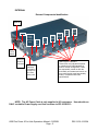
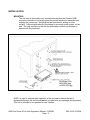
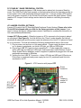
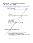
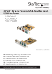
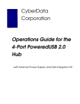
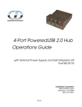
CyberData Corporation
USB PLUS POWER 6 PORT HUB
010630B
OPERATIONS MANUAL
February, 2004
Ops Manual 010630B
Revision B 02-16-04
PRODUCT DESCRIPTION
The CyberData USB PlusPower 6 Port Hub with the Stand-by Power Off Option
provides a simple and affordable way to add up to six Powered USB ports to your PC
that are controlled by the PC’s Stand-by/Wake commands. With this USB add-on, it
is easy to connect devices that need more than the standard USB interface supplied
500mA of +5 volts.
COMPATIBILITY
•
IBM PC Windows 98SE, 2000, XP, and Windows Me Compatible
•
Apple Computer Compatible
•
The USB 1.1 Standard is fully supported.
•
The HUB controller on this product is USB 1.1 compliant for a “powered HUB”.
FEATURES
•
6 powered-USB ports
•
One +24 volt at 2.0A
•
Three +12 volt at 1.0A each *
•
Two +5 volt at 1.0A each *
•
Short Circuit and over-current protected
•
No external Power Supply required
•
Plug-N-Play installation
•
Peripheral Power controlled by PC Stand-by/Wake commands
•
LED indicators to show port power output status
•
Two Year Warranty
* Note: This model changed from 500mA to 1.0A beginning with serial number 608000131
PRODUCT COMPONENTS (Included items)
•
CyberData USB PlusPower HUB (1)
•
Under-desk mounting brackets (2) w/screws (4)
•
Rubber Feet (4)
•
Instruction / Operations Manual (this document) (1)
•
Host USB cable strain relief clamp (1)
USB Plus Power 6 Port Hub Operations Manual 010630B
Page - 1
REV: B 02-16-2004
EXTERNAL
External Components Identification
AC Power
cable IN
Fan
Host
Cable
Clamp
Mounting Port 1
Hole
+5V
Upper
Port 2
+5V
Upper
Port 3
+12V
Upper
Port 4
+12V
Upper
Port 5
+12V
Upper
Port 6
+24V
Upper
On/Off
Power
Switch
USB
Series “B”
Host PC
Connector
Host LED
indicates
enumeration
and power to
the Plus
Power ports.
USB Port LED indicators.
These LEDs only indicate that power
is supplied to the USB standard “A”
ports. In normal configuration, LEDs
are sequentially turned on after the
hub initially enumerates and remain on
even when the hub goes into standby
mode in compliance with USB
specifications.
NOTE: The AC Power Cable is only supplied to US customers. User should use
ONLY a suitable Power Supply cord that conforms to IEC 60320/C13.
USB Plus Power 6 Port Hub Operations Manual 010630B
Page - 2
REV: B 02-16-2004
INSTALLATION
MOUNTING
The unit may be mounted in any orientation except that the Powered USB
connectors should not be facing upward to prevent conductive materials from
entering the connectors. Mounting feet are included for setting on a flat
surface. A Mounting Bracket Kit is included for mounting under a desk, on the
wall. The only restriction is that the fan and intake vents are not blocked or
have the air flow restricted.
Connections
PlusPower Hub
080132D2.dwg
or 080132D2.jpg
NOTE: In order to maintain safe operation of the unit and to reduce the risk of
equipment damage, this unit should not be mounted with any openings facing upward.
This unit is intended to be operated in a dry location.
USB Plus Power 6 Port Hub Operations Manual 010630B
Page - 3
REV: B 02-16-2004
CONNECTIONS
AC
The AC connection is a standard IEC type. This cable is supplied for North
American operations ONLY. If used outside of North America user should use
ONLY a suitable Power Supply cord that conforms to IEC 60320/C13
Input Requirements:
Voltage:
100 ~120 VAC or 200 ~ 240 VAC Auto Switching
Frequency:
60 / 50 Hz
Input Current: 6.0A (RMS) for 115VAC or 3.0A (RMS) for 230VAC
Host Connector
The Host connector is a standard USB “A” to “B” type cable and can be procured from
a variety of sources.
Max length of 6 meters (16.4 feet) with good quality cable
USB Plus Power 6 Port Hub Operations Manual 010630B
Page - 4
REV: B 02-16-2004
USB PlusPower connections
The PlusPower connections are a standard “A” type connector with 4 extra pins
designed to supply higher voltages. The “A” connector side of this product can be
used, by itself, without the locking PlusPower connector being used.
7/18/02
+Power Hub
Connector Keying
The PlusPower connectors are keyed in such a way as to only allow the correct
voltage cables to be installed.
Connector Keying Picture with Color Coding
Ivory
5 Volt Keyed
1 A each
Ports 1 & 2
Teal
Red
12 Volt Keyed
1 A each
Ports 3, 4, & 5
24 Volt Keyed
2A
Port 6
USB Plus Power 6 Port Hub Operations Manual 010630B
Page - 5
REV: B 02-16-2004
USB PlusPower Socket Connector Pin Assignments
PIN OUT
Pin
Signal Description
1
2
3
4
Vbus
DD+
Ground
USB standard
USB standard
USB standard
USB standard
5
6
7
8
Ground
Vplus
Vplus
Ground
USB PlusPower
USB PlusPower
USB PlusPower
USB PlusPower
Shell
Shield
USB Plus Power 6 Port Hub Operations Manual 010630B
Page - 6
“A”
“A”
“A”
“A”
REV: B 02-16-2004
PLUSPOWER CABLE SOURCES
USB PlusPower cable parts are manufactured by FCI/Berg Electronics.
http://www.fciconnect.com/
Partial or completed cable assemblies may be ordered from CyberData or they may be
procured from other sources.
For more information about the cables and connectors of PoweredUSB use the
following link: www.poweredusb.org
USB Plus Power 6 Port Hub Operations Manual 010630B
Page - 7
REV: B 02-16-2004
OPERATION
The device is a standard USB Hub compliant to the USB 1.1 specification, with the addition of
the Plus Powered ports. When connected to a Host, it enumerated as a "Generic USB Hub".
Current Maximums:
Standard USB Lower A supply:
Each lower portion of the A Ports provides +5V @ 500mA. If more than 500mA
is drawn from any port, that port goes into USB Over-current, the +5 volts is
turned off, and the fault condition is reported to the host according to USB 1.1
Specifications.
Plus Power USB Upper A supply:
+5V Ports (2) - 1A each
+12V Ports (3) - 1A each
+24V Port (1) - 2A
Each +5V and +12V Plus Power port is protected with a 1 Amp PTC (Positive
Temperature Coefficient) . The PTC may allow more that 1A to be drained.
The PTC will turn off the power for each individual port if an unusual overload is
sustained. Typically, a 1A PTC will shut off after approximately 15 seconds
drawing 1.5 Amps or more.
The +24V Port is also protected by a PTC that allows 2A continuous current.
This PTC will go into protection if a sustained overload is applied (For example,
with a 3 amp overload, the PTC will shut off after approximately 30 seconds).
FOR ALL PORTS:
Specific short protection is provided for the Standard USB connector and the
Plus Power connector.
Standard lower USB A portion of the connector
This portion of the connector will not support more that 500mA and the
power will be shut down immediately if any load is greater than 500mA.
Plus Power portion of the USB connector
This portion of the connector is a little more flexible and will allow for
temporary overloads. But, in all cases, the connector is protected
against short circuits. Should any Plus Power port be shorted, the HUB
will shut down completely until the short is removed. Depending on the
duration of the short, the power supply may need to be turned off using
the power switch on the side of the hub, for at least 30 seconds before it
can be turned on again.
USB Plus Power 6 Port Hub Operations Manual 010630B
Page - 8
REV: B 02-16-2004
PC STAND-BY / WAKE PERIPHERAL CONTROL
Under Windows operating systems, USB devices can be placed into low power Stand-by
mode. The USB Plus Power Hub expands on this feature and allows the operating system to
control power to the retail peripherals attached via the hub. A two-pin jumper (JP3) located
next to the power connector on the Printed Circuit Board controls this green feature. Please
read the JP3 Jumper Control settings section below for details on controlling the standby
feature.
JP3 JUMPER CONTROL SETTINGS
Jumper JP3 controls the PC Stand-by/Wake Peripheral Control feature. Please refer to the
Check-Off list shipped with your Hub for the factory set status of this jumper. If you
need to change the jumper setting please contact CyberData for a addendum instruction on
Hub case assembly/disassembly.
Jumper OFF (Green mode) - When the jumper on JP3 is removed or the jumper is placed
on a single pin (See Figure A), the Hub will be in the “Green” mode whereby the Hub will
shutdown all peripherals and the power supply fan whenever the Host PC is placed in Standby or is shut down. The Hub will exhibit the following characteristics when in this mode:
1) Plug in power cord and turn on Hub power switch – Power supply fan does not come
on, no power to peripherals, no Active LED light, no USB port LEDs light.
2) Plug in Host USB “B” Connector from operating PC – Power supply fan comes on,
Active LED light and USB port LEDs light, Hub enumerates under Windows Control
Panel System Device Manager, power is supplied to peripherals plugged into Hub and
peripherals enumerate in Windows.
3) Un-plug the Host USB “B” Connector – Active LED light and USB port LEDs stay on,
Plus power to peripherals and power supply fan turn off, peripherals and Hub lose
enumeration on PC.
Figure A – JP3 Connector with jumper OFF
Power
connector
JP3 Pin-1
and Pin2
Normally not
jumpered
USB Plus Power 6 Port Hub Operations Manual 010630B
Page - 9
JP4
Jumper in
normal “A”
position
REV: B 02-16-2004
Jumper ON - When the jumper is placed on both pins of JP3 the “Green” mode is disabled
(See Figure B). The Hub will exhibit the following characteristics when in this mode:
1) Plug in power cord and turn on Hub power switch – Power supply fan will come on,
power is supplied to peripherals, no Active LED light, and no USB port LED lights.
2) Plug in Host USB “B” Connector from operating PC – Active LED and USB port LEDs
light, Hub enumerates under Windows Control Panel, power is supplied to peripherals
plugged into Hub. Peripherals enumerate in Windows Control Panel System Device
Manager
3) Un-plug the Host USB “B” Connector – Active Light and USB port LEDs remain lit,
Plus power remains to peripherals, Power supply fan remains on, Peripherals and Hub
lose enumeration on PC.
Figure B – JP3 Connector with jumper ON
Jumper on
both pin-1
and pin-2
JP4 JUMPER CONTROL SETTINGS
Jumper JP4 controls the port sensing of the standard USB ports. In the “A” position lower
USB ports are active sensing under all operating systems. The “B” position is a special
custom setting that CyberData can utilize for particular applications. Normal position should
be “A”.
USB Plus Power 6 Port Hub Operations Manual 010630B
Page - 10
REV: B 02-16-2004
REGULATORY
FCC Statement:
This equipment has been tested and found to comply with the limits for a Class A
digital device, pursuant to Part 15 of the FCC Rules. These limits are designed to
provide reasonable protection against harmful interference when the equipment is
operated in a commercial environment. This equipment generates, uses, and can
radiate radio frequency energy and, if not installed and used in accordance with the
instruction manual, may cause harmful interference to radio communications.
Operation of this equipment in a residential area is likely to cause harmful interference
in which case the user will be required to correct the interference at his own expense.
See Appendix A for specifics.
CE Declaration of Conformity: See Appendix A
Safety Compliance: See Appendix A
License note:
"The PlusPower USB controller board contains certain technology covered by a patent held
by IBM Corporation. Cyberdata has obtained a license from IBM that permits Cyberdata,
among other things, to make and to sell or lease products that incorporate this technology.
The license also permits these products to be resold or released by any entity after they have
been initially sold by Cyberdata."
Documentation Note:
The documents, labels, and markings supplied are intended for English speaking countries
and users.
Contact Information:
CyberData Corporation
2555 Garden Rd.
Monterey, CA 93940
USA
831-373-2601 Voice
831-373-4193 Fax
USB Plus Power 6 Port Hub Operations Manual 010630B
Page - 11
REV: B 02-16-2004
Safety
Safety Standards(s):
• UL60950, 3rd Edition, Rev 03/02; Information Technology Equipment
• CSA C22.2 No. 60950-00, Information Technology Equipment
• EN60950 Jan. 2000, Information Technology Equipment
• IEC60950, Third Edition (1999), Information Technology Equipment
EMC
US/CAN
Complies with:
•
•
•
Title 47 of the CFR, Part 15, Subpart B, Section 15.107(b)
Title 47 of the CFR, Part 15, Subpart B, Section 15.109 (b)
ICES-003
CE
Complies with:
Directive 89/336/EEC
EN55022 Class A 1998:
• EN61000-3-2 1995
• EN61000-3-3 1995
EN55024: 1998
• EN61000-4-2: 1995
• EN 61000-4-3:1996
• ENV 50204: 1996
• EN 61000-4-4: 1995
• EN 61000-4-5: 1995
• EN 61000-4-6: 1996
• EN 61000-4-8: 1993
• EN 61000-4-11: 1995
USB Plus Power 6 Port Hub Operations Manual
Appendix A
4/15/2004