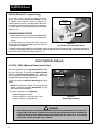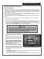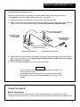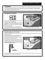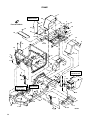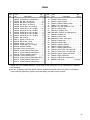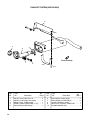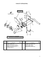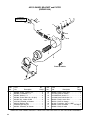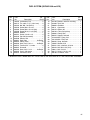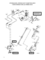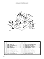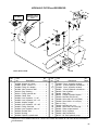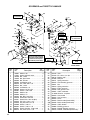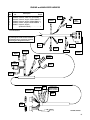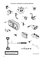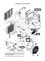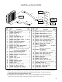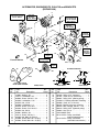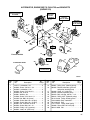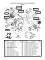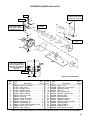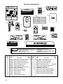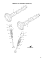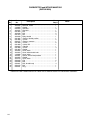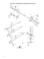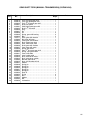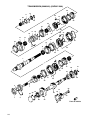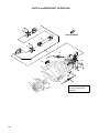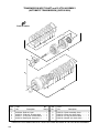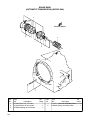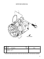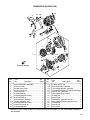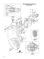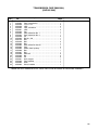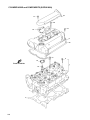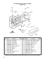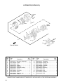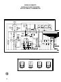
1
4120402 X SUZUKI K6A LIQUID COOLED GASOLINE ENGINE MT MODEL: 898627 SUZUKI K6A LIQUID COOLED GASOLINE ENGINE AT MODEL: 898628 SUZUKI 970 LIQUID COOLED GASOLINE ENGINE MODEL: 898671 PERKINS LIQUID COOLED DIESEL ENGINE MODEL: 898673 EC MODEL: 898695 Always Think Safety! Thank you for purchasing a Cushman, Textron product. You are one of our many customers who have voted their confidence in our company by purchasing our products. This is one of the best designed and built pieces of commercial industrial and turf equipment available. Many safety features have been designed and built into this product. Please DO NOT remove or defeat any safety features as they were installed for your protection. The useful life and good service you obtain from your vehicle depends to a large extent on the way it is maintained and operated. Treat your equipment properly, lubricate and adjust it as instructed in this manual and it will give you many years of reliable service. See your Cushman, Textron dealer for service and parts. He stocks genuine Cushman, Textron parts manufactured with the same precision and skill as the original parts. Cushman Inc., A Textron Company, reserves the right to make changes at any time, without notice, in specifications and models and also to discontinue models and the accessories designed to be used on these models. The right is also reserved to change specifications or parts at any time without incurring any obligation to equip same on models manufactured prior to date of such change. While the information contained in this parts manual is based on the latest product information available at the time of publication, the continuing accuracy of this parts manual cannot be guaranteed. ! WARNING • When replacement parts are required, use genuine CUSHMAN parts or parts with equivalent characteristics including type, strength and material. Failure to do so may result in product malfunction and possible injury to the operator and/or bystanders. Illustrations in this manual are a reference guide for parts identification only. Since these illustrations may not depict actual positioning of component parts, they should not be used as an assembly diagram. Doing so may result in improper assembly leading to sudden failure. MODIFICATIONS AND ACCESSORIES Factory installed modifications and accessories are available for use on this vehicle. Read and understand all literature before attempting to operate this vehicle or any attached equipment. NOTICE : Some vehicles may be equipped with special options that are not serviced by Cushman Textron. : The addition of accessories not of manufacturer’s design may result in erratic vehicle operation, improper battery charging and discharging, and failure of vehicle components. Direct any inquiries to: Customer Service Department P.O. Box 388 Augusta, GA 30903--0388 USA VEHICLE IDENTIFICATION NUMBERS ! WARNING • Altering this equipment in any manner which adversely affects the equipments operation, performance, durability or use, may cause hazardous conditions. IMPORTANT! THIS EQUIPMENT SHOULD NOT BE MODIFIED OR ADDED TO WITHOUT THE MANUFACTURER’S AUTHORIZATION. SPECIFICATION INFORMATION All information contained in this manual is the latest available at the time of printing. Cushman Textron reserves the right to make changes at any time without notice. NOTICE • After you identify a part by the reference number and the six digit cushman part number, always read the description of the part to be sure it is what you want. STANDARDS AND PUBLICATIONS This product meets requirements of ANSI B56.8 and has been approved by Factory Mutual Research Corporation to meet all Powered Industrial Truck portions (classification D or G) of the OSHA requirements (as stated in section 1910.178). Approved powered trucks shall bear a label or some other identifying mark indicating approval by the testing laboratory. This product conforms to EC directives and amendments: 89/392 & 91/368. Users, operators and service persons should be familiar with the following standards and publications: (The material may be obtained from the addresses shown). • Factory Mutual Approval Standard: Class No’s. 7811 & 7813; Gasoline or Diesel Powered Trucks, Types G, GS, D or DS. ADDRESS: Factory Mutual Research Corp. 1151 Boston--Providence Highway Norwood, Massachusetts 02062 U.S.A. • National Fire Protection Association: ANSI/NFPA #505; Powered Industrial Trucks. ADDRESS: National Fire Prevention Association Batterymarch Park Quincy, Massachusetts 02269 U.S.A. • ANSI/ASME B56.8 Personnel Burden Carriers ADDRESS: American National Standards Institute, Inc. 1430 Broadway New York, New York 10018 U.S.A. • ANSI/UL 558; Internal Combustion Engine Powered Industrial Trucks ADDRESS: American National Standards Institute, Inc. 1430 Broadway New York, New York 10018 U.S.A. OR Underwriters Laboratories Inc. 333 Pfingsten Road Northbrook, Illinois 60062 U.S.A. • Flammable and Combustible Liquids Code: ANSI/NFPA 30. ADDRESS: American National Standards Institute, Inc. 1430 Broadway New York, New York 10018 U.S.A. OR National Fire Prevention Association Batterymarch Park Quincy, Massachusetts 02269 U.S.A. 1 OPERATION CONTROL SYMBOLS And DECALS X 100 NOTICE THIS UNIT IS NOT A MOTOR VEHICLE WITHIN THE DEFINITION OF THE NATIONAL TRAFFIC MOTOR VEHICLE SAFETY ACT. IT IS NOT DESIGNED OR MANUFACTURED FOR USE ON ROADS, STREETS OR HIGHWAYS, NOR IS IT APPROPRIATE FOR SUCH USE. IT IS NOR MEANT TO BE LICENSED AS A MOTOR VEHICLE. 821071 Engine RPM This symbol indicates engine rpm’s. Park Brake Indicator Light This light will come on when the park brake is applied. Motor Vehicle Compliance This decal lets the operator know that the vehicle is not defined as a motor vehicle and therefore should not be driven on streets, roads or highways Battery (Voltmeter) Charging This symbol appears on the voltmeter gauge. This gauge indicates the charging of the battery. OFF DIM BRIGHT 009034880 Electric Cooling Fan Warning This decal warns the operator keep hands away from the cooling fan, the cooling fan can start at any time even with the ignition key in the OFF position. Headlight Switch Positions These symbols appear on the light switch. As indicated, each one represents the headlights functions. 844643 P.T.O. Warning This decal warns the operator that an uncovered P.T.O. can cause entanglement of clothing and/or body parts. WARNING PARKING BRAKES ARE NOT AUTOMATICALLY APPLIED. VEHICLE MAY MOVE CAUSING PERSONAL INJURY AND/OR PROPERTY DAMAGE. ALWAYS APPLY HAND OR FOOT BRAKES. 822819 Park Brake Warning This decal warns the operator that the park brake is not automatically applied. Engine Oil Pressure Light This light will come on when the ignition key is turned to the ON position and when the engine is started (it will shut off once the engine is running). Its main function is to warn the operator if the oil pressure gets to low. If this light comes on during normal vehicle operation, stop the vehicle and check for problems Fuel Level Indicator This symbol appears on the fuel gauge. The fuel gauge indicates the amount of fuel in the fuel tank 840845 This symbol indicates diesel fuel only Water Temperature Gauge This symbol appears on the water temperature gauge. This gauge warns the operator if the coolant system is overheating. 840748 Radiator Coolant Warning This decal warns the operator not to remove the radiator cap when the engine is hot. Refer to the Cooling System Section in this manual for proper safety and operating instructions. WARNING FAILURE TO HEED THESE WARNINGS MAY RESULT IN SERIOUS INJURY OR DEATH 1. 2. 3. 4. 5. READ AND UNDERSTAND ALL LABELS AND THE OPERATOR’S MANUAL. DO NOT ALLOW UNTRAINED PERSONNEL TO OPERATE THIS VEHICLE. DO NOT MODIFY THIS VEHICLE WITHOUT MANUFACTURER’S AUTHORIZATION. PLACE LOADS FORWARD OF REAR AXLE. TOP HEAVY LOADS CAN CAUSE UPSETTING. DO NOT EXCEED PAYLOAD CAPACITY. 6. DO NOT OPERATE IF REPAIRS ARE REQUIRED. 7. KEEP ALL SHIELDS IN PLACE. Read the Operator’s Manual This decal informs the operator to read and understand the Operator’s manual. To prevent injury, they must be familiar with the operation of this product and be fully aware of safe operating procedures. 8. SHIFT INTO NEUTRAL OR PARK BEFORE STARTING ENGINE. 9. ONLY CARRY PASSENGERS IN SEATS PROVIDED. 10. WHEN PARKING (LEAVING) VEHICLE, FOLLOW ALL INSTRUCTIONS IN OPERATOR’S MANUAL. 11. AVOID SUDDEN STARTS, STOPS AND SHARP TURNS ESPECIALLY ON SLOPES, OR WITH HEAVY LOADS 12. KEEP ALL LABELS AND INSTRUCTIONAL LITERATURE LEGIBLE AND INTACT. 13. KEEP ARMS AND LEGS WITHIN VEHICLE BODY. 845038 Vehicle Operation This decal informs the operator of proper procedures for safely operating the vehicle. Read this manual completely to become aware of other safety issues and operating procedures which will help you operate this vehicle in a safe and responsible manner. 2 840901 SERVICE and MAINTENANCE INDEX Page A Accelerator Pedal . . . . . . . . . . . . . . . . . . . . . . . . . Accessories, list of . . . . . . . . . . . . . . . . . . . . . . . . . Accessory Power Plug . . . . . . . . . . . . . . . . . . . . . Access Panels . . . . . . . . . . . . . . . . . . . . . . . . . . . . Air Cleaner . . . . . . . . . . . . . . . . . . . . . . . . . . . . . . . Air Cleaner Element . . . . . . . . . . . . . . . . . . . . . . . 13 42 10 32 31 31 B Battery . . . . . . . . . . . . . . . . . . . . . . . . . . . . . . . . . . 26 Brake Lever, Parking . . . . . . . . . . . . . . . . . . . . . . . 12 Brake Pedal, Service . . . . . . . . . . . . . . . . . . . . . . 13 Brake Fluid Indicator Light . . . . . . . . . . . . . . . 10, 37 Brake Fluid Level & Bleeding . . . . . . . . . . . . . . . 37 Bulbs and Bulb Replacement . . . . . . . . . . . . 34, 39 C Choke knob (970 Suzuki only) . . . . . . . . . . . . . . . 12 Clutch Interlock Switch . . . . . . . . . . . . . . . . . . . . . 12 Clutch Pedal . . . . . . . . . . . . . . . . . . . . . . . . . . . 12, 22 Controls . . . . . . . . . . . . . . . . . . . . . . . . . . . . . . . 10-13 Cooling System . . . . . . . . . . . . . . . . . . . . . . . . 18-19 D Dash Panel Dipswitch Settings . . . . . . . . . . . . . . 43 Decals . . . . . . . . . . . . . . . . . . . . . . . . . . . . . . . . . . . . 2 Differential, 11.16:1 & 14.21:1 . . . . . . . . . . . . . . . 40 Differential, 2-Speed (operation) . . . . . . . . . . . . . 44 E Engine: Access . . . . . . . . . . . . . . . . . . . . . . . . . . . . 14-15 Break--in . . . . . . . . . . . . . . . . . . . . . . . . . . . . . 14 Cooling . . . . . . . . . . . . . . . . . . . . . . . . . . . . 18-19 Identification Numbers . . . . . . . . . . . . . . . . . . 6-7 Oil Level . . . . . . . . . . . . . . . . . . . . . . . . . . . 15-16 Pre-starting Check . . . . . . . . . . . . . . . . . . . . . 15 Starting: Automatic Transmission . . . . . . . . . . . . . . . 22 Manual Transmission . . . . . . . . . . . . . . . 21-22 Manual Transmission (diesel) . . . . . . . . 23-24 F Fuel Gauge . . . . . . . . . . . . . . . . . . . . . . . . . . . . 10, 20 Fuel Specifications . . . . . . . . . . . . . . . . . . . . . . . . 20 Front Cowl Access . . . . . . . . . . . . . . . . . . . . . . . . 32 Release Lever . . . . . . . . . . . . . . . . . . . . . . . . 32 Fuses . . . . . . . . . . . . . . . . . . . . . . . . . . . . . . . . . . . . 34 G Gasoline Containing Alcohol . . . . . . . . . . . . . . . . 20 Gauges . . . . . . . . . . . . . . . . . . . . . . . . . . . . . . . . . . 10 Gear Selector: Automatic Transmission . . . . . . . . . . . . . . . . 13 Manual Transmission . . . . . . . . . . . . . . . . . . 13 General Information . . . . . . . . . . Inside Front Cover Governor Oil Level . . . . . . . . . . . . . . . . . . . . . . . . 40 Governor & Throttle Hand Control . . . . . . . . . . . 46 H Headlight Replacement . . . . . . . . . . . . . . . . . . . . 39 Horn Button . . . . . . . . . . . . . . . . . . . . . . . . . . . . . . 11 Hour Meter . . . . . . . . . . . . . . . . . . . . . . . . . . . . . . . 10 Hydraulic Lift System . . . . . . . . . . . . . . . . . . . . . . 44 Hydraulic P.T.O. . . . . . . . . . . . . . . . . . . . . . . . . 48-49 Hydraulic Reservoir . . . . . . . . . . . . . . . . . . . . . . . . 51 Page I Ignition Switch . . . . . . . . . . . . . . . . . . . . . . . . . . . . 11 Interlock Switch, Clutch . . . . . . . . . . . . . . . . . . . . 12 J Jacks, Jacking Locations And Using A Hoist: 28-29 Jump Starting . . . . . . . . . . . . . . . . . . . . . . . . . . 26-27 L Light Switch . . . . . . . . . . . . . . . . . . . . . . . . . . . . . . 11 Lubrication Chart . . . . . . . . . . . . . . . . . . . . . . . . . . 33 Lubrication Recommendations . . . . . . . . . . . . 8, 33 M Maintenance Guide . . . . . . . . . . . . . . . . . . . . . 35-36 Master Cylinder Reservoir (brake fluid) . . . . . . . 37 Mechanical P.T.O. . . . . . . . . . . . . . . . . . . . . . . 46-47 O Oil Warning Light . . . . . . . . . . . . . . . . . . . . . . . 10, 16 Oil Level (engine) . . . . . . . . . . . . . . . . . . . . . . 15-16 P Park Brake Lever and Adjustment . . . . . . . . 12, 38 Parts Illustrations . . . . . . . . . . . . . . . . . . . . . . 52-177 Power Steering Reservoir . . . . . . . . . . . . . . . . . . 21 Pre-Starting Check List . . . . . . . . . . . . . . . . . . . . . 15 P.T.O. Operation . . . . . . . . . . . . . . . . . . . . . . . 46-50 Purge Fuel System (Diesel) . . . . . . . . . . . . . . 24-25 R Remote Hydraulics . . . . . . . . . . . . . . . . . . . . . . . . 45 Reservoir, Hydraulic . . . . . . . . . . . . . . . . . . . . . . . 51 S Safety Instructions . . . . . . . . Inside Front Cover, 14 Specifications . . . . . . . . . . . . . . . . . . . . . . . . . . . . . 8-9 Starting the engine: With Automatic Transmission . . . . . . . . . . . . 22 With Manual Transmission . . . . . . . . . . . 21-22 Diesel (with manual transmission) . . . . . 23-24 T Tachometer . . . . . . . . . . . . . . . . . . . . . . . . . . . . . . . 10 Taillight Replacement . . . . . . . . . . . . . . . . . . . . . . 39 Tire Air Pressure . . . . . . . . . . . . . . . . . . . . . . . . . . 21 Tire Removal and Replacement: Front . . . . . . . . . . . . . . . . . . . . . . . . . . . . . . . . 30 Rear . . . . . . . . . . . . . . . . . . . . . . . . . . . . . . . . . 30 Towing a Trailer . . . . . . . . . . . . . . . . . . . . . . . . . . . 43 Towing The Vehicle: Automatic Transmission . . . . . . . . . . . . . . . . 28 Manual Transmission . . . . . . . . . . . . . . . 27-28 Transmission, Manual . . . . . . . . . . . . . . . . . . . . . . 41 Automatic . . . . . . . . . . . . . . . . . . . . . . . . . . . . 42 V Vehicle Identification Number . . . . . . . . . . . . . . . . 6 Voltmeter . . . . . . . . . . . . . . . . . . . . . . . . . . . . . . . . . 10 W Water Temp. Gauge & Overheat Buzzer 10, 17-18 3 PARTS ILLUSTRATIONS INDEX PARTS Page A Accelerator pedal . . . . . . . . . . . . . . . . . . . . . . . . . . . . . . . . . 71 Accessory power plug (12 volt) . . . . . . . . . . . . . . . . . . 92--93 Air cleaner, Bracket and Filter: Suzuki K6A . . . . . . . . . . . . . . . . . . . . . . . . . . . . . . . . . . 62 Suzuki 970 & Perkins diesel . . . . . . . . . . . . . . . . . . . . 63 Alternator, Engine belts, Pulleys & Brackets: Suzuki K6A . . . . . . . . . . . . . . . . . . . . . . . . . . . . . . . . . . 96 Suzuki 970 . . . . . . . . . . . . . . . . . . . . . . . . . . . . . . 97, 164 Perkins diesel . . . . . . . . . . . . . . . . . . . . . . . . . . . . . . . . 98 Automatic transmission (Suzuki K6A) . . . . . . . . . . . 120,121 Axle, rear . . . . . . . . . . . . . . . . . . . . . . . . . . . . . . . . . . . . . . . . 83 B Belts, engine . . . . . . . . . . . . . . . . . . . . . . . . . . . . . . . 96, 97, 98 Body, Hood, Headlights . . . . . . . . . . . . . . . . . . . . . . . . 54--55 Brake band (automatic transmission) . . . . . . . . . . . . . . . 132 Brake lever (parking) . . . . . . . . . . . . . . . . . . . . . . . . . . . . . . 70 Brake pedal (service) . . . . . . . . . . . . . . . . . . . . . . . . . . 64--65 Brake lines . . . . . . . . . . . . . . . . . . . . . . . . . . . . . . . . . . . 64--65 Brake cylinder (master) . . . . . . . . . . . . . . . . . . . . . . . . . 64--65 Brake fluid reservoir and bracket . . . . . . . . . . . . . . . . . 64--65 Brakes, front & rear . . . . . . . . . . . . . . . . . . . . . . . . . . . . 64--65 C Cables: Choke (Suzuki 970 only) . . . . . . . . . . . . . . . . . . . . 52--53 Clutch . . . . . . . . . . . . . . . . . . . . . . . . . . . . . . . . . . . . . . . 79 Shifter . . . . . . . . . . . . . . . . . . . . . . . . . . . . . . . . . . . 81--82 Two-speed differential control . . . . . . . . . . . . . . . . 88, 89 Cam Chain (Suzuki K6A) . . . . . . . . . . . . . . . . . . . . . 107--108 Camshaft & components (Suzuki K6A) . . . . . . . . . 105--106 Camshaft & components (Suzuki 970) . . . . . . . . . . . . . . 123 Carburetor (Suzuki K6A) . . . . . . . . . . . . . . . . . . 109--110, 112 Carburetor (Suzuki 970) . . . . . . . . . . . . . . . . . . . . . . . . . . 125 Catalytic convertor (Suzuki K6A) . . . . . . . . . . . . . . . . . . . . 59 Coil, ignition: (Suzuki K6A) . . . . . . . . . . . . . . 52--53, 92--93 (Suzuki 970) . . . . . . . . . . . . . . . 52--53, 92--93 Console panel . . . . . . . . . . . . . . . . . . . . . . . . . . 52--53, 56--57 Clutch assembly (automatic transmission) . . . . . . . . . . . 128 Clutch: (Suzuki K6A) . . . . . . . . . . . . . . . . . . . . . 79, 118--119 (Perkins diesel & Suzuki 970) . . . . . . . 80, 100--101 Clutch pedal cable (gasoline) . . . . . . . . . . . . . . . . . . . . . . . 79 Clutch linkage (diesel) . . . . . . . . . . . . . . . . . . . . . . . . . . . . . 80 Cover, engine . . . . . . . . . . . . . . . . . . . . . . . . . . . . . . . . . 52--53 Cooling System . . . . . . . . . . . . . . . . . . . . . . . . . . . . . . . 94--95 Cowl, front . . . . . . . . . . . . . . . . . . . . . . . . . . . . . . . . . . . . 54--55 Crankshaft (Suzuki K6A) . . . . . . . . . . . . . . . . . . . 96, 154--155 Crankshaft (Suzuki 970) . . . . . . . . . . . . . . . . . . . . . . . 97, 159 Cylinder, hydraulic lift . . . . . . . . . . . . . . . . . . . . . . . . . . . . . . 85 Cylinder block, engine: (Suzuki K6A) . . . . . . . . . . 150--151 (Suzuki 970) . . . . . . . . . . . . . . . 158 Cylinder head, engine: (Suzuki K6A) . . . . . . . . . . 148--149 (Suzuki 970) . . . . . . . . . . . . . . . 157 D Decals . . . . . . . . . . . . . . . . . . . . . . . . . . . . . . . . . . . . . . . . . 104 Delivery pipe (Suzuki K6A) . . . . . . . . . . . . . . . . . . . . . . . . 141 Differential (two-speed) . . . . . . . . . . . . . . . . . . . . . . . . . . . 88 Dipstick, oil: (Suzuki K6A) . . . . . . . . . . . . . . . 121, 152--153 (Suzuki 970) . . . . . . . . . . . . . . . . . . . . . . . 158 Dipstick, transmission (Suzuki K6A auto.) . . . . . . . . . . . 121 4 Page Distributor (Suzuki K6A) . . . . . . . . . . . . . . . . . . . . . . . . . . 136 Distributor (Suzuki 970) . . . . . . . . . . . . . . . . . . . . . . . 157, 165 Drawbar . . . . . . . . . . . . . . . . . . . . . . . . . . . . . . . . . . . . . . 56--57 Driveshaft: (Suzuki K6A) . . . . . . . . . . . . . . . . . . . . . 118--119 (Perkins diesel & Suzuki 970) . . . . . . . 100--101 Automatic transmission . . . . . . . . . . . . 120, 121 E Electrical components . . . . . . . . . . . . . . . . . . . . . . . . . . 92--93 Emissions control (Suzuki K6A) . . . . . . . . . . . . . . . . . . . . 139 Emissions control (Suzuki 970) . . . . . . . . . . . . . . . . . . . . 126 Engine mounts: (Suzuki K6A & 970) . . . . . . . . . . . . . . . . 102 (Perkins diesel) . . . . . . . . . . . . . . . . . . . 103 Exhaust system: (Suzuki K6A) . . . . . . . . . . . . . . . . . 58, 139 (Suzuki K6A)(Catalytic Converter) . . . 59 (Suzuki 970 & Perkins diesel) . . . . 60--61 F Fan, radiator cooling . . . . . . . . . . . . . . . . . . . . . . . . . . . 94--95 Fenders (rear) . . . . . . . . . . . . . . . . . . . . . . . . . . . . . . . . . 56--57 Filter, air cleaner (Suzuki K6A) . . . . . . . . . . . . . . . . . . . . . . 62 Filter, air cleaner (Suzuki 970 & diesel) . . . . . . . . . . . . . . . 63 Filter, oil: (Suzuki K6A) . . . . . . . . . . . . . . . . . . . . . . . 150--151 (Suzuki 970) . . . . . . . . . . . . . . . . . . . . . . . . . . . 158 Flywheel (Suzuki K6A) . . . . . . . . . . . . . . . . . . . . . . . 154--155 Flywheel (Suzuki 970) . . . . . . . . . . . . . . . . . . . . . . . . . . . . 159 Foot throttle, Cable and Linkage . . . . . . . . . . . . . . . . . . . . 71 Fuel controller (automatic transmission) . . . . . . . . . . . 92--93 Fuel injector assembly (Suzuki K6A) . . . . . . . . . . . . . . . 141 Fuel system: Suzuki K6A & 970 . . . . . . . . . . . . . . . . 66--67 Filter . . . . . . . . . . . . . . . . . . . . . . . . . . . 66--67 Pump . . . . . . . . . . . . . . . . . . . . . . 66--67, 140 Tank . . . . . . . . . . . . . . . . . . . . . . . . . . . 66--67 Fuel system: Perkins diesel . . . . . . . . . . . . . . . . . . . 68--69 Filter . . . . . . . . . . . . . . . . . . . . . . . . . . . 68--69 Pump . . . . . . . . . . . . . . . . . . . . . . . . . . 68--69 Tank . . . . . . . . . . . . . . . . . . . . . . . . . . . 68--69 Frame . . . . . . . . . . . . . . . . . . . . . . . . . . . . . . . . . . . . . . . 56--57 Front Cowl . . . . . . . . . . . . . . . . . . . . . . . . . . . . . . . . . . . . 54--55 G Gaskets, engine (Perkins) . . . . . . . . . . . . . . . . . . . . . . 68--69 Gaskets, engine (Suzuki K6A) . . . . . . . . . . . . . 121, 146--147 Gaskets, engine (Suzuki 970) . . . . . . . . . . . . . . . . . . . . . 156 Gear shift fork (manual) (Suzuki K6A) . . . . . . . . . . . 114--115 Gear shift fork (Suzuki 970 & Perkins diesel) . . . . . . . . . 162 Generator (Suzuki K6A) . . . . . . . . . . . . . . . . . . . . . . . . . . 143 Governor (Suzuki K6A & 970) . . . . . . . . . . . . . . . . . . . 90, 99 Governor hand control (Perkins diesel) . . . . . . . . . . . . . . 89 Governor hand control (Suzuki K6A & 970) . . . . . . . . 88, 99 Governor & throttle linkage (Suzuki K6A & 970) . . . . . . . 90 H Hand controls (gasoline) . . . . . . . . . . . . . . . . . . . . . . . . . . . 88 Hand controls (diesel) . . . . . . . . . . . . . . . . . . . . . . . . . . . . . 89 Headlights . . . . . . . . . . . . . . . . . . . . . . . . . . . . . . . . . . . . 54--55 Horn . . . . . . . . . . . . . . . . . . . . . . . . . . . . . . . . . . . . . . . . . 54--55 Horn button . . . . . . . . . . . . . . . . . . . . . . . . . . . . . . . . . . . 92--93 Hood release latch . . . . . . . . . . . . . . . . . . . . . . . . . . . . . 54--55 Housing, transmission: automatic (Suzuki K6A) . . . . 121 manual (Suzuki K6A) . . 116--117 Housing, transmission Suzuki 970 & diesel . . . . . . . . . . 161 Hubs, wheel: front . . . . . . . . . . . . . . . . . . . . . . . 74--75, 76--77 H Hydraulic brake lines . . . . . . . . . . . . . . . . . . . . . . . . . . . 64--65 Hydraulics: Control box cover . . . . . . . . . . . . . . . . . . . . . . . . . . 84, 87 Control valve . . . . . . . . . . . . . . . . . . . . . . . . . . . . . . . . . 86 Filter . . . . . . . . . . . . . . . . . . . . . . . . . . . . . . . . . . . . . . . . 87 Lift cylinder . . . . . . . . . . . . . . . . . . . . . . . . . . . . . . . . . . 85 Lift system . . . . . . . . . . . . . . . . . . . . . . . . . . . . . . . . . . . 85 Pump . . . . . . . . . . . . . . . . . . . . . . . . . . . . . . . . . . . . 84, 87 Reservoir . . . . . . . . . . . . . . . . . . . . . . . . . . . . . . . . . . . . 87 Selector valve . . . . . . . . . . . . . . . . . . . . . . . . . . . . . . . . 84 Valve system . . . . . . . . . . . . . . . . . . . . . . . . . . . . . . . . . 84 Hydraulic reservoir guard . . . . . . . . . . . . . . . . . . . . . . . 56--57 I Idle-up controller (automatic transmission) . . . . . . . . . . . . 93 Ignition switch . . . . . . . . . . . . . . . . . . . . . . . . . . . . . . . . . 92--93 Input shaft & gears: Suzuki K6A manual transmission . . . . . . . . . . 116--117 Suzuki K6A automatic transmission . . . . 128, 120, 121 Suzuki 970 & diesel . . . . . . . . . . . . . . . . . . . . . . . . . . 160 Instrument panel w/tach . . . . . . . . . . . . . . . . . . . . . . . . 92--93 Intake manifold (Suzuki K6A) . . . . . . . . . . . . . . . . . . 109--110 Intake manifold (Suzuki 970) . . . . . . . . . . . . . . . . . . . . . . 125 L Leaf springs . . . . . . . . . . . . . . . . . . . . . . . . . . . . . . . . . . . . . 83 Light switch . . . . . . . . . . . . . . . . . . . . . . . . . . . . . . . . . . . 92--93 Lower ROPS . . . . . . . . . . . . . . . . . . . . . . . . . . . . . . . . . . 56--57 M R Radiator . . . . . . . . . . . . . . . . . . . . . . . . . . . . . . . . . . . . . . 94--95 Rear platform . . . . . . . . . . . . . . . . . . . . . . . . . . . . . . . . . 56--57 Rear springs, shackles . . . . . . . . . . . . . . . . . . . . . . . . . . . . 83 S Seats . . . . . . . . . . . . . . . . . . . . . . . . . . . . . . . . . . . . . . . . 52--53 Shifter & shifter linkage: . . . . . . . . . . . . . . . . . . . . . . . . 81--82 Shifter & shifter linkage (970 Suzuki & diesel) . . . . 100--101 Shifter gears: Suzuki K6A manual transmission . . . . . . . . . . 114--115 Shift shaft (automatic transmission) . . . . . . . . . . . . . . . . 122 Shift switch (automatic transmission) . . . . . . . . . . . . . . . 122 Shock absorbers: rear . . . . . . . . . . . . . . . . . . . . . . . . . . . . 83 front (strut assembly) . . . . 74--75, 76--77 Solenoid (Suzuki K6A) . . . . . . . . . . . . . . . . . . . . . . . . . 92--93 Solenoid, oil pump (automatic transmission) . . . . . 121, 122 Spark plugs (Suzuki K6A) . . . . . . . . . . . . . . . . . . . 148--149 (Suzuki 970) . . . . . . . . . . . . . . . . . . . . . . . . 157 Starter: manual transmission . . . . . . . . . . . . . . . . . . . . . . 142 automatic transmission . . . . . . . . . . . . . . . . . . . . 135 Starter (Suzuki 970) . . . . . . . . . . . . . . . . . . . . . . . . . . . . . . 163 Steering wheel, Shaft & Pump . . . . . . . . . . . . . . . . . . . 72--73 Struts, front (spring & shock) . . . . . . . . . . . . . . 74--75, 76--77 Suspension, front . . . . . . . . . . . . . . . . . . . . . . . . 74--75, 76--77 T Oil cooler (automatic transmission) . . . . . . . . . . . . . . 94--95 Oil filter (Suzuki K6A) . . . . . . . . . . . . . . . . . . . . . . . . 150--151 (Suzuki 970) . . . . . . . . . . . . . . . . . . . . . . . . . . . . 158 Oil pan, Gasket and Dipstick: (Suzuki K6A) manual transmission . . . . . . . . . 152--153 (Suzuki K6A) automatic transmission . . . . . . . 121, 122 (Suzuki 970) . . . . . . . . . . . . . . . . . . . . . . . . . . . . . . . . 158 Oil pump (Suzuki K6A) . . . . . . . . . . . . . . . . . . . . . . . 113, 122 Oil pump (Suzuki 970) . . . . . . . . . . . . . . . . . . . . . . . . . . . . 127 Output gears (automatic transmission) . . . . . . . . . . . . . . 130 Output shaft (automatic transmission) (Suzuki K6A) . . 130 Taillight . . . . . . . . . . . . . . . . . . . . . . . . . . . . . . . . . . . . . . . 92--93 Tailpipe: (Suzuki K6A) . . . . . . . . . . . . . . . . . . . . . . . . . . . . 58 (Suzuki K6A) (Catalytic converter) . . . . . . . . . . 59 (Suzuki 970 & Perkins diesel) . . . . . . . . . . 60--61 Thermostat . . . . . . . . . . (Suzuki 970) 95, (Suzuki K6A) 138 Throttle hand control (Perkins diesel) . . . . . . . . . . . . . . . . 89 Throttle hand control (Suzuki K6A & 970) . . . . . . . . . . . . 88 Throttle linkage (Suzuki K6A & 970) . . . . . . . . . . . . . . . . . 90 Tie rods . . . . . . . . . . . . . . . . . . . . . . . . . . . . . . . . 74--75, 76--77 Timing belts & cover (Suzuki K6A) . . . . . . . . . . . . . 107--108 Timing belts & cover (Suzuki 970) . . . . . . . . . . . . . . . . . . 124 Tires, front and rear . . . . . . . . . . . . . . . . . . . . . . . . . . . . . . . 78 Torque chart and torque specifications . . . . . . . . . . . . . . 168 Torque converter (automatic transmission) . . . . . . . . . . 120 Transmissions: (Suzuki K6A) (manual) 116--117, , 144--145 (Suzuki K6A) (automatic) . . . . . . . 120-131 (Suzuki 970 & Perkins diesel) . . . . . . . 161 Transmission mounts: (Suzuki K6A & 970) . . . . . . . . . . 102 (Perkins diesel) . . . . . . . . . . . . . 103 Transmission tubes (automatic transmission) . . . . . . . . 122 Transmission valve (automatic transmission) . . . . 132--133 P W Manifold, exhaust (Suzuki K6A) . . . . . . . . . . . . . . . . . . . . 139 Manifold, exhaust (Suzuki 970) . . . . . . . . . . . . . . . . . . . . 126 Master cylinder reservoir . . . . . . . . . . . . . . . . . . . . . . . . 64--65 Mud flap (front) . . . . . . . . . . . . . . . . . . . . . . . . . . . . . . . . 54--55 Muffler: (Suzuki K6A) . . . . . . . . . . . . . . . . . . . . . . . . . . . . . 58 (Suzuki 970) . . . . . . . . . . . . . . . . . . . . . . . . . . . . . 60 (Perkins diesel) . . . . . . . . . . . . . . . . . . . . . . . . . . . 61 Motor mounts: (Suzuki K6A & 970) . . . . . . . . . . . . . . . . 102 (Perkins diesel) . . . . . . . . . . . . . . . . . . . 103 O Park brake, Lever and Cable . . . . . . . . . . . . . . . . . . . . . . . 68 Parking brake (automatic transmission)(Suzuki K6A) . . 131 Perkins Diesel Engine Information . . . . . . . . . . . . . . . 68--69 PCV valve (Suzuki K6A) . . . . . . . . . . . . . . . . . . . . . . . . . . . 111 PCV valve (Suzuki 970) . . . . . . . . . . . . . . . . . . . . . . . . . . 126 Pistons (Suzuki K6A) . . . . . . . . . . . . . . . . . . . . . . . . . 154--155 Pistons (Suzuki 970) . . . . . . . . . . . . . . . . . . . . . . . . . . . . . 159 Planetary gears (automatic transmission) . . . . . . . . . . . 129 Power steering pump . . . . . . . . . . . . . . . . . . . . . . . . . . 72--73 PTO mechanical (Suzuki 970 and diesel only) . . . 166--167 Pulleys (Suzuki K6A) . . . . . . . . . . . . . . . . . . . . . . . . . . . . . . 96 Pulleys (Suzuki 970) . . . . . . . . . . . . . . . . . . . . . . . . . . . . . . 97 Pulleys (Perkins diesel) . . . . . . . . . . . . . . . . . . . . . . . . . . . . 98 Water hose (Suzuki K6A) . . . . . . . . . . . . . . . . . . . . . . . . . 138 Water pump (Suzuki K6A) . . . . . . . . . . . . . . . . . . . . . . . . 137 Water pump (Suzuki 970) . . . . . . . . . . . . . . . . . . . . . . . . . 127 Water temp. sender . . . . . . . . . . . . . . . . . . . . . . . . . . . . 92--93 Wire harness: ATM controller . . . . . . . . . . . . . . . . . . . . . . . . . . . . . . 92--93 Engine . . . . . . . . . . . . . . . . . . . . . . . . . . . . . . . . . . . . . . . . 91 Fuel tank . . . . . . . . . . . . . . . . . . . . . . . . . . . . . . . . . . . 92--93 Main . . . . . . . . . . . . . . . . . . . . . . . . . . . . . . . . . . . . . . . . . 91 Taillight . . . . . . . . . . . . . . . . . . . . . . . . . . . . . . . . . . . . 92--93 Wiring diagrams . . . . . . . . . . . 170--173, 178--179, 182--183 Wiring schematics . . . . . . . . . 175--177, 180--181, 184--185 5 VEHICLE IDENTIFICATION NUMBERS VEHICLE IDENTIFICATION NUMBERS IMPORTANT! This unit is not a motor vehicle within the definition of the national traffic motor vehicle safety act. It is not designed or manufactured for use on roads, streets or highways. It is not appropriate for such use. This unit is not meant to be licensed as a motor vehicle. SPARK ARRESTERS ARE REQUIRED BY CALIFORNIA PUBLIC RESOURCES CODE, SECTIONS 4428--4442, WHEN OPERATING ANY INTERNAL COMBUSTION ENGINE ON HYDROCARBON FUELS, ON FOREST--, BRUSH--, OR GRASS--COVERED LANDS. NOTICE • Reference to the front, rear, left and right sides of the vehicle are always determined by the operator’s seated position. THE FOLLOWING IDENTIFICATION NUMBERS MUST APPEAR ON ALL CORRESPONDENCE CONCERNING THIS VEHICLE. The Vehicle Identification Number (VIN), model number and serial number are all printed on the Nameplate/Identification Decal attached to the crossmember under the dash (See Fig. 1). The serial number and model number are also stamped on the crossmember. It is located to the left of the model and serial no. decals (See Fig. 2). Vehicle Serial No. Stamped Into Crossmember Vehicle Model and Serial No. Figure 1 Nameplate / Identification Decal Figure 2 Serial Number And Model Number ENGINE IDENTIFICATION NUMBERS Your Cushman Turf-Truckster is equipped with one of three power sources: A Suzuki K6A 3 cylinder, 4 cycle, liquid--cooled gasoilne powered engine; a Suzuki 970 4-cylinder, 4-cycle, liquid-cooled gasoline powered engine, or a Perkins 103-10, 3-cylinder, 4-cycle liquid-cooled diesel powered engine. 6 VEHICLE IDENTIFICATION NUMBERS Cont. Engine Identification Numbers (con’t.) Each engine has a serial number stamped onto the engine block. The Perkins diesel’s serial no. is stamped on a metal plate which is attached to the engine block. The Engine Serial No. for the Suzuki K6A engine is stamped onto the upper engine block on the left side of the engine. Engine Serial No. K6A Suzuki It’s located on top of the engine, beneath the governor bracket and may be partially hidden by the electrical convoluted tubing which passes through that area. The engine serial no. is also hand printed on the engine cylinder cover (See Fig. 3). Figure 3 Suzuki K6A Engine Serial Number Engine Serial No. 970 Suzuki The Engine Serial No. for the Suzuki 970 engine is stamped onto the lower engine block on the right side of the engine. It’s located on the lower engine block beneath the air cleaner. The 970 engine serial no. is also hand printed on the engine cylinder cover. Figure 4 Suzuki 970 Engine Serial Number (As Viewed From the Drivers Side of Vehicle) The Engine Serial No. for the Perkins Diesel engine is stamped onto a metal plate on the upper engine block on the left side of the engine. Engine Serial No. Perkins Diesel Figure 5 Perkins Diesel Engine Serial Number 7 SPECIFICATIONS SPECIFICATIONS Specifications subject to change without notice. Rear Axles: Models 898671, 898673 & 898695 . . . . . . . . . . . 11.16:1 2-speed hypoid differential Transmission: Models 898671, 898673 & 898695 . . . . . . . . . . . 4-speed manual with low-low (creeper) 1st gear, synchronized in all forward speeds All turf models are equipped with a hydraulic brake system and a lever operated parking brake integral to the rear brake drums. CAPACITIES FUEL Fuel Tank . . . . . . . . . . . . . . . . . . . . . . . . 6.5 gal. (24.5 L) Gasoline Engines . . . . . . . . . . . Unleaded gasoline 87 Octane or higher Cooling System: Suzuki K6A . . . . . . . . . . . . . . . . . . . . . 3.3 qts. (3.0 L Suzuki 970 . . . . . . . . . . . . . . . . . . . . . 3.3 qts. (3.0 L) Perkins Diesel . . . . . . . . . . . . . . . . . . . . 5 qts. (4.7 L) Crankcase (including filter): Diesel Engines . . . . . . . . . . . No. 2-D (ASTM D975) (see the Fuel Recommendation Section, Page 20) LUBRICATION RECOMMENDATIONS Suzuki K6A . . . . . . . . . . . . . . . . . . . . . 3.3 qt. (3.0 L) Suzuki 970 . . . . . . . . . . . . . . . . . . . . . . 3.7 qt. (3.5 L) Perkins Diesel . . . . . . . . . . . . . . . . . . . . 3.7qt. (3.5 L) Transmission (K6A manual) 1.05 qt. (1.0 L); (970 & diesel manual) . . 1.4 qt. (1.3 L) (automatic) . . . . . . . . . . . 3.7 qt. (3.5 L) Transmission Fluid (4-speed manual) . . . . SAE EP 80-90 Gear Lube (automatic) . . . . . . . . . . . . . . . . . Mercon/Dexron II Differential . (11.16:1) . . . . . . . . . . . . . 5.2 Pints (2.5 L) Pressure Gun Grease . . . . . . . . . . . . . Lithium Base Hydraulic System Standard hydraulics . . . . . . . . . . . . . . . 4 gal. (15.0 L) Hi-Lo hydraulic accessory . . . . . . . . 7.6 gal. (28.8 L) TIRES Front . . . . . . . . . . . . . . . . . . . . . 20 x 10.00-10 Multi-Rib Rear . . . . . . . . . . . . . . . . 24 x 13.00-12 Titan Ultra Trac Hydraulic System . . . . . . . . . . . . Hyd Benz Bio 377 Differential Oil . . . . . . . . SAE EP 80-90 Gear Lube Power Steering . . . . . . Power Steering Fluid (GM) BATTERY Volts . . . . . . . . . . . . . . . . . . . . . . . . . . . . . . . . . . . . . . . 12 BCI Group . . . . . . . . . . . . . . . . . . . . . . . . . . . . . Size 24 Cold Cranking Amps (minimum) . . . . . . . . . . . . . 420 Reserve Capacity Minutes (minimum) . . . . . . . . . . 70 Ground Terminal Polarity . . . . . . . . . . . . . . . Negative BRAKE FLUID Use type . . . . . . . . . . . . . . . . . . . . . . . . . . . . . . . . . . Dot 3 SUSPENSION Front . . . . . . . . . . . Double A-arm independent with two spring-over-shock absorbers Rear . . . . . . . . . . . . Heavy-duty multiple leaf springs with shock absorbers 8 STEERING 14.1 ratio Saginaw power steering and a 14 inch (355.6 mm) steering wheel SPECIFICATIONS Cont. ENGINE SPECIFICATIONS NOTICE • The engine governor controls are preset to control engine and ground speeds to design limits. ! WARNING • To prevent premature engine failure and speeds greater than design limits, NEVER alter the governor controls in any manner to increase engine speed beyond recommended maximum R.P.M. Sound Level (Perkins Diesel): Pressure Level (right ear) . . . . . . . dB(A) 79.2 LpA Pressure Level (left ear) . . . . . . . . dB(A) 79.2 LpA Sound power level . . . . . . . . . . . . . . . dB(A) 95 LWA Vibration Level (Perkins Diesel): Whole Body (seat/buttocks) . . . . . . . . . . .0248 m/s 2 Whole Body (seat/back) . . . . . . . . . . . . . .0257 m/s 2 Whole Body (floor/foot) . . . . . . . . . . . . . . .0671 m/s 2 Hand/arm (steering wheel/hand) . . . . . . . .486 m/s 2 Suzuki K6A Engine Horsepower (SAE hp) . . . . . . . . . . . . . . . . . . . . . . 31 Max. Engine Speed . . . . . . . . . . . . . . . . 4450 RPM Stroke . . . . . . . . . . . . . . . . . . . . . . . . . 2.60” (66mm) Bore . . . . . . . . . . . . . . . . . . . . . . . . . . . 2.56” (65mm) Displacement . . . . . . . . . . . . 40.1 cu in. (657 cm3) Compression Ratio . . . . . . . . . . . . . . . . . . . . 10.5:1 Cylinder Compression . . . . 178 PSI (1,228 kPa) Engine Rotation (viewed from flywheel) . . . . . . Counterclockwise Valve Clearance (intake) .0031s cold (0.08 mm) (intake) .0047s hot (0.12 mm) (exhaust) .0039s cold (0.10 mm) (exhaust) .0047s hot (0.12 mm) Spark Plug Gap . . . . . . . . .032-.035 (0.8-0.9 mm) Spark Plug Number . . . . . . . . . . . . . NGK DCPR7E OR Denso XU22EPR-U Spark Plug Torque . . 18.5-21.5 lb. ft. (25-30 Nm) Ignition Timing . . . . . . . . 4-5E BTDC @ 950 RPM Idle Speed . . . . . . . . . . . . . . . . . . . . 950 ¦ 50 RPM Suzuki 970 Engine Horsepower (SAE hp) . . . . . . . . . . . . . . . . . . . . . . 34 Max. Engine Speed . . . . . . . . . . . . . . . . 3600 RPM Stroke . . . . . . . . . . . . . . . . . . . . . . . . 2.83” (72 mm) Bore . . . . . . . . . . . . . . . . . . . . . . . . . 2.58” (65.5 mm) Displacement . . . . . . . . . . . . 59.2 cu in. (970 cm3) Compression Ratio . . . . . . . . . . . . . . . . . . . . . 8.8:1 Cylinder Compression . . . . 178 PSI (1,228 kPa) Engine Rotation (viewed from flywheel) . . . . . . Counterclockwise Valve Clearance (intake) .0031s cold (0.08 mm) (intake) .0047s hot (0.12 mm) (exhaust) .0039s cold (0.10 mm) (exhaust) .0047s hot (0.12 mm) Spark Plug Gap . . . . . . . . .032-.035 (0.8-0.9 mm) Spark Plug Number . . . . . . . . . . . . . . NGK BP5ES OR Denso W16EX-U Spark Plug Torque . . 18.5-21.5 lb. ft. (25-30 Nm) Breaker Point Gap . . . . . . .008-.015 (0.2-0.4 mm) Ignition Timing . . . . . . . . 4-5E BTDC @ 950 RPM Perkins Model 103.10 - Spec KD70377 Idle Speed . . . . . . . . . . . . . . . . . . . . 950 ¦ 50 RPM Idle Speed . . . . . . . . . . . . . . . . . . . . 950 ¦ 50 RPM Horsepower (SAE hp) . . . . . . . . . . . . . . . . . . . . 22.3 Max. Engine Speed . . . . . . . . . . . . . . . . 3000 RPM Stroke . . . . . . . . . . . . . . . . . . . . . . . . 2.83” (72 mm) Bore . . . . . . . . . . . . . . . . . . . . . . . . . . . 2.9” (75 mm) Displacement . . . . . . . . . . . . 58.2 cu in. (954 cm3) Compression Ratio . . . . . . . . . . . . . . . . . . . . . . 23:1 Cylinder Compression . . . . 425 PSI (2,932 kPa) Engine Rotation (viewed from flywheel) . . . . . . Counterclockwise Valve Clearance (intake) .008s cold (0.2 mm) (intake) .010s hot (.25 mm) (exhaust) .008s cold (0.2 mm) (exhaust) .012s hot (.30 mm) Spark Plug Gap . . . . . . . . . . . . . NA Spark Plug Number . . . . . . . . . . NA Spark Plug Torque . . . . . . . . . . . NA Breaker Point Gap . . . . . . . . . . . NA Injection Timing . . . . . . . 22E BTDC @ 1,000 RPM’s 9 CONTROLS GAUGES, WARNING LIGHTS and CONTROLS The following pages contain information which will help you become more familiar with the different gauges and controls used while operating this vehicle. TACHOMETER (1) BRAKE FLUID LEVEL WARNING LIGHT (6) Indicates the engine speed (x 100) in revolutions per minute (See Fig. 6). This light (See Fig. 7) indicates the brake fluid level is low. HOUR METER (2) The hour meter (See Fig. 6) records the number of hours the engine has run. The hour meter runs when the key switch is “ON” even if the engine is not running. WATER TEMPERATURE GAUGE, AND OVERHEAT WARNING BUZZER (7) FUEL GAUGE (3) The fuel gauge (See Fig. 6) indicates the amount of fuel remaining in the fuel tank. The purpose of this system is to warn the operator if the engine temperature exceeds the normal operating range. If the water temperature gauge (See Fig. 7) raises above the 230E F (110EC mark), a heat sensor is activated causing the overheat warning buzzer to sound. OIL PRESSURE WARNING LIGHT (4) The red oil pressure light (See Fig. 6) indicates oil pressure is too low for engine operation. 7 VOLTMETER (5) The voltmeter (See Fig. 6) indicates the voltage level of the battery. Under normal operation it will indicate 12 to 18 volts (meaning the battery is being properly charged). A reading below 12 volts indicates the battery is being drained, this may indicate a malfunction in the charging system which should be checked immediately. 8 6 Figure 7 Dash Panel Identification 1 4 5 3 ACCESSORY POWER PLUG A power port is available for plugging in laptop computers, cellular phones and other accessory items which require a 12-volt plug-in (See Fig. 8). 2 Figure 6 Dash Panel Identification GLOW PLUG INDICATOR (8) (DIESEL ONLY) The glow plugs must be preheated before the engine can be started. The glow plug indicator is wired in the glow plug circuit and indicates when the glow plugs are being heated and when the engine is ready to start (See Fig. 7). 10 Accessory Power Plug Figure 8 Accessory Power Plug CONTROLS Cont. IGNITION SWITCH 1. ACCESSORY POSITION -- Allows use of various instruments and accessories without causing ignition system damage. 2. OFF POSITION -- Prevents function of all vehicle electrical power operated features except for the flasher (hazard) lights, and the radiator cooling fan. Switch must be in OFF position for key removal. 3. ON POSITION -- Key is placed in this position for normal engine operation. 4. START POSITION -- Hold key in start position to engage engine starter. Upon release, key will return to ON position automatically. Key must be returned to the OFF position before the starter can be reactivated. Ignition Switch Position (Shown as reference only) NOTICE Figure 9 Four Position Ignition Switch • DO NOT turn key to START position with vehicle engine running. Damage to flywheel teeth may result. ! DANGER • Never turn the key to the START position unless the clutch pedal is depressed (pushed down) or the gear selector is in neutral. If the vehicle is in any gear other than neutral, and the clutch pedal is not depressed when the engine is started, the vehicle may lurch forward or backward depending which gear the vehicle is in. This lurching could cause serious personal injury or death. • If the engine will start without depressing the clutch pedal the clutch interlock system should be repaired immediately by your authorized Cushman dealer. HORN BUTTON The horn button is located to the left of the steering wheel, below the dash panel. Depress to sound horn. Horn will not sound when the ignition switch is in the OFF position. Light Switch LIGHT SWITCH The light switch is used to turn the headlights and taillights on. The switch has three detents, OFF, DIM, and BRIGHT. Push switch up one detent for DIM or push switch up two detents for BRIGHT. Horn Button Figure 10 Horn Button and Light Switch Location HEADLIGHT OPERATION SYMBOLS OFF DIM (1st Detent) BRIGHT (2nd Detent) 11 CONTROLS Cont. CHOKE (Suzuki 970 engines Only) The choke is used to assist the starting of a cold engine. Pull up on the choke knob and hold in the full or partially open position. When the engine has warmed up and is running smoothly release the choke knob (the choke knob is spring loaded in the open position, it will return to its normal position when released) (See Fig. 11). Park Brake Lever PARKING BRAKE LEVER Choke Knob • Parking brakes are not automatically applied. Make sure and set the park brake when leaving the vehicle. The park brake lever is located to the left side of the drivers seat. To engage the brake, pull up on the lever until park brake is applied. Figure 11 Park Brake Lever and Choke Knob To release, while slightly pulling up on the handle, push the button at the end of the lever and while holding the button in, lower the lever to it’s original position (See Fig. 11). FOOT CONTROL PEDALS CLUTCH PEDAL (Manual Transmission Only) The clutch pedal has to be depressed before shifting into any of the gears. The clutch has a Safety Feature called a “clutch interlock switch”. This switch prevents the starter from operating unless the clutch is disengaged (the clutch pedal is depressed). Clutch Pedal If the engine will start without depressing the clutch pedal: • DO NOT operate the vehicle. The clutch interlock system should be repaired immediately by your authorized Cushman dealer. The clutch pedal has to be depressed: : before starting the vehicle : before shifting into any of the gears and : before coming to a complete stop Figure 12 Clutch Pedal Location ! DANGER • Never start the engine unless the clutch pedal is depressed (pushed down). If the vehicle is in any gear other than neutral, with the clutch pedal not depressed and the engine is started, the vehicle will lurch forward or backward depending which gear the vehicle is in. This lurching could cause serious personal injury or death. 12 CONTROLS Cont. FOOT THROTTLE (ACCELERATOR) PEDAL Push pedal down to open throttle (increase speed), release to return throttle to idle position (decrease speed). SERVICE BRAKE PEDAL Depress the pedal to slow or stop the vehicle. Accelerator Pedal If the brakes DO NOT stop the vehicle properly, the brakes must be adjusted or repaired. ! CAUTION • Improper maintenance of brake system can result in the operator losing control of vehicle. • Loads not properly secured can quickly shift causing personal injury or vehicle damage if the brakes are applied too hard and fast. Brake Pedal Figure 13 Foot Control Pedals GEAR SELECTOR Manual Transmission The gear selector has an “H” pattern as shown in Figure 14. There is also a shift-pattern design molded into the top of the gear selector handle. Remember, before shifting to any gear you have to depress the clutch pedal before you shift to that particular gear. 1 3 N 2 4 R Figure 14 Shift Pattern (Manual Transmission) Automatic Transmission The gear selector has the gear selections listed on the left side of the shifter handle. Some units may have the gear selections on the right side as shown in Fig. 15. Push in the selector lever button when shifting in or out of “P” Park , into “N” Neutral or when down shifting to “2” Second or “L” Low from “D” Drive. It is not necessary to use the button when shifting up from Low, Second or Drive to Neutral, from Reverse (R) to Neutral or from Neutral to Drive. Figure 15 Automatic Transmission Gear Selector 13 SERVICE & MAINTENANCE SERVICE and MAINTENANCE Think Ahead! Work Safely! ! WARNING • When replacement parts are required, use genuine Cushman parts or parts with equivalent characteristics including type, strength and material. Failure to do so may result in product malfunction and possible injury to the operator and/or bystanders. • Never attempt to perform service or maintenance functions on this vehicle if you are UNTRAINED or UNAUTHORIZED. Improper maintenance can cause hazardous conditions. See your authorized CUSHMAN dealer for necessary maintenance and service. • Always replace any warning decal that becomes hard to read. • To reduce risk of fire, always keep the engine free of excessive grease. ENGINE MAINTENANCE Keep your engine clean. If dirt has accumulated on the engine, it should be washed with a non--flammable solvent or strong detergent. When washing becomes necessary, it can be carried out simultaneously when servicing the vehicle. In order to maintain reliable service from your engine, a regular check-up and maintenance schedule should be followed. The following maintenance information covers basic engine service only. For extensive service and repairs, we recommend contacting the authorized Cushman dealer nearest you. Proper maintenance will prolong the engine’s life and avoid premature overhaul. ENGINE BREAK IN The service life of your engine is dependent upon how your engine is operated during the first 50 hours of operation. ALWAYS: : Use care not to overload your engine : Maintain engine oil level : Maintain cooling system ! WARNING • To prevent premature engine failure and speeds greater than design limits, NEVER alter the governor controls in any manner to increase engine speed beyond recommended maximum R.P.M. ACCESS TO ENGINE Never remove or install the engine cover while the engine is running. The engine cover is a machinery guard and its removal exposes you to moving parts. Keep hands, hair and clothing away from flywheel, radiator cooling fan, alternator fan, engine belts, pulleys and air intake. For servicing the engine and related components, the engine cover can be tilted forward or removed. To gain access to the engine, push the engine cover latch to the rear of the unit, tilt cover forward. The latch is located at the center rear on top of the engine cover (between the seat cushion(s) and backwall). 14 SERVICE & MAINTENANCE Cont. Access to Engine (con’t.) When replacing the engine cover, make sure the retaining tabs, located at the front corners of the engine cover, are inserted into the slots in the floorboard. Engine Cover Latch Retaining Tab In Slot On Floorboard Figure 16 Engine Cover Latch To gain access to the engine on a CE compliant model, insert the key into the locking handle located at the side of the engine cover latch, turn the key to allow the latch to be pushed back (the locking handle can also be used as an accessory on any of the other turf vehicles). ! Figure 17 Engine Cover Retaining Tab WARNING • Failure to latch the seat properly can result in the engine cover tipping forward causing loss of control of the vehicle and possible personal injury. PRE--STARTING CHECKLIST Before starting your engine for the first time; after a prolonged shutdown; and before each days use, check the following: 1. Check the engine oil level. 2. Check the radiator coolant level and radiator intake screen. 3. Check the fuel level. 4. Check tire pressure. 5. Check brake fluid level. If the diesel engine is being started for the first time or is being started after a prolonged shutdown it will be necessary to purge the fuel system (see Purging the Fuel System, Page 22). ENGINE OIL LEVEL Always turn the engine off when checking the oil level. Oil level should be checked daily. NOTICE • Make sure vehicle is on level surface and the park brake is applied. 15 SERVICE & MAINTENANCE Cont. Engine Oil Level (con’t.) Remove the dipstick and wipe with a clean rag, reinsert the dipstick until it contacts the oil tube, remove dipstick and read the oil level. The oil level should always between the ADD and FULL mark on the dipstick. DO NOT OVER FILL. If the engine has recently been running, allow time (with the engine turned off) to let the oil settle to obtain a correct level reading. If the oil level is below the add mark, add an SAE 10W-30 oil to bring the level up between the marks (refer to the recommended oil weights in the chart for your particular climate range). Remove the oil fill cap and add the appropriate amount of engine oil. Use the dip stick to check the level again, if oil level is sufficient, replace oil fill cap. DO NOT OVERFILL Engine Oil Capacity Suzuki K6A . . . . . . . . . . . . . . . . . . 3.3 qts. (3.0 L) Suzuki 970 . . . . . . . . . . . . . . . . . . . 3.7 qts. (3.5 L) NOTICE • If you notice the oil pressure warning light coming on, STOP the vehicle and check for problems. Oil Pressure Light Perkins Diesel . . . . . . . . . . . . . . . 3.7 qts. (3.5 L) Oil Level Must Be Between The Marks Oil Dipsticks May Vary In Appearance Figure 19 Oil Pressure Warning Light Engine Oil Replacement Filters: Do Not Overfill Add Oil If The Level Is At Or Below This Mark Suzuki K6A . . . . . Order Part No. 16510-82703 Suzuki 970 . . . . . . Order Part No. 16510-82703 Perkins Diesel . . . . . . . Order Part No. 842553 Figure 18 Oil Level Reading Perkins Diesel SAE 10W/10W-30 SAE 20W/10W-30 SAE 30W/10W-30 Suzuki K6A & 970 Dipstick SAE 10W-30 for all temperature ranges °F --20 °C --30 0 --20 20 32 40 --10 0 10W-40 60 77 80 10 20 25 30 100 40 Temperature Range Anticipated Before Next Oil Change Using multi grade oils (5W-20, 10W-30, and 10W-40) will increase oil consumption. Check oil level more frequently when using them. 16 Figure 20 Dipstick Location, Perkins Diesel Engine SERVICE & MAINTENANCE Engine Oil Level (con’t.) Dipstick Dipstick Figure 21 Dipstick Location, K6A Suzuki Engine Figure 22 Dipstick Location, 970cc Suzuki Engine WATER TEMPERATURE GAUGE AND OVERHEAT WARNING BUZZER The purpose of this system is to warn the operator if the engine temperature exceeds the normal operating range. If the water temperature gauge raises above the 230E F (110E C) mark, a heat sensor is activated causing the overheat warning buzzer to sound. ! CAUTION • Be careful when opening the engine cover, when raising the seat and when cleaning the chaff from around the intake screen. Parts that are metal may be hot to the touch. • The vehicle seat is a machinery guard. To avoid injury, use extreme caution and DO NOT place hands or clothing near moving parts (belts, fan, etc.). During operation (driving), if the water temperature gauge shows 230° F (110° C) or over, and/or the overheat warning buzzer sounds, follow this procedure: 1. STOP the vehicle, DO NOT STOP THE ENGINE. 2. Immediately disengage any accessories that are operating. 3. Slow the engine to a “fast idle”. 4. Remove any dirt, chaff, debris, etc. from the radiator intake screen located on the right side of the engine cover (the intake screen and surrounding area will be hot, use caution when removing debris from this area). • Failure to: (1) heed the overheat warning and (2) maintain cooling system, will cause permanent damage. Water Temp Gauge Figure 23 Water Temperature Gauge 17 SERVICE & MAINTENANCE Cont. Water Temperature Gauge and Overheat Warning Buzzer (con’t.) The temperature indicator on the gauge should go down within approximately 30 seconds after the intake screen is cleaned. If the temperature does not go down, STOP THE ENGINE and check the following areas: ! WARNING • ALWAYS make sure the engine is stopped and cool before removing the radiator cap or before performing any service or maintenance on or around the engine area. To prevent scalding by hot water, NEVER remove the radiator cap while radiator is hot. • The cooling system is under pressure, if a leak is present, be careful when raising the seat or when opening the engine cover. Hot coolant can be sprayed causing personal injury. 1. Raise vehicle seat and visually check to see if electric radiator fan is operating and check to determine if there may be a leak in the cooling system (allow ample time for the engine and surrounding area to cool before attempting to perform any service or maintenance). 2. Check the radiator fins and screen. If they are dirty, they must be cleaned. Engines damaged due to overheating caused by plugged radiators WILL NOT be warranted. 3. Check oil engine level. 4. Check radiator and coolant reservoir levels. Also refer to page 37 for Dash Panel Bulb Replacement. RADIATOR COOLANT LEVEL The vehicle is equipped with a cooling radiator and an electric cooling fan. ! WARNING • The cooling fan is thermostatically controlled and may start at any time, even with the ignition key in the OFF position, DO NOT attempt service without first disconnecting the negative (--) battery cable or without first removing the fan fuse. • The cooling system is under pressure, if a leak is present, be careful when raising the seat or when opening the engine cover. Hot coolant can be sprayed causing personal injury. To provide proper engine cooling it is important to keep the cooling system properly maintained. Part of maintaining the system involves making sure the intake screen, radiator fins and surrounding engine areas remain free of debris. • DO NOT obstruct or cover the intake screen in front of the radiator. Keep the fins and radiator screens clean. 840748 • If the radiator fins or intake screen become dirty, air cannot circulate well enough to cool the engine sufficiently, therefore you risk the chance of the engine overheating. Engines damaged due to overheating caused by plugged radiators WILL NOT be warranted. 18 Radiator Warning Decal 009034880 Fan Warning Decal SERVICE & MAINTENANCE Cont. Radiator Coolant Level (con’t.) NOTICE • Clean the radiator fins with compressed air. If water is used to clean the radiator, use compressed air to blow all the water from the fins. Water left between the fins will collect dirt and plug the radiator, this will reduce the amount of air flow to properly cool the engine. Engines damaged due to overheating caused by plugged radiators WILL NOT be warranted. The cooling system level and the intake screen should be checked every day before vehicle operation. Along with the daily pre-start list, you should also: Radiator And Radiator Fins Are Located Behind The Screen 1. Check the radiator and coolant hoses for leaks and faulty connections, repair as necessary. 2. Inspect the engine belts for fraying or cracking and check the engine for loose hardware. 3. Check the coolant reservoir (there should be approximately four (4) inches (102 mm) of coolant in the reservoir). 4. Remove the radiator cap and check the coolant level, the coolant should be at, or with-in a 1/4” (6 mm) from the bottom of the filler port (if coolant is needed, add a 50/50 anti-freeze/water mixture following the procedures stated below). Figure 24 Intake Screen (Right Side of Vehicle) ADDING ANTI-FREEZE TO THE COOLING SYSTEM The cooling system should be drained and refilled every 400 hours or nine (9) months. Make a 50/50 mixture of anti-freeze and water in a separate container before adding coolant to the radiator. Never add straight anti-freeze to the radiator, the mixture must never be more than 50% anti-freeze. Cooling System Capacity: Suzuki K6A Engine: . 3.3 qts. (3.0 L) Suzuki 970 Engine: . . 3.3 qts. (3.0 L) Perkins Diesel: . . . . . . 5.0 qts. (4.7 L) Unless the radiator is very low, always add coolant to the overflow reservoir not to the radiator. ! WARNING • ALWAYS make sure the engine is stopped and cool before removing the radiator cap. To prevent scalding by hot water, NEVER remove cap while radiator is hot. With the park brake applied and the gear selector in neutral or park (automatic transmissions), start the engine and let idle. Remove the overflow reservoir cap, add the anti-freeze mixture to the overflow bottle until the coolant level reaches approximately 4” (102 mm) in the bottle, replace reservoir cap. If the radiator level is very low, add the anti-freeze mixture directly to the radiator until it reaches approximately 1/4” (6 mm) from the bottom of the filler neck, then start the engine and add mixture to the overflow reservoir until proper level is reached. 19 SERVICE & MAINTENANCE Cont. FUEL LEVEL 1. Check fuel level in fuel tank. Turn the ignition switch to the ON position, fuel level will be determined by how far the fuel gauge needle rises. The illustration below shows the various levels for reading the fuel gauge. 2. Fuel tank capacity is 6.5 gal. (24.5 L). Fill if necessary using the following fuel recommendations: • Gasoline Engines - Unleaded gasoline with an 87 or higher Octane reading. • Diesel Engines - Diesel Fuel No. 2-D (ASTM D975) Do Not use Aviation Fuel JP4 The fuel tank is located on the right side of the vehicle in front of the rear tire. Fuel Tank Volume For vehicles using diesel fuel, Use #1 diesel fuel (ASTM No. 1D) when temperature is 20E F (-7E C) or below: use #2 diesel fuel (ASTM No. 2D) when temperature is above 20E F (-7E C). If No. 1D is not available, a winterized blend of No. 1D and No. 2D may be available. This blended fuel is usually called No. 2D and may be used in colder climates. Never use No. 2D at temperatures below 20E F (-7E C) unless you are sure it has been winterized. Cold temperatures may cause it to thicken which will keep your vehicle from running. ! • • • • • • WARNING Remove fuel cap slowly. Fuel may be under pressure. Spray may cause serious injury. Engine fuels are extremely flammable and highly explosive under certain conditions. NEVER remove the fuel tank cap or attempt to refuel the unit while the engine is running. NEVER refuel indoors. NEVER smoke while refueling. ALWAYS wipe up spilled fuel immediately. NEVER operate the unit without an approved cap on the fuel tank filler opening. GASOLINE CONTAINING ALCOHOL We DO NOT recommend the use of ALCOHOL bearing fuels in any of our products. The use of these fuels may create a potential safety hazard. ! WARNING • Gasoline containing ALCOHOL can cause deterioration of some non--metallic materials in the fuel system. • Fuel hoses must be inspected frequently and replaced if excessive stiffness, deterioration or fuel leakage is found. • Gasoline containing ALCOHOL will attract and hold moisture inside fuel tanks. Moisture may cause corrosion of metallic parts within the fuel system. • Fuel leakage from a fuel system can occur while the system is in use, in transit, or in storage. Such leakage can contribute to an explosion or fire, causing serious bodily injury or death. 20 SERVICE & MAINTENANCE Cont. TIRE PRESSURE 1. Check all tires for proper inflation. Keep tires inflated to the specifications corresponding to that particular tire size. Air pressure needed is determined by the payload carried. Adjust pressure as required. Lower pressure will help avoid leaving tire marks in soft turf. Higher pressures may be required for heavy loads. NEVER exceed the maximum pressure indicated on the tire. TIRE SIZE TIRE PRESSURE 20-8.00 X 10 (4 PLY) . . . . . . . . . . . . 20 PSI (138 KPA) 20-10.00 X 10 . . . . . . . . . . . . . . . . . . 20 PSI (138 KPA) 24-13.00 X 12 . . . . . . . . . . . . . . . . . . 15 PSI (110 KPA) NOTICE • Improper inflation will shorten the life of your tires considerably. Fill tires with care. Use a pressure gauge before connecting an air hose to a partly inflated tire. Due to the low air volume needed, over-inflation may be reached in a matter of two or three seconds. POWER STEERING The power steering reservoir is located on the right side of the engine, below and to the right of the alternator. The level in the reservoir should be checked after the first 35 hours and then again after another 35 hours, after that the level should be checked every 100 hours. Use GM power steering fluid to maintain the correct fluid level. Power Steering Reservoir Remove the power steering reservoir cap. When checking the fluid level for the first time at the beginning of the day, the fluid level should be at the “cold” mark on the dipstick. When checking the fluid level after the engine has been running and the fluid is warm, the level should read between the “cold” and “hot” marks. ! Figure 25 Power Steering Reservoir WARNING • Before servicing or doing any maintenance work around the engine area, make sure the engine has had time to cool. Serious burns can result if the engine and surrounding area is hot. STARTING THE ENGINE (Gasoline Engines) Manual Transmission 1. Make sure the parking brake is applied (the parking brake should have been applied when the vehicle was last parked). 2. Turn the ignition key to the ON position and observe the warning lights and gages (some of the warning lights will remain on until the engine has started and is running). 21 SERVICE & MAINTENANCE Cont. Starting the Engine con’t. 3. Move the gear selector to “NEUTRAL”. 4. Push clutch pedal down (starter will not operate unless clutch pedal is pushed down). The clutch interlock switch prevents the starter from operating unless the clutch is disengaged (the clutch pedal is depressed). If the engine will start without depressing the clutch pedal DO NOT operate the vehicle. The clutch interlock system should be repaired immediately by your authorized Cushman dealer. ! DANGER • Never turn the key to the START position unless the clutch pedal is depressed (pushed down) or the gear selector is in neutral. If the vehicle is in any gear other than neutral, and the clutch pedal is not depressed when the engine is started, the vehicle may lurch forward or backward depending which gear the vehicle is in. This lurching could cause serious personal injury or death. 5. Turn and hold ignition key in the START position to engage engine starter, release key when engine starts (upon release, the key will automatically return to the ON position). • If the engine does not start after operating starter for 10 seconds, stop the starter. Wait for 30 seconds, then try to start the engine again. • The starter motor should never be run for more than 30 seconds. 6. Allow engine to warm-up before driving the vehicle (always idle and warm-up the engine for at least one minute). STARTING THE ENGINE (Gasoline Engines) Automatic Transmission 1. Apply the park brake (the parking brake should have been applied when the vehicle was last parked). 2. Make sure the gear selector is in Park “P” (engine will not start if gear selector is in “R”, “D”, “2”, or “L”). If the engine will start when the gear selector is in “R”, “D”, “2”, or “L” DO NOT operate the vehicle. The vehicle should be repaired immediately by your authorized Cushman dealer. 3. Turn the ignition key to the ON position and observe the warning lights and gages (some of the warning lights will remain on until the engine has started and is running). ! DANGER • Never turn the key to the START position unless the gear selector is in “Park” or neutral. If the vehicle is in any gear other than Park or neutral, and the engine is started, the vehicle may lurch forward or backward depending which gear the vehicle is in. This lurching could cause serious personal injury or death. 4. Turn and hold ignition key in the START position to engage engine starter, release key when engine starts (upon release, the key will automatically return to the ON position). • If the engine does not start after operating starter for 10 seconds, stop the starter. Wait for 30 seconds, then try to start the engine again. • The starter motor should never be run for more than 30 seconds. 5. Allow engine to warm-up before driving the vehicle (always allow at least one minute for the engine to warm-up). 22 SERVICE & MAINTENANCE Cont. STARTING THE ENGINE (Diesel Engines) Manual Transmission The diesel engine uses glow plugs to pre-heat the combustion chamber and makes cold engines start easier. When starting a new diesel engine for the first time, or after prolonged storage, or if the fuel tank is allowed to run dry, the fuel system must be purged before attempting to start the engine (refer to Purging the Diesel Fuel System, Page 22 of this manual). When starting the vehicle for the first time during the day or when the engine has cooled, you will need to pre-heat the glow plugs in order to start the engine. If the engine has been running and is still hot, it is not necessary to pre-heat the glow plugs before starting the engine. 1. Apply the park brake (the parking brake should have been applied when the vehicle was last parked). 2. Move the gear selector to “NEUTRAL”. 3. Push clutch pedal down (starter will not operate unless clutch pedal is pushed down). The clutch interlock switch prevents the starter from operating unless the clutch is disengaged (the clutch pedal is depressed). If the engine will start without depressing the clutch pedal DO NOT operate the vehicle. The clutch interlock system should be repaired immediately by your authorized Cushman dealer. ! DANGER • Never turn the key to the START position unless the clutch pedal is depressed (pushed down) or the gear selector is in neutral. If the vehicle is in any gear other than neutral, and the clutch pedal is not depressed when the engine is started, the vehicle may lurch forward or backward depending which gear the vehicle is in. This lurching could cause serious personal injury or death. 4. Turn the ignition key to the ON position. Note the pre-heat light at the lower left of the instrument panel. The light will come on when the ignition switch is turned to the “ON” position. When the pre-heat light goes off, turn the ignition key to the “START” position. Proper pre-heating time required is approximately 15 seconds. Pre-heating will take longer (approximately 30 seconds) when outside temperature falls below 32° F (0° C). Preheating time should never last more than 2 minutes or the life of the glow plugs will be shortened. 5. Hold ignition key in the START position to engage engine starter, release key when engine starts (upon release, the key will automatically return to the ON position). Pre-Heat Indicator Light Figure 26 Pre-Heat Indicator Light (Diesel Models Only) • If the engine does not start after operating starter for 10 seconds, stop the starter. Wait for 30 seconds, then try to start the engine again. • The starter motor should never be run for more than 30 seconds. • After the engine has started, make sure the oil pressure warning and service brake warning lights go off. 23 SERVICE & MAINTENANCE Cont. Starting the Diesel Engine con’t. 6. Allow engine to warm-up before driving the vehicle (always idle and warm-up the engine for at least one minute) Check for abnormal noises such as knocking and excessive vibration Knocking sounds will be heard while the engine is cold, during quick acceleration and while idling. Knocking sounds will not be heard during normal operation. Confirm the exhaust smoke is seen as follows: While engine is cold: White smoke When engine is warm and during normal operation: Almost smokeless When engine is heavily loaded: Some black smoke NOTICE • DO NOT use ether or starting fluid with diesel engines. Severe engine damage will occur. Starting under sub-freezing conditions: •Make sure correct weight engine oil is used. •Make sure the battery is fully charged. •Pre-heat glow plugs for the correct length of time. •Make sure cooling system is tested safe for the ambient temperature. PURGING THE DIESEL FUEL SYSTEM The fuel system must be purged when: • Starting a new diesel engine for the first time • After prolonged storage • The fuel tank is allowed to run dry • The fuel filter and/or fuel lines have been loosened, removed or replaced Purge the fuel system using one of the procedures as follows: PURGING FUEL SYSTEM USING A JUMPER WIRE This method allows the fuel pump to run continuously when purging the system. 1. Turn the ignition key to the off position. Disconnect Red/White Wire From Starter Coil 2. Disconnect the white/red wire form the starter coil. ! WARNING • Failure to remove this wire may result in the starter engaging causing the vehicle to move. This movement could result in personal injury and/or property damage. 24 Figure 27 Purging Diesel Fuel System SERVICE & MAINTENANCE Cont. Purging the Diesel Fuel System (con’t.) 3. Clip one end of a jumper wire to the EXC terminal on the back of the alternator as shown in Figures 28 & 29 (this terminal will have a green wire connected to it). 4. Clip the other end of the jumper wire to the “I” terminal on the starter solenoid (See Figs. 28 & 29). “I” Terminal On The Starter Solenoid Connect To “EXC” Terminal Connect Jumper Wire To “I” Terminal “EXC” Terminal On The Alternator Figure 28 Connect Jumper Wire to Alternator & Solenoid Figure 29 Terminal Locations 5. Open the bleeder port located on top of the fuel injector (See Fig. 30). Bleeder Port 6. Turn the ignition key to the “ON” position (the fuel pump will begin to pump). When the fuel pump is pumping fuel only, the “thumping” sound will become more of a “purring” sound, when this occurs tighten the bleeder port. Turn the ignition key to the “OFF” position, remove the jumper wire and reconnect the white w/red wire onto the starter coil. Figure 30 Bleeder Port Location PURGING FUEL SYSTEM WITHOUT THE USE OF A JUMPER WIRE Fuel system bleed may be accomplished using the glow plug timer if no jumper wire is available. The fuel pump will energize for approximately 20 seconds during start-up from the glow plug pre-heat timer. 1. Open the bleeder port on top of the fuel injector (See Fig. 30). Turn the ignition key to the “ON” position. The fuel pump will be activated for about 20 seconds until the glow plug timer stops. When the timer stops, turn the key to the “Off” position then turn it back to the “ON” position, the fuel pump will run again for approximately 20 seconds, when the glow plug timer stops, turn the key off again. Continue with this procedure until the system is purged. When the fuel pump is pumping fuel only, the “thumping” sound will be more of a “purring” sound, when this occurs, tighten the bleeder port. 25 SERVICE & MAINTENANCE BATTERY The battery is located on the left side of the vehicle, directly behind the stopwall behind the drivers seat. The battery is negative ground and if connected in the opposite polarity, damage to the alternator will occur. The same applies when connecting a booster battery to the system. The battery in this vehicle is “low maintenance”. Add distilled water as required. The voltmeter indicates the voltage level of the battery. Under normal operation it will indicate 12 to 18 volts (meaning the battery is being properly charged). A reading below 12 volts indicates the battery is being drained, this may indicate a malfunction in the charging system which should be checked immediately. Voltmeter NOTICE • Keep top of battery clean and free of corrosion by washing with a solution of baking soda and water or ammonia and water. Rinse with clean water. Terminals with heavy corrosion should be removed and cleaned with solution. For best results clean both battery post and cable terminals until shiny. Replace terminals and tighten. Figure 31 Voltmeter (Battery Charging System) ! Battery Turf Vehicles WARNING • Untrained/Unauthorized persons should NEVER attempt to service or recharge the battery in this vehicle. • Battery electrolyte is an acidic solution and should be handled with care. If electrolyte is spilled or splashed on any part of the body, immediately flush the exposed area with liberal amounts of water and obtain medical aid immediately. Figure 32 Battery Location For Turf Vehicles JUMP STARTING WITH A BOOSTER BATTERY ! • • 26 WARNING DO NOT allow open flames or sparks near a battery when connecting for jump starting or while recharging the battery with a charger. Hydrogen gas is produced during the charging process and can be explosive. Provide adequate ventilation to prevent possible explosion. SERVICE & MAINTENANCE Cont. Jump Starting With a Booster Battery (con’t.) Both booster battery and discharged battery should be treated carefully when using jumper cables. Follow exactly the procedure outlined, being careful not to cause sparks. 1. Apply parking brake, put transmission in neutral and turn off all electrical loads. 2. Attach one end of one jumper cable to the positive (+) terminal of the booster battery and the other end to the positive (+) terminal of the discharged battery. DO NOT permit vehicles to touch each other. (2) Connect Cable To Positive Terminal On Dead Battery (1) Connect Cable To Positive Terminal On Good Battery (+) (4) Connect Cable To Frame Or Engine Of Disabled Vehicle (+) (--) (--) (3) Connect Cable To Negative Terminal On Good Battery BOOSTER (GOOD) BATTERY DISCHARGED (DEAD) BATTERY 3. Attach one end of remaining cable to the negative (--) terminal of the booster battery and the other end to a good ground on the vehicle or engine away from the discharged battery. DO NOT lean over the battery when making this connection. 4. Reverse this sequence exactly when removing the jumper cables. NOTICE • • • This is a negative ground wiring system, reversing battery connection will damage alternator rectifier. Booster batteries used for starting must be connected with proper polarity. Vehicle battery cables should be disconnected before using a “Fast Charger.” TOWING THE VEHICLE Manual Transmission If for any reason the vehicle needs to be towed, follow the guidelines below to properly tow the vehicle. If towing the vehicle with a tow-rope or a chain, an operator is required to steer the vehicle and to control the brakes. 27 SERVICE & MAINTENANCE Cont. Towing the Vehicle con’t. TOW LINE ATTACHMENT Attach a tow line only to the front vertical frame member on either side of vehicle as shown in Figure 33. Make sure the drive transmission is in “neutral” (out of gear) and the park brake is released. With the tow line attached, have the towing vehicle move forward until the tow line becomes tight. ! WARNING • NEVER tow the vehicle faster than 5 M.P.H. (8 km/h). Towing at excessive speed could cause either vehicle to lose proper steering control. While towing, try to keep the tow line taught at all times. Be cautious going down inclines and while turning corners. A Front Bumper Accessory (Part No. 894778) is Available For Use With the Turf Truck. If a Front Bumper is Mounted on Your Vehicle, Make Sure to Follow the Instructions Included With the Bumper For Proper Connection of the Chain or Tow Rope. Figure 33 Tow Line Attachment Location Automatic Transmission When transporting the vehicle or when it is disabled, the BEST method of moving the vehicle is on a trailer. If that is not possible, the driveshaft MUST be removed before towing the vehicle. If towing the vehicle with a tow-rope or a chain, an operator is required to steer the vehicle and to control the brakes. Attach a tow line (tow line attaching locations are shown in Figure 33) only to the front vertical frame member of the vehicle. Release the park brake and slowly move the towing vehicle forward until the tow line becomes tight. Tow at a maximum speed of 5 m.p.h. (8 km/h). While towing, try to keep the tow line taught at all times. Be cautious going down inclines and while turning corners. If in an EMERGENCY and the vehicle must be towed and the drive shaft cannot be removed, attach a tow line to the front vertical frame member ONLY. Make sure the transmission is in “N” Neutral and the park brake is released. Tow at a maximum speed of 5 m.p.h. (8 km/h). JACKS, JACKING LOCATIONS AND USING A HOIST A scissors type jack or a floor jack with a 1 1/2 ton (minimum) capacity that can be lowered to 3 3/8” (86 mm) height is required. The jacking locations are shown in the chart illustration on the following page. Put the gear selector in 1st gear (manual transmissions) or in “P” Park (for automatic transmissions). Apply the park brake. Raise the vehicle ONLY enough to perform maintenance required. 28 SERVICE & MAINTENANCE Cont. Jacks, Jacking Locations and Using a Hoist (con’t.) Place a jack in the appropriate location (See Fig. 35) and place a block behind (or in front) of the tire diagonally opposite the side which is being raised (See Fig. 34). ! The illustration shows the frame without the body in order to show the jacking locations more clearly. WARNING • DO NOT rely solely on hydraulic or mechanical jacks for support. Use appropriate jack stands or equivalent for supporting the vehicle. If using a hoist, raise vehicle to appropriate height and support using jack stands or equivalent support. • Never place feet, hands or any part of your body under the vehicle when raising it with a hoist. Jack the vehicle to the appropriate height and place jack stands or equivalent support beneath the frame near the jack. Lower the jack and allow the vehicle to rest on the jack stands. i i i - Jacking Location i i NOTICE • Raise the vehicle only enough to perform the maintenance required. Raise the opposite side of the vehicle enough to allow the front tire to clear the ground. Place supports under the frame and lower the jack to allow the vehicle to rest on the jack stands. Make sure to block the tire diagonally opposite of the side which is being raised. Example: If Using Jack Here Block Tire Here Figure 35 Jacking Locations NOTICE • When using a hoist to raise the vehicle, use the same procedure for supporting the frame and blocking the tires as you would when using a jack. • To prevent damage to the vehicle or attached accessory, NEVER use a hoist to raise only one corner of the vehicle. ALWAYS raise BOTH front or rear corners equally. i i Block Tire Here If Using Jack Here Figure 34 Blocking Tires 29 SERVICE & MAINTENANCE Cont. TIRE REMOVAL Front & Rear With the vehicle on a flat level surface (if possible), put the gear selector in first gear and apply the park brake. Place a block in front of (or behind) the tire diagonally opposite the side which is being raised (Refer to the “Jacks, Jacking Locations and Using a Hoist” section, Pages 26-27 in this manual). Valve Stem Raise the vehicle only enough to perform the maintenance required. 1. Remove the wheel retaining nuts (See Fig 36) and remove tire and wheel assembly from hub. Wheel Retaining Nuts 2. Install the tire and wheel by reversing the above sequence. Make sure valve stem (See Fig 36) is located toward the outside. 3. Tighten wheel retaining nuts to 70 to 100 ft. lbs. (95 to 140 N·m) torque. ! Figure 36 Wheel Retaining Nuts and Valve Stem WARNING • DO NOT rely solely on hydraulic or mechanical jacks for support. Use appropriate jack stands or equivalent for supporting the vehicle. Never place feet, hands or any part of your body under the vehicle when raising it. 30 SERVICE & MAINTENANCE SERVICING THE VEHICLE AIR CLEANER ELEMENT This is a large capacity dry type air cleaner with a replaceable element. We recommend the filter element be replaced before engine performance is effected. This may occur at 250 hours of service in very dirty operating conditions or at 500 hours in normal operating conditions. Alternator Air Cleaner We DO NOT recommend cleaning the filter element because of the possibility of damaging the element. ! WARNING • Before servicing or doing any maintenance work around the engine area, make sure the engine has had time to cool. Serious burns can result if the engine or surrounding area is hot. Figure 37 Air Cleaner Assembly Air Cleaner Complete . . . . . . . Part No. 892679 Air Cleaner Element . . . . . . . . Part No. 840352 Checking and Installing the Element Tilt the engine cover forward and locate the air cleaner on the right rear of the engine (See Fig. 37). Element To remove the air cleaner element release the latches securing the cover to the air cleaner assembly. Remove the filter element. Check the element for damage, pin holes, etc. by placing a light source such as a flashlight inside. Clean dust from inside of housing with damp cloth, making sure dust does NOT enter air intake. Check all gaskets to be sure they are NOT damaged or loose. Replace the element if it is damaged or is excessively clogged with dirt and/or debris. Dust Cover Dust Collector Figure 38 Air Cleaner Element and Dust Cover (Shown Removed From the Housing) Insert element in housing open end first. Position the cover so that the collector is pointing down. Clamp cover into position with collector pointing down. • DO NOT use bent or dented air cleaner assemblies. • DO NOT use bent or damaged air cleaner element. • The dust collector empties automatically when properly installed with collector down. A dirty, clogged or damaged air filter will cause the engine to start hard as well as run rough and sluggish. Don’t forget to check the air cleaner element if the engine does not run smoothly and other problems cannot be found. 31 SERVICE & MAINTENANCE Cont. ACCESS PANELS There are two access panels located under the front hood and one located in the middle of the floorboard. Remove the screws securing the panel to the fire wall to gain access to the shifter linkage and some of the electrical wiring for the instrument panel. Remove the screws securing the panel to the bottom of the front cowl to gain access to the front suspension. Access Panels Access Panel In Center Of Floorboard Access Panel Removed Figure 39 Access Panels Under Front Cowl Figure 40 Access Panel on Floorboard Remove the screws securing the panel to the floorboard. This will give you access to the throttle cable, linkage, electrical wire harness, as well as the brake lines which run to the master cylinder. It will be necessary to remove the accelerator pedal in order to completely remove the center floorboard panel. FRONT COWL ACCESS The front cowl opens to gain access to the fuse panel, the horn, the master cylinder reservoir as well as various access panels which when removed, allow access to wiring for the dash panel, shifting lever linkage and the upper part of the front suspension. To open the front cowl, locate the release lever at the upper left corner near the left side headlight. Pull Lever To Release Cowl Latch Front Cowl Release Lever Pull the lever to the right to release the front cowl latch and at the same time pull up on the front cowl. Open the cowl allowing it to rest against the rops structure (if equipped) or the steering wheel. The front cowl will not “spring up” when the release lever is pulled. The cowl will have to be raised when the latch is released. 32 Figure 41 Release Lever For Front Cowl SERVICE & MAINTENANCE Cont. LUBRICATION RECOMMENDATIONS Transmission Fluid . SAE EP 80--90 Gear Lube Brake Fluid . . . . . . . . . . . . . . . . . . . . . . . . . . . Dot 3 Automatic Transmission Fluid. Mercon/Dexron II Pressure Gun Grease . . . . . . . . . . . Lithium Base Differential Fluid . . . SAE EP 80--90 Gear Lube Power Steering . . . . Power Steering Fluid (GM) Hydraulic Fluid . . . . . . Ransomes Turf Protector Biodegradable (Hyd Benz Bio 377) LUBRICATION CHART Lubricate all chassis fittings with lithium base pressure gun grease every 100 hours or 1000 miles. Ref. No. 1 2 Lubrication Area Number Of Grease Fittings Ref. No. Drive shaft . . . . . . . . . . . . . . . . . . . . . . . . . 2 Upper Ball Joints . . . . . . . . . . . . . . . . . . . . 2 3 4 Lubrication Area Lower Ball Joint . . . . . . . . . . . . . . . . . . . . . 2 Tie Rod Ends . . . . . . . . . . . . . . . . . . . . . . . 4 4 NOTICE Reference to item 1: Number Of Grease Fittings 2 2 Too much grease can damage the seals. Brake Fluid Reservoir 3 3 Fuse Box 1 Figure 42 Lubrication Points 33 SERVICE & MAINTENANCE Cont. FUSES The fuse box is located under the front cowl (See Fig. 43). The fuses protect the electrical lighting circuits and accessory circuits such as the windshield washers, turn signals etc. When replacing fuses, be sure the replacement fuse is the same amp as the fuse being replaced. Pull straight out to remove a fuse. To install a fuse, push the new fuse into the appropriate fuse slot. ACC Power Port Brakelight, 5th Wheel Brake Flashers, Horn 15 20 10 10 10 10 15 10 Dash Panel, Fuel Pump, Ignition, Auto Trans. Controller & Fuel Cut-Off (Auto Trans.) ACC Power Heater, ACC Power Wiper, Dome light, Back-up alarm Headlights Fuse Block Figure 44 Fuse Box Panel Figure 43 Fuse Block Located Under Front Cowl ! CAUTION • Electrical failure and/or fire can result if the fuses are not the proper amperage. BULBS, FUSES AND FLASHER BULBS: Voltmeter light . . . . . . . . . . . . . . . . . . . . . . . . . . . . . . . . . . . . . . . . . . . . . . . . . . No. GE 658 Oil pressure warning light . . . . . . . . . . . . . . . . . . . . . . . . . . . . . . . . . . . . . . . . No. C194 Tachometer . . . . . . . . . . . . . . . . . . . . . . . . . . . . . . . . . . . . . . . . . . . . . . . . . . . . No. C161 Water temperature gauge light . . . . . . . . . . . . . . . . . . . . . . . . . . . . . . . . . . . . No. GE 658 Fuel gauge light . . . . . . . . . . . . . . . . . . . . . . . . . . . . . . . . . . . . . . . . . . . . . . . . No. GE 658 Hour Meter Light . . . . . . . . . . . . . . . . . . . . . . . . . . . . . . . . . . . . . . . . . . . . . . . No. GE 658 Turn signal(s), front (accessory) . . . . . . . . . . . . . . . . . . 32 CP . . . . . . . . . No. 1156 . . . . . . . . . Part No. 837670 Taillight(s) . . . . . . . . . . . . . . . . . . . . . . . . . . . . . . . . . . . . . 32-4 CP . . . . . . . No. 1157 . . . . . . . . . Part No. 822049 Headlight(s) . . . . . . . . . . . . . . . . . . . . . . . . . . . . . . . . . . . 65-45 Watt . . . . . No. H6545 . . . . . . . Part No. 837303 FUSES: ............................................... ............................................... ............................................... ............................................... 10 AMP 15 AMP 20 AMP 30 AMP .......................... .......................... .......................... .......................... Part No. 836892 Part No. 849983 Part No. 826000 Part No. 833038 FLASHER: Turn signal (accessory) . . . . . . . . . . . . . . . . . . . . . . . . . . . . . . . . . . . . . . . . . . . . . . . . . . . . . . . . . . . . Part No. 825501 34 SERVICE & MAINTENANCE Cont. MAINTENANCE GUIDE The following maintenance charts have been compiled as a general guideline for service intervals, based on hours of operation. Refer to the Engine Owner’s Manual for further service and maintenance schedules and intervals. Maintenance Operation Daily Clean radiator intake screen -V - Check water separator, drain as required (diesel only) - Check fuel level - Check engine oil level Check cooling system coolant level Check engine for loose parts, damage and leaks Check exhaust color (diesel only) Check for engine noise; vibration Check tire pressure First 35 Hrs First 50 Hrs Every 75 Hrs or 2 months -* - Change engine oil and filter (Suzuki only) Change engine oil (Perkins Diesel) - -* Change engine oil filter (Perkins) - -* Check valve clearance (to be done by authorized dealer) - Check engine idle speed - Check power steering fluid - Change fuel filter Lubricate chassis (see lube chart) Check governor oil level (Suzuki engines) Check differential oil level Check transmission fluid level Check hydraulic tank fluid level Check brake fluid (BF) Check brake adjustment Check clutch adjustment Every 100 Hrs or 3 months After first 100 hrs. Change differential oil * Depending on operating conditions, the engine oil and engine filter may need more frequent replacement. V If coolant level is low add a 50/50 mixture of water and anti-freeze, NEVER add straight anti-freeze to the coolant system OIL FILTER: Suzuki K6A - Part No. 16510-82703 Suzuki 970 - Part No. 16510-82703 Perkins Diesel - Part No. 842553 HYDRAULIC FLUID (Biodegradable): 2 1/2 gal. (9.5 L) - Part No. 65363 5 gal. (19 L) - Part No. 65352 55 gal. (208 L) - Part No. 65354 FUEL FILTER: Suzuki K6A - Part No. 15410-50F00 Perkins Diesel - Part No. 2208175 Suzuki 970 - Part No. 15410-50F00 35 SERVICE & MAINTENANCE Cont. Maintenance Guide (con’t.) Maintenance Operation Every 200 Hrs or 6 months Check fan belt and tension -c - Inspect radiator hoses and clamps - Replace air cleaner element Check valve clearance (See authorized dealer) Change coolant Every 400 Hrs or 9 months Every 600 Hrs or 12 months Every 1500 Hrs - Replace hydraulic system filter Change hydraulic system oil (tank only) Clean battery and terminals. Check alternator Repack front and rear wheel bearings Check starter motor brushes - Check brake linings Change differential fluid Drain and replace radiator coolant Check engine idle speed Check glow plugs (diesel only) Check injection pump and timing (diesel only) Check all belts for tightness and cracking - Adjust front brakes - Check fuel hoses and clamps - Replace timing belt (Suzuki engines) Change transmission fluid - Check fuel hoses and clamps - Check spark plugs for fouling (clean and gap as necessary) - * Depending on operating conditions, the engine oil and engine filter may need more frequent replacement. c Depending on operating conditions, the air filter element may require more frequent replacement. SPARK PLUGS: Suzuki K6A: Part No. 09482-00448 NGK DCPR7E OR Part No. 09482-00449 DensoXU22EPR--U gap .032” - .035” (0.8 mm - 0.9 mm) Suzuki 970: Part No. 09482-00131 NGK BP5ES OR Part No. 09482-00123 Denso W16EX-U gap .032” - .035” (0.8 mm - 0.9 mm) AIR CLEANER ELEMENT: All Models - Part No. 840352 36 TIMING BELT Suzuki K6A - 11402-71D10 Suzuki 970 - 12761-78400 ENGINE BELTS, Perkins Diesel Part No. 844301 (alt, pwr strng) 48” (1219 mm) Part No. 841966 (hyd. pump, gov) 29 1/2 ” (750 mm) ENGINE BELTS, Suzuki K6A: Part No. 841027 (gov, hyd pump) 53 1/4” (1352 mm) Part No. 843998 (alt., pwr strng.) 40” (1016 mm) ENGINE BELTS, Suzuki 970: Part No. 836854 (alt, pwr strng) 42” (1067 mm) Part No. 844036 (gov, hyd pump) 51” (1295 mm) SERVICE & MAINTENANCE Cont. BRAKES Service Brakes ! WARNING • Improper maintenance of the brake system may result in loss of vehicle control by the operator. Losing control of the vehicle due to brake loss may cause vehicle damage and/or injury to the operator or bystanders. This vehicle is equipped with either four wheel or two wheel (rear only) hydraulic brakes and a hand operated park brake lever. Keep your brake system clean and properly maintained. If the brakes Do Not stop the vehicle properly, they must be repaired before the vehicle is operated again. The brake fluid master cylinder reservoir is located under the front cowl. Brake Fluid Lever Indicator Light Figure 47 Brake Fluid Level Indicator Light Brake Fluid Reservoir If the brakes do not hold properly, if they feel spongy or if the brake fluid reservoir is allowed to “run-dry”, it may be necessary to bleed the brake lines in order to get fluid back into the system. Follow the steps below to properly bleed the brake system. Figure 45 Brake Fluid Reservoir Located Under Front Cowl The fluid level must be kept within the MIN (minimum) and MAX (maximum) levels as shown in Figure 46. If the brake fluid level indicator light (See Fig. 47) comes on and remains on, check the brake fluid level in the reservoir. When it is necessary to add fluid, use a DOT 3 type brake fluid. 4-Wheel Brakes When bleeding the system , bleed the left rear brake first then the right rear, then the right front and finally the left front. Attach a hose to the bleeder screw on top of the left rear dust shield and place the other end of the hose in a container to catch the fluid run-off when bleeding the system. Most communities have a disposal system for this type of refuse. Please dispose of fluids properly. Fluid Level Bleeder Screw Figure 46 Brake Fluid Level Reading Figure 48 Bleeder Screw on Top of Dust Shield 37 SERVICE & MAINTENANCE Cont. Four Wheel Brakes (con’t.) Loosen the bleeder screw. Have an assistant push down on the brake pedal and hold pedal down. Tighten the bleeder screw and release the brake pedal. Loosen the bleeder screw again, press down on the brake pedal, hold pedal down and tighten the bleeder screw, release pedal. Do Not release the brake pedal until the bleeder screw is tightened otherwise air will be sucked back into the brake lines. Continue this procedure until all air bubbles are purged from the system and a steady flow of fluid comes from the brake line. Repeat the procedure on the opposite side of the unit, then on the front. Rear Wheel Only Brakes Bleed the left rear brake first then the right rear. Attach a hose to the bleeder screw on top of the dust shield and place the other end of the hose in a container to catch the run-off when bleeding the system. Loosen the bleeder screw. Have an assistant push down on the brake pedal and hold pedal down. Tighten the bleeder screw and release the brake pedal. Loosen the bleeder screw again, press down on the brake pedal, hold pedal down and tighten the bleeder screw, release pedal. Do Not release the brake pedal until the bleeder screw is tightened otherwise air will be sucked back into the brake lines. Continue this procedure until all air bubbles are purged from the system and a steady flow of fluid comes from the brake line. Repeat the procedure on the opposite side of the unit. PARK BRAKE The park brake applies the brakes to both rear wheels. To engage the brake, pull up on the lever until park brake is applied (the park brake lever will be at an approximate 45E angle when applied). To release, slightly pull up on the handle, push the button at the end of the lever and while holding the button in, lower the lever to it’s original position. Park Brake Adjustment Raise the engine cover and locate the park brake cable and bracket beneath the console panel (See Fig. 50). With the park brake released (brake lever down) tighten the adjustment nut a couple of turns and apply the park brake, continue adjustment until the brake lever is at an approximate 45E when the brake is applied. Park Brake Lever Park Brake Adjustment Nut Figure 49 Park Brake Lever Location 38 Figure 50 Park Brake Adjustment Nut SERVICE & MAINTENANCE Cont. BULB REPLACEMENT, DASH PANEL Remove the four (4) screws securing the instrument panel to the dash. Pull the instrument panel out and tilt forward to gain access to the rear of the panel (See Fig. 51). Determine which bulb will be replaced. Rotate the bulb holder 1/4 turn, pull up and remove holder and bulb. Remove the bulb from the holder and replace with the appropriate bulb. Reverse this sequence to install the bulb and holder. Use the number printed on the bulb to obtain the correct replacement bulb, also refer to the chart on Page 29 for bulb specifications. Bulb And Holder Rotate 1/4 Turn Figure 51 Dash Panel Bulb Removal HEADLIGHT REPLACEMENT Remove the four (4) screws securing the headlight bezel to the front cowl (See Fig. 52). Headlight Bezel Pull the headlight and bezel from the front cowl opening. Disconnect the electrical connector from the rear of the headlight and remove the headlight from the bezel. Replace headlight and install in the reverse sequence used for removal. Remove The Four (4) Screws For Headlight Removal Figure 52 Headlight Removal Headlight . . . . . . . . . . . Part No. 837303 Bezel . . . . . . . . . . . . . . . Part No. 841428 Mounting Screws . . . Part No. 800943 BULB REPLACEMENT, TAILLIGHT Remove the two (2) screws securing the taillight lens to the taillight. Remove the bulb and replace with a No. 1157 bulb. Replace the lens cover making sure the gasket is positioned correctly. To remove the taillight from the vehicle, remove the two (2) nuts and shakeproof washers securing the taillight to the frame. Taillight Assembly . . . . . . . . . Bulb . . . . . . . . . . . . . . . . . . . . . . . Lens Screws . . . . . . . . . . . . . . . Lens and Gasket . . . . . . . . . . . License Illuminator Lens . . . Part No. 893602 Part No. 822049 Part No. 312288 Part No. 829099 Part No. 829099 Remove The Two (2) Screws For Bulb Or Lens Replacement Figure 53 Taillight Bulb Replacement 39 SERVICE & MAINTENANCE GOVERNOR OIL LEVEL (Suzuki K6A & 970 Engines) Check the oil level in the governor after every 100 hours of use. To check the level, remove the plug from the back side of the governor. Oil should be up to the level of the plug opening. Governor Oil Capacity . . . . . . . . 1.5 oz. (44 ml) Oil Type . . . . . . . . . . . . . . . . SAE 20W engine oil If fluid level is low, add the recommended oil type. Remove the plug from the rear side of the governor, remove the plug from the top of the governor and add an SAE 20W motor oil until the oil begins to leak from the rear port. Replace both plugs. When replacing the plug, use Teflon tape or a Permatex 20 sealant (or equivalent pipe thread sealant) on the threads of the plug. Governor Oil Fill Plug Governor Oil Level Check Plug Figure 54 Governor Fill Plug (Suzuki Engines Only) Torque the plugs to 95 ± 10 in.lb. DIFFERENTIAL (11.16:1) The differential fluid should be checked every 100 hours (or 3 months) and changed after the first 100 hours. After the first change at 100 hours the fluid should be changed every 600 hours (or 12 months). Differential Fluid Capacity . . 5.2 pints. (2.5 L) Fluid Type . . . . . . . . SAE EP 80-90 Gear Lube To check fluid level, remove the filler plug from the front of the differential. Fluid should be level with the bottom of the filler hole. If level is low, add gear lube until the appropriate level is reached (fluid will begin to leak from the filler hole when full level is reached). Replace filler plug. To drain the differential fluid, remove the drain plug from the bottom rear of the differential and drain. Replace drain plug and add fluid to the recommended level. When draining and filling the differential, use a pipe thread sealant on the plug threads before replacing them. Level Check And Fill Plug Drain Plug Figure 55 Differential Filler and Level Check Plug 40 Figure 56 Differential Drain Plug SERVICE & MAINTENANCE Cont. DRIVE TRANSMISSION Maintaining proper lubrication level in the transmission is very important to the life of the gears and bearings. Manual Transmission (Suzuki K6A Engine) Check transmission fluid level every 100 hours (or 3 months). Change transmission fluid every 600 hours or (12 months). Transmission Capacity: 1.05 qts. (0.9 L) Recommended Lubricant: SAE EP 80-90 Gear Lube The filler plug is located on the right side of the transmission. When removed, the filler plug opening is used to determine proper fluid level. Transmission Drain Plug Transmission Fill Plug Figure 57 Transmission Drain Plug (Suzuki K6A Engine) Figure 58 Transmission Filler Plug (Suzuki K6A Engine) The fluid level must be level with the bottom of the filler plug hole. If level is low, add fluid (through the filler hole) until it begins to flow from the filler hole. Reinstall the plug. To drain the transmission fluid, remove the drain plug on the rear of the transmission. When draining and filling the transmission, use a pipe thread sealant on the plug threads before replacing them. Manual Transmission (Suzuki 970 & Perkins Diesel Engines) Check transmission fluid level every 100 hours (or 3 months). Change transmission fluid every 600 hours or (12 months). Transmission Capacity: 1.34 qts. (1.3 L) Recommended Lubricant: SAE EP 80-90 Gear Lube The filler plug is located on the rear of the transmission. When removed, the filler plug opening is used to determine proper fluid level. The fluid level must be level with the bottom of the filler plug hole. Level Check And Filler Plug Transmission Drain Plug If level is low, add fluid (through the filler hole) until it begins to flow from the filler hole. Reinstall the plug. To drain the transmission fluid, remove the drain plug on the rear of the transmission. When draining and filling the transmission, use a pipe thread sealant on the plug threads before replacing them. Figure 59 Transmission Drain & Fill Plugs 41 SERVICE & MAINTENANCE Cont. Drive Transmission (con’t.) Automatic Transmission Check transmission fluid level every 100 hours (or 3 months). Change transmission fluid every 600 hours or (12 months). Transmission Capacity: 3.7 qts. (4.2 L) Recommended Lubricant: Mercon/Dexron II To check the transmission fluid the engine must be running. Place the gear selector in “P” Park, apply the park brake and start the engine. With the engine running, remove the dipstick and wipe it with a clean rag. Insert the dipstick into the extension tube until it contacts the tube. Remove the dipstick and read the fluid level. Fluid must be kept between the two marks on the dipstick. If necessary, add fluid to obtain the proper level. Do Not overfill. Add fluid using the extension tube as the fill tube. To drain the transmission fluid, remove the drain plug located on the bottom left, rear corner of the transmission pan. Drain Plug Automatic Transmission Transmission Fluid Dipstick And Fill Tube Figure 60 Automatic Transmission Dip Stick Figure 61 Automatic Transmission Drain Plug (Suzuki K6A Engine) NOTICE • Most communities have special sites to dispose of used petroleum based products such as transmission fluid, engine oil and differential fluid. Please use an appropriate container to catch any fluids and dispose of properly. ACCESSORIES, P.T.O. & HYDRAULIC ATTACHMENTS and 5th WHEEL IMPLEMENTS There are numerous accessories, attachments and implements available for your vehicle. Some accessories include: High/Low Hydraulics System Steel Cab Sets, Steel Door Sets Heater/Defroster Upper ROPS W/Seatbelt Dump Boxes and Platform Beds Also attachments and implements like: the Quick Aerator, Core Harvester, TD 1500 & 2000 Top Dressers the Vicon Spreader, Turf Master Sprayers, Seed & Fertilizer Spreaders . . . . . . . and more For information and availability on these accessories and others, contact your local Cushman Dealer. 42 ACCESSORIES TOWING A TRAILER (Trailer Hitch) ! WARNING x NEVER pull loads which may exceed the braking capacity of the vehicle. The operator must determine if the Cushman vehicle has adequate braking capacity to stop either a loaded or unloaded vehicle and the trailer on the type(s) of surface(s) and grade(s) on which the vehicle will be operated. x Position the load on the trailer so that the tongue weight on the towing vehicle will not cause instability or affect steering control. x NEVER make sudden stops, turns or accelerations when towing a trailer or equipment. This vehicle is capable of pulling trailers and other equipment of greater weight than the vehicle itself, so caution and good judgment must be used to avoid losing control of the vehicle while braking or cornering. Trailor Hitch Connect the equipment to be pulled to the trailer hitch on the rear of the vehicle. Secure using a tow pin or similar object. Be sure to secure the tow pin (or similar object) so it cannot fall out of the mounting hole. Figure 62 Trailer Hitch DASH PANEL DIPSWITCH SETTINGS Remove the four (4) screws securing the instrument panel to the dash. Dipswitch Settings Location Pull the instrument panel out and tilt forward to gain access to the rear of the panel (See Fig. 63). Using a small blade screwdriver or similar tool, push the switch levers either up or down using the following sequence codes (the top of the dash panel will be referenced as “position 1”). Figure 63 Dash Panel Dipswitch Location MODELS: 898671 & 898673 MODELS: 898627 & 898628 MODEL: 898695 SEQUENCE CODE 0 0 0 0 0 0 1 1 SEQUENCE CODE 0 0 0 0 0 0 1 0 SEQUENCE CODE 0 0 0 1 0 0 0 0 Tachometer (Standard) Tachometer (Standard) Tachometer (Standard) 43 OPERATING REMOTE HYDRAULICS EQUIPMENT The following information will tell you about the different controls and functions used when operating the P.T.O. and hydraulics system. These features are used when operating the accessories and implements often used with this vehicle. TWO-- SPEED DIFFERENTIAL Two-Speed Differential Control 844177 The two-speed differential has a high and low operating range, as well as a neutral position. Shift the two--speed differential ONLY when the vehicle is stopped. Pull the control handle all the way UP to operate in the high range, push it all the way DOWN to operate in the low range. The two--speed differential control is located on the control panel to the left of the operator’s seat (See Fig. 64). Figure 64 Two-speed Differential Control Handle POWER HYDRAULIC LIFT SYSTEM The power hydraulic lift system is referred to as a “live” system. This means the hydraulic pump operates whenever the engine is running. The hydraulic lift control lever is located on the control panel to the left of the driver’s seat (See Fig. 65). The hydraulic lift is used when the vehicle is equipped with a dump box or similar accessory. Push the lever forward and to the right to latch it in the float position (the float position allows the accessory being used to follow the contour of the land, the accessory, when in the lowered position, will “float” over the ground even in undulating terrain). Hydraulic Lift Lever 844179 Decal Shows Lever Positions and Their Function Figure 65 Hydraulic Lift Control Handle Pull back on the lever to extend the hydraulic cylinder ram (raise the dump box) push forward on the lever to retract the hydraulic cylinder ram (lower the dump box). 44 OPERATING REMOTE HYDRAULICS Cont. REMOTE HYDRAULICS The hydraulic system has a remote selector valve located at the front of the control panel, to operate accessories such as the Core Harvester¥ or Top Dresser. Decal Shows Remote Hydraulic Functions Make Sure Hose Is Inserted Into The Quick Coupler When An Accessory Is Not Being Used. 844179 NOTICE • The “DOWN” position directs hydraulic oil to the standard vehicle hydraulic lift system. • The “UP” position directs hydraulic oil to the left side of the hydraulic panel for remote hydraulic system use. Figure 67 Remote Hydraulics Closed Loop Shown Motor Driven Accessory Lift Valve 10 Remote Hydraulics Control Truckster Cylinder 7 1 4 9 2 5 8 3 6 Selector Valve Figure 66 Remote Hydraulics Control Handle Filter Hydraulic Tank Hydraulic Pump When the remote hydraulics are not connected to equipment, the male and female quick connectors must be connected to form a closed loop (See Fig. 66). It is extremely important that the hose nipple be inserted into the quick connector to form a closed loop as shown. This will prevent dirt from entering the system and prevent the hydraulic system from over-heating, leading to system failure if the remote selector knob is accidentally pulled up with the accessory removed. ! Accessory Cylinder PRESSURE RETURN SUCTION PRESSURE OR RETURN For Motor Driven Accessory And Truckster Dump Box Operation: Plug 1--4, 2--3, 8--9, 7--10. For Truckster Cylinder Operation: Plug 1--4, 2--3, 7--8. For Motor Driven Accessory And Inoperable Truckster Cylinder: Plug 1--2, 3--4, 8--9, 7--10. For Accessory Cylinder Operation: Plug 1--5, 2--6, 4--3, 7--8. WARNING • The vehicle is equipped with a hydraulic system to operate equipment. During operation, ALWAYS stay clear of moving parts to prevent injury. 45 OPERATING REMOTE HYDRAULICS Cont. GOVERNOR CONTROL AND HAND THROTTLE A manually set, variable governor control is included with the P.T.O. for regulation of P.T.O. or ground speed. The control lever is attached to the panel to the left of the instrument panel. The hand throttle lever is attached to the same panel. Governor Control Hand Throttle Control GOVERNOR THROTTLE The engine governor is preset to control engine (vehicle) ground speeds to design limits Figure 68 Governor and Hand Throttle Controls The engine governor is preset to control engine ground (vehicle) speeds to design limits. Normal mode: • Hand throttle control lever in “DOWN” position. • Variable governor control in “UP” position. ! NOTICE • (Diesel Only) In the NORMAL MODE, the foot pedal throttle retains full control of throttle lever position. An internal governor adjusts the injector pump to compensate for variations in power requirements (maintains R.P.M. dictated by position of foot pedal throttle). WARNING • To prevent speeds greater than design limits, NEVER alter the governor controls in any manner to increase speed beyond the recommended maximum R.P.M. Over--speeding may result in engine failure and possible injury to operator and/or bystanders. POWER TAKE OFF (Mechanical P.T.O.) There is also an optional hydraulic powered P.T.O. system available. Refer to the section Power Take-Off (Hydraulic P.T.O.) for proper operating instructions. P.T.O. Control Handle The P.T.O. transmits power from the transmission to a splined shaft at the rear of the vehicle for easy hook-up to optional equipment. The control handle is located on the control panel to the left of the operator’s seat. 46 Figure 69 P.T.O. Control Handle Location PULL UP to engage. -- PUSH DOWN to disengage. OPERATING REMOTE HYDRAULICS Cont. Power Take Off (Mechanical P.T.O.) con’t. ! WARNING • When an attachment is not connected to the P.T.O. shaft, disengage drive to the P.T.O. by pushing control handle down. • P.T.O. includes a spring loaded P.T.O. cover. This cover must remain on the vehicle and be used at all times. An uncovered rotating spline can catch clothing and result in serious injury or death. ALWAYS remain clear of the P.T.O. shaft and all moving parts. • If you do not want the vehicle to move, ALWAYS make sure the transmission is out of gear and the park brake is applied when the clutch pedal is released to activate the P.T.O. shaft. Make sure the vehicle is in Park with the park brake applied for automatic transmissions. • ALWAYS disengage the P.T.O. before attaching any equipment to the P.T.O. shaft. NOTICE • To engage P.T.O. ALWAYS STOP the vehicle. For vehicles with manual transmissions, stop the vehicle, push the clutch pedal in THEN pull the P.T.O. control knob upward. For Use When The Vehicle Is Stationary 1. Make sure governor control is in the “UP” position. 2. Make sure differential is in either HIGH or LOW range, NOT the NEUTRAL position. 3. Set (engage) the parking brake. 4. Put transmission in neutral (out of gear) and engage the clutch (put automatic transmission in Park). 5. Push foot throttle pedal to floorboard. 6. Raise the hand throttle control lever to full engine R.P.M. 7. Move the governor control lever to desired engine R.P.M. P.T.O. Shaft Figure 70 P.T.O. Shaft Location For Use While Vehicle Is Moving 1. Refer to the Power Take-Off R.P.M./Vehicle Speed chart (see Page 50) to select the proper P.T.O. and ground speed combination for the accessory equipment being used, there is also a decal representing the P.T.O. and ground speed combinations located on the same panel as the P.T.O. control handle. 2. Make sure the governor control lever is all the way DOWN so that the engine is held at idle speed. 3. Push the foot throttle pedal to the floorboard. 4. Position the governor control lever to obtain engine R.P.M. corresponding to the desired P.T.O. and vehicle ground speed. 5. Put transmission in desired gear, engage clutch (for vehicles with manual transmissions) and depress foot throttle. 47 OPERATING REMOTE HYDRAULICS Cont. Power Take Off (Mechanical P.T.O.) con’t. The P.T.O. may be stopped momentarily by pushing the clutch pedal in (on vehicles with manual transmissions). When the clutch pedal is released the P.T.O. will start again. ! WARNING • NEVER attempt to drive the vehicle with the engine speed increased by the hand throttle. The hand throttle also controls the foot throttle, so the foot throttle pedal cannot be used to reduce engine and vehicle speed. FAILURE to obey this warning may result in you, the operator, losing vehicle control. POWER TAKE OFF (Hydraulic P.T.O.) The hydraulic P.T.O. transmits power from the transmission to a splined shaft at the rear of the vehicle for easy hook-up to optional equipment. Move Hose From Upper To Lower Coupler The control handle is located on the control panel to the left of the operator’s seat. P.T.O. Control Handle Figure 72 Moving Live Hydraulic Hose for Hydraulic P.T.O. ! WARNING • When an attachment is not connected to the P.T.O. shaft, disengage drive to the P.T.O. by pushing the hydraulic control handle down and replacing the live hydraulic hose in the upper coupler. Figure 71 P.T.O. Control Handle Location PULL UP to engage. -- PUSH DOWN to disengage. To activate the P.T.O., move the live hydraulic hose from the upper coupler on the left side of the hydraulic panel to the lower coupler on the left side of the panel. Make sure the hydraulic P.T.O. control handle is in the down position (if the control handle is not down the P.T.O. shaft can start rotating). 48 • The PTO runs when the control handle is up. Depressing the clutch pedal Does Not stop the PTO from running, the control handle must be in the down position for the PTO to stop. • P.T.O. includes a spring loaded P.T.O. cover. This cover must remain on the vehicle and be used at all times. An uncovered rotating spline can catch clothing and result in serious injury or death. OPERATING REMOTE HYDRAULICS Cont. Power Take Off (Hydraulic P.T.O.) con’t. NOTICE • To engage P.T.O. ALWAYS STOP the vehicle. For vehicles with manual transmissions, stop the vehicle, push the clutch pedal in THEN pull the P.T.O. control knob upward. P.T.O. Shaft For Use When The Vehicle Is Stationary 1. Make sure governor control is in “UP” position. 2. Set (engage) the parking brake. 3. Put transmission in neutral (out of gear) and engage the clutch (put automatic transmission in Park). 4. Push foot throttle pedal to floorboard. 5. Raise the hand throttle control lever to full engine R.P.M. 6. Move the governor control lever to desired engine R.P.M. ! Figure 73 P.T.O. Shaft Location WARNING • If you do not want the vehicle to move, ALWAYS make sure the transmission is out of gear and the park brake is applied when the clutch pedal is released to activate the P.T.O. shaft. Make sure the vehicle is in Park with the park brake applied for automatic transmissions. • ALWAYS disengage the P.T.O. before attaching any equipment to the P.T.O. shaft. ALWAYS remain clear of the P.T.O. shaft and all moving parts. For Use While Vehicle Is Moving 1. Refer to the Power Take-Off R.P.M./Vehicle Speed chart (see Page 50) to select the proper P.T.O. and ground speed combination for the accessory equipment being used, there is also a decal representing the P.T.O. and ground speed combinations located on the same panel as the P.T.O. control handle. 2. Position the governor control lever to obtain engine R.P.M. corresponding to the desired P.T.O. and vehicle ground speed. 3. Put transmission in desired gear, engage clutch (for vehicles with manual transmissions) and depress foot throttle. 4. Pull up on the hydraulic P.T.O. control handle to start P.T.O. operation. The P.T.O. can only be stopped by pushing the control handle down. ! WARNING • NEVER attempt to drive the vehicle with the engine speed increased by the hand throttle. The hand throttle also controls the foot throttle, so the foot throttle pedal cannot be used to reduce engine and vehicle speed. FAILURE to obey this warning may result in you, the operator, losing vehicle control. 49 OPERATING REMOTE HYDRAULICS Cont. GROUND SPEED CHARTS The following decal/charts show the vehicle’s ground speed in relation to the P.T.O.’s rpm. Select the proper p.t.o. and ground speed combination for the accessory equipment being used. The decals are applied to each of the appropriate turf models and are shown below with correct model identity. Please replace any decal which may become damaged and/or hard to read. For use with Turf Model 898628 Suzuki K6A with automatic transmission For use with Turf Models 898627 Suzuki K6A with manual transmission For use with Turf Model 898671 Suzuki 970 manual transmission For use with Turf Models 898673 and 898695 Perkins Diesel with manual transmission 50 OPERATING REMOTE HYDRAULICS Cont. HYDRAULIC RESERVOIR Normally the hydraulic system will not need additional fluid. Sometimes a leak may develop causing the system to require repair and refilling. If you notice hydraulic fluid escaping when the system is being used or if a leak is suspected, turn off all hydraulic functions and stop the engine. Check the hoses and fittings to determine where the fluid may be escaping from. If necessary, start the engine and using a piece of cardboard or similar material, check areas where the leak is suspected. Repair as needed. ! WARNING • Escaping hydraulic oil under pressure can have sufficient force to penetrate the skin, causing serious injury. • After applying pressure to the system, use a piece of cardboard or wood, NOT your hands, to check for leaks. • If injured by escaping fluid, see doctor at once. Serious infection or reaction can develop if proper medical treatment is not administered immediately. Periodically check the hydraulic fluid level (hydraulic level should be checked every 100 hours of operation). Loss of fluid can signal a small leak before it becomes worse. To check the hydraulic fluid level: 1. Place vehicle on level surface. Fully lower any accessory attachment, including dump box. Stop the vehicle engine. 2. Remove the dipstick/breather plug from the top of the tank (See Figs. 74 and 75). Wipe the dipstick, then place in tank with the threaded flange resting on the tank (do not screw in). Fluid should show on the knurled portion of the dipstick (See Fig. 75). Add fluid as required. If additional fluid is needed, add Ransomes Turf Protector Biodegradable hydraulic fluid. 3. Screw the dipstick/breather plug securely in place. NOTE: Do Not overfill the hydraulic system. Severe damage may result. Always reinstall the dipstick/breather plug. Hydraulic System Capacity: Standard Hydraulics . . . . . . 4 gal. (15.0 L) Hi-Lo Hydraulics . . . . . . . . . 7.6 gal. (28.8 L) Hydraulic Fluid (Biodegradable): 2 1/2 gal. (9.5 L) . . . . . . . . . Part No. 65363 5 gal. (19.0 L) . . . . . . . . . . . Part No. 65352 55 gal. (208.0 L) . . . . . . . . . Part No. 65354 Hydraulic Reservoir Hydraulic Reservoir Dipstick Knurled Portion Of Dipstick Shown As Reference Only Figure 74 Hydraulic Reservoir Tank Figure 75 Hydraulic Tank Dipstick 51 ENGINE COVER 17 7 15 5 16 7 9 Reference Lower ROPS (Part No. 893145) 13 3 20 8 9 24 26 29 3 23 4 3 27 1 2 28 25 10 5 11 12 6 19 With Ref. No. 25 22 7 18 21 14 P893436, P893976, P893972, P893400 P893328, P893595, P893657, P893444 52 ENGINE COVER Ref. No. 1 2 3 4 5 6 7 8 9 10 11 12 13 14 15 16 17 18 Part No. Description No. Req’d 306328 Pin, cotter, .09 x .75 . . . . . . . . . . . 1 308090 Washer, 1/4 . . . . . . . . . . . . . . . . . . 1 450452 Nut, M6-1.00 (G10.9) . . . . . . . . . . 4 450453 Nut, M8-1.25 (G10.9) . . . . . . . . . . 2 450454 Nut, M10-1.50 (G10.9) . . . . . . . . . 5 800026 Screw, 1/4-20 x 3/4 . . . . . . . . . . . . 7 450541 Screw, M6-1.00 x 16 . . . . . . . . . . 18 452388 Screw, M8-1.25 x 20 (8.8) . . . . . . 2 452398 Screw, M10-1.50 x 20 . . . . . . . . . 5 523085 Bracket . . . . . . . . . . . . . . . . . . . . . . 1 816401 Spring, torsion . . . . . . . . . . . . . . . . 1 830784 Pin, clevis, .25 x 1.88 . . . . . . . . . . 1 841789 Catch, engine cover latch . . . . . . 1 841804 Insulation, engine cover . . . . . . . . 3 842030 Mount, backrest . . . . . . . . . . . . . . . 2 893321 Seat, base assembly . . . . . . . . . . 2 894822 Seat, back assembly . . . . . . . . . . 2 2700789 Cover, engine w/decal . . . . . . . . 1 Ref. No. Part No. Description No. Req’d 845038 :Decal, Operation . . . . . . . . . . . . . 1 893541 Handhold (right side) . . . . . . . . . . 1 894232 Cover, left . . . . . . . . . . . . . . . . . . . . 1 2700796 Panel, console w/decals (turf) . 1 822819 :Decal, Warning, Park Brake . . . . 1 * 844177 :Decal, auxillary transmission . . . 1 * 844179 :Decal, hydraulic controls . . . . . . 1 * (22) 2700797 Panel, console (EC vehicles) . . 1 845185 :Decal, Warning, Park Brake (EC) 1 * * 844177 :Decal, auxillary transmission . . . 1 * 844179 :Decal, hydraulic controls . . . . . . 1 23 800934 Screw, M6-1.00 x 16 (G10.9) . . . 2 24 548175 Washer, 1/4 x 1 1/4 dia. . . . . . . . . 1 25 841813 Cable, choke (Suzuki 970) . . . . . 1 26 33410-85010 Coil, ignition (Suzuki 970) . 1 27 ` 840436 Lock, handle . . . . . . . . . . . . . . . . . 1 28 ` 309488 Washer . . . . . . . . . . . . . . . . . . . . . . 2 29 33410--50F20 Coil, ignition (Suzuki K6A). . 1 19 20 21 22 • INDENTED PART NAMES INDICATE THESE PARTS ARE INCLUDED IN THE PRECEDING ASSEMBLY. * Not Illustrated. ` Although Item No’s. 27 & 28 (handle lock and washers) are used on EC Models, they may be obtained for use on any of the models listed above. 53 BODY, HOOD and HEADLIGHTS 16 Reference lower ROPS (Part No. 893145) Front Of Vehicle 37 7 30 12 33 31 11 33 11 18 11 9 10 33 19 12 24 28 39 24 38 40 35 5 2 12 41 22 5 39 23 12 4 15 32 26 8 1 21 3 12 29 25 27 36 14 20 6 13 17 11 6 11 13 12 34 Rerference Front Suspension Frame (Part No. 893421) 54 P893332, 893439 BODY, HOOD and HEADLIGHTS Ref. No. 1 2 3 4 5 6 7 8 9 10 11 12 13 14 15 * * 16 17 18 19 20 Part No. Description No. Req’d 303952 Washer, #10 . . . . . . . . . . . . . . . . . . 1 894743 Nut ay., double 1/4-20 . . . . . . . . . 2 306419 Screw, 1/4-20 x 1/2 . . . . . . . . . . . . 2 306463 Pin, cotter . . . . . . . . . . . . . . . . . . . . 1 38061A Cap, vinyl . . . . . . . . . . . . . . . . . . . . 2 450400 Washer, M8 . . . . . . . . . . . . . . . . . . 2 450410 Lockwasher, M6 . . . . . . . . . . . . . . 2 450452 Nut, M6-1.00 . . . . . . . . . . . . . . . . . 1 450541 Screw, M6-1.00 x 16 (RPH) . . . . 7 452695 Screw, M6-1.00 x 20, taptite . . . . 6 800930 Screw, M8-1.25 x 16 (8.8) . . . . . . 6 800934 Screw, M6-1.00 x 16 (8.8) . . . . 25 800943 Screw, tap, #10-14 . . . . . . . . . . . 10 837303 Headlight, rectangular . . . . . . . . . 2 2700792 Clip, front . . . . . . . . . . . . . . . . . . . 1 821071 :Decal, notice not motor vehicle . 1 840901 :Decal, Warning read ops. manual1 843854 Hood, turf (green) . . . . . . . . . . . . . 1 841428 Bezel, headlamp . . . . . . . . . . . . . . 2 841477 Hinge, hood . . . . . . . . . . . . . . . . . . 1 841637 Angle, front clip mount . . . . . . . . . 1 841715 Rod, hood release . . . . . . . . . . . . . 1 Ref. No. Part No. 21 22 23 841753 841787 841264 844116 841913 74764 844167 74792 74766 886090 894030 844669 306488 548159 548175 800582 844049 844293 800344 823549 840508 38541 * 24 25 26 27 28 29 30 31 32 33 34 35 36 37 38 39 40 41 Description No. Req’d Bracket, hood latch . . . . . . . . . . . . 1 Latch, hood . . . . . . . . . . . . . . . . . . 1 Panel, dash (left) . . . . . . . . . . . . . . 1 Decal, left dash panel, turf . . . . . . 1 Plate, access . . . . . . . . . . . . . . . . . 2 Decal, CUSHMAN . . . . . . . . . . . . . . 1 Bracket, horn/brake reservoir . . . 1 Decal, turf-truckster (left) . . . . . . . 1 Decal, turf-truckster (right) . . . . . . 1 Horn . . . . . . . . . . . . . . . . . . . . . . . . 1 Striker, hood . . . . . . . . . . . . . . . . . . 1 Seal, weather . . . . . . . . . . As Req’d. Lockwasher, 1/4 shakeproof . . . . 2 Washer, 5/16 (1 1/4” diameter) . . 4 Washer, 1/4 (1 1/4” diameter) . . . 8 Screw, 1/4-20 x 3/4 . . . . . . . . . . . . 4 Flap, mud . . . . . . . . . . . . . . . . . . . . 2 Plug . . . . . . . . . . . . . . . . . . . . . . . . . 3 Screw, tapping, #10 type AB . . . . 2 Tie, cable, 15.5” (394 mm) . . . . . 2 Mount, cable tie . . . . . . . . . . . . . . . 2 Tube, document . . . . . . . . . . . . . . 1 • INDENTED PART NAMES INDICATE THESE PARTS ARE INCLUDED IN THE PRECEDING ASSEMBLY. * Not Illustrated. 55 FRAME 6 Bolts To Radiator Bracket 28 3 15 Front Of Vehicle 10 4 10 6 12 25 2 14 16 30 3 18 4 3 3 10 10 8 27 13 4 7 37 6 3 24 23 6 4 6 6 1 35 6 19 4 17 36 19 6 3 Reference Battery & Hydraulic Tank 9 21 5 11 29 Reference Motor Mounts Reference Ground Wire (Part No. 894602) 3 3 20 22 3 5 34 5 2 2 3 3 29 33 6 6 26 31 9 1 10 3 4 32 32 56 893326 FRAME Ref. No. 1 2 3 4 5 6 7 8 9 10 11 12 13 14 15 16 17 * * * (17) * * * Part No. Description No. Req’d 309067 Lockwasher, 1/2 shakeproof . . . . 2 450453 Nut, M8-1.25 (G10.9) . . . . . . . . . . 3 450454 Nut, M10-1.50 (G10.9) . . . . . . . . 40 450455 Nut, M12-1.75 (G10.9) . . . . . . . . 21 452389 Screw, M8-1.25 x 25 (8.8) . . . . . . 3 452398 Screw, M10-1.50 x 20 (8.8) . . . . 27 452402 Screw, M10-1.50 x 50 (8.8) . . . . . 6 452403 Screw, M10-1.50 x 60 (8.8) . . . . . 4 452405 Screw, M10-1.50 x 80 (8.8) . . . . . 5 452410 Screw, M12-1.75 x 30 (8.8) . . . . 17 548911 Nut, 5/16-18 . . . . . . . . . . . . . . . . . . 1 800177 Screw, 5/16-18 x 3/4 . . . . . . . . . . . 1 800279 Nut, speed, 1/4-20 . . . . . . . . . . . . 4 800582 Screw, 1/4-20 x 3/4 . . . . . . . . . . . . 4 800930 Screw, M8-1.25 x 16 (8.8) . . . . . . 1 841258 Bracket, drawbar . . . . . . . . . . . . . . 1 2700796 Panel, console, (turf) . . . . . . . . . 1 822819 :Decal, Warning Park Brake . . . . 1 844177 :Decal, auxillary transmission . . . 1 844179 :Decal, hydraulic controls . . . . . . 1 2700797 Panel, console, (turf) . . . . . . . . . 1 845185 :Decal, Warning Park Brake (EC) 1 844177 :Decal, auxillary transmission . . . 1 844177 :Decal, auxillary transmission . . . 1 Ref. No. 18 19 20 21 22 23 24 also 25 26 also 27 28 29 30 31 32 33 34 ` 35 36 37 Part No. Description No. Req’d 841805 Panel, access . . . . . . . . . . . . . . . . 1 842870 Angle, support . . . . . . . . . . . . . . . . 2 844601 Bracket, battery clamp . . . . . . . . . 1 882971 Pin, disconnect . . . . . . . . . . . . . . . 2 809265 :Pin, hair 25/32 x 2 11/16 . . . . . . 1 893145 ROPS, lower . . . . . . . . . . . . . . . . . 1 893199.7 Platform, turf . . . . . . . . . . . . . . . . 1 893199G Platform, turf (galvanized) . . . . 1 893220 Drawbar, turf . . . . . . . . . . . . . . . . . 1 893235 Frame, main . . . . . . . . . . . . . . . . . . 1 893235G Frame, main (galv.) . . . . . . . . . . 1 893487 Fender (left) . . . . . . . . . . . . . . . . . . 1 893488 Fender (right) . . . . . . . . . . . . . . . . . 1 893525 Support, platform . . . . . . . . . . . . . 2 893527 Support, fuel tank . . . . . . . . . . . . . 1 894711 Guard, hydraulic tank . . . . . . . . . . 1 452406 Screw, M10-1.50 x 90 (8.8) . . . . . 4 452415 Screw, M12-1.75 x 80 (8.8) . . . . . 8 844729 Spacer, battery hold-down . . . . . . 1 844647 Angle, hold-down . . . . . . . . . . . . . 1 810437 Clamp, tube (Suzuki 970) . . . . . . 1 828382 Seal, foam . . . . . . . . . . . . As Req’d. • INDENTED PART NAMES INDICATE THESE PARTS ARE INCLUDED IN THE PRECEDING ASSEMBLY. * Not Illustrated. ` Item No. 34 (Battery Hold-down Spacer, Part No. 844729) may not be used on all vehicles. If the battery clamp cannot be adjusted to properly secure the battery, this spacer will be required. 57 EXHAUST SYSTEM (SUZUKI K6A) 8 2 5 4 9 Front Of Vehicle 7 6 3 1 Ref. No. 1 2 3 4 5 58 Part No. Description No. Req’d 450193 Screw, M8-1.25 x 30 . . . . . . . . . . . 450378 Locknut, M8-1.25 staytite . . . . . . 838295 Strap, muffler hanger . . . . . . . . . . 841982 Clamp, exhaust tube (1 1/2”) . . . 2700143Ring, muffler flange . . . . . . . . . . . . 2 2 1 1 1 Ref. No. 6 7 8 9 10 Part No. Description No. Req’d 2700144Bolt, muffler flange . . . . . . . . . . . . 2700145Spring, muffler flange . . . . . . . . . . 4114221.8 Bracket, muffler . . . . . . . . . . . . . 36074--G01 Tube assy, muffler inlet . . . . . 4119866.8 Muffler assy . . . . . . . . . . . . . . . . 2 2 1 1 1 CALIFORNIA EXHAUST SYSTEM (CATALYTIC CONVERTER) (SUZUKI K6A) 2 8 10 4 3 9 1 16 5 7 6 15 14 12 13 19 18 Front Of Vehicle 17 Ref. No. 1 2 3 4 5 6 7 8 9 10 Part No. Description No. Req’d 450193 Screw, M8-1.25 x 30 . . . . . . . . . . . 450378 Locknut, M8-1.25 staytite . . . . . . 8388295.8 Strap, muffler hanger . . . . . . . . 841982 Clamp, exhaust tube (1 1/2”) . . . 270143 Ring, muffler flange . . . . . . . . . . . . 2700144Bolt, muffler flange . . . . . . . . . . . . 2700145Spring, muffler flange0 . . . . . . . . 41124517.8 Bracket, muffler . . . . . . . . . . . . 36072--G01 Converter AY, catalytic . . . . . . 4116284.8 Muffler assembly . . . . . . . . . . . 2 2 1 1 1 2 1 1 1 1 Ref. No. 11 12 13 14 15 16 17 18 19 Part No. Description No. Req’d 841982 Decal, carb. Suzuki K6 . . . . . . . . . 412517.8 Shield, muffler . . . . . . . . . . . . . . . 4121525.8 Shield, catalytic converter . . . . 306450 Screw, 5/16 -- 18 X 3/4 . . . . . . . . . 306325 Lockwasher, 5/16 . . . . . . . . . . . . . 103867 Washer, 5/16 . . . . . . . . . . . . . . . . . 306419 Screw, 1/4 . . . . . . . . . . . . . . . . . . . 306396 Lockwasher, 1/4 . . . . . . . . . . . . . . . 815680 Washer. special . . . . . . . . . . . . . . . 1 1 1 4 4 4 2 2 2 59 EXHAUST SYSTEM (SUZUKI 970) 2 Front Of Vehicle Referenced From Power Assembly 4 7 3 5 6 2 8 9 10 13 16 11 15 14 12 NOTE: TAILPIPE TO BE 0.5” FROM FENDER. TAILPIPE OUTLET TO BE PARALLEL TO GROUND. Ref. No. 1 2 3 4 5 6 7 8 60 Part No. Description No. Req’d 450193 Screw, M8-1.25 x 30 . . . . . . . . . . . 450378 Locknut, M8--1.25, Staytite . . . . . 800821 Nut, M10--1.25 . . . . . . . . . . . . . . . . 4119866.8 Muffler . . . . . . . . . . . . . . . . . . . . . 4119868.8 Tube, inlet . . . . . . . . . . . . . . . . . 838295.8 Strap, muffler hanger . . . . . . . . . 841982 Clamp, exhaust tube (1 1/2”) . . . 843539 Gasket, exhaust, 5/16 . . . . . . . . . 2 2 3 1 1 1 1 1 Ref. No. 9 10 11 12 13 14 15 16 Part No. Description No. Req’d 4119867.8 Shield, muffler . . . . . . . . . . . . . . 4119869.8 Shield, inlet tube . . . . . . . . . . . . 306450 Screw, 5/16--18 x 3/4 . . . . . . . . . . 306325 Lockwasher, 5/16 . . . . . . . . . . . . . 103867 Washer, 5/16 . . . . . . . . . . . . . . . . . 306419 Screw, 1/4--20 x 1/2 . . . . . . . . . . . . 306396 Lockwasher, 1/4 . . . . . . . . . . . . . . 815680 Washer, special . . . . . . . . . . . . . . . 1 1 4 4 4 2 2 2 : INDENTED PART NAMES INDICATE THESE PARTS ARE INCLUDED IN THE PRECEDING ASSEMBLY EXHAUST SYSTEM (DIESEL) Referenced From Power Assembly 3 Front Of Vehicle 1 8 6 5 5 7 9 2 NOTE: TAILPIPE TO BE 0.5” FROM FENDER. TAILPIPE OUTLET TO BE PARALLEL TO GROUND. Ref. No. 1 2 3 4 5 Part No. Description No. Req’d 103867 Washer, 5/16 . . . . . . . . . . . . . . . . . 450193 Screw, M8-1.25 staytite . . . . . . . 450378 Locknut, M8--1.25, staytite . . . . . 452389 Screw, M8--1.25 x 25 . . . . . . . . . . 4119866.8 Muffler ay . . . . . . . . . . . . . . . . . . 2 2 2 4 1 Ref. No. 6 7 8 9 Part No. Description No. Req’d 2703800.8 Tube, exhaust inlet . . . . . . . . . . 841982 Clamp, tubing . . . . . . . . . . . . . . . . 842234 Gasket, exhaust . . . . . . . . . . . . . . 838295.8 Strap, muffler hanger . . . . . . . . . 1 2 1 1 61 AIR CLEANER, BRACKET and FILTER (SUZUKI K6A) To Radiator Mounting Frame 3 17 2 14 1 13 16 12 11 10 10 15 18 10 9 8 5 Front Of Vehicle 4 Ref. No. 1 2 3 4 5 6 7 8 9 Part No. Description No. Req’d 300646 Screw, 1/4-20 x 3/4 . . . . . . . . . . . . 306396 Lockwasher, 1/4 . . . . . . . . . . . . . . 308090 Washer, 1/4 . . . . . . . . . . . . . . . . . . 452389 Screw, M8-1.25 x 25 (8.8) . . . . . . 450453 Nut, verbus rib M8 . . . . . . . . . . . . 4115792.7 Bracket, air cleaner . . . . . . . . . . 842915 Bracket, filter . . . . . . . . . . . . . . . . . 4118027 Filter assy, air . . . . . . . . . . . . . . . . 840352 :Element, air cleaner . . . . . . . . . . 2 2 2 5 5 1 1 1 1 Ref. No. 10 11 12 13 14 15 16 17 18 Part No. Description No. Req’d 825358 Clamp, worm drive . . . . . . . . . . . . 4 4115401 Hose, air cleaner . . . . . . . . . . . . . . 1 4118423 Elbow, street 1/4 . . . . . . . . . . . . . . 1 4118422 Hose, barb--brass 1/4 . . . . . . . . . . 1 832033 Clamp, worm drive . . . . . . . . . . . . 2 825724 Hose, air cleaner . . . . . . . . . . . . . . 1 841230 Connector, 3/8T x 1/8MP . . . . . . . 1 832246 Hose, 3/8 heater . . . . . . . As Req’d. 843666 Hose, air inake . . . . . . . . . . . . . . . 1 : INDENTED PART NAMES INDICATE THESE PARTS ARE INCLUDED IN THE PRECEDING ASSEMBLY 62 AIR CLEANER, BRACKET and FILTER (SUZUKI 970 and DIESEL) To Radiator Mounting Frame 3 2 5 1 12 16 11 8 5 8 10 8 4 9 13 15 8 6 6 21 Right Side Motor Mount (SUZUKI 970) Shown For Reference Only 14 26 17 Use Loctite 592 18 8 7 20 19 22 Front Of Vehicle With Perkins Diesel 13 6 5 1 2 3 4 5 6 (6) 7 8 9 10 11 12 13 Part No. 300646 306396 308090 452388 452389 450453 450453 452390 825358 825724 817320 842915 843666 843715 Description 8 Items 11, 14 & 15 Shown Assembled To Depict Orientation On The Perkins Diesel. All components shown are used with both the Suzuki 970 and the Perkins diesel unless otherwise noted in the parts list shown below. Ref. No. 25 23 24 893444, 893594, 894197, 894198 No. Req’d Screw, 1/4-20 x 3/4 . . . . . . . . . . . . Lockwasher, 1/4 . . . . . . . . . . . . . . Washer, 1/4 . . . . . . . . . . . . . . . . . . Screw, M8-1.25 x 20 (8.8) . . . . . . Screw, M8-1.25 x 25 (8.8) . . . . . . Nut, M8-1.25 (8.8) (Perkins) . . . . Nut, M8-1.25 (8.8) (Suzuki 970) . Screw, M8-1.25 x 30 (8.8) (Perkins) . . . . . . . . . . . . . . . . . . . . . Clamp, worm-drive . . . . . . . . . . . . Hose, air cleaner . . . . . . . . . . . . . . Clamp . . . . . . . . . . . . . . . . . . . . . . . Bracket, air filter . . . . . . . . . . . . . . Hose, air intake . . . . . . . . . . . . . . . Bracket, air cleaner (Suzuki 970) 2 2 2 2 2 2 4 2 4 1 1 1 1 1 Ref. No. Part No. (13) 14 15 16 17 18 844311 893182 840352 888549 841230 832246 19 20 21 22 23 24 25 26 843831 842997 825884 844313 841943 842235 452378 800934 Description No. Req’d Bracket, air cleaner (Perkins) . . . 1 Filter complete, air . . . . . . . . . . . . 1 :Element, air cleaner . . . . . . . . . . 1 Connector, hose (air cleaner) . . . 1 Connector (Suzuki 970) . . . . . . . . 1 Hose, 3/8” heater (Suzuki 970) . . . . . . . . . . . As Req’d. Connector, hose (Suzuki 970) . . . 1 Cap, 7/64 i.d. x 3/4 (Suzuki 970) 1 Clamp, tube/wire (Suzuki 970) . . 1 Hose, intake (Perkins) . . . . . . . . . 1 Inlet, air (Perkins) . . . . . . . . . . . . . 1 Gasket, air inlet (Perkins) . . . . . . 1 Screw, M6-1.00 x 20 (Perkins) . . 1 Screw, M6-1.00 x 16 (970) . . . . . 1 : INDENTED PART NAMES INDICATE THESE PARTS ARE INCLUDED IN THE PRECEDING ASSEMBLY 63 HYDRAULIC BRAKE LINES 8 19 23 21 18 11 8 11 7 17 35 Mounts To Front Suspension Frame 33 15 31 34 32 5 29 6 Reference Frame 4 24 16 Reference Frame 5 3 To Rear Brake Hose Connection 22 12 9 1 2 13 10 27 30 20 28 14 25 30 26 64 P893441, 893523 HYDRAULIC BRAKE LINES Ref. No. 1 2 3 4 5 6 7+ 8 9 10 11 12 13 14 15 16 17 18 + Part No. 103867 306328 450453 450510 452388 452424 845380 800934 806714 810152 825624 840725 840726 842051 842103 842935 843022 843021 No. Req’d Ref. No. Part No. Washer, 5/16 . . . . . . . . . . . . . . . . . 1 Pin, cotter, 3/32 x 3/4 . . . . . . . . . . 1 Nut, M8-1.25 (G10.9) . . . . . . . . . . 1 Screw, M3-.50 x 20 (G10.9) . . . . 2 Screw, M8-1.25 x 20 (8.8) . . . . . . 3 Nut, M3-.50 . . . . . . . . . . . . . . . . . . 2 Hose, 5/16” brake . . . . . . As Req’d. Screw, M6-1.00 x16 (8.8) . . . . . . 4 Pin, clevis 5/16 x 15/16 . . . . . . . . 1 Cover, brake pedal . . . . . . . . . . . . 1 Clamp, hose . . . . . . . . . . . . . . . . . . 4 Pin, brake pivot . . . . . . . . . . . . . . . 1 Bearing, brake pivot . . . . . . . . . . . 1 Tube, brake line rear . . . . . . . . . . 1 Union, brake fitting (metric) . . . . . 1 Tab, locking . . . . . . . . . . . . . . . . . . 1 Tube, rear brake . . . . . . . . . . . . . . 1 Tube, front brake . . . . . . . . . . . . . . 1 19 20 21 22 23 24 25 26 27 28 29 30 31 32 33 34 35 844167 892921 895113 894167 894456 890808 450454 452398 548910 800026 809137 810435 800943 812445 841842 843418 452692 Description Description No. Req’d Bracket, reservoir mounting . . . . Lever, brake . . . . . . . . . . . . . . . . . . Cylinder, brake (dual) . . . . . . . . . . Rod, brake . . . . . . . . . . . . . . . . . . . Reservoir, brake fluid . . . . . . . . . . Switch, micro . . . . . . . . . . . . . . . . . Nut, M10-1.50 (G10.9) . . . . . . . . . Screw, M10-1.50 x 20 (8.8) . . . . . Nut, 1/4-20 . . . . . . . . . . . . . . . . . . . Screw, 1/4-20 x 3/4 . . . . . . . . . . . . Clip . . . . . . . . . . . . . . . . . . . . . . . . . Clamp . . . . . . . . . . . . . . . . . . . . . . . Screw, tap #10-14 x 5/8 . . . . . . . . Clamp, tube/wire . . . . . . . . . . . . . . Tee, M10-1.00 . . . . . . . . . . . . . . . . Clamp, tee . . . . . . . . . . . . . . . . . . . Screw, tap M6-1.00 x 12 . . . . . . . 1 1 1 1 1 1 1 1 1 1 1 2 1 1 1 1 1 The brake hose (Part No. 845380) is serviced as a 6’ (1,829 mm) length. 65 FUEL SYSTEM (SUZUKI K6A and 970) 8 1 17 14 8 1 14 10 29 To Carburetor 16 11 Frame Show For Reference Only 7 9 21 12 23 24 12 22 22 35 13 12 13 20 30 31 3 To Fender To Main Frame 34 15 6 26 33 13 12 5 12 32 27 13 2 12 25 12 3 18 12 To Carburetor 19 4 12 28 4 894475 66 FUEL SYSTEM (SUZUKI K6A and 970) Ref. No. 1 2 3 4 5 6 7 8 9 10 11 12 13 14 15 16 17 18 Part No. 120052 320107 450452 452378 452380 452398 829954 800021 843343 843298 833851 825624 826590 829787 829997 830425 833953 834037 No. Req’d Ref. No. Lockwasher, #10 . . . . . . . . . . . . . . 5 Tie, cable, 7 1/2” (190.5 mm) . . . 2 Nut, M6-1.00 (G10.9) . . . . . . . . . . 4 Screw, M6-1.00 x 20 . . . . . . . . . . . 2 Screw, M6-1.00 x 30 (8.8) . . . . . . 2 Screw, M10-1.5 x 20 (8.8) . . . . . . 2 Gasket . . . . . . . . . . . . . . . . . . . . . . 1 Screw, #10-32 x 1/2 . . . . . . . . . . . 5 Cap fuel (unvented) . . . . . . . . . . . 1 Sender, fuel . . . . . . . . . . . . . . . . . . 1 Seal, foam . . . . . . . . . . . . As Req’d. Clamp, hose . . . . . . . . . . . . . . . . . 10 Hose, fuel, 5/16 i.d. . . . . . As Req’d. Terminal, 45E 1/4 male . . . . . . . . . 2 Grommet . . . . . . . . . . . . . . . . . . . . 1 Hose, fuel, 1/4 i.d. . . . . . . As Req’d. Cover, fuel sender . . . . . . . . . . . . . 1 Connector, hose . . . . . . . . . . . . . . 1 19 20 21 22 23 24 25 26 27 28 29 30 31 32 33 34 35 Description Part No. Description No. Req’d 841769 Bracket, reservoir mounting . . . . 841969 Tank, fuel . . . . . . . . . . . . . . . . . . . . 836852 :Breather . . . . . . . . . . . . . . . . . . . . 84310 :Grommet . . . . . . . . . . . . . . . . . . . 843727 :Elbow, 90E . . . . . . . . . . . . . . . . . . 843726 :Tube, fuel pick-up . . . . . . . . . . . . 842800 Clamp, filter . . . . . . . . . . . . . . . . . . 893527 Support, fuel tank . . . . . . . . . . . . . 15100-53F03 Pump, fuel . . . . . . . . . . . . . . 15410-50F00 Filter, fuel . . . . . . . . . . . . . . . 893555 Strap, fuel tank . . . . . . . . . . . . . . . 103867 Washer, 5/16 . . . . . . . . . . . . . . . . . 800221 Nut, crownlock, 5/16-24 . . . . . . . . 450454 Nut, M10-1.50 (10.9) . . . . . . . . . . 548911 Nut, 5/16-18 . . . . . . . . . . . . . . . . . . 800177 Screw, 5/16-18 x 3/4 . . . . . . . . . . . 845189 Connector, hose . . . . . . . . . . . . . . 1 1 1 2 1 1 1 1 1 1 1 1 1 2 1 1 1 : INDENTED PARTS NAME INDICATE THESE PARTS ARE INCLUDED WITH THE PRECEDING ASSEMBLY 67 FUEL SYSTEM (DIESEL) 8 1 17 29 8 1 14 14 Reference Frame And Lower ROPS 10 41 7 9 22 24 21 23 16 22 12 13 20 11 30 31 3 To Fender To Main Frame 34 15 6 26 33 12 36 32 39 2 13 37 12 12 40 12 6 2 4 27 2 12 13 12 19 12 35 5 28 38 To Engine Harness 12 13 To Engine Fuel Return 36 12 12 Reference Air Cleaner Bracket To Engine Fuel Inlet 893598 68 FUEL SYSTEM (DIESEL) Ref. No. 1 2 3 4 5 6 7 8 9 10 11 12 13 14 15 16 17 18 19 20 21 Part No. 120052 450453 450452 452378 452389 452390 829954 800021 843343 843298 821893 825624 826590 829787 829997 830425 833953 834037 838154 841969 836852 No. Req’d Ref. No. Lockwasher, #10 . . . . . . . . . . . . . . 5 Nut, M8-1.25 (G10.9) . . . . . . . . . . 4 Nut, M6-1.00 (G10.9) . . . . . . . . . . 2 Screw, M6-1.00 x 20 . . . . . . . . . . . 2 Screw, M8-1.25 x 25 (8.8) . . . . . . 1 Screw, M8-1.25 x 30 (8.8) . . . . . . 2 Gasket . . . . . . . . . . . . . . . . . . . . . . 1 Screw, #10-32 x 1/2 . . . . . . . . . . . 5 Cap fuel (unvented) . . . . . . . . . . . 1 Sender, fuel . . . . . . . . . . . . . . . . . . 1 Trim, push-on . . . . . . . . . . As Req’d. Clamp, hose . . . . . . . . . . . . . . . . . 12 Hose, fuel, 5/16 i.d. . . . . . As Req’d. Terminal, 45E 1/4 male . . . . . . . . . 2 Grommet . . . . . . . . . . . . . . . . . . . . 1 Hose, fuel, 1/4 i.d. . . . . . . As Req’d. Cover, fuel sender . . . . . . . . . . . . . 1 Connector, hose . . . . . . . . . . . . . . 2 Bracket, fuel pump mounting . . . 1 Tank, fuel . . . . . . . . . . . . . . . . . . . . 1 :Breather . . . . . . . . . . . . . . . . . . . . 1 22 23 24 25 26 27 28 29 30 31 32 33 34 35 36 37 38 39 40 41 Description Part No. Description No. Req’d 84310 :Grommet . . . . . . . . . . . . . . . . . . . 2 843727 :Elbow, 90E . . . . . . . . . . . . . . . . . . 1 843726 :Tube, fuel pick-up . . . . . . . . . . . . 1 842800 Clamp, filter . . . . . . . . . . . . . . . . . . 1 893527 Support, fuel tank . . . . . . . . . . . . . 1 894638 Pump, fuel . . . . . . . . . . . . . . . . . . . 1 2208175 Filter, fuel . . . . . . . . . . . . . . . . . . . 1 893555 Strap, fuel tank . . . . . . . . . . . . . . . 1 103867 Washer, 5/16 . . . . . . . . . . . . . . . . . 1 800697 Nut, crownlock, 5/16-18 . . . . . . . . 1 450454 Nut, M10-1.50 (10.9) . . . . . . . . . . 2 548911 Nut, 5/16-18 . . . . . . . . . . . . . . . . . . 1 800177 Screw, 5/16-18 x 3/4 . . . . . . . . . . . 1 452394 Screw, M8-1.25 x 70 (8.8) . . . . . . 1 809231 Grommet . . . . . . . . . . . . . . . . . . . . 2 834036 Connector, hose . . . . . . . . . . . . . . 1 130306180 Pre-filter, fuel . . . . . . . . . . . . . . . 1 843534 Bracket, fuel filter . . . . . . . . . . . . . 1 831039 Hose, fuel 5/32 i.d. . . . . . As Req’d. 833851 Seal, foam . . . . . . . . . . . . As Req’d. : INDENTED PARTS NAME INDICATE THESE PARTS ARE INCLUDED WITH THE PRECEDING ASSEMBLY Certain engine parts will need to be ordered directly from Perkins. Ref No. 38, Fuel Pre-filter, shows the Perkin’s part number and is one of the parts which would be obtained from Perkin’s. When ordering from Perkin’s be sure to include the Engine Model and Spec No’s. The model and specification numbers for the Perkins engine are as follows: Model 103.10 - Spec. KD70377. To locate the Perkin’s Dealer nearest to you, please call: 1-888-737-5364 The parts listed below can be ordered from the Cushman Parts Department. Ref. No. 1 2 Part No. Description No. Req’d 842553 Filter, oil . . . . . . . . . . . . . . . . . . . . . 1 842555 Gasket, manifold . . . . . . . . . . . . . . 1 Ref. No. 3 4 Part No. Description No. Req’d 842235 Gasket, inlet . . . . . . . . . . . . . . . . . . 1 2208175 Filter, fuel . . . . . . . . . . . . . . . . . . . 1 69 PARK BRAKE LEVER AND CABLE 4 The Neoprene Cover, Pop Rivets and Mounting Strips are Generally used on Vehicles With Cab Sets but can also be used on Vehicles Without Cabs. Reference Console Panel 6 4 19 Reference Lower Rops (Part No. 893145) 17 18 1 2 2 15 3 11 7 Reference Console Panel 2.85” 12 16 (72.4 mm) 2 8 13 .44” (11.2 mm) 10 To Install Neoprene Cover and Hardware, Use Neoprene Cover as a Template, Mark and Drill Six (6) .140” (3.5 mm) Dia. Holes. Position Neoprene Cover and Secure Using Mounting Strips and Rivets as Shown. Apply Loctite 592 To Bushing O.D. 2 4 5 14 9 P893446, P2701428, P2700600 Ref. No. 1 2 3 4 5 6 7 8 9 10 11 12 13 14 15 16 17 18 19 70 Part No. 450377 450453 450454 452388 452391 452398 800446 809152 827182 845134 843158 843356 843359 845133 894317 893583 133741 2701335 2701336 No. Description Req’d Nut, staytite, M6-1.00 . . . . . . . . . . . . . . . . . . . . . . . . . 1 Nut, M8-1.25 (G10.9) . . . . . . . . . . . . . . . . . . . . . . . . 6 Nut, M10-1.50 (10.9) . . . . . . . . . . . . . . . . . . . . . . . . . . 2 Screw, M8-1.25 x 20 (G8.8) . . . . . . . . . . . . . . . . . . . 5 Screw, M8-1.25 x 40 (8.8) . . . . . . . . . . . . . . . . . . . . . 1 Screw, M10-1.50 x 20 (8.8) . . . . . . . . . . . . . . . . . . . . 2 Locknut, 5/16-24 . . . . . . . . . . . . . . . . . . . . . . . . . . . . . 1 Washer, 5/16 x 1 3/16 . . . . . . . . . . . . . . . . . . . . . . . . . 2 Pulley, 3” dia. (76 mm dia.) . . . . . . . . . . . . . . . . . . . . 1 Bracket, park brake lever . . . . . . . . . . . . . . . . . . . . . . 1 Bracket, park brake cable . . . . . . . . . . . . . . . . . . . . . 1 Equalizer, park brake . . . . . . . . . . . . . . . . . . . . . . . . . 1 Bushing, park brake . . . . . . . . . . . . . . . . . . . . . . . . . . 1 Cable, park brake . . . . . . . . . . . . . . . . . . . . . . . . . . . . 1 Lever, park brake . . . . . . . . . . . . . . . . . . . . . . . . . . . . . 1 Cable, park brake (to rear brakes) . . . . . . . . . . . . . . 2 Rivet, pop (.12 .5 clsd. end) . . . . . . . . . . . . . . . . . . . 6 Mounting, park brake . . . . . . . . . . . . . . . . . . . . . . . . . 1 Cover, parking brake . . . . . . . . . . . . . . . . . . . . . . . . . . 1 8 Notes FOOT THROTTLE and LINKAGE When attaching the throttle link to the pedal, the pin (Item No. 11) will be inserted in the second hole from the top. 10 Front Of Vehicle 4 5 20 4 1 19 16 12 17 1 3 11 12 18 6 13 8 1 1 14 18 2 15 11 3 11 7 9 Suzuki 970 Models To Engine 21 22 Pekins Diesel P893675, P893657, P893972, P893595, P894659 Ref. No. 1 2 3 4 5 6 7 8 9 10 11 Part No. 306328 844224 450452 452378 452695 515268 524633 524643 548911 800943 806714 No. Req’d Ref. No. Part No. Pin, cotter, 3/32 x 3/4 . . . . . . . . . . 4 Pin, roll 3/16 x 1 3/4” . . . . . . . . . . 2 Nut, M6-1.00 (G10.9) . . . . . . . . . . 6 Screw, M6-1.00 x 20 . . . . . . . . . . . 6 Screw, M6-1.00 x 20, taptite . . . . 1 Bushing . . . . . . . . . . . . . . . . . . . . . . 2 Screw, shoulder 5/16-18 x 1 . . . . 2 Bearing, split . . . . . . . . . . . . . . . . . 2 Nut, 5/16-18 . . . . . . . . . . . . . . . . . . 2 Screw, tap, #10-14 x 5/8 . . . . . . 10 Pin, clevis, 5/16 x 3/4 . . . . . . . . . . 3 12 13 14 15 16 17 18 19 20 21 22 844223 830784 841663 843360 843561 843562 843563 843997 894159 894540 894618 Description Description No. Req’d Spring, torsion . . . . . . . . . . . . . . . . Pin, clevis, 1/4 x 1 7/8 . . . . . . . . . Panel, floor access . . . . . . . . . . . . Channel, mount . . . . . . . . . . . . . . . Link, throttle . . . . . . . . . . . . . . . . . . Mount, channel . . . . . . . . . . . . . . . Plate, pivot . . . . . . . . . . . . . . . . . . . Bracket, stop . . . . . . . . . . . . . . . . . Pedal, throttle . . . . . . . . . . . . . . . . Cable, throttle (Suzuki Models) . . Cable, throttle (Perkins) . . . . . . . . 2 1 1 1 1 1 2 1 1 1 1 71 STEERING WHEEL, STEERING SHAFT, CONNECTING HOSES POWER STEERING PUMP and STEERING GEAR 14 13 15 10 29 9 2 Also Reference Pulleys, Belts And Brackets On Pages 101, 102 & 103 (Suzuki 970 Bracket Shown) 9 1 35 26 8 28 33 27 @ 30 31 16 15 12 17 11 18 3 19 6 20 7 18 19 21 Reference Front Clip 2 22 5 32 23 24 34 25 Included With Ref. No. 25 4 Reference Lower ROPS P893331 72 STEERING WHEEL, STEERING SHAFT, CONNECTING HOSES POWER STEERING PUMP and STEERING GEAR Ref. No. 1 2 3 4 5 6 7 8 9 10 11 12 13 14 15 16 17 18 19 20 21 Part No. 320107 450453 450457 800930 450739 Description No. Req’d Tie, cable, 7 1/2” (190 mm) . . . . . Nut, M8-1.25 (G10.9) . . . . . . . . . . Nut, M16-2.00 . . . . . . . . . . . . . . . . Screw, M8-1.25 x 16 (8.8) . . . . . . Screw, socket head M10-1.50 x 30 (8.8) . . . . . . . . . . . 2700453 Cover . . . . . . . . . . . . . . . . . . . . . . 819923 Collar, foam . . . . . . . . . . . . . . . . . . 823549 Tie, cable, 15 1/2” (394 mm) . . . . 830930 Clamp . . . . . . . . . . . . . . . . . . . . . . . 809092 Clamp, tube . . . . . . . . . . . . . . . . . . 892486 Cover, steering wheel center . . . . 839862 :Decal, steering wheel . . . . . . . . . 840222 Hose, 3/8 i.d. x 90E elbow . . . . . . 843767 Hose, steering pressure . . . . . . . . 111838 :‘O’-Ring . . . . . . . . . . . . . . . . . . . . . 843768 Hose, steering return . . . . . . . . . . 111838 :‘O’-Ring . . . . . . . . . . . . . . . . . . . . . 808060 Bearing, needle . . . . . . . . . . . . . . . 828590 Housing, bearing . . . . . . . . . . . . . . 892228 Wheel, steering (w/o horn) . . . . . 893344 Shaft, steering . . . . . . . . . . . . . . . . 3 4 1 2 1 1 2 2 2 2 1 1 1 1 2 1 1 2 2 1 1 Ref. No. Part No. Description 22 23 24 25 26 (26) 27 @ 28 29 30 31 32 33 No. Req’d 893571 Tube, steering mount . . . . . . . . . . 303269 Lockwasher, 7/16 . . . . . . . . . . . . . 311392 Screw, 7/16-14 x 2 . . . . . . . . . . . . 841336 Arm, pitman . . . . . . . . . . . . . . . . . . 844301 V-belt, 48” (1219 mm) Perkins . . 836854 V-belt, 42” (1067 mm) Suzuki 970 892534 Pump, power steering . . . . . . . . . 839907 :Pulley, steering pump . . . . . . . . . 2700573 :Cap, steering pump reservoir . 452394 Screw, M8-1.25 x 70 (8.8) . . . . . . 452388 Screw, M8-1.25 x 20 (8.8) . . . . . . 841255 Gear, power steering . . . . . . . . . . 894362 Bracket, steering pump and alt. mounting (Suzuki 970) . . . . . . (33) 844268 Bracket, steering pump, rear (Perkins Diesel) . . . . . . . . . . . . . . . also 844272 Mount, engine, right (Perkins Diesel) . . . . . . . . . . . . . . . 34 306799 Lockwasher, 5/16 external, shakeproof . . . . . . 35 800943 Screw, tap, #10-24 x 5/8 . . . . . . . 1 3 3 1 1 1 1 1 1 2 4 1 1 1 1 2 1 : INDENTED PART NAMES INDICATE THESE PARTS ARE INCLUDED IN THE PRECEEDING ASSEMBLY. @ Service Parts for the pump are available at automotive centers. Refer to 1991-92 Buick Regal with a 3.8L V6 engine (Saginaw Pump #26025515). 73 FRONT SUSPENSION (LEFT SIDE) and TIE RODS Reference Union Tee (Part No. 841842) With Differential Reference Front Suspension Frame (Part No. 893421) Reference Pitman Arm (Part No. 841336) 20 21 3 4 28 With Item No. 26 19 27 When ordering Items No. 35 or No. 26, You Will Need to Also Order Item No. 12. 12 7 49 1 26 11 13 5 14 38 29 12 39 35 8 12 10 48 6 15 25 52 23 With Item No. 35 11 36 33 37 34 50 22 13 34 33 24 16 Reference Brake Assembly 4 2 30 9 51 12 31 43 42 32 46 47 Front Of Vehicle 44 40 45 17 41 18 P893523 74 FRONT SUSPENSION (LEFT SIDE) and TIE RODS Ref. No. 1 2 3 4 5 6 7 8 9 10 11 12 13 14 15 16 17 18 19 20 21 22 23 24 25 26 27 Part No. 302944 450077 450382 450393 450457 452398 800945 800485 800919 809137 810437 831405 841167 841404 844148 841429 817250 304636 841630 841737 841738 841840 841841 894573 842104 887512 306328 Description No. Req’d Nut, jam, 9/16-18 . . . . . . . . . . . . . Bolt, M16-2.00 x 90 . . . . . . . . . . . Nut, M16-2.00, locking insert . . . Washer, M16 . . . . . . . . . . . . . . . . . Nut, M16-2.00, flange (G10.9) . . Screw, M10-1.5 x 20 (8.8) . . . . . . Bolt, M12-1.75 x 60 (G10.9) . . . . Nut, 9/16-18, left-hand . . . . . . . . . Bolt, M10-1.5 x 30 (G10.9) . . . . . Clip . . . . . . . . . . . . . . . . . . . . . . . . . Clamp . . . . . . . . . . . . . . . . . . . . . . . Fitting, grease, 1/4-28 (90E) . . . . Bushing, silentbloc . . . . . . . . . . . . Rod, tie . . . . . . . . . . . . . . . . . . . . . . Ball joint, upper . . . . . . . . . . . . . . . Ball joint, lower . . . . . . . . . . . . . . . Cap, grease . . . . . . . . . . . . . . . . . . Pin, cotter 1/8 x 1 1/8” . . . . . . . . . Trunnion, control arm . . . . . . . . . . Shim, .060” . . . . . . . . . . . . . . . . . . . Shim, .024” . . . . . . . . . . . . . . . . . . . Tube, brake (left) . . . . . . . . . . . . . . Hose, brake . . . . . . . . . . . . . . . . . . Knuckle, steering (left) . . . . . . . . . Bracket, brake tube . . . . . . . . . . . End, tie rod (RH thread) . . . . . . . . :Pin, cotter, 3/32 x 3/4 . . . . . . . . . 1 2 2 4 2 1 2 1 4 1 4 4 4 1 1 1 1 1 1 4 2 1 1 1 1 1 1 Ref. No. * 28 29 30 31 32 33 34 35 36 * 37 38 39 40 41 42 43 44 45 46 47 48 49 50 51 52 Part No. 548224 311537 816586 893233 841430 800909 306328 306825 887750 306328 548224 311537 816586 893266 311537 385174 815403 817928 893206 808088 814474 800908 450452 452378 450455 452413 894635 Description No. Req’d :Fitting, lubrication . . . . . . . . . . . . Nut, castle 3/4-16 . . . . . . . . . . . . . Retainer, grease . . . . . . . . . . . . . . Arm assembly, lower control . . . . Drum, brake . . . . . . . . . . . . . . . . . . Nut, wheel retaining, M12-1.50 . . Pin, cotter, 3/32 x 3/4 . . . . . . . . . . Nut, castle, 7/16-20 . . . . . . . . . . . End, tie rod (LH thread) . . . . . . . . :Pin, cotter, 3/32 x 3/4 . . . . . . . . . :Fitting, lubrication . . . . . . . . . . . . Nut, castle 3/4-16 . . . . . . . . . . . . . Retainer, grease . . . . . . . . . . . . . . Arm assembly, upper control . . . . Nut, castle 3/4-16 . . . . . . . . . . . . . Bearing, cone (outer) . . . . . . . . . . Bearing, cone (inner) . . . . . . . . . . Seal, grease . . . . . . . . . . . . . . . . . . Hub assembly . . . . . . . . . . . . . . . . :Cup, bearing (outer) . . . . . . . . . . :Cup, bearing (inner) . . . . . . . . . . :Screw, lug M12-1.50 x 42 . . . . . Nut, M6-1.00 (G10.9) . . . . . . . . . . Screw, M6-1.00 x 20 (G10.9) . . . Nut, M12-1.75 (G10.9) . . . . . . . . . Screw, M12-1.75 x 60 . . . . . . . . . Strut ay, (shock & spring) . . . . . . 1 1 1 1 1 5 2 2 1 1 1 1 1 1 1 1 1 1 1 1 1 5 1 1 4 4 1 • INDENTED PART NAMES INDICATE THESE PARTS ARE INCLUDED IN THE PRECEDING ASSEMBLY. * Not Illustrated. Although this lubrication fitting is the standard fitting used with this tie rod, it is not used in this application. Use Ref. No. 12, Part No. 831405. If ordering Ref. No’s. 26 (887512) or 35 (887750) you will also need to order Ref. No. 12 (831405). 75 FRONT SUSPENSION (RIGHT SIDE) TIE RODS and SKID PLATE 41 24 15 57 Front Of Vehicle 23 50 7 59 54 40 56 17 49 53 55 21 13 48 51 42 58 28 52 10 43 Reference Brakes and Brake Shoes 32 27 26 25 63 14 43 With Item No. 34 33 8 42 36 35 18 29 2 48 22 3 60 38 15 19 11 61 16 4 62 46 15 34 30 17 6 39 45 With Item No. 44 1 6 5 37 15 20 12 60 44 When ordering Items No. 34 or No. 44, You Will Need to Also Order Item No. 15. 47 31 9 893523, 893329 76 FRONT SUSPENSION (RIGHT SIDE) TIE RODS and SKID PLATE Ref. No. 1 2 3 4 5 6 7 8 9 10 11 12 13 14 15 16 17 18 19 20 21 22 23 24 25 26 27 28 29 30 31 32 33 Part No. 302944 303269 311392 450077 450382 450393 450457 452398 452408 800945 452692 800485 800919 809137 831405 843418 841167 841255 841336 841404 844148 841429 304636 817250 841630 841737 841738 841839 841841 841842 842033 894574 842104 Description No. Req’d Nut, jam, 9/16-18 . . . . . . . . . . . . . Lockwasher, 7/16 . . . . . . . . . . . . . Screw, 7/16-14 x 2 . . . . . . . . . . . . Bolt, M16-2.00 x 90 . . . . . . . . . . . Nut, locking insert M16-2.00 . . . . Washer, M16 . . . . . . . . . . . . . . . . . Nut, M16-2.00, flange (G10.9) . . Screw, M10-1.5 x 20 (8.8) . . . . . . Screw, M10-1.75 x 20 (G10.9) . . Bolt, M12-1.75 x 60 (G10.9) . . . . Screw, M6-1.00 x 12 . . . . . . . . . . . Nut, 9/16-18, left-hand . . . . . . . . . Bolt, M10-1.5 x 30 . . . . . . . . . . . . . Clip . . . . . . . . . . . . . . . . . . . . . . . . . Fitting, grease 1/4-28 (90E) . . . . . Clamp, tee . . . . . . . . . . . . . . . . . . . Bushing, silentbloc . . . . . . . . . . . . Gear, power steering . . . . . . . . . . Arm, pitman . . . . . . . . . . . . . . . . . . Rod, tie . . . . . . . . . . . . . . . . . . . . . . Ball joint, upper . . . . . . . . . . . . . . . Ball joint, lower . . . . . . . . . . . . . . . Pin, cotter 1/8 x 1 1/8 . . . . . . . . . . Cap, grease . . . . . . . . . . . . . . . . . . Trunnion, control arm . . . . . . . . . . Shim, .060” . . . . . . . . . . . . . . . . . . . Shim, .024” . . . . . . . . . . . . . . . . . . . Tube, brake (right) . . . . . . . . . . . . Hose, brake . . . . . . . . . . . . . . . . . . Tee, union, M10-1.00 flare . . . . . . Plate, skid . . . . . . . . . . . . . . . . . . . . Knuckle, steering (right) . . . . . . . . Bracket, brake tube . . . . . . . . . . . 1 3 3 2 2 4 2 1 6 2 1 1 4 1 4 1 4 1 1 1 1 1 1 1 1 4 2 1 1 1 1 1 1 Ref. No. 34 35 * 36 37 38 39 40 41 42 43 44 45 * 46 47 48 49 50 51 52 53 54 55 56 57 58 59 60 61 62 63 Part No. 887512 306328 548224 306825 816586 893234 893421 841430 800909 306328 306825 887750 306328 548224 306825 816586 810437 893266 385174 815403 817928 893206 808088 814474 800908 311537 450452 452378 450455 452413 452415 894635 Description No. Req’d End, tie rod (RH thread) . . . . . . . . 1 :Pin, cotter, 3/32 x 3/4 . . . . . . . . . 1 :Fitting, lubrication . . . . . . . . . . . . 1 Nut, castle, 7/16-20 . . . . . . . . . . . 1 Retainer, grease . . . . . . . . . . . . . . 1 Arm assembly, lower control . . . . 1 Frame assembly, front . . . . . . . . . 1 Drum, brake . . . . . . . . . . . . . . . . . . 1 Nut, wheel retaining, M12-1.50 . . 5 Pin, cotter, 3/32 x 3/4 . . . . . . . . . . 2 Nut, castle, 7/16-20 . . . . . . . . . . . 2 End, tie rod (LH thread) . . . . . . . . 1 :Pin, cotter, 3/32 x 3/4 . . . . . . . . . 1 :Fitting, lubrication . . . . . . . . . . . . 1 Nut, castle, 7/16-20 . . . . . . . . . . . 1 Retainer, grease . . . . . . . . . . . . . . 1 Clamp . . . . . . . . . . . . . . . . . . . . . . . 4 Arm assembly, upper control . . . . 1 Bearing, cone (outer) . . . . . . . . . . 1 Bearing, cone (inner) . . . . . . . . . . 1 Seal, grease . . . . . . . . . . . . . . . . . . 1 Hub assembly . . . . . . . . . . . . . . . . 1 :Cup, bearing (outer) . . . . . . . . . . 1 :Cup, bearing (inner) . . . . . . . . . . 1 :Screw, lug M12-1.50 x 42 . . . . . 5 Nut, castle 3/4-16 . . . . . . . . . . . . . 1 Nut, M6-1.00, flange (G10.9) . . . 1 Screw, M6-1.00 x 20 . . . . . . . . . . 1 Nut, M12-1.75 (G10.9) . . . . . . . . 12 Screw, M12-1.75 x 60 . . . . . . . . . 4 Screw, M12-1.75 x 80 (8.8) . . . . . 8 Strut ay. (shock & spring) . . . . . . 2 • INDENTED PART NAMES INDICATE THESE PARTS ARE INCLUDED IN THE PRECEDING ASSEMBLY. * Not Illustrated. Although this lubrication fitting is the standard fitting used with this tie rod, it is not used in this application. Use Ref. No. 15, Part No. 831405. If ordering Ref. No’s. 34 (887512) or 44 (887750) you will also need to order Ref. No. 15 (831405). 77 WHEEL SIZE MEASUREMENT Wheel size is determined by measuring the wheel at the bead seat. The first number is the wheel diameter measured at the bead seat. The second number is the wheel width measured at the bead seat. The illustration below shows an example of how to measure the wheel to determine tire size. Bead Seat Wheel (First Number) Wheel Diameter 10.00” Shown For Reference Only 7.50” (Second Number) Wheel Width FRONT and REAR TIRES FOR TURF MODELS 5 Wheel Mount Nuts Are The Same For All Wheels 6 1 7 4 2 8 3 9 TIRES 20 x 10.00 - 10 Multi-Rib (front) 24 x 13.00 - 12 Titan Ultra Trac (rear) or approved equal (Obtain Locally if only replacing the tire) Ref. No. Part No. 1 2 3 4 5 894763 841433 886735 ¡¡ 800909 Description No. Req’d Tire and wheel (front) . . . . . . . . . 2 :Wheel, 10.00 x 7.50, five bolt . . 1 :Stem, valve . . . . . . . . . . . . . . . . . 1 :Tire, 20 x 10.00 - 10, multi--rib . . 1 Nut, wheel mount . . . . . . . . . . . . 20 P894262, 893492, 894338 Ref. No. 6 7 8 9 Part No. Description No. Req’d 894762 Tire and wheel (rear) . . . . . . . . . . 2 ¡¡ :Tire, 24 x 13.00 - 12, Titan ultra trac or approved equal (rear) . . . . . . . 1 841434 :Wheel, 12.00 x 10.50 . . . . . . . . . 1 886735 :Stem, valve . . . . . . . . . . . . . . . . . 1 • INDENTED PART NAMES INDICATE THESE PARTS ARE INCLUDED IN PRECEDING ASSEMBLY ¡¡ Obtain locally 78 CLUTCH PEDAL and CABLE (GASOLINE) 5 1 10 4 2 14 15 11 7 8 3 6 9 13 12 P2701278 Ref. No. Part No. 1 2 3 4 5 6 7 8 9 10 11 12 13 14 15 450453 450510 306328 452388 452424 806714 810152 840725 840726 842935 892933 895013 844202 890808 844611 Description No. Req’d Nut, M8-1.25 (G10.9) . . . . . . . . . . . . . . . . . . . . . . . Screw, M3-.50 x 20 . . . . . . . . . . . . . . . . . . . . . . . . Pin, cotter, 3/32 x 3/4 . . . . . . . . . . . . . . . . . . . . . . . Screw, M8-1.25 x 20 (8.8) . . . . . . . . . . . . . . . . . . . Nut, flange M3-.50 . . . . . . . . . . . . . . . . . . . . . . . . . Pin, clevis, 5/16 x 15/16 . . . . . . . . . . . . . . . . . . . . Cover, pedal . . . . . . . . . . . . . . . . . . . . . . . . . . . . . . Pin, brake pivot . . . . . . . . . . . . . . . . . . . . . . . . . . . . Bearing, brake pivot . . . . . . . . . . . . . . . . . . . . . . . . Tab, locking . . . . . . . . . . . . . . . . . . . . . . . . . . . . . . . Lever, clutch . . . . . . . . . . . . . . . . . . . . . . . . . . . . . . Cable, clutch . . . . . . . . . . . . . . . . . . . . . . . . . . . . . . Washer, slotted . . . . . . . . . . . . . . . . . . . . . . . . . . . . Switch, clutch interlock . . . . . . . . . . . . . . . . . . . . . Spring, torsion . . . . . . . . . . . . . . . . . . . . . . . . . . . . . Notes 1 2 1 1 2 1 1 1 1 1 1 1 4 1 1 79 CLUTCH LINKAGE (DIESEL) 9 1 12 6 2 13 16 5 17 3 18 14 8 10 4 7 11 16 15 P893668 Ref. No. 1 2 3 4 5 6 7 8 9 80 Part No. 450377 450453 450510 306328 452388 452424 806714 810152 833273 Description No. Req’d Nut, M6-1.00, staytite . . . . . . . . . . Nut, M8-1.25 (G10.9) . . . . . . . . . . Screw, M3-.50 x 20 . . . . . . . . . . . . Pin, cotter, 3/32 x 3/4 . . . . . . . . . . Screw, M8-1.25 x 20 (8.8) . . . . . . Nut, flange M3-.50 . . . . . . . . . . . . Pin, clevis, 5/16 x 15/16 . . . . . . . . Cover, pedal . . . . . . . . . . . . . . . . . . Bushing . . . . . . . . . . . . . . . . . . . . . . 1 1 2 1 1 2 1 1 1 Ref. No. Part No. 10 11 12 13 14 15 16 17 18 840725 840726 842010 842935 892933 894299 844202 890808 844611 Description No. Req’d Pin, brake pivot . . . . . . . . . . . . . . . Bearing, brake pivot . . . . . . . . . . . Bushing, clutch arm . . . . . . . . . . . Tab, locking . . . . . . . . . . . . . . . . . . Lever, clutch . . . . . . . . . . . . . . . . . . Cable, clutch . . . . . . . . . . . . . . . . . Washer, slotted . . . . . . . . . . . . . . . Switch, clutch interlock . . . . . . . . . Spring, torsion . . . . . . . . . . . . . . . . 1 1 1 1 1 1 4 1 1 SHIFTER and SHIFTER LINKAGE 4 8 7 5 29 6 2 20 17 28 25 27 15 14 12 10 13 18 26 11 20 19 17 22 28 17 1 21 24 25 23 3 2 9 2 16 P893434 81 SHIFTER and SHIFTER LINKAGE Ref. No. 1 2 3 4 5 6 7 8 9 10 11 12 13 14 15 Part No. Description No. Req’d 308090 Washer, 1/4 . . . . . . . . . . . . . . . . . . 452695 Screw, M6-1.00 x 20, taptite . . . . 548175 Washer, 1/4 x 1.25 . . . . . . . . . . . . 800582 Screw, 1/4-20 x 3/4 . . . . . . . . . . . 843792 Plate, shifter boot . . . . . . . . . . . . . 841265 Panel, dash (right hand) . . . . . . . . 28135-85503-5PK Boot, shifter . . . . . . . . . 28113-70B01-5PK Knob, shifter . . . . . . . . 893966 Shifter, complete . . . . . . . . . . . . . . 300977 :Screw, 1/4-28 x 5/8 . . . . . . . . . . . 306396 :Lockwasher, 1/4 . . . . . . . . . . . . . . 306397 :Nut, 1/4-28 . . . . . . . . . . . . . . . . . . 308090 :Washer, 1/4 . . . . . . . . . . . . . . . . . 308091 :Washer, 1/2 . . . . . . . . . . . . . . . . . 450454 :Nut, M10-1.50 (G10.9) . . . . . . . . 5 6 3 4 1 1 1 1 1 1 1 1 1 1 1 Ref. No. Part No. 16 17 18 19 20 21 22 23 24 25 26 27 28 29 452400 452695 548008 842773 842774 843614 843679 843685 843686 843724 893967 893968 894179 894743 Description No. Req’d :Screw, M10-1.50 x 30 (8.8) . . . . :Screw, M6-1.00 x 20, taptite . . . :Screw, 1/2-20 x 1 . . . . . . . . . . . . :Rod end, 1/2” (female) . . . . . . . . :Ball joint, 1/4” . . . . . . . . . . . . . . . . :Spring, torsion . . . . . . . . . . . . . . . :Plate, wear . . . . . . . . . . . . . . . . . . :Bushing, spring . . . . . . . . . . . . . . :Tab, locating . . . . . . . . . . . . . . . . . :Clamp, cable . . . . . . . . . . . . . . . . :Selector, complete . . . . . . . . . . . . :Mount, shifter . . . . . . . . . . . . . . . . :Cable, shifter . . . . . . . . . . . . . . . . Nut assembly, double (1/4-20) . . 1 6 1 1 2 1 1 1 1 2 1 1 2 1 : INDENTED PARTS NAMES INDICATE THESE PARTS ARE INCLUDED IN THE PRECEDING ASSEMBLY. 82 REAR SPRING, SHACKLES, U--BOLTS and REAR SHOCK ABSORBERS 2 Front Of Vehicle 8 14 2 12 13 5 17 14 2 16 5 1 15 10 Reference Two-Speed Differential 9 16 4 6 Model 898671 Only 5 4 9 18 10 11 7 3 P894510, P893435, P2701117 Ref. No. 1 2 3 4 5 6 7 8 9 Part No. 311396 311398 800198 800294 800602 807332 809180 813850 823621 Description No. Req’d Screw, 7/16-14 x 2 1/4 . . . . . . . . . Screw, 1/2-13 x 3 1/2 . . . . . . . . . . Nut, 1/2-20 crownlock . . . . . . . . . Nut, 7/16-14 crownlock . . . . . . . . Nut, 1/2-13 . . . . . . . . . . . . . . . . . . . Shock absorber . . . . . . . . . . . . . . . Washer, 7/16 . . . . . . . . . . . . . . . . . Bumper, rubber . . . . . . . . . . . . . . . Bushing . . . . . . . . . . . . . . . . . . . . . . 2 6 1 4 6 2 1 2 4 Ref. No. Part No. 10 11 12 13 14 15 16 17 18 825500 887187 548061 843238 843876 893862 843238 893613 838409 Description No. Req’d Washer, 3/8 . . . . . . . . . . . . . . . . . . U-bolt, 2” . . . . . . . . . . . . . . . . . . . . . :Nut, 7/16-20 unitorq . . . . . . . . . . Bushing, nylatron . . . . . . . . . . . . . Shackle, rear spring . . . . . . . . . . . Spring, leaf . . . . . . . . . . . . . . . . . . . :Bushing, nylatron . . . . . . . . . . . . . Upstop . . . . . . . . . . . . . . . . . . . . . . Spacer, leaf spring (970 only) . . . 4 4 2 2 4 2 2 2 2 : INDENTED PART NAMES INDICATE THESE PARTS ARE INCLUDED IN THE PRECEEDING ASSEMBLY. 83 HYDRAULIC CONTROL VALVE SYSTEM Refer to the Hook-up Decal on back of the hydraulic box for hook-up options. With Perkins Diesel Only 8 24 16 25 23 20 Seal Kit Part No. 887017 26 18 16 22 9 27 12 29 28 11 Reference Hydraulic Control Valve 17 5 26 25 2 13 14 4 19 15 6 7 1 3 10 21 Ref. No. 1 2 3 4 5 6 7 8 9` 10 11 12 13 14 15 16 Part No. 304632 306388 450453 452392 548171 822419 826558 832408 844566 832798 835101 841892 844019 844571 844582 844584 Description No. Req’d Nut, jam 3/8-16 . . . . . . . . . . . . . . . Nut, jam 3/8-24 . . . . . . . . . . . . . . . Nut, M8-1.25 (G10.9) . . . . . . . . . . Screw, M8-1.25 x 50 (8.8) . . . . . . Knob . . . . . . . . . . . . . . . . . . . . . . . . Washer, flat (1.62 dia.) . . . . . . . . . Elbow, 90E w/o-ring . . . . . . . . . . . Coupler, half (male) . . . . . . . . . . . Fitting, hydraulic . . . . . . . . . . . . . . Plate, stop . . . . . . . . . . . . . . . . . . . Fitting, hydraulic 90E . . . . . . . . . . Hose, hydraulic 1/4 x 42” . . . . . . . . Hose, hydraulic 3/8 x 17” . . . . . . . . Adapter, 90E elbow . . . . . . . . . . . . Rod, handle extension . . . . . . . . . Bushing, flip-lok . . . . . . . . . . . . . . . 1 1 2 2 1 1 1 1 1 1 1 1 2 1 1 2 893447, 894197, 894198 Ref. No. Part No. 17 18 19 20 21 22 23 24 (23) 844600 Hose, hydraulic 1/2 x 39” . . . . . . . . 844628 Hose, hydraulic 3/8 x 18” . . . . . . . . 844652 Adapter, straight . . . . . . . . . . . . . . 844517 Fitting, 45E swivel (Perkins only) 894696 Valve, hydraulic selector . . . . . . . 894702 Nipple, hydraulic, dry seal . . . . . . 2700800 Cover, hydraulics w/decal . . . . . 837270 :Decal, hydraulic connections . . . 2700801 Cover, hydraulics w/decal (EC) 840857 :Decal, remote hydraulics (EC) . 320107 Tie cable 7 1/2” (190 mm) . . . . . . 840877 Sleeve, nylon . . . . . . . . . . . . . . . . . 888042 Pump, hydraulic . . . . . . . . . . . . . . 306560 :Key, woodruff #5 . . . . . . . . . . . . . 887017 Kit, seal, hydraulic pump . . . . . . . 844583 Fitting, 90E adapter . . . . . . . . . . . . * 25 26 27` 28 * 29` Description No. Req’d 1 1 1 1 1 1 1 1 1 1 2 2 1 1 1 1 : INDENTED PART NAMES INDICATE THESE PARTS ARE INCLUDED IN THE PRECEDING ASSEMBLY. :* Not Illustrated. ` Although Ref. No. 27 (hydraulic pump, Part No. 888042) is shipped with two hydraulic fittings, these fittings are not used in this application. When ordering Ref. No. 27 you will also need to order hydraulic fittings Ref. No’s 9 & 29. These fittings are the correct fittings to use in this application. 84 HYDRAULIC LIFT SYSTEM 7 8 Seal Kits 883236, 884574 & 886001 7 7 6 8 5 13 1 7 1 17 2 15 17 18 19 2 4 11 9 4 14 15 11 11 10 12 10 16 3 11 12 Reference Hydraulic Control Valve 893447 Ref. No. 1 2 3 4 5 6 7 8 * * * Part No. 452378 450452 450453 800930 823119 882993 809265 830810 883236 884574 886001 Description No. Req’d Screw, M6-1.00 x 20 . . . . . . . . . . . Nut, M6-1.00 (G10.9) . . . . . . . . . . Nut, M8-1.25 (G10.9) . . . . . . . . . . Screw, M8-1.25 x 16 (8.8) . . . . . . Adapter, 90E . . . . . . . . . . . . . . . . . Cylinder, lift . . . . . . . . . . . . . . . . . . :Pin, hair . . . . . . . . . . . . . . . . . . . . . :Pin, clevis . . . . . . . . . . . . . . . . . . . :Kit, seal . . . . . . . . . . . . . . . . . . . . . :Kit, seal . . . . . . . . . . . . . . . . . . . . . :Kit, seal . . . . . . . . . . . . . . . . . . . . . 2 2 4 8 1 1 4 2 1 1 1 Ref. No. Part No. 9 10 11 12 13 14 15 16 17 18 19 832408 832409 832414 835101 832900 844051 821893 844598 817320 320107 840877 Description No. Req’d Coupler half, male . . . . . . . . . . . . . 1 Coupler half, female . . . . . . . . . . . 2 Ring, retaining . . . . . . . . . . . . . . . . 4 Fitting, hydraulic 90E . . . . . . . . . . 2 Hose, hydraulic, 1/4 x 38” . . . . . . 2 Plate, float latch . . . . . . . . . . . . . . . 1 Trim, push-on . . . . . . . . . . As Req’d. Hose, hydraulic, 1/4 x 30” . . . . . . 1 Clamp, hose . . . . . . . . . . . . . . . . . . 2 Tie, cable 7 1/2” (190 mm) . . . . . 2 Sleeve, nylon . . . . . . . . . . . . . . . . . 1 : INDENTED PART NAMES INDICATE THESE PARTS ARE INCLUDED IN THE PRECEDING ASSEMBLY. :* Not Illustrated. 85 HYDRAULIC CONTROL VALVE 2 1 20 11 10 18 5 17 21 14 13 8 16 6 15 19 7 9 22 15 4 3 894233 Ref. No. 1 2 3 4 5 6 7 8 9 10 11 86 Part No. 103867 306328 306375 306396 306463 308089 316907 450454 452404 521144 814079 Description No. Req’d Washer, 5/16 . . . . . . . . . . . . . . . . . Pin, cotter 3/32 x 3/4 . . . . . . . . . . Nut, 1/4-20 . . . . . . . . . . . . . . . . . . . Lockwasher, 1/4 . . . . . . . . . . . . . . Pin, cotter 1/16 x 1/2 . . . . . . . . . . Washer, #10 . . . . . . . . . . . . . . . . . . Screw, 1/4-20 x 2 3/4 . . . . . . . . . . Nut, M10-1.50 (G10.9) . . . . . . . . . Screw, M10-1.50 x 70 (8.8) . . . . . Cover, handle . . . . . . . . . . . . . . . . Pin, clevis 5/16 x 1 1/8 . . . . . . . . . 1 1 4 4 1 1 4 1 1 1 1 Ref. No. Part No. 12 13 14 15 16 17 18 19 20 21 22 823118 823225 825538 844454 828056 828057 839213 843355 843758 843759 886270 Description No. Req’d Fitting, hydraulic straight . . . . . . . Pin, clevis 3/16 x 1 . . . . . . . . . . . . Spring, compression . . . . . . . . . . . Elbow, 90E w/o-ring . . . . . . . . . . . Fitting . . . . . . . . . . . . . . . . . . . . . . . Fitting . . . . . . . . . . . . . . . . . . . . . . . Connector, valve . . . . . . . . . . . . . . Mount, control valve . . . . . . . . . . . Handle, control valve . . . . . . . . . . Bushing, control valve . . . . . . . . . Valve, hydraulic . . . . . . . . . . . . . . . 1 1 1 2 1 1 1 1 1 1 1 HYDRAULIC FILTER and RESERVOIR 25 17 Seal Kit Part No. 887017 28 26 5 3 29 15 27 Reference Hydraulic Control Valve And Control Panel 6 13 5 2 20 1 7 19 7 4 10 23 12 8 16 14 11 24 22 18 7 9 21 7 24 893447, 894197, 894198 Ref. No. 1 2 3 4 5 6 7 8 9 10 11 12 13 14 15 16 Part No. 523768 548827 844583 827486 832414 835101 836206 844564 844565 844590 844600 844627 844630 885249 844973 893539 Description No. Req’d Adapter, 90E elbow . . . . . . . . . . . . Screw, 1/4-20 x 1/2 . . . . . . . . . . . . Fitting, 90E adapter . . . . . . . . . . . . Valve, pressure relief . . . . . . . . . . Ring, retaining . . . . . . . . . . . . . . . . Fitting, hydraulic 90E . . . . . . . . . . Clamp, hose . . . . . . . . . . . . . . . . . . Hose, hydraulic, 1” x 26” . . . . . . . Hose, hydraulic, 3/4” x 16” . . . . . Adapter, straight . . . . . . . . . . . . . . Hose, hydraulic, 1/2” x 39” . . . . . Fitting, swivel tee . . . . . . . . . . . . . Hose, hydraulic, 3/8 x 21” . . . . . . Element, filter . . . . . . . . . . . . . . . . . Bushing . . . . . . . . . . . . . . . . . . . . . . Dipstick, hydraulic tank . . . . . . . . 1 2 1 1 2 1 4 1 1 1 1 1 1 1 1 1 Ref. No. 17 * (17) * 18 19 20 21 22 23 24 25 26 27 28 29 * Part No. Description No. Req’d 2700800 Cover, hydraulics w/decal . . . . . 837270 :Decal, hydraulic connections . . 2700801 Cover, hydraulics w/decal . . . . . 840857 :Decal, hydraulic connections . . 894675 Tank, hydraulic . . . . . . . . . . . . . . . 894691 Head, filter . . . . . . . . . . . . . . . . . . . 894701 Coupler, hydraulic dryseal . . . . . . 450453 Nut, M8-1.25 (G10.9) . . . . . . . . . . 452388 Screw, M8-1.25 x 20 (G8.8) . . . . 452399 Screw, M10-1.50 x 25 (8.8) . . . . . 800113 Plug . . . . . . . . . . . . . . . . . . . . . . . . . 450452 Nut, M6-1.00 (10.9) . . . . . . . . . . . . 452381 Screw, M6-1.00 x 40 (8.8) . . . . . . 844937 Plate, coupler retainer . . . . . . . . . 888042 Pump, hydraulic . . . . . . . . . . . . . . 306560 :Key, woodruff #5 . . . . . . . . . . . . . 887017 Kit, seal, hydraulic pump . . . . . . . 1 1 1 1 1 1 1 2 2 2 2 2 2 1 1 1 1 : INDENTED PART NAMES INDICATE THESE PARTS ARE INCLUDED IN THE PRECEDING ASSEMBLY. :* Not Illustrated. 87 HAND CONTROLS, GOVERNOR and THROTTLE (GASOLINE) 11 10 * Apply Loctite 242 14 17 12 20 16 3* 19 Reference Differential (11.16:1 & 14.21:1) 8 24 23 13 2 22 3* 5 15 2 4 1 6 Reference Governor 21 Reference Control Panel 7 2 6 Reference Foot Throttle 1 9 Must Attach Control Cable To Park Brake Cable w/Cable Tie To Avoid Coming In Contact With The Muffler 5 18 893439 13 Ref. No. 1 2 3 4 5 6 7 8 9 10 11 12 88 Part No. 111898 120052 132520 306328 306514 306531 320107 450452 452378 800271 800582 806703 Description No. Req’d Clamp, cable . . . . . . . . . . . . . . . . . Lockwasher, #10 . . . . . . . . . . . . . . Nut, #10-32 . . . . . . . . . . . . . . . . . . Pin, cotter 29/32 x 3/4 . . . . . . . . . Screw, #10-32 x 1/2 . . . . . . . . . . . Nut, #10-24 . . . . . . . . . . . . . . . . . . Tie, cable 7 1/2 ” (190.5 mm) . . . Nut, M6-1.00 (G10.9) . . . . . . . . . . Screw, M6-1.00 x 20 . . . . . . . . . . . Screw, #10-24 x 1/2 (G5) . . . . . . . Screw, 1/4-20 x 3/4 . . . . . . . . . . . . Pin, clevis 5/16 x 31/32 . . . . . . . . 2 6 2 1 2 5 1 1 1 4 4 1 Ref. No. 13 14 15 16 17 18 19 20 21 22 23 24 Part No. 817104 827821 828049 837043 841264 843607 844116 844130 893067 894743 307776 836841 Description No. Req’d Stop, wire . . . . . . . . . . . . . . . . . . . . Knob . . . . . . . . . . . . . . . . . . . . . . . . Cable, control (hand throttle) . . . . Bracket (cable to differential) . . . . Panel, left hand (turf) . . . . . . . . . . Bushing, throttle cable . . . . . . . . . Decal, left hand dash (turf) . . . . . Cable, governor control . . . . . . . . Cable, control (hi-lo shift) . . . . . . . Nut, double . . . . . . . . . . . . . . . . . . . Screw, 3/8-16 x 2 3/4 . . . . . . . . . . Bracket, hi-lo shift cable mount . 2 2 1 1 1 1 1 1 1 2 2 1 HAND CONTROLS, GOVERNOR and THROTTLE (DIESEL) 11 10 * APPLY LOCTITE 242 14 20 12 23 3* 19 22 1 3* 5 2 Reference Differential (11.16:1 & 14.21:1) 8 27 26 17 16 25 15 2 29 6 37 34 4 35 28 32 38 18 36 30 33 31 Reference From Engine 24 Reference Control Panel 7 2 6 Reference Foot Throttle 1 5 9 Must Attach Control Cable To Park Brake Cable w/ Cable Tie To Avoid Coming In Contact With The Muffler 21 13 Ref. No. Part No. 1 2 3 4 5 6 7 8 9 10 11 12 13 14 15 16 17 18 19 111898 120052 132520 306328 306514 306531 320107 450452 452378 800271 800582 806703 817104 827821 828049 831888 831889 831890 837043 Description 894198, P894647, 893594, 893533 No. Req’d Clamp, cable . . . . . . . . . . . . . . . . . Lockwasher, #10 . . . . . . . . . . . . . . Nut, #10-32 . . . . . . . . . . . . . . . . . . Pin, cotter 29/32 x 3/4 . . . . . . . . . Screw, #10-32 x 1/2 . . . . . . . . . . . Nut, #10-24 . . . . . . . . . . . . . . . . . . Tie, cable 7 1/2 ” (190.5 mm) . . . Nut, M6-1.00 (G10.9) . . . . . . . . . . Screw, M6-1.00 x 20 . . . . . . . . . . . Screw, #10-24 x 1/2 (G5) . . . . . . . Screw, 1/4-20 x 3/4 . . . . . . . . . . . . Pin, clevis 5/16 x 31/32 . . . . . . . . Stop, wire . . . . . . . . . . . . . . . . . . . . Knob . . . . . . . . . . . . . . . . . . . . . . . . Cable, control (hand throttle) . . . . Swivel . . . . . . . . . . . . . . . . . . . . . . . Washer, swivel . . . . . . . . . . . . . . . . Screw, swivel throttle cable . . . . . Bracket . . . . . . . . . . . . . . . . . . . . . . 3 6 3 1 3 6 1 1 1 4 4 1 2 2 1 1 1 1 1 Ref. No. Part No. 20 21 22 23 24 25 26 27 28 29 30 31 32 33 34 35 36 37 38 841264 843607 844116 844130 893067 894743 307776 836841 103867 130728 450453 452394 812444 821164 835271 840473 842785 844274 894591 Description No. Req’d Panel, left hand, turf . . . . . . . . . . . Bushing, throttle cable . . . . . . . . . Decal, left hand dash, turf . . . . . . Cable, governor control . . . . . . . . Cable, control (hi-lo shift) . . . . . . . Nut, double . . . . . . . . . . . . . . . . . . . Screw, 3/8-16 x 2 3/4 . . . . . . . . . . Bracket, hi-lo shift cable mount . Washer, 5/16 . . . . . . . . . . . . . . . . . Nut, 1/4-20 jam . . . . . . . . . . . . . . . Nut, M8-1.25 (G10.9) . . . . . . . . . . Screw, M8-1.25 x 70 (G8.8) . . . . Pin, clevis 5/16 x 3/4 . . . . . . . . . . Pin, hair . . . . . . . . . . . . . . . . . . . . . Nut . . . . . . . . . . . . . . . . . . . . . . . . . . Spring, extension . . . . . . . . . . . . . Spring, idle return . . . . . . . . . . . . . Lever, governor . . . . . . . . . . . . . . . Bracket, throttle . . . . . . . . . . . . . . . 1 1 1 1 1 2 2 1 1 1 2 2 1 1 1 1 1 1 1 89 GOVERNOR and THROTTLE LINKAGE 33 26 24 To Carburetor 13 7 16 3 20 4 8 29 8 20 5 2 25 19 35 30 36 4 30 12 37 9 13 11 9 28 Existing Hardware 25 12 22 27 With Model 898671 21 Use Loctite 242 * On These Items 42 40 15 * 5 41 32 31 13 18 9 1 34 23 5 39 17 Reference Engine Bracket Assembly Part No. 894362 (Suzuki 970 shown) Part No. 894375 (Suzuki K6A) 10 6 38 8 8 14 19 With Model 898671 1 To Accelerator Pedal 38 894197, 894507 90 Ref. No. Part No. 1 2 3 4 5 6 7 8 9 10 11 12 13 14 15 16 17 18 19 20 21 22 103867 111893 130728 132520 306320 306325 306372 306375 306396 306450 306487 306981 308090 450454 452378 452401 548190 553046 302288 800024 800927 806773 Description No. Req’d Washer, 3/8 . . . . . . . . . . . . . . . . . . . . Screw, special #10-32 . . . . . . . . . . . Nut, 1/4-20 . . . . . . . . . . . . . . . . . . . . Nut, jam #10-32 . . . . . . . . . . . . . . . . Nut, 5/16-24 . . . . . . . . . . . . . . . . . . . Lockwasher, 5/16 . . . . . . . . . . . . . . . Pin, cotter 3/32 x 1/2” . . . . . . . . . . . Nut, 1/4-20 . . . . . . . . . . . . . . . . . . . . Lockwasher, 1/4 . . . . . . . . . . . . . . . . Screw, 5/16-18 x 3/4 . . . . . . . . . . . . Screw, 1/4-20 x 5/8 . . . . . . . . . . . . . Washer, 3/8 . . . . . . . . . . . . . . . . . . . . Washer, 1/4 . . . . . . . . . . . . . . . . . . . . Nut, M10-1.50 (G10) . . . . . . . . . . . . Screw, M6-1.00 x 20 . . . . . . . . . . . . Screw, M10-1.50 x 40 (8.8) . . . . . . Pin, hair 11/16 x 1 7/8 . . . . . . . . . . . Key, woodruff 1/4 x 1/2 . . . . . . . . . . Screw, 1/4-20 x 1 . . . . . . . . . . . . . . . Screw, 1/4-20 x 1 1/2 . . . . . . . . . . . Screw, shoulder, 1/4-20 x 5/8 . . . . Pin, clevis 5/16 x 1 1/8 . . . . . . . . . . 3 1 1 2 3 2 1 4 4 2 2 5 3 1 2 1 1 1 2 2 1 1 Ref. No. 23 24 25 26 27 28 29 30 31 32 33 34 35 36 37 38 (38) 39 40 41 42 Part No. 810722 813379 830140 831586 833101 894434 835271 840473 843013 843536 843567 4115000 894453 894454 894463 894464 894482 894540 843866 894435 842753 Description No. Req’d Yoke . . . . . . . . . . . . . . . . . . . . . . . . . . Pin, clevis 1/4 x 3/8 . . . . . . . . . . . . . Bearing, ball . . . . . . . . . . . . . . . . . . . Ball joint . . . . . . . . . . . . . . . . . . . . . . . Spring, extension . . . . . . . . . . . . . . . Arm assembly, governor . . . . . . . . . Nut . . . . . . . . . . . . . . . . . . . . . . . . . . . Spring, extension . . . . . . . . . . . . . . . Pulley, governor . . . . . . . . . . . . . . . . Rod, governor arm . . . . . . . . . . . . . . Cable, carburetor . . . . . . . . . . . . . . . Governor, complete . . . . . . . . . . . . . Arm, throttle . . . . . . . . . . . . . . . . . . . Arm, governor . . . . . . . . . . . . . . . . . . Lever . . . . . . . . . . . . . . . . . . . . . . . . . Base, throttle (Suzuki K6A) . . . . . . Base, throttle (Suzuki 970) . . . . . . . Cable, throttle . . . . . . . . . . . . . . . . . . Bushing, governor . . . . . . . . . . . . . . Bracket assembly, governor . . . . . . Bracket, carburetor (Suzuki 970) . . 1 1 2 1 1 1 1 2 1 1 1 1 1 1 1 1 1 1 1 1 1 ENGINE and MAIN WIRE HARNESS Ref No. 1 * * * * Part No. 894266 894189 894283 894560 894637 Description No. Req’d. Turn Signal Harness, main wire (all models) 1 Harness, engine, Model 898627 1 Harness, engine, Model 898671 1 Haress, engine, Model 898628 1 Harness, engine, (all diesel models) . . . . . . . . . . . . 1 Connect To Main Harness Brake Light Switch Flasher * Not Illustrated. 1 The wiring harness is shown as a reference only. Although the actual harness resembles the illustration shown, connections, terminals and routing can change without notice. Acc. Brake Power Point Cab Stop Light Ignition Switch Right Turn Signal Right Headlight Tail Light Clutch Switch To Engine Harness Headlight Switch Left Headlight Horn Button Left Turn Signal Brake Fluid Reservoir A.T. Controller Heater Acc. Power From Ignition Switch “ACC” Position Acc. Brake 10 15 15 15 Fuse Panels 30 10 10 15 Horn P894592, P894599 91 ELECTRICAL COMPONENTS and WIRING HARNESSES 2 9 8 1 15 6 14 13 1 12 10 11 23 3 33 28 5 6 36 35 26 16 4 7 21 18 19 17 Left Taillight 20 34 24 To Main Harness 25 22 Right Taillight The wiring harnesses are shown as a reference only. Although the actual harness resembles the illustration shown, connections, terminals and routing can change without notice. 893442, 893448, 893972 92 ELECTRICAL COMPONENTS and WIRING HARNESSES The items shown on this page are used with the auromatic transmission on vehicle Model 898628. To Shifter Light 29 To Main Harness Power Ground To Accessory (Idle Up) 31 30 To Engine Harness 27 32 To Controller The convoluted tubing used on the wiring harnesses can be ordered in bulk length only. Cut off the required amount for your particular application. Order the tubing as follows: Part No. 826190 .350 i.d. sold in 50’ (15.2 m) lengths Part No. 826191 .500 i.d. sold in 25’ (7.6 m) lengths Ref. No. 1 2 3 4 5 6 7 8 9 10 11 12 13 14 15 16 17 18 * 19 Part No. 450452 452378 800934 830366 841636 800943 837303 843581 843942 886090 889673 120052 132520 306325 306932 890000 890154 837295 837296 837299 Description No. Req’d. Nut, M6-1.00 (G10) . . . . . . . . . . . Screw, M6-1.00 x 20 . . . . . . . . . . Screw, M6-1.00 x 16 (G10) . . . . . Switch, push (horn button) . . . . . Panel, instrument w/tach . . . . . . . Screw, #10-14 x 5/8 . . . . . . . . . . . Headlight, rectangular . . . . . . . . . Switch, headlight . . . . . . . . . . . . . Socket, 12V acc. plug . . . . . . . . . Horn . . . . . . . . . . . . . . . . . . . . . . . . Solenoid . . . . . . . . . . . . . . . . . . . . . SLockwasher, #10 . . . . . . . . . . . . . SNut, #10-32 . . . . . . . . . . . . . . . . . SLockwasher, 5/16 . . . . . . . . . . . . SNut, 5/16-18 . . . . . . . . . . . . . . . . . Buzzer assembly . . . . . . . . . . . . . Switch, ignition, complete . . . . . . SSwitch, ignition . . . . . . . . . . . . . . SConnector . . . . . . . . . . . . . . . . . . SSpacer . . . . . . . . . . . . . . . . . . . . . 3 2 1 1 1 4 2 1 1 1 1 2 2 2 2 1 1 1 1 1 Ref. No. 20 21 22 23 24 25 26 27 28 29 30 31 32 33 34 35 36 Part No. Description No. Req’d. 837300 SSpacer . . . . . . . . . . . . . . . . . . . . . 890158 SConnector and wire . . . . . . . . . . 894201 Harness, wire, fuel tank . . . . . . . . 894308 Switch (normally open) . . . . . . . . 894313 Harness, wire, taillight . . . . . . . . . 39312-50F01 Wire, noise suppressor (Suzuki Models Only) . . . . . 893602 Taillight . . . . . . . . . . . . . . . . . . . . . . 894531 Harness, ATM controller (Model 898628) . . . . . . . . . . . . . . . 33410-50F20 Coil, ignition (Suzuki K6A) 18570-84000 Switch set, vacuum . . . . . . 38850-51F10 Controller, idle up . . . . . . . . 38850-50F41 Controller, fuel . . . . . . . . . . . 38880-51F13 Controller, auto. trans. . . . . 33410-85010 Coil, ignition (Suzuki 970) . 17680-50F70 Switch, fan . . . . . . . . . . . . . . 843857 Sender, water temperature . . . . . 829787 Terminal, 45_ 1/4” male . . . . . . . . 1 1 1 1 1 1 1 1 1 1 1 1 1 1 1 1 1 S INDENTED PARTS NAMES INDICATE THESE PARTS ARE INCLUDED IN THE PRECEDING ASSEMBLY. * Not Illustrated 93 RADIATOR and COOLING SYSTEM 7 Reference Platform Support 14 13 28 16 29 23 27 25 14 19 11 18 30 24 21 27 3 10 2 1 31 15 38 40 With Automatic Transmission 31 22 9 31 20 12 41 33 15 Use Loctite 592 Adhesive This Side 31 55 15 31 54 31 34 From Upper Port on Water Pump (Diesel) 36 44 31 31 17 31 31 51 35 39 31 8 4 43 6 8 6 31 4 32 6 Use Loctite 592 5 6 4 8 26 Radiator Hoses for the Suzuki 970 are shown on the following page. All components shown are used with the Suzuki K6A, 970, and Perkins Diesel engines unless otherwise noted in the parts list shown on the following page. P893445, P893972, 894614, P894615, 894198, 893594, 893444, 894197 94 4 RADIATOR and COOLING SYSTEM Use Loctite 242 31 45 37 52 Reference Radiator 47 48 31 Use Loctite 592 35 31 Ref. No. 1 2 3 4 5 6 7 8 9 10 11 12 13 14 15 16 17 18 19 20 21 22 23 24 25 26 27 28 29 Part No. @ 300646 306396 308090 450452 450541 452378 835805 825884 809231 800177 831846 825624 889051 833512 800789 Description 53 49 55 46 31 50 No. Req’d Screw, 1/4-20 x 3/4 . . . . . . . . . . . . 2 Lockwasher, 1/4 . . . . . . . . . . . . . . 2 Washer, 1/4 . . . . . . . . . . . . . . . . . . 2 Nut, M6-1.00 . . . . . . . . . . . . . . . . . 7 Screw, M6-1.00 x 16 . . . . . . . . . . . 4 Screw, M6-1.00 x 20 . . . . . . . . . . . 7 Hose, radiator overflow . As Req’d. Clamp, tube . . . . . . . . . . . . . . . . . . 3 Grommet (Model 898671) . . . . . . . 2 Screw, 5/16-18 x 3/4 . . . . . . . . . . . 4 Nut, isolation . . . . . . . . . . . . . . . . . 4 Clamp, hose (Model 898671) . . . 4 Cap, coolant reservoir . . . . . . . . . 1 Foam . . . . . . . . . . . . . . . . . . . . . . . . 2 Kit, oil cooler mounting, automatic transmission (Model 898671) . . . 1 840754 Decal, Warning Pressure . . . . . . . 1 843040 Bracket, fan mounting . . . . . . . . . 1 888549 Connector, hose (air cleaner) . . . 1 894590 Radiator . . . . . . . . . . . . . . . . . . . . . 1 833443 :Plug . . . . . . . . . . . . . . . . . . . . . . . . 1 889049 :Cap, radiator . . . . . . . . . . . . . . . . 1 833442 :O-ring . . . . . . . . . . . . . . . . . . . . . . 1 889050 Reservoir, coolant . . . . . . . . . . . . . 1 893388 Mount, radiator . . . . . . . . . . . . . . . 1 893554 Screen . . . . . . . . . . . . . . . . . . . . . . 1 2700799 Fan, radiator, cooling . . . . . . . . . 1 450453 Nut, M8-1.25 (G10.9) . . . . . . . . . . 2 452388 Screw, M8-1.25 x 20 (8.8) . . . . . . 1 452395 Screw, M10-1.50 x 80 (8.8) . . . . . 1 50 Ref. No. Part No. 30 31 32 33 34 35 36 37 38 39 40 452398 820889 843857 843638 843639 843646 894348 844034 842746 829787 826590 41 42 43 44 45 46 47 48 49 50 51 52 53 54 55 ` 54 With Suzuki 970 (Model 898671) Use Loctite 592 Description No. Req’d Screw, M10-1.50 x 20 (8.8) . . . . . 2 Clamp, tubing . . . . . . . . . . . . . . . . 6 Sender, water temperature . . . . . 1 Hose, radiator upper (K6A) . . . . . 1 Hose, radiator (K6A) . . . . . . . . . . . 1 Hose, radiator lower (K6A & 970) 1 Tube, fan switch (K6A & Perkins) 1 Hose, radiator upper (970) . . . . . 1 Hose, radiator upper (Perkins) . . 1 Terminal, 45E 1/4” male . . . . . . . . 1 Hose, 5/16 i.d. (Model 898671) . . . . . . . . As Req’d. 838340 Cooler, oil (automatic transmission) . . . . . . . 1 821893 Trim, push-on (Model 898671) . . . . . . . . As Req’d. 844391 Hose, radiator lower (Perkins) . . 1 844390 Hose, radiator (Perkins) . . . . . . . . 1 452393 Screw, M8-1.25 x 60 (8.8) . . . . . . 2 832033 Clamp (970) . . . . . . . . . . . . . . . . . . 1 833715 Plug (970) . . . . . . . . . . . . . . . . . . . . 1 833858 Fitting, hose (970) . . . . . . . . . . . . . 1 843738 Housing, fan sender (970) . . . . . . 1 843856 Gasket, fan switch housing (970) 2 009034880 Decal, fan . . . . . . . . . . . . . . . . 1 17561-73000 Cap, water (970) . . . . . . . . . 1 17600-85831 Thermostat (970) . . . . . . . . 1 17680-50F70 Switch, fan . . . . . . . . . . . . . . 1 17689-50F00 :O-ring . . . . . . . . . . . . . . . . . 1 : INDENTED PART NAMES INDICATE THESE PARTS ARE INCLUDED IN THE PRECEDING ASSEMBLY @ The parts illustration only shows two (2) of Item 12 (825624 Hose Clamps). The other two are used to secure the cooler hoses to the transmission lines. ` Not Illustrated. Item 42 (821893 Push-on Trim) is used on Model 898671 to protect the automatic transmission hoses and is used on the right side motor mount and the frame rail. 95 ALTERNATOR, ENGINE BELTS, PULLEYS and BRACKETS (SUZUKI K6A) Reference Power Steering Pump Part No. 892534 6 Reference Alternator Part No. 893633 5 13 Reference Fan Switch Tube Part No. 894348 (With Radiator) Reference Governor Part No. 894080 23 12 Existing Hardware From Engine 20 18 12 1 4 12 * 10 11 17 9 13 7 13* 2 10 4 1 8 Reference Hydraulic Pump Part No. 888042 3 15 To Engine 14 Front Of Vehicle Use Loctite 242 On These Items 13 21 22 To Engine ALT 19 GOV ALTERNATOR WIRING 24 HYDR PUMP 25 G G W/R 16 PWR STRNG W/R EXC P EXC P S B S B E E CRNKSHFT B B R R R Engine Belt Diagram Models 898627 & 898628 Ref. No. 1 2 3 4 5 6 7 8 9 10 11 12 13 14 96 Part No. 103867 120177 306835 306325 306375 306396 306416 306450 306562 306981 311213 450453 452388 452394 B R R MODEL 898627 894588, 894507 Description R No. Req’d Washer, 3/8 . . . . . . . . . . . . . . . . . . Lockwasher, 3/8 . . . . . . . . . . . . . . Screw, 3/8-16 x 1 3/4 . . . . . . . . . . Lockwasher, 5/16 . . . . . . . . . . . . . Nut, 1/4-20 . . . . . . . . . . . . . . . . . . . Lockwasher, 1/4 . . . . . . . . . . . . . . Screw, 5/16-18 x 1 . . . . . . . . . . . . Screw, 5/16-18 x 3/4 . . . . . . . . . . . Nut, 3/8-16 . . . . . . . . . . . . . . . . . . . Washer, 3/8 . . . . . . . . . . . . . . . . . . Screw, 3/8-16 x 3 . . . . . . . . . . . . . Nut, M8-1.25 (G10.9) . . . . . . . . . . Screw, M8-1.25 x 20 (8.8) . . . . . . Screw, M8-1.25 x 70 (8.8) . . . . . . 3 2 1 3 1 1 1 2 2 3 1 5 8 2 Ref. No. 15 16 17 18 19 20 21 22 23 24 25 Part No. MODEL 898628 Description No. Req’d 844035 Pulley, 4.75” (governor) . . . . . . . . 841027 V-belt, 53 1/4” (1352 mm) . . . . . . 839907 Pulley, 5.50” (steering pump) . . . 2703818.7 Bracket, alternator mounting . 843998 V-belt, 40” (1016 mm) . . . . . . . . . 894375 Bracket, governor mounting . . . . 800073 Bolt, carriage, 3/8-16 x 1 1/4 . . . . 828100 Pulley, 5.50” (hydraulic pump) . . 548804 Nut, 3/8-16 . . . . . . . . . . . . . . . . . . . 12619-60B00 Bolt . . . . . . . . . . . . . . . . . . . . 95131-51F60 Pulley, crankshaft (manual transmission) . . . . 95131-51F50 Pulley, crankshaft (automatic transmission) . . 1 1 1 1 1 1 1 1 1 1 1 1 ALTERNATOR, ENGINE BELTS, PULLEYS and BRACKETS (SUZUKI 970) Reference Power Steering Pump Part No. 892534 Reference Alternator Part No. 31400-60C11 11 Reference Governor Part No. 894080 Reference Hydraulic Pump Part No. 888042 8 9* 23 8 26 25 * 16 5 6 1 15 3 10 3 9 2 9 4 18 To Engine 13 7 19 24 12 Front Of Vehicle To Engine ALTERNATOR WIRING 20 ALT 14 GOV 22 * HYDR PUMP 21 WATER PUMP * PWR STRNG Use Loctite 242 On These Items 17 CRANKSHAFT RED GREEN WHITE 894197 Ref. No. 1 2 3 4 5 6 7 8 9 10 11 12 13 14 Part No. 120177 306835 306325 306450 306932 306981 316909 450453 452388 452394 800697 800950 844035 836854 Description No. Req’d Lockwasher, 3/8 . . . . . . . . . . . . . . Screw, 3/8-16 x 1 3/4 . . . . . . . . . . Lockwasher, 5/16 . . . . . . . . . . . . . Screw, 5/16-18 x 3/4 . . . . . . . . . . . Nut, 5/16-18 . . . . . . . . . . . . . . . . . . Washer, 3/8 . . . . . . . . . . . . . . . . . . Screw, 5/16-18 x 4 1/2 . . . . . . . . . Nut, M8-1.25 (G10.9) . . . . . . . . . . Screw, M8-1.25 x 20 (8.8) . . . . . . Screw, M8-1.25 x 70 (8.8) . . . . . . Nut, crownlock 5/16-18 . . . . . . . . Screw, M6-1.00 x 10 . . . . . . . . . . . Pulley, 4.75” (governor) . . . . . . . . V-belt, 42” (1067 mm) . . . . . . . . . 2 1 3 2 2 2 1 4 7 2 1 4 1 1 Ref. No. 15 16 17 18 19 20 21 22 23 24 25 26 Part No. Description No. Req’d 839907 Pulley, 5.50” (steering pump) . . . 894362 Bracket, alternator, governor and power steering pump . . . . . . 844036 V-belt, 51” (1295 mm) . . . . . . . . . 843702 Bracket, hydraulic pump . . . . . . . 800073 Bolt, carriage, 3/8-16 x 1 1/4 . . . . 828100 Pulley, 5.50” (hydraulic pump) . . 95131-51F60 Pulley, double groove . . . . . 12619-60B00 Bolt, crankshaft . . . . . . . . . . 09118-08107 Bolt . . . . . . . . . . . . . . . . . . . . 17511-73001 Pulley, water pump . . . . . . . 452389 Screw, M8-1.25 x 25 (8.8) . . . . . . 08316-10083 Nut . . . . . . . . . . . . . . . . . . . . 1 1 1 1 1 1 1 1 1 1 1 1 97 ALTERNATOR, ENGINE BELTS, PULLEYS and BRACKETS (DIESEL) Reference Fan Switch Tube Part No. 894348 (With Radiator) 12 22 9 11 5 Reference Throttle Bracket Part No. 894591 12 Reference Alternator Part No. 893633 4 11 Shown For Reference Only 1 Existing Hardware 16 24 Reference Pwr Strng Pump Part No. 892534 11 Reference 3 Hydraulic Pump 9 Part No. 888042 10 8 25 26 20 11 6 13 9 18 15 2 12 7 14 2 21 18 27 6 12 Existing Hardware 17 29 ALT G W/G 19 W/R EXC S R G POWER STRNG R R 98 Part No. 103867 120166 120177 306325 306416 306836 306835 306562 306981 311213 450453 452388 452394 452390 452395 23 HYDRLC PUMP B B Ref. No. 1 2 3 4 5 6 7 8 9 10 11 12 13 14 15 WTR PUMP 9 28 CRANKSHAFT Front Of Vehicle No. Description Req’d Washer, 3/8 . . . . . . . . . . . . . . . . . . 1 Lockwasher, 1/2 . . . . . . . . . . . . . . 8 Lockwasher, 3/8 . . . . . . . . . . . . . . 2 Lockwasher, 5/16 . . . . . . . . . . . . . 1 Screw, 5/16-18 x 1 . . . . . . . . . . . . 1 Screw, 3/8-16 x 2 1/4 . . . . . . . . . . 2 Screw, 3/8-16 x 1 1/4 . . . . . . . . . . 1 Nut, 3/8-16 . . . . . . . . . . . . . . . . . . . 2 Washer, 3/8 . . . . . . . . . . . . . . . . . . 5 Screw, 3/8-16 x 3 . . . . . . . . . . . . . 1 Nut, M8-1.25 (G10.9) . . . . . . . . . . 8 Screw, M8-1.25 x 20 (8.8) . . . . . . 5 Screw, M8-1.25 x 70 (8.8) . . . . . . 2 Screw, M8-1.25 x 30 (8.8) . . . . . . 3 Screw, M8-1.25 x 80 (8.8) . . . . . . 2 Ref. No. 16 17 18 19 20 21 22 23 24 25 26 27 28 29 Part No. 548804 800073 800921 844301 839907 839911 844269 841966 844271 844268 844270 844272 843760 821893 No. Description Req’d Nut, flange 3/8-16 . . . . . . . . . . . . . 1 Bolt, carriage 3/8-16 x 1 1/4 . . . . 1 Screw, M12-1.25 x 20 (8.8) . . . . . 2 V-belt, 48” (1219 mm) . . . . . . . . . 1 Pulley, 5.50” (steering pump) . . . 1 Pulley, 4.75” (hydraulic pump) . . 1 Bracket, alternator adjusment . . . 1 V-belt, 29.5” (750 mm) . . . . . . . . . 1 Bracket, alternator rear . . . . . . . . 1 Bracket, power steering, rear . . . 1 Bracket, alternator, front . . . . . . . 1 Mount, engine (right) . . . . . . . . . . 1 Bracket, hydraulic pump . . . . . . . 1 Trim, push-on . . . . . . . . . . As Req’d. GOVERNOR (SUZUKI K6A and 970) Jam Nut Use Teflon Tape, Permatex #2 Sealant or Equivalent. Torque to 95 ¦10 in. lbs. 6 Govenor Nut 19 15 20 Adjust Governor Nut and Secure With Jam Nut Allowing .006” (.152 mm) Sideplay For Lever. Use Loctite 271 29 24 1 12 7 11 23 21 15 2 10 5 18 9 3 Torque to 96¦24 in. lbs. 4 8 22 16 17 13 27 28 25 After Setting Governor Spool Yoke to .321/.319, Adujust Set Screw to Maintain That Dimension, Then Apply GM Ind. Silicone Sealant or Equivalent 26 14 Set Screw .321 .319 Ref. No. 1 2 3 4 5 6 7 8 9 10 11 12 13 14 Part No. Description 894080, 894197, 894588, 894507 No. Req’d 894080 Governor, complete . . . . . . . . . . . 111812 :Yoke, spool . . . . . . . . . . . . . . . . . . 111814 :Washer, thrust . . . . . . . . . . . . . . . 111816 :Washer, thrust . . . . . . . . . . . . . . . 111817 :Spool, governor . . . . . . . . . . . . . . 112840 :Bearing, thrust . . . . . . . . . . . . . . . 130728 :Nut, jam, 1/4-20 . . . . . . . . . . . . . . 158061-18 :O-ring . . . . . . . . . . . . . . . . . . . . 160410 :Carrier & weights . . . . . . . . . . . . . 302288 :Screw, 1/4-20 x 1” . . . . . . . . . . . . 306396 :Lockwasher, 1/4” . . . . . . . . . . . . . 306506 :Lockwasher, #6 . . . . . . . . . . . . . . 306915 :Screw, machine, #6-32 x 5/16” . 306966 :Pin, roll, 1/8” x 3/4” . . . . . . . . . . . 548325 :Ring, retaining . . . . . . . . . . . . . . . 1 1 1 1 1 1 1 1 1 2 2 2 2 1 1 Ref. No. Part No. 15 16 17 18 19 20 21 22 23 24 25 26 27 28 29 800227 800558 833056 833102 835271 843537 843149 843157 894471 833103 888397 833066 833104 833345 894067 Description No. Req’d :Plug, 1/8-27 . . . . . . . . . . . . . . . . . :Screw, set, 3/8-16 x 5/16” . . . . . :Gasket, governor . . . . . . . . . . . . . :Seal, oil . . . . . . . . . . . . . . . . . . . . . :Nut, governor arm . . . . . . . . . . . . :Bracket, governor knee . . . . . . . :Bushing, steel . . . . . . . . . . . . . . . :Head, governor . . . . . . . . . . . . . . :Reservoir, governor . . . . . . . . . . . ::Bearing, needle . . . . . . . . . . . . . :Shaft, governor, complete . . . . . ::Shaft, governor . . . . . . . . . . . . . ::Ring, retaining . . . . . . . . . . . . . . ::Bearing, ball . . . . . . . . . . . . . . . . :Lever, governor control . . . . . . . . 2 1 1 1 1 1 1 1 1 1 1 1 1 1 1 : INDENTED PART NAMES INDICATE THESE PARTS ARE INCLUDED IN THE PRECEDING ASSEMBLY 99 DRIVE SHAFT, CLUTCH and TRANSMISSION SHIFTER LINKAGE (PERKINS DIESEL and SUZUKI 970) 5 1 15 32 32 55 35 33 5 1 16 Front Of Vehicle Reference Shift Lever Case 19 56 48 34 29 50 Reference Right Engine Mount (970 Suzuki) Apply Loctite 222 21 28 31 51 21 49 13 17 4 6 57 40 14 39 41 18 52 47 46 Reference Air Cleaner Brckt. (Perkins Diesel) 44 43 38 53 3 Apply Loctite 242 27 47 54 Reference Transmission 52 45 37 42 36 With Perkins Diesel Only 9 3 2 1 22 Reference Diesel Engine 41 20 30 25 11 8 24 3 24 26 10 25 9 23 8 12 7 3 All components are used with both the 970 Suzuki and the Perkins Diesel engines unless otherwise noted in the parts list shown on the following page. 100 8 894197, 893444, 894198, 893594 DRIVE SHAFT, CLUTCH and TRANSMISSION SHIFTER LINKAGE (PERKINS DIESEL and SUZUKI 970) Ref. No. 1 2 3 4 5 6 7 8 9 10 11 12 13 14 15 16 17 18 19 20 21 22 23 24 25 26 27 28 29 Part No. 103867 306325 452389 450377 548190 800934 894272 548482 826284 826285 894432 894433 833273 842010 843830 843778 894299 844202 892811 452392 548222 800948 800949 839752 842961 843323 843754 844228 894179 No. Req’d Ref. No. Washer, 5/16 . . . . . . . . . . . . . . . . . 4 Lockwasher, 5/16 . . . . . . . . . . . . . 2 Screw, M8-1.25 x 25 (8.8) . . . . . 11 Nut, nylock M6-1.00 (8.8) . . . . . . 1 Hairpin . . . . . . . . . . . . . . . . . . . . . . 2 Screw, M6-1.00 x 16 (8.8) . . . . . . 1 Driveshaft, complete . . . . . . . . . . . 1 :Plug, expansion . . . . . . . . . . . . . . 3 :Cross, u-joint . . . . . . . . . . . . . . . . 2 :Yoke, universal . . . . . . . . . . . . . . . 1 :Yoke, front . . . . . . . . . . . . . . . . . . 1 :Shaft, drive . . . . . . . . . . . . . . . . . . 1 Bushing . . . . . . . . . . . . . . . . . . . . . . 1 Bushing, clutch arm . . . . . . . . . . . 1 Connector, shift cable . . . . . . . . . . 1 Connector, shift cable . . . . . . . . . . 1 Cable, clutch . . . . . . . . . . . . . . . . . 1 Washer, slotted . . . . . . . . . . . . . . . 4 Wire, ground, black 24” (610 mm) 1 Screw, M8-1.25 x 50 (8.8) . . . . . . 2 Set screw, #8-32 . . . . . . . . . . . . . . 2 Screw, M10-1.25 x 35 (12.9) . . . . 1 Screw, M10-1.25 x 50 (12.9) . . . . 1 Pin, dowel, 8 mm x 18 mm . . . . . 3 Sleeve, alignment . . . . . . . . . . . . . 2 Adapter, transmission (Perkins) . 1 Plug . . . . . . . . . . . . . . . . . . . . . . . . . 1 Stop, 5th gear lockout . . . . . . . . . 1 Cable, shifter . . . . . . . . . . . . . . . . . 2 30 31 32 33 34 35 36 37 38 39 40 41 42 43 44 45 46 47 48 49 50 51 52 53 54 55 56 57 Description Part No. Description No. Req’d 894645 Ring, pressure plate (Perkins) . . 01550-08803 Screw . . . . . . . . . . . . . . . . . . . 01550-08403 Screw . . . . . . . . . . . . . . . . . . . 01550-08553 Screw . . . . . . . . . . . . . . . . . . . 09103-08131 Screw . . . . . . . . . . . . . . . . . . . 39312-50F01 Wire, noise suppressor . . . . 08321-01083 Lockwasher . . . . . . . . . . . . . . 09111-08035 Screw . . . . . . . . . . . . . . . . . . . 09117-08096 Screw . . . . . . . . . . . . . . . . . . . 28391-85202 Bracket, shift cables . . . . . . 01421-10403 Stud . . . . . . . . . . . . . . . . . . . . 08316-10103 Nut . . . . . . . . . . . . . . . . . . . . . 01421-10503 Stud . . . . . . . . . . . . . . . . . . . . 09205-03019 Pin, roll . . . . . . . . . . . . . . . . . . 23260-85203 Shaft, clutch release . . . . . . 23265-85200 Bearing, clutch release . . . . 09448-20007 Spring, clutch release . . . . . 09300-14017 Bushing, clutch release . . . . 845223 Gasket, shifter case . . . . . . . . . . . 23266-85002 Arm, clutch release . . . . . . . 08316-10083 Nut . . . . . . . . . . . . . . . . . . . . . 01550-08353 Screw . . . . . . . . . . . . . . . . . . . 04211-13149 Sleeve, alignment . . . . . . . . 22100-85200 Cover assembly, clutch . . . . 22400-85141 Disc, compression clutch . . 37610-80023 Switch, backup lamp . . . . . . 09280-11002 :O-ring . . . . . . . . . . . . . . . . . . 09250-30003 Plug, transmission inspection timing . . . . . . . . . 1 1 4 1 1 2 2 2 4 1 1 2 1 1 1 1 1 2 1 1 1 1 2 1 1 1 1 1 : INDENTED PART NAMES INDICATE THESE PARTS ARE INCLUDED IN THE PRECEDING ASSEMBLY 101 ENGINE and TRANSMISSION MOUNTS (SUZUKI K6A and 970) Use Loc-tite 242 9 26 5 6 11 10 23 With 970 Model 898662 20 With 970 Model 898662 25 24 18 5 21 22 1 9 Use Loc-tite 242 27 16 19 1 TO Engine Use Loc-tite 242 2 9 9 3 1 13 6 Reference Frame 17 7 15 14 4 4 19 12 All components are used with both the Suzuki K6A & 970 engines unless otherwise noted in the parts list shown below. Ref. No. Part No. 1 2 3 4 5 6 7 8 9 10 303269 306982 450453 452454 450412 452389 452398 452406 800571 843444 11 843530 12 894009 894293 13 894010 894292 14 102 893525 Description 2 No. Req’d Lockwasher, 7/16 . . . . . . . . . . . . . . . Washer, 7/16 . . . . . . . . . . . . . . . . . . Nut, M8-1.25 (G10.9) . . . . . . . . . . . Nut, M10-1.50 (10.9) . . . . . . . . . . . . Lockwasher, M10 . . . . . . . . . . . . . . . Screw, M8-1.25 x 25 (8.8) . . . . . . . Screw, M10-1.50 x 20 (8.8) . . . . . . Screw, M10-1.50 x 90 (8.8) . . . . . . Nut, M10-1.25 (8.8) . . . . . . . . . . . . . Bracket, transmission to frame (Suzuki K6A) . . . . . . . . . . . . . . . . . . Bracket, transmission to frame (Suzuki 970) . . . . . . . . . . . . . . . . . . . Mount assembly, motor (left) (Suzuki K6A) . . . . . . . . . . . . . . . . . . Mount assembly, motor (left) (Suzuki 970) . . . . . . . . . . . . . . . . . . . Mount assembly, motor, right (Suzuki K6A) . . . . . . . . Mount assembly, motor, right (Suzuki 970) . . . . . . . . Support, platform . . . . . . . . . . . . . . . 4 2 6 6 2 4 2 4 5 8 1 9 P893972, P893657, P893595 894197, 893444 Ref. No. 15 16 17 18 1 1 1 1 1 1 2 19 20 21 22 23 24 25 26 27 Part No. 11616-85000 11640-53F20 Description No. Req’d Cover, engine mount . . . . . . Support, engine (right) (Suzuki K6A) . . . . . . . . . . . . . 11640-85201 Support, engine (right) (Suzuki 970) . . . . . . . . . . . . . 11650-85561 Support, engine (left) (Suzuki K6A) . . . . . . . . . . . . . 11650-85550 Support, engine (left) (Suzuki 970) . . . . . . . . . . . . . 11741-85510 Support, transmission, automatic trans. (K6A) . . . . . 11741-85000 Support, transmission, manual trans. (K6A) . . . . . . . 11610-60C01 Mount, engine (front) . . . . . . 11710-77100 Bracket, rear mount . . . . . . . 08310-00103 Nut . . . . . . . . . . . . . . . . . . . . . 01500-08953 Screw (K6A) . . . . . . . . . . . . . 01550-08163 Screw (970) . . . . . . . . . . . . . . 08321-01083 Lockwasher (K6A) . . . . . . . . 08310-00083 Nut (K6A) . . . . . . . . . . . . . . . . 11741-85200 Support, transmission (970) 01550-10203 Bolt (K6A eng. mount) . . . . . 1 1 1 1 1 1 1 2 1 1 2 4 2 2 1 3 ENGINE and TRANSMISSION MOUNTS (DIESEL) Use Loctite 242 11 7 8 13 23 11 Front Of Vehicle 22 24 7 25 3 15 4 Use Loctite 242 8 14 21 21 3 4 16 9 12 2 Reference Frame 5 16 5 1 20 12 1 5 18 2 6 17 5 19 6 6 9 893594, 894198, 894533 Ref. No. 1 2 3 4 5 6 7 8 9 10 11 12 13 Part No. 120177 306562 306836 306981 450453 452454 450412 452389 452398 452406 800571 809174 843568 10 No. Req’d Ref. No. Lockwasher, 3/8 . . . . . . . . . . . . . . 2 Nut, 3/8-16 . . . . . . . . . . . . . . . . . . . 2 Screw, 3/8-16 x 2 1/4 . . . . . . . . . . 2 Washer, 3/8 . . . . . . . . . . . . . . . . . . 2 Nut, M8-1.25 (G10.9) . . . . . . . . . 16 Nut, M10-1.50 (10.9) . . . . . . . . . . 6 Lockwasher, M10 . . . . . . . . . . . . . 2 Screw, M8-1.25 x 25 (8.8) . . . . . 12 Screw, M10-1.50 x 20 (8.8) . . . . . 2 Screw, M10-1.50 x 90 (8.8) . . . . . 4 Nut, M10-1.25 (8.8) . . . . . . . . . . . 1 Washer, 3/8 (1.94” dia.) . . . . . . . . 1 Mount, transmission . . . . . . . . . . . 1 14 15 16 17 18 19 20 21 22 23 24 25 Description Part No. Description No. Req’d 843760 Mount, hydraulic pump . . . . . . . . . 844272 Mount, engine (right) . . . . . . . . . . 841885 Mount, isolation . . . . . . . . . . . . . . . 894581 Mount, motor (left) . . . . . . . . . . . . 894582 Mount, motor (right) . . . . . . . . . . . 893525 Support, platform . . . . . . . . . . . . . 894580 Frame, engine mount . . . . . . . . . . 452388 Screw, M8-1.25 x 20 (8.8) . . . . . . 01550-08163 Screw . . . . . . . . . . . . . . . . . . 11741-85200 Support, transmission . . . . 11710-77100 Bracket, rear mount . . . . . . 08310-00103 Nut . . . . . . . . . . . . . . . . . . . . 1 1 2 1 1 2 1 4 4 1 1 1 103 DECALS (TURF MODELS) PREVENT HYDRAULIC SYSTEM DAMAGE HOSE REMOVED FROM ACCESSORY 8 MUST BE CLEANED AND PLUGGED INTO RETURN PORT 7 TO PREVENT DAMAGE DUE TO ACC IDENTAL ENGAGEMENT OF SELECTOR VALVE. MOTOR DRIVEN ACCESSORY NOTICE TRUCKSTER CYLINDER LIFT VALVE 10 4 7 1 9 4 5 2 3 6 8 3 SELECTOR VALVE HYDRAULIC TANK 1 840748 THIS UNIT IS NOT A MOTOR VEHICLE WITHIN THE DEFINITION OF THE NATIONAL TRAFFIC MOTOR VEHICLE SAFETY ACT. IT IS NOT DESIGNED OR MANUFACTURED FOR USE ON ROADS, STREETS OR HIGHWAYS, NOR IS IT APPROPRIATE FOR SUCH USE. IT IS NOR MEANT TO BE LICENSED AS A MOTOR VEHICLE. 821071 18 844643 ACCESSORY CYLINDER HYD PUMP 17 PRESSURE RETURN SUCTION PRESSURE OR RETURN FILTER FOR MOTOR DRIVEN ACCESSORY AND TRUCKSTER DUMP BOX OPERATION: PLUG 1 - 4, 2 - 3, 8 - 9, 7 - 10. FOR TRUCKSTER CYLINDER OPERATION: PLUG 1 --4, 2 --3, 7 --8. FOR MOTOR DRIVEN ACCESSORY AND INOPERABLE TRUCKSTER CYLINDER: PLUG 1 - 2, 3 - 4, 8 - 9, 7 - 10. FOR ACCESSORY CYLINDER OPERATION: PLUG 1 --5, 2 --6, 4 --3, 7 --8. 20 837270 7 9 13 844179 15 844116 5 6 845185 19 840845 840901 8 16 11 10 844177 G017492 WARNING 2 1 0 G 2 9 4 7 12 PARKING BRAKES ARE NOT AUTOMATICALLY APPLIED. VEHICLE MAY MOVE CAUSING PERSONAL INJURY AND/OR PROPERTY DAMAGE. ALWAYS APPLY HAND OR FOOT BRAKES. 822819 01 746G 14 WARNING FAILURE TO HEED THESE WARNINGS MAY RESULT IN SERIOUS INJURY OR DEATH Ref. No. 1 2 3 4 5 6 7 8 9 10 11 12 Part No. 821071 822819 837270 840754 840845 840901 844116 844177 844179 74792 74766 74764 READ AND UNDERSTAND ALL LABELS AND THE OPERATOR’S MANUAL. DO NOT ALLOW UNTRAINED PERSONNEL TO OPERATE THIS VEHICLE. DO NOT MODIFY THIS VEHICLE WITHOUT MANUFACTURER’S AUTHORIZATION. PLACE LOADS FORWARD OF REAR AXLE. TOP HEAVY LOADS CAN CAUSE UPSETTING. DO NOT EXCEED PAYLOAD CAPACITY. 6. DO NOT OPERATE IF REPAIRS ARE REQUIRED. 7. KEEP ALL SHIELDS IN PLACE. Description No. Req’d Decal, Notice not motor vehicle . Decal, Warning, park brake . . . . . Decal, remote hyd. connections . Decal, Warning, pressure . . . . . . Decal, diesel fuel only . . . . . . . . . Decal, Warning, read ops. man. . Decal, LH dash, turf . . . . . . . . . . . Decal, aux. transmission . . . . . . . Decal, hydraulic controls . . . . . . . Decal, turf LH . . . . . . . . . . . . . . . . . Decal, turf RH . . . . . . . . . . . . . . . . Decal, Cushman-Textron . . . . . . . * Not illustrated 104 1. 2. 3. 4. 5. 1 1 1 1 1 1 1 1 1 1 1 1 Ref. No. 13 14 15 16 17 18 19 20 * * * 8. SHIFT INTO NEUTRAL OR PARK BEFORE STARTING ENGINE. 9. ONLY CARRY PASSENGERS IN SEATS PROVIDED. 10. WHEN PARKING (LEAVING) VEHICLE, FOLLOW ALL INSTRUCTIONS IN OPERATOR’S MANUAL. 11. AVOID SUDDEN STARTS, STOPS AND SHARP TURNS ESPECIALLY ON SLOPES, OR WITH HEAVY LOADS 12. KEEP ALL LABELS AND INSTRUCTIONAL LITERATURE LEGIBLE AND INTACT. 13. KEEP ARMS AND LEGS WITHIN VEHICLE BODY. 845038 Part No. Description No. Req’d 009034880 Decal, Warning, fan . . . . . . . 1 845038 Decal, Vehicle Operation . . . . . . . 1 845185 Decal, Park brake CE . . . . . . . . . . 1 845027 Decal, Pinch point . . . . . . As Req’d. 840857 Decal, Remote hydraulics CE . . . 1 844643 Decal, Warning, pto . . . . . . . . . . . 1 009039290 Decal, CE . . . . . . . . . . . . . . . . 1 845231 Decal, ground speed (K6A A) . . . 1 845232 Decal, ground speed (K6A M) . . . 1 845233 Decal, ground speed (970) . . . . . 1 845234 Decal, ground speed (diesel) . . . 1 CAMSHAFT and COMPONENTS (SUZUKI K6A) 1 11 2 10 7 7 6 11 5 10 9 7 7 8 6 5 3 9 8 4 Front Of Vehicle 105 CAMSHAFT and COMPONENTS (SUZUKI K6A) Ref. No. Part No. 1 2 3 4 5 6 7 8 9 10 11 4120030 4120031 4120032 4120033 4120034 4120035 2701970 2701972 2701971 4119911 4119912 4119913 4119914 4119915 4119916 4119917 4119918 4119919 4119920 4119921 4119922 4119923 4119924 4119925 4119926 4119927 4119928 4119929 4119930 4119931 4119932 4119933 4119934 4119935 4119936 4119937 4119938 4119939 4119940 4119941 4119942 4119943 4119944 4119945 4119946 4119947 4119948 4119949 4119950 4119951 4119952 4119953 106 Description No. Req’d Camshaft, intake . . . . . . . . . . . . . . . . . . . . . . . . . . . . 1 Camshaft, exhaust . . . . . . . . . . . . . . . . . . . . . . . . . . 1 Valve, intake . . . . . . . . . . . . . . . . . . . . . . . . . . . . . . . . 6 Valve, exhaust . . . . . . . . . . . . . . . . . . . . . . . . . . . . . . 6 Spring, valve . . . . . . . . . . . . . . . . . . . . . . . . . . . . . . 12 Retainer, spring . . . . . . . . . . . . . . . . . . . . . . . . . . . . 12 Cotter, valve . . . . . . . . . . . . . . . . . . . . . . . . . . . . . . . 24 Seal, valve stem oil . . . . . . . . . . . . . . . . . . . . . . . . . 12 Seat, spring . . . . . . . . . . . . . . . . . . . . . . . . . . . . . . . 12 Tappet . . . . . . . . . . . . . . . . . . . . . . . . . . . . . . . . . . . . 12 Shim, tappet . . . . . . . . . . . . . . . . . . . . . . . . . As Req’d Shim, tappet . . . . . . . . . . . . . . . . . . . . . . . . . As Req’d Shim, tappet . . . . . . . . . . . . . . . . . . . . . . . . . As Req’d Shim, tappet . . . . . . . . . . . . . . . . . . . . . . . . . As Req’d Shim, tappet . . . . . . . . . . . . . . . . . . . . . . . . . As Req’d Shim, tappet . . . . . . . . . . . . . . . . . . . . . . . . . As Req’d Shim, tappet . . . . . . . . . . . . . . . . . . . . . . . . . As Req’d Shim, tappet . . . . . . . . . . . . . . . . . . . . . . . . . As Req’d Shim, tappet . . . . . . . . . . . . . . . . . . . . . . . . . As Req’d Shim, tappet . . . . . . . . . . . . . . . . . . . . . . . . . As Req’d Shim, tappet . . . . . . . . . . . . . . . . . . . . . . . . . As Req’d Shim, tappet . . . . . . . . . . . . . . . . . . . . . . . . . As Req’d Shim, tappet . . . . . . . . . . . . . . . . . . . . . . . . . As Req’d Shim, tappet . . . . . . . . . . . . . . . . . . . . . . . . . As Req’d Shim, tappet . . . . . . . . . . . . . . . . . . . . . . . . . As Req’d Shim, tappet . . . . . . . . . . . . . . . . . . . . . . . . . As Req’d Shim, tappet . . . . . . . . . . . . . . . . . . . . . . . . . As Req’d Shim, tappet . . . . . . . . . . . . . . . . . . . . . . . . . As Req’d Shim, tappet . . . . . . . . . . . . . . . . . . . . . . . . . As Req’d Shim, tappet . . . . . . . . . . . . . . . . . . . . . . . . . As Req’d Shim, tappet . . . . . . . . . . . . . . . . . . . . . . . . . As Req’d Shim, tappet . . . . . . . . . . . . . . . . . . . . . . . . . As Req’d Shim, tappet . . . . . . . . . . . . . . . . . . . . . . . . . As Req’d Shim, tappet . . . . . . . . . . . . . . . . . . . . . . . . . As Req’d Shim, tappet . . . . . . . . . . . . . . . . . . . . . . . . . As Req’d Shim, tappet . . . . . . . . . . . . . . . . . . . . . . . . . As Req’d Shim, tappet . . . . . . . . . . . . . . . . . . . . . . . . . As Req’d Shim, tappet . . . . . . . . . . . . . . . . . . . . . . . . . As Req’d Shim, tappet . . . . . . . . . . . . . . . . . . . . . . . . . As Req’d Shim, tappet . . . . . . . . . . . . . . . . . . . . . . . . . As Req’d Shim, tappet . . . . . . . . . . . . . . . . . . . . . . . . . As Req’d Shim, tappet . . . . . . . . . . . . . . . . . . . . . . . . . As Req’d Shim, tappet . . . . . . . . . . . . . . . . . . . . . . . . . As Req’d Shim, tappet . . . . . . . . . . . . . . . . . . . . . . . . . As Req’d Shim, tappet . . . . . . . . . . . . . . . . . . . . . . . . . As Req’d Shim, tappet . . . . . . . . . . . . . . . . . . . . . . . . . As Req’d Shim, tappet . . . . . . . . . . . . . . . . . . . . . . . . . As Req’d Shim, tappet . . . . . . . . . . . . . . . . . . . . . . . . . As Req’d Shim, tappet . . . . . . . . . . . . . . . . . . . . . . . . . As Req’d Shim, tappet . . . . . . . . . . . . . . . . . . . . . . . . . As Req’d Shim, tappet . . . . . . . . . . . . . . . . . . . . . . . . . As Req’d Shim, tappet . . . . . . . . . . . . . . . . . . . . . . . . . As Req’d Notes T:2.18 T:2.20 T:2.22 T:2.24 T:2.26 T:2.28 T:2.30 T:2.32 T:2.34 T:2.36 T:2.38 T:2.40 T:2.42 T:2.44 T:2.46 T:2.48 T:2.50 T:2.52 T:2.46 T:2.46 T:2.46 T:2.46 T:2.46 T:2.46 T:2.46 T:2.46 T:2.46 T:2.46 T:2.46 T:2.46 T:2.46 T:2.46 T:2.46 T:2.46 T:2.46 T:2.46 T:2.46 T:2.46 T:2.46 T:2.46 T:2.46 T:2.46 CAM CHAIN (SUZUKI K6A) 8 9 4 10 11 2 7 1 5 6 3 Front Of Vehicle 107 CAM CHAIN (SUZUKI K6A) Ref. No. 1 2 3 4 5 6 7 8 9 10 11 108 Part No. 4120037 4120038 4120039 4120040 4120041 2702469 4120042 4120043 2702486 4120044 2701834 Description No. Req’d Chain, timing . . . . . . . . . . . . . . . . . . . . . . . . . . . . . . . Guide, chain . . . . . . . . . . . . . . . . . . . . . . . . . . . . . . . . Bolt . . . . . . . . . . . . . . . . . . . . . . . . . . . . . . . . . . . . . . . Tensioner, chain . . . . . . . . . . . . . . . . . . . . . . . . . . . . . Spacer . . . . . . . . . . . . . . . . . . . . . . . . . . . . . . . . . . . . . Bolt . . . . . . . . . . . . . . . . . . . . . . . . . . . . . . . . . . . . . . . Pad, tensioner . . . . . . . . . . . . . . . . . . . . . . . . . . . . . . Link, tensioner . . . . . . . . . . . . . . . . . . . . . . . . . . . . . . Bolt . . . . . . . . . . . . . . . . . . . . . . . . . . . . . . . . . . . . . . . Adjuster, tensioner . . . . . . . . . . . . . . . . . . . . . . . . . . Bolt . . . . . . . . . . . . . . . . . . . . . . . . . . . . . . . . . . . . . . . 1 1 2 1 1 1 1 1 2 1 2 Notes CARBURETOR and INTAKE MANIFOLD (SUZUKI K6A) 25 8 12 11 18 23 16 23 14 9 10 13 21 20 15 27 6 7 7 1 23 19 23 2 3 26 3 17 3 4 3 Front Of Vehicle 22 24 23 23 Water Inlet Pipe 109 CARBURETOR and INTAKE MANIFOLD (SUZUKI K6A) Ref. No. 1 2 3 4 5 6 7 8 9 10 11 12 13 14 15 16 17 18 19 20 21 22 23 24 25 26 27 Part No. 4120045 4119959 2702523 4120047 2701834 4120048 2701914 4120049 2701995 2701996 2702477 2701998 2701999 2702000 2701998 2701803 4120025 4120050 4116846 4120051 4120052 4120100 2702429 2702486 2702001 2702475 2702431 Description No. Req’d Manifold, intake . . . . . . . . . . . . . . . . . . . . . . . . . . . . . Gasket . . . . . . . . . . . . . . . . . . . . . . . . . . . . . . . . . . . . . Stud bolt . . . . . . . . . . . . . . . . . . . . . . . . . . . . . . . . . . . Stud bolt . . . . . . . . . . . . . . . . . . . . . . . . . . . . . . . . . . . Bolt . . . . . . . . . . . . . . . . . . . . . . . . . . . . . . . . . . . . . . . Bolt . . . . . . . . . . . . . . . . . . . . . . . . . . . . . . . . . . . . . . . Nut . . . . . . . . . . . . . . . . . . . . . . . . . . . . . . . . . . . . . . . . Body, throttle . . . . . . . . . . . . . . . . . . . . . . . . . . . . . . . •Sensor, throttle position . . . . . . . . . . . . . . . . . . . . . •Screw . . . . . . . . . . . . . . . . . . . . . . . . . . . . . . . . . . . . •Sensor, pressure . . . . . . . . . . . . . . . . . . . . . . . . . . . •Screw . . . . . . . . . . . . . . . . . . . . . . . . . . . . . . . . . . . . •Valve, ISC . . . . . . . . . . . . . . . . . . . . . . . . . . . . . . . . . •Gasket . . . . . . . . . . . . . . . . . . . . . . . . . . . . . . . . . . . . •Screw . . . . . . . . . . . . . . . . . . . . . . . . . . . . . . . . . . . . Gasket . . . . . . . . . . . . . . . . . . . . . . . . . . . . . . . . . . . . . Hose, water . . . . . . . . . . . . . . . . . . . . . . . . . . . . . . . . Hose, water throttle inlet . . . . . . . . . . . . . . . . . . . . . Hose, water . . . . . . . . . . . . . . . . . . . . . . . . . . . . . . . . Sensor, inlet air temperature . . . . . . . . . . . . . . . . . . Gasket . . . . . . . . . . . . . . . . . . . . . . . . . . . . . . . . . . . . . Hose, water . . . . . . . . . . . . . . . . . . . . . . . . . . . . . . . . Clip . . . . . . . . . . . . . . . . . . . . . . . . . . . . . . . . . . . . . . . Bolt . . . . . . . . . . . . . . . . . . . . . . . . . . . . . . . . . . . . . . . Bolt, throttle body . . . . . . . . . . . . . . . . . . . . . . . . . . . Bolt . . . . . . . . . . . . . . . . . . . . . . . . . . . . . . . . . . . . . . . Plug . . . . . . . . . . . . . . . . . . . . . . . . . . . . . . . . . . . . . . . Notes 1 1 3 1 6 2 4 1 1 2 1 6 1 1 4 1 1 1 1 1 1 1 2 1 4 1 1 •INDENTED PART NAMES INDICATE THESE PARTS ARE INCLUDED IN PRECEDING ASSEMBLY. 110 BREATHER HOSE (SUZUKI K6A) 2 1 4 3 2 Front Of Vehicle Intake Manifold 8 6 10 7 8 5 9 Ref. No. Part No. 1 2 3 4 5 6 7 8 9 10 4120054 2702484 2702485 2702486 4120055 2702489 4120056 2702491 4120057 2702486 Description No. Req’d Hose, breather . . . . . . . . . . . . . . . . . . . . . . . . . . . . . . Clip . . . . . . . . . . . . . . . . . . . . . . . . . . . . . . . . . . . . . . . Clamp . . . . . . . . . . . . . . . . . . . . . . . . . . . . . . . . . . . . . Bolt . . . . . . . . . . . . . . . . . . . . . . . . . . . . . . . . . . . . . . . Hose, PCV . . . . . . . . . . . . . . . . . . . . . . . . . . . . . . . . . Seal, PCV valve . . . . . . . . . . . . . . . . . . . . . . . . . . . . Valve, PCV . . . . . . . . . . . . . . . . . . . . . . . . . . . . . . . . . Clip . . . . . . . . . . . . . . . . . . . . . . . . . . . . . . . . . . . . . . . Clamp . . . . . . . . . . . . . . . . . . . . . . . . . . . . . . . . . . . . . Bolt . . . . . . . . . . . . . . . . . . . . . . . . . . . . . . . . . . . . . . . Notes 1 2 1 1 1 1 1 2 1 1 111 CARBURETOR (SUZUKI K6A) 2 1 19 20 24 Front Of Vehicle 4 21 14 15 26 23 12 6 13 5 11 9 10 8 7 22 25 26 3 26 16 18 26 All components are used with both the manual and the automatic transmission unless otherwise noted in the parts list shown below. Ref. No. 1 2 3 4 5 6 7 (7) 8 (8) 9 10 11 12 13 14 Part No. Description 17 No. Req’d 2700623 Carburetor (automatic transmission) . . . . . . 2700622 Carburetor (manual transmission) . . . . . . . . 13310-53FT0 :Valve set, piston . . . . . . . . 09404-06433 :Clamp . . . . . . . . . . . . . . . . . 13260-50FT0 :Solenoid set . . . . . . . . . . . . 13270-850T0 :Screw set, idle adjust . . . . 13250-70DT0 :Float . . . . . . . . . . . . . . . . . . 13370-70DT0 :Valve, needle . . . . . . . . . . . 09491-92005 :Jet, main (auto. trans.) . . . 09491-92006 :Jet, main (mnl. trans.) . . . 09492-26002 :Jet, power (auto. trans.) . . 09492-27010 :Jet, power (mnl. trans.) . . 13240-60CT0 :Weight set, pump . . . . . . . 13251-77320 :Gasket, float bowl . . . . . . . 13350-50F00 :Chamber, depression . . . . 02112-05107 :Screw . . . . . . . . . . . . . . . . . 13415-85010 :Clip . . . . . . . . . . . . . . . . . . . 13228-840T0 :Element, thermo . . . . . . . . Ref. No. 15 1 (15) 1 1 1 1 1 1 1 1 1 1 1 1 1 1 1 1 1 16 17 18 19 (19) 20 (20) 21 22 23 24 25 26 (26) Part No. Description No. Req’d 13275-63CT0 :Screw, throttle adjustment (auto. trans.) . . . . . . . . . . . . 13275-851T0 :Screw, throttle adjustment (mnl. trans.) . . . . . . . . . . . . . 13494-78420 :Spring . . . . . . . . . . . . . . . . . 02112-34253 :Bolt . . . . . . . . . . . . . . . . . . . 13320-66CT0 :Valve set, power . . . . . . . . 95550-85010 :Actuator, idle-up (auto. trans.) . . . . . . . . . . . . 95550-85500 :Actuator, idle-up (mnl. trans.) . . . . . . . . . . . . . 13372-70D00 :Bolt (auto. trans.) . . . . . . . 09137-05009 :Bolt (mnl. trans.) . . . . . . . . 13384-78330 :Retainer, E-ring . . . . . . . . . 13601-05148 :Bolt . . . . . . . . . . . . . . . . . . . 13326-70D00 :Spring . . . . . . . . . . . . . . . . . 09404-06432 :Clamp . . . . . . . . . . . . . . . . . 13564-63CT0 :Sensor, throttle position . . 13380-854T0 :Gasket set (auto. trans.) . 13380-851T0 :Gasket set (mnl. trans.) . . 1 1 1 4 1 1 1 2 2 1 4 1 1 1 1 1 : INDENTED PART NAMES INDICATE THESE PARTS ARE INCLUDED IN THE PRECEDING ASSEMBLY 112 OIL PUMP (SUZUKI K6A) 9 1 Front Of Vehicle 3 2 8 11 4 10 5 7 12 9 6 13 Ref. No. Part No. 1 2 3 4 5 6 7 8 9 10 11 12 13 4120068 4120069 2702517 4120070 4120071 2701820 2701949 2702519 2702001 2702659 4120072 2701904 4120073 Description No. Req’d Pump, oil . . . . . . . . . . . . . . . . . . . . . . . . . . . . . . . . . . . •Rotor set . . . . . . . . . . . . . . . . . . . . . . . . . . . . . . . . . . •Screw . . . . . . . . . . . . . . . . . . . . . . . . . . . . . . . . . . . . •Valve set . . . . . . . . . . . . . . . . . . . . . . . . . . . . . . . . . . ••Circlip . . . . . . . . . . . . . . . . . . . . . . . . . . . . . . . . . . . . Plug . . . . . . . . . . . . . . . . . . . . . . . . . . . . . . . . . . . . . . . Pin . . . . . . . . . . . . . . . . . . . . . . . . . . . . . . . . . . . . . . . . Bolt . . . . . . . . . . . . . . . . . . . . . . . . . . . . . . . . . . . . . . . Bolt . . . . . . . . . . . . . . . . . . . . . . . . . . . . . . . . . . . . . . . Bolt . . . . . . . . . . . . . . . . . . . . . . . . . . . . . . . . . . . . . . . Bolt, 8 x 40 . . . . . . . . . . . . . . . . . . . . . . . . . . . . . . . . . Switch, oil pressure . . . . . . . . . . . . . . . . . . . . . . . . . . Collar, oil gallery . . . . . . . . . . . . . . . . . . . . . . . . . . . . Notes 1 1 7 1 1 1 2 6 4 5 1 1 1 : INDENTED PART NAMES INDICATE THESE PARTS ARE INCLUDED IN THE PRECEDING ASSEMBLY 113 GEAR SHIFT FORK (MANUAL TRANSMISSION) (SUZUKI K6A) 35 37 19 13 12 35 14 17 31 36 18 32 29 30 33 21 20 9 10 4 34 27 1 22 11 25 5 8 38 10 39 11 9 18 9 15 6 23 10 2 16 11 15 24 7 26 3 Front Of Vehicle 114 GEAR SHIFT FORK (MANUAL TRANSMISSION) (SUZUKI K6A) Ref. No. Part No. 1 2 3 4 5 6 7 8 9 10 11 12 13 14 15 16 17 18 19 20 21 22 23 24 25 26 27 28 29 30 31 32 33 34 35 36 37 38 39 2702618 2702619 2702620 2702621 4120091 2702625 2702626 2702627 2702628 2702629 2702630 2701111 4120092 2702633 2702634 2702635 2702636 2702637 2702638 2702639 2702640 2702641 2702646 2702642 2702643 4120093 2702645 2702647 2702648 2702649 2702650 2702651 2702652 2702653 2702654 2701827 2702655 2702494 2702656 Description No. Req’d Fork, low speed gear shift . . . . . . . . . . . . . . . . . . . . Fork, high speed gear shift . . . . . . . . . . . . . . . . . . . Fork, 5th & reverse gear shift . . . . . . . . . . . . . . . . . . Shaft, low speed . . . . . . . . . . . . . . . . . . . . . . . . . . . . Shaft, high speed gear shift . . . . . . . . . . . . . . . . . . . Shaft, 5th & reverse . . . . . . . . . . . . . . . . . . . . . . . . . Plug . . . . . . . . . . . . . . . . . . . . . . . . . . . . . . . . . . . . . . . Pin . . . . . . . . . . . . . . . . . . . . . . . . . . . . . . . . . . . . . . . . Pin . . . . . . . . . . . . . . . . . . . . . . . . . . . . . . . . . . . . . . . . Spring, gear shift locating . . . . . . . . . . . . . . . . . . . . Ball . . . . . . . . . . . . . . . . . . . . . . . . . . . . . . . . . . . . . . . . Plate, gear shift interlock . . . . . . . . . . . . . . . . . . . . . Bolt, gear shift stop . . . . . . . . . . . . . . . . . . . . . . . . . . Lever, gear shift & select . . . . . . . . . . . . . . . . . . . . . Bush, select lever boss . . . . . . . . . . . . . . . . . . . . . . bush, select lever shaft . . . . . . . . . . . . . . . . . . . . . . Shaft, gear shift & select . . . . . . . . . . . . . . . . . . . . . Case, gear shift guide . . . . . . . . . . . . . . . . . . . . . . . . Spring, low select . . . . . . . . . . . . . . . . . . . . . . . . . . . Cam, 5th & reverse gear shift . . . . . . . . . . . . . . . . . Spring, cam guide return . . . . . . . . . . . . . . . . . . . . . Lever, shift cable . . . . . . . . . . . . . . . . . . . . . . . . . . . . Lever, select cable . . . . . . . . . . . . . . . . . . . . . . . . . . Boot, select lever inside . . . . . . . . . . . . . . . . . . . . . . Boot, select lever outside . . . . . . . . . . . . . . . . . . . . . Bracket, select lever . . . . . . . . . . . . . . . . . . . . . . . . . Boot, shift & select shift oil . . . . . . . . . . . . . . . . . . . . Washer . . . . . . . . . . . . . . . . . . . . . . . . . . . . . . . . . . . . Spring pin . . . . . . . . . . . . . . . . . . . . . . . . . . . . . . . . . . Spring pin . . . . . . . . . . . . . . . . . . . . . . . . . . . . . . . . . . Spring pin . . . . . . . . . . . . . . . . . . . . . . . . . . . . . . . . . . Spring pin . . . . . . . . . . . . . . . . . . . . . . . . . . . . . . . . . . Spring pin . . . . . . . . . . . . . . . . . . . . . . . . . . . . . . . . . . Seal, oil . . . . . . . . . . . . . . . . . . . . . . . . . . . . . . . . . . . . E--ring . . . . . . . . . . . . . . . . . . . . . . . . . . . . . . . . . . . . . Bolt . . . . . . . . . . . . . . . . . . . . . . . . . . . . . . . . . . . . . . . Washer . . . . . . . . . . . . . . . . . . . . . . . . . . . . . . . . . . . . Nut . . . . . . . . . . . . . . . . . . . . . . . . . . . . . . . . . . . . . . . . Lockwasher . . . . . . . . . . . . . . . . . . . . . . . . . . . . . . . . Notes 1 1 1 1 1 1 1 1 3 3 5 1 1 1 2 1 1 1 1 1 1 1 1 1 1 1 1 1 1 1 1 1 1 1 2 5 1 1 1 115 TRANSMISSION (MANUAL) (SUZUKI K6A) 46 57 11 42 47 22 21 48 58 9 20 45 55 44 8 18 38 47 18 56 37 36 13 12 10 34 34 35 14 15 19 33 37 35 7 17 16 26 40 41 41 43 6 4 31 27 29 39 40 1 52 51 2 32 30 25 23 54 50 7 3 28 24 Front Of Vehicle 53 116 TRANSMISSION (MANUAL) (SUZUKI K6A) Ref. No. 1 2 3 4 5 6 7 8 9 10 11 12 13 14 15 16 17 18 19 20 21 22 23 24 25 26 27 28 29 30 31 32 33 34 35 36 37 38 39 40 41 42 43 44 45 46 47 48 49 50 51 52 53 54 55 56 57 58 Part No. 2702556 2702557 4120085 2702559 2702560 2702561 4120086 2702563 2702564 2702565 2702566 2702567 2702569 2702570 2702571 2702572 2702569 2702573 4120087 4120088 2702576 2702577 2702578 2702580 2702581 4120089 2702583 2702566 2702584 2702585 2702586 2702587 2702595 2702596 4120090 2702598 2702599 2702600 2702601 2702602 2702603 2702600 2702604 2702605 2702606 2702607 2702609 2702610 2702600 2702611 2702612 2702613 2702614 2701921 2702615 2702616 2702617 2702581 No. Req’d Shaft, T/M input . . . . . . . . . . . . . . . . . . . . . . . . . . . . . 1 Bearing . . . . . . . . . . . . . . . . . . . . . . . . . . . . . . . . . . . . 1 C--ring . . . . . . . . . . . . . . . . . . . . . . . . . . . . . . . . . . . . . 1 Circlip . . . . . . . . . . . . . . . . . . . . . . . . . . . . . . . . . . . . . 1 Seal, input shaft oil . . . . . . . . . . . . . . . . . . . . . . . . . . 1 Bearing . . . . . . . . . . . . . . . . . . . . . . . . . . . . . . . . . . . . 1 Shaft, transmission main . . . . . . . . . . . . . . . . . . . . . 1 Bearing . . . . . . . . . . . . . . . . . . . . . . . . . . . . . . . . . . . . 1 Circlip . . . . . . . . . . . . . . . . . . . . . . . . . . . . . . . . . . . . . 1 Circlip . . . . . . . . . . . . . . . . . . . . . . . . . . . . . . . . . . . . . 1 Bearing . . . . . . . . . . . . . . . . . . . . . . . . . . . . . . . . . . . . 1 Gear, main shaft, low . . . . . . . . . . . . . . . . . . . . . . . . 1 Bearing . . . . . . . . . . . . . . . . . . . . . . . . . . . . . . . . . . . . 1 Gear, main shaft, 2nd . . . . . . . . . . . . . . . . . . . . . . . . 1 Bearing . . . . . . . . . . . . . . . . . . . . . . . . . . . . . . . . . . . . 1 Gear, main shaft 3rd . . . . . . . . . . . . . . . . . . . . . . . . . 1 Bearing . . . . . . . . . . . . . . . . . . . . . . . . . . . . . . . . . . . . 1 Washer, main shaft bearing . . . . . . . . . . . . . . . . . . . 2 C--ring . . . . . . . . . . . . . . . . . . . . . . . . . . . . . . . . . . . . . 1 Gear, main shaft 5th . . . . . . . . . . . . . . . . . . . . . . . . . 1 Bearing . . . . . . . . . . . . . . . . . . . . . . . . . . . . . . . . . . . . 1 Washer, main shaft, 5th gear . . . . . . . . . . . . . . . . . . 1 Shaft, transmission counter . . . . . . . . . . . . . . . . . . . 1 Gear, counter shaft drive . . . . . . . . . . . . . . . . . . . . . 1 Circlip . . . . . . . . . . . . . . . . . . . . . . . . . . . . . . . . . . . . . 1 Gear, countershaft 5th . . . . . . . . . . . . . . . . . . . . . . . 1 Bearing, counter shaft center . . . . . . . . . . . . . . . . . 1 Bearing . . . . . . . . . . . . . . . . . . . . . . . . . . . . . . . . . . . . 1 Bearing . . . . . . . . . . . . . . . . . . . . . . . . . . . . . . . . . . . . 1 Circlip . . . . . . . . . . . . . . . . . . . . . . . . . . . . . . . . . . . . . 1 Circlip . . . . . . . . . . . . . . . . . . . . . . . . . . . . . . . . . . . . . 1 Plug . . . . . . . . . . . . . . . . . . . . . . . . . . . . . . . . . . . . . . . 1 Hub, low speed sync . . . . . . . . . . . . . . . . . . . . . . . . . 1 Ring, low speed sync . . . . . . . . . . . . . . . . . . . . . . . . 2 Spring, sync ring low . . . . . . . . . . . . . . . . . . . . . . . . . 2 Circlip . . . . . . . . . . . . . . . . . . . . . . . . . . . . . . . . . . . . . 1 Spring . . . . . . . . . . . . . . . . . . . . . . . . . . . . . . . . . . . . . 2 Key, high speed sync . . . . . . . . . . . . . . . . . . . . . . . . 3 Hub, high speed sync . . . . . . . . . . . . . . . . . . . . . . . . 1 Ring, 2nd gear sync . . . . . . . . . . . . . . . . . . . . . . . . . . 2 Spring, low speed sync . . . . . . . . . . . . . . . . . . . . . . 2 Key, high speed sync . . . . . . . . . . . . . . . . . . . . . . . . 3 Circlip, high speed sync hub . . . . . . . . . . . . . . . . . . 1 Hub, 5th speed sync . . . . . . . . . . . . . . . . . . . . . . . . . 1 Plate, 5th sync hub . . . . . . . . . . . . . . . . . . . . . . . . . . 1 Ring, high speed sync . . . . . . . . . . . . . . . . . . . . . . . 1 Spring, 5th sync . . . . . . . . . . . . . . . . . . . . . . . . . . . . . 2 Circlip, sync hub . . . . . . . . . . . . . . . . . . . . . . . . . . . . 1 Key, high speed sync . . . . . . . . . . . . . . . . . . . . . . . . 3 Shaft, revers idle gear . . . . . . . . . . . . . . . . . . . . . . . 1 Gear, reverse idle . . . . . . . . . . . . . . . . . . . . . . . . . . . 1 Washer . . . . . . . . . . . . . . . . . . . . . . . . . . . . . . . . . . . . 1 Plate, reverse gear shaft stop . . . . . . . . . . . . . . . . . 1 Bolt . . . . . . . . . . . . . . . . . . . . . . . . . . . . . . . . . . . . . . . 2 Gear, main shaft reverse . . . . . . . . . . . . . . . . . . . . . 1 Bearing . . . . . . . . . . . . . . . . . . . . . . . . . . . . . . . . . . . . 1 Ring, speedometer exciter . . . . . . . . . . . . . . . . . . . . 1 Circlip . . . . . . . . . . . . . . . . . . . . . . . . . . . . . . . . . . . . . 1 Description Notes 117 CLUTCH and DRIVESHAFT (SUZUKI K6A) 4 3 2 Front Of Vehicle 6 3 1 5 21 23 15 23 16 20 17 20 12 11 19 18 7 9 14 13 22 10 The Two (2) Tubing Clamps (Ref. No. 8 19) Are Used to Help Secure the Shifter Cables 118 CLUTCH and DRIVESHAFT (SUZUKI K6A) Ref. No. Part No. 1 2 3 4 5 6 7 8 9 10 11 12 13 14 15 16 17 18 19 20 21 22 23 2701321.7 548482 826284 826285 894192 895126 4117900 2702547 2702548 2702549 2702550 2702551 2702552 2702553 2702554 2702555 2702470 800843 809092 821164 2701273 2701273 2701371 Description No. Req’d Driveshaft, complete . . . . . . . . . . . . . . . . . . . . . . . . . • Plug, expansion . . . . . . . . . . . . . . . . . . . . . . . . . . . • Cross, u--joint . . . . . . . . . . . . . . . . . . . . . . . . . . . . . • Yoke, universal . . . . . . . . . . . . . . . . . . . . . . . . . . . • Yoke, front . . . . . . . . . . . . . . . . . . . . . . . . . . . . . . . • Shaft, drive . . . . . . . . . . . . . . . . . . . . . . . . . . . . . . . Cover, clutch . . . . . . . . . . . . . . . . . . . . . . . . . . . . . . . Bolt, 8 x 16 . . . . . . . . . . . . . . . . . . . . . . . . . . . . . . . . . Disc, clutch . . . . . . . . . . . . . . . . . . . . . . . . . . . . . . . . . Bearing, clutch release . . . . . . . . . . . . . . . . . . . . . . . Clip, clutch release bearing . . . . . . . . . . . . . . . . . . . Fork, clutch release . . . . . . . . . . . . . . . . . . . . . . . . . Support, clutch release fork . . . . . . . . . . . . . . . . . . . Clip, clutch release fork . . . . . . . . . . . . . . . . . . . . . . Cap, transmission case . . . . . . . . . . . . . . . . . . . . . . Bracket, clutch cable . . . . . . . . . . . . . . . . . . . . . . . . Bolt . . . . . . . . . . . . . . . . . . . . . . . . . . . . . . . . . . . . . . . Screw, #10--14 taptite (plastic) . . . . . . . . . . . . . . . . Clamp, tube/wire . . . . . . . . . . . . . . . . . . . . . . . . . . . . Pin, hair .25 x 1.12 x .06 . . . . . . . . . . . . . . . . . . . . . Cable, shifter 97” (2464 mm) . . . . . . . . . . . . . . . . . . Cable, shifter 97” (2464 mm) . . . . . . . . . . . . . . . . . . Connector, shifter lever . . . . . . . . . . . . . . . . . . . . . . Notes 1 3 2 1 1 1 1 6 1 1 1 1 1 1 1 1 1 2 2 2 1 1 2 119 AUTOMATIC TRANSMISSION (SUZUKI K6A) 6 8 7 21 11 19 5 13 12 14 21 2 9 23 9 18 15 18 4 1 24 22 24 3 10 14 12 13 Front Of Vehicle 17 Ref. No. 1 2 3 4 5 6 7 8 9 10 11 12 Part No. 2702750 2702751 2702752 2702753 2702662 2702754 2702683 2702755 2702494 2702756 2702686 2702688 Description No. Req’d Case, transmission . . . . . . . . . . . :Breather . . . . . . . . . . . . . . . . . . . Housing, torque converter . . . . . Bolt . . . . . . . . . . . . . . . . . . . . . . . . Cap . . . . . . . . . . . . . . . . . . . . . . . . Housing, extension . . . . . . . . . . . :Seal, extension case . . . . . . . . Bolt . . . . . . . . . . . . . . . . . . . . . . . . Nut . . . . . . . . . . . . . . . . . . . . . . . . Bolt . . . . . . . . . . . . . . . . . . . . . . . . Bolt . . . . . . . . . . . . . . . . . . . . . . . . Stud . . . . . . . . . . . . . . . . . . . . . . . 1 1 1 6 1 1 1 5 2 1 1 2 Ref. No. 13 14 15 16 17 18 19 20 21 22 23 24 Part No. 16 Description No. Req’d 2702689 Nut . . . . . . . . . . . . . . . . . . . . . . . . 2702690 Collar . . . . . . . . . . . . . . . . . . . . . . 2702759 Hook, engine . . . . . . . . . . . . . . . . 2702760 Plug, booster . . . . . . . . . . . . . . . . 2702761 :O-ring . . . . . . . . . . . . . . . . . . . . . 2702762 Bolt, transmission case . . . . . . . 2702763 Bracket, connector clamp . . . . . 4120102 Bolt, connector clamp bracket . 2702764 Bolt . . . . . . . . . . . . . . . . . . . . . . . . 24790--67H10 Engine & t/m stiffener . . . . . 2702519 Bolt . . . . . . . . . . . . . . . . . . . . . . . . 2702470 Bolt . . . . . . . . . . . . . . . . . . . . . . . . 2 2 1 1 1 2 1 1 1 1 2 2 • INDENTED PART NAMES INDICATE THESE PARTS ARE INCLUDED IN THE PRECEDING ASSEMBLY 120 AUTOMATIC TRANSMISSION PAN, DIPSTICK and GASKETS (SUZUKI K6A) 13 12 10 11 9 Front Of Vehicle 8 7 6 5 1 2 4 3 Ref. No. Part No. 1 2 3 4 5 6 7 2702806 2702807 2702808 2702809 2702810 2702812 2702813 Description No. Req’d Pan, transmission oil . . . . . . . . . 1 Bolt . . . . . . . . . . . . . . . . . . . . . . . 15 Plug, transmission oil drain . . . . 1 Gasket, plug . . . . . . . . . . . . . . . . 1 Magneto, oil cleaner . . . . . . . . . . 1 Tube, oil filler (dipstick) . . . . . . . 1 O--ring . . . . . . . . . . . . . . . . . . . . . . 1 Ref. No. Part No. 8 9 10 11 12 13 2702475 4120110 2702816 2702817 2701921 2702818 Description No. Req’d Bolt . . . . . . . . . . . . . . . . . . . . . . . . 1 Oil level gauge . . . . . . . . . . . . . . 1 Solenoid wire harness . . . . . . . . 1 Solenoid wire harness hold plate 1 Bolt . . . . . . . . . . . . . . . . . . . . . . . . 1 Solenoid wire harness clamp . . 1 121 TRANSMISSION TUBES, OIL PUMP, SOLENOIDS and SHIFT SWITCH (AUTOMATIC TRANSMISSION) (SUZUKI K6A) 8 2 1 4 7 3 4 21 6 5 22 Front Of Vehicle 15 14 20 To Oil Cooler 16 18 17 11 19 12 10 9 13 13 Ref. No. 1 2 3 4 5 6 7 8 9 10 11 Part No. 2702843 2702849 2702847 2702845 2702765 2702766 2702767 2702768 2702822 2702823 2702824 No. Description Req’d Pipe assembly, oil . . . . . . . . . . . . 1 Bolt . . . . . . . . . . . . . . . . . . . . . . . . 1 Union bolt . . . . . . . . . . . . . . . . . . . 2 Gasket . . . . . . . . . . . . . . . . . . . . . 4 Pump, oil . . . . . . . . . . . . . . . . . . . 1 :Seal, oil pump . . . . . . . . . . . . . . 1 Bolt, oil pump . . . . . . . . . . . . . . . . 8 Ring set, oil pump seal . . . . . . . 1 Solenoid, direct clutch . . . . . . . . 1 :O-ring . . . . . . . . . . . . . . . . . . . . . 1 Solenoid, 2nd brake . . . . . . . . . . 1 Ref. No. 12 13 14 15 16 17 18 19 20 21 22 No. Part Description Req’d No. 2702823 :O-ring . . . . . . . . . . . . . . . . . . . . . 1 2702764 Bolt . . . . . . . . . . . . . . . . . . . . . . . . 2 2702885 Switch, shift . . . . . . . . . . . . . . . . . 1 2702886 Bolt . . . . . . . . . . . . . . . . . . . . . . . . 1 2702881 Joint, transmission shifter . . . . . 2 2702882 Bushing . . . . . . . . . . . . . . . . . . . . 1 2702883 Washer . . . . . . . . . . . . . . . . . . . . . 1 2702884 E-ring . . . . . . . . . . . . . . . . . . . . . . 1 842740 Lever, shifter . . . . . . . . . . . . . . . . . 1 825624 Clamp, hose . . . . . . . . . . . . . . . . . . 2 826590 Hose, 5/16 i.d. . . . . . . . . . As Req’d. • INDENTED PART NAMES INDICATE THESE PARTS ARE INCLUDED IN THE PRECEDING ASSEMBLY 122 CAMSHAFT & COMPONENTS (SUZUKI 970) 6 5 10 1 9 4 7 6 8 14 17 15 3 5 13 16 8 2 7 11 10 9 15 14 17 Front Of Vehicle 13 16 12 Ref. No. 1 2 3 4 5 6 7 8 9 Part No. 12710-77314 09283-32040 12749-73002 02122-06123 12860-73004 02122-06163 12841-77300 12891-51G00 12848-73010 No. Req’d Ref. No. Camshaft . . . . . . . . . . . . . . . 1 Seal, camshaft . . . . . . . . . . 1 Plate, cam shaft thrust . . . . 1 Screw . . . . . . . . . . . . . . . . . . 2 Shaft, valve rocker . . . . . . . 2 Screw . . . . . . . . . . . . . . . . . 10 Arm, valve rocker . . . . . . . . 8 Spring, rocker arm . . . . . . . 8 Screw, valve adjusting . . . . 8 10 11 12 13 14 15 16 17 Description Part No. 09159-07002 12911-78101 12915-84010 12921-73002 12900-82810 12932-82000 12933-73000 09289-07007 Description No. Req’d Nut . . . . . . . . . . . . . . . . . . . . 8 Valve, inlet . . . . . . . . . . . . . . 4 Valve, exhaust . . . . . . . . . . . 4 Spring, valve . . . . . . . . . . . . 8 Retainer, valve spring . . . . 8 :Cotter, valve . . . . . . . . . . . 16 Seat, valve spring . . . . . . . . 8 Seal, oil . . . . . . . . . . . . . . . . 8 : INDENTED PART NAMES INDICATE THESE PARTS ARE INCLUDED IN THE PRECEDING ASSEMBLY 123 TIMING BELT & TIMING COVER (SUZUKI 970) 4 6 7 20 19 18 17 16 11 9 12 14 8 13 23 21 22 2 1 10 7 6 5 15 3 Ref. No. 1 2 3 4 5 6 7 8 9 10 11 12 124 Part No. 11360-78100 11391-78113 11399-73010 11398-73000 09308-10004 09180-06106 09136-06139 02162-06103 11480-78110 11484-73000 12741-78403 08341-31059 Description Front Of Vehicle No. Req’d Cover, inside . . . . . . . . . . . . Cover, outside . . . . . . . . . . . Gasket, cover . . . . . . . . . . . Grommet . . . . . . . . . . . . . . . Grommet . . . . . . . . . . . . . . . Spacer (6 x 10 x 17) . . . . . . Bolt (6 x 16) . . . . . . . . . . . . . Bolt . . . . . . . . . . . . . . . . . . . . Seal set, inside cover . . . . . Grommet, outside . . . . . . . . Pulley, timing belt . . . . . . . . Key . . . . . . . . . . . . . . . . . . . . 1 1 1 2 2 4 4 6 1 1 1 1 Ref. No. 13 14 15 16 17 18 19 20 21 22 23 Part No. 01500-12253 09160-12094 12761-78400 12810-53A00 01550-08403 09160-08133 09180-08111 12821-78100 09103-08152 08321-01083 09160-08126 Description No. Req’d Bolt . . . . . . . . . . . . . . . . . . . . Washer (12.5 x 32 x 4.5) . . Belt, timing . . . . . . . . . . . . . . Tensioner, timing belt . . . . . Bolt . . . . . . . . . . . . . . . . . . . . Washer (8.5 x 26 x 1.6) . . . . Spacer (8.1 x 16 x 17) . . . . . Spring, tensioner . . . . . . . . Bolt (8 x 25) . . . . . . . . . . . . . Lockwasher . . . . . . . . . . . . . Washer (8.5 x 20 x2.6) . . . . 1 1 1 1 1 1 1 1 1 1 1 CARBURETOR & INTAKE MANIFOLD (SUZUKI 970) 3 2 4 14 23 8 18 1 35 7 20 6 10 19 2 11 22 5 11 21 No Hose, Just Plug With Clamp 7 27 17 25 15 26 16 29 28 13 30 12 32 35 24 33 35 9 Front Of Vehicle 34 31 Also See Item No. 17 For a Breakdown of the Carburetor Ref. No. 1 2 3 4 5 6 7 8 9 10 11 12 13 14 15 16 17 18 Part No. Description No. Req’d 13110-85X57 Manifold, intake . . . . . . . . . . 13119-73001-H17 Gasket, intake mnfld. 09246-04005 Plug, boost . . . . . . . . . . . . . 01550-08203 Bolt . . . . . . . . . . . . . . . . . . . . 01411-08203 Stud bolt . . . . . . . . . . . . . . . . 01411-08253 Stud bolt . . . . . . . . . . . . . . . . 08316-10083 Nut . . . . . . . . . . . . . . . . . . . . 11851-62B00 Hook, engine . . . . . . . . . . . . 2700621 Carburetor, complete . . . . . . . . . 13121-80000 Insulator, carburetor . . . . . . 13125-80000-H17 Gasket, carburetor . . . 09108-08169 Stud bolt . . . . . . . . . . . . . . . . 08316-10083 Nut . . . . . . . . . . . . . . . . . . . . 34850-50A00 Gauge, water temp. . . . . . . 51030-85051 Hose, brake vacuum No. 3 09401-15404 Clamp . . . . . . . . . . . . . . . . . . 2700621 Carburetor, complete . . . . . . . . . 13270-855T0 :Screw set, idle adjust . . . . 1 2 1 3 4 1 5 1 1 1 2 2 2 1 1 1 1 1 Ref. No. 19 20 21 22 23 24 25 26 27 28 29 30 31 32 33 34 35 Part No. 09492-47006 13278-45010 13398-78110 02112-75103 13260-797T0 13250-852T0 13370-60CT0 02112-04087 09491-21024 13251-79110 13240-852T0 02142-05163 09355-35754 09492-65005 13494-78420 02112-34253 13380-793T0 Description 35 34 No. Req’d :Jet, pilot (#47.5) . . . . . . . . . 1 :O-ring . . . . . . . . . . . . . . . . . 1 :Plate . . . . . . . . . . . . . . . . . . 1 :Screw . . . . . . . . . . . . . . . . . 1 :Solenoid set . . . . . . . . . . . . 1 :Float set . . . . . . . . . . . . . . . 1 :Valve set, needle . . . . . . . . 1 :Screw . . . . . . . . . . . . . . . . . 1 :Jet, main (#108.8) . . . . . . . 1 :O-ring . . . . . . . . . . . . . . . . . 1 :Weight set, pump . . . . . . . 1 :Screw . . . . . . . . . . . . . . . . . 5 :Hose . . . . . . . . . . . As Req’d. :Jet, enrichment (#65) . . . . 1 :Spring . . . . . . . . . . . . . . . . . 1 :Screw . . . . . . . . . . . . . . . . . 1 :Gasket set . . . . . . . . . . . . . 1 : INDENTED PART NAMES INDICATE THESE PARTS ARE INCLUDED IN THE PRECEDING ASSEMBLY 125 PCV VALVE, EMISSIONS & EXHAUST MANIFOLD (SUZUKI 970) To Distribtor To Carburtor To Air Cleaer 3 19 1 7 8 6 20 5 3 21 4 9 3 10 1 18 11 3 17 13 To Head Cover 8 15 12 14 16 16 Ref. No. 1 2 3 4 5 6 7 8 9 10 11 126 Part No. No. Req’d Ref. No. 09355-13207-600 Hose . . . . . . . . As Req’d. 09401-20301 Clip . . . . . . . . . . . . . . . . . . . . 4 09367-14002 Union, 3-way . . . . . . . . . . . . 1 11193-85000 Hose, PCV . . . . . . . . . . . . . . 1 09401-13414 Clip . . . . . . . . . . . . . . . . . . . . 2 18118-80010 Valve, PCV . . . . . . . . . . . . . . 1 09404-08420 Clamp, breather hose . . . . 1 14111-85210 Manifold, exhaust . . . . . . . . 1 14140-85200 Gasket, exhaust manifold . 1 01411-08253 Stud bolt . . . . . . . . . . . . . . . . 8 08310-00083 Nut . . . . . . . . . . . . . . . . . . . . 8 12 13 14 15 16 17 18 19 20 21 Description Part No. Description No. Req’d 14120-85220 Cover, upper . . . . . . . . . . . . 1 14125-85201 Cover, lower . . . . . . . . . . . . 1 01411-06123 Stud bolt . . . . . . . . . . . . . . . . 3 08361-35063 Nut . . . . . . . . . . . . . . . . . . . . 3 09103-06168 Bolt (6 x 10) . . . . . . . . . . . . . 5 14181-85200 Gasket, exhaust pipe . . . . . 1 01411-10253 Stud bolt . . . . . . . . . . . . . . . . 3 09355-35754-600 Hose . . . . . . . . As Req’d. 09404-08206 Clamp . . . . . . . . . . . . . . . . . . 1 09408-00060 Clamp . . . . . . . . . . . . . . . . . . 1 OIL PUMP and WATER PUMP (SUZUKI 970) 6 For Thermostat and Housing, See Radiator and Cooling System, Pages 100-101 5 1 3 9 22 Reference Intake Manifold 7 24 2 8 23 21 22 8 4 20 10 17 11 16 14 13 19 18 12 Ref. No. 1 2 3 4 5 6 7 8 9 10 11 12 Part No. 16100-73004 09246-06002 16130-73000 16150-73000 02122-06123 16119-50E00 01550-06303 01550-06353 04211-09109 17400-78821 17431-73001 01550-06303 Description No. Req’d Pump, oil . . . . . . . . . . . . . . . :Plug, oil gallery . . . . . . . . . :Rotor set, oil pump . . . . . . :Valve set, oil pump relief . :Screw . . . . . . . . . . . . . . . . . Gasket, oil pump case . . . . Bolt . . . . . . . . . . . . . . . . . . . . Bolt . . . . . . . . . . . . . . . . . . . . Pin . . . . . . . . . . . . . . . . . . . . . Pump set, water . . . . . . . . . :Gasket, water pump . . . . . Bolt . . . . . . . . . . . . . . . . . . . . 1 1 1 1 6 1 1 7 2 1 1 2 Ref. No. 13 14 15 16 17 18 19 20 21 22 23 24 Part No. Description 15 No. Req’d 01550-06403 Bolt . . . . . . . . . . . . . . . . . . . . 01411-06253 Stud bolt . . . . . . . . . . . . . . . . 08316-10063 Nut . . . . . . . . . . . . . . . . . . . . 17511-73001 Pulley, water pump . . . . . . . 17131-80000 Hub, cooling fan . . . . . . . . . 17110-77300 Fan, cooling . . . . . . . . . . . . . 01580-06503 Bolt . . . . . . . . . . . . . . . . . . . . 17550-77X50 Pipe, water inlet . . . . . . . . . 01550-06203 Bolt . . . . . . . . . . . . . . . . . . . . 09401-11415 Clip . . . . . . . . . . . . . . . . . . . . 17559-73000-H17 Gasket, inlet pipe . . . . 09352-70121-00B Hose, water bypass . . 1 2 2 1 1 1 4 1 2 2 1 1 : INDENTED PART NAMES INDICATE THESE PARTS ARE INCLUDED IN THE PRECEDING ASSEMBLY 127 TRANSMISSION INPUT SHAFT and CLUTCH ASSEMBLY (AUTOMATIC TRANSMISSION) (SUZUKI K6A) Front Of Vehicle 3 2 1 4 8 6 7 Ref. No. 1 2 3 4 Part No. 2702769 2702770 2702771 2702772 Description No. Req’d Shaft set, input . . . . . . . . . . . . . . :Plate set, forward clutch . . . . . :O-ring set, forward clutch . . . . Bearing set, thrust (No. 1) . . . . . 1 1 1 1 5 Ref. No. 5 6 7 8 Part No. 2702773 2702774 2702775 2702776 Description Clutch assembly, direct . . . . . . . :Plate set, direct clutch . . . . . . . :O-ring set, direct clutch . . . . . . Washer set, direct clutch . . . . . . 1 1 1 1 : INDENTED PART NAMES INDICATE THESE PARTS ARE INCLUDED IN THE PRECEDING ASSEMBLY 128 TRANSMISSION PLANETARY GEARS (AUTOMATIC TRANSMISSION) (SUZUKI K6A) 11 Front Of Vehicle 13 12 10 9 8 7 14 1 5 6 3 4 2 Ref. No. 1 2 3 4 5 6 7 Part No. 2702777 2702778 2702779 2702780 2702781 2702782 2702783 Description No. Req’d Gear, front planetary ring . . . . . . Bearing set, #3 thrust . . . . . . . . . Gear, front planetary . . . . . . . . . . Bearing set, #4 thrust . . . . . . . . . Bearing set, #5 thrust . . . . . . . . . Gear, planetary sun . . . . . . . . . . Washer set, thrust . . . . . . . . . . . . 1 1 1 1 1 1 1 Ref. No. 8 9 10 11 12 13 14 Part No. 2702784 2702785 4120107 4119614 2702788 2702789 4120108 Description No. Req’d Gear, rear planetary . . . . . . . . . . Bearing set, #1 thrust . . . . . . . . . Clutch set, one way . . . . . . . . . . Plate set, 1st/reverse . . . . . . . . . Piston set, 1st/reverse . . . . . . . . :O-ring set, 1st/reverse . . . . . . . Retainer, outer race . . . . . . . . . . 1 1 1 1 1 1 1 : INDENTED PART NAMES INDICATE THESE PARTS ARE INCLUDED IN THE PRECEDING ASSEMBLY 129 OUTPUT SHAFT (AUTOMATIC TRANSMISSION) (SUZUKI K6A) 1 4 5 2 6 3 Front Of Vehicle Ref. No. 1 2 3 130 Part No. Description No. Req’d 2702790 Output shaft . . . . . . . . . . . . . . . . . 1 2702791 Ring, snap . . . . . . . . . . . . . . . . . . . 1 2702792 Ring set, shaft seal . . . . . . . . . . . 1 Ref. No. 4 5 6 Part No. Description No. Req’d 2702793 Ring, speedometer exciter . . . . . 1 2702794 Circlip, exciter ring . . . . . . . . . . . . 1 2702795 Bearing set, #6 thrust . . . . . . . . . 1 PARKING BRAKE (AUTOMATIC TRANSMISSION) (SUZUKI K6A) 1 3 5 6 2 7 Front Of Vehicle 4 4 Ref. No. 1 2 3 4 Part No. Description No. Req’d 2702796 Parking pawl set . . . . . . . . . . . . . . 2701921 Bolt . . . . . . . . . . . . . . . . . . . . . . . 2702797 Shaft set, manual lever . . . . . . . . 2702798 Seal, shift shaft oil . . . . . . . . . . . . 1 3 1 2 Ref. No. 5 6 7 Part No. Description No. Req’d 2702494 Nut ....................... 1 2702799 Washer, manual shift shaft . . . . . 1 25951--67H10 Lever, manual shift . . . . . . . 1 131 BRAKE BAND (AUTOMATIC TRANSMISSION) (SUZUKI K6A) 3 Front Of Vehicle 4 5 2 1 Ref. No. 1 2 3 132 Part No. Description No. Req’d 2702800 Band set, 2nd brake . . . . . . . . . . . 1 4120109 Piston AY, 2nd brake . . . . . . . . . . 1 2702803 Sealing set, 2nd brake . . . . . . . . . 1 Ref. No. 4 5 Part No. Description No. Req’d 2702804 Cover set, 2nd brake piston . . . . 1 2702805 Spring, 2nd brake piston . . . . . . . 1 TRANSMISSION VALVE (AUTOMATIC TRANSMISSION) (SUZUKI K6A) 4 1 5 2 6 3 6 Front Of Vehicle 7 9 8 16 23 20 20 20 10 20 18 13 15 19 8 12 14 24 21 8 11 21 20 18 9 10 11 17 20 9 22 9 133 TRANSMISSION VALVE (AUTOMATIC TRANSMISSION) (SUZUKI K6A) Ref. No. 1 2 3 4 5 6 7 8 9 10 11 12 13 134 Part No. Description No. Req’d 26500-60HH2 Body assembly transmission valve . . . . . . . 1 2702822 Solenoid, direct clutch . . . . 1 2702823 O--ring . . . . . . . . . . . . . . . . . 1 2702824 Solenoid assembly, 2nd brake position . . . . . . . 1 2702823 O--ring . . . . . . . . . . . . . . . . . 1 2702764 Bolt, solenoid . . . . . . . . . . . . 2 2702825 Strainer, transmission oil . . 1 2702826 Bolt, valve body, No. 5 . . . . 2 2702827 Bolt, valve body, No. 6 . . . . 3 2702839 Bolt, valve body, No. 1 . . . . 2 2702840 Bolt, valve body, No. 2 . . . . 2 26531--67HT0 Piston set, C1 ACC . . . . . . 1 26563--67H10 Spring, ACC Ref. No. Part No. 14 15 2702830 2702831 16 17 18 19 20 21 22 23 24 Description 2nd brake position . . . . . . . Piston set, B1 ACC . . . . . . Spring, ACC 2nd brake position . . . . . . . 26563--67H30 Spring, ACC forward piston 26533--67HT0 Seal ring set, accumulator 2702834 Bolt, valve body, No. 2 . . . 2702835 Bolt, valve body, No. 3 . . . 2702836 Bolt, valve body, No. 1 . . . 2702837 Bolt, valve body, No. 4 . . . 2702838 Bolt, valve body, No. 6 . . . 2702841 Spring, ACC 2nd brake position No. 2 . . 2702842 Spring, ACC 2nd brake position No. 3 . . 1 1 1 1 1 2 1 6 2 1 1 1 STARTER (AUTOMATIC TRANSMISSION) (SUZUKI K6A) 7 8 10 11 1 4 12 3 14 3 9 5 13 6 2 Ref. No. 1 2 3 4 5 6 7 Part No. 2702906 2702907 2702895 2702896 2702897 2702898 2702899 Description Front Of Vehicle No. Req’d Motor assembly, starting . . . . . . :Yoke assembly . . . . . . . . . . . . . :Screw assembly . . . . . . . . . . . . :Bushing . . . . . . . . . . . . . . . . . . . . :Bushing . . . . . . . . . . . . . . . . . . . . :Holder assembly, brush . . . . . . :Lever assembly . . . . . . . . . . . . . 1 1 1 1 1 1 1 Ref. No. 8 9 10 11 12 13 14 Part No. 2702900 2702908 2702909 2702903 2702904 2702905 2702470 Description No. Req’d :Switch assembly . . . . . . . . . . . . :Bolt . . . . . . . . . . . . . . . . . . . . . . . :Armature . . . . . . . . . . . . . . . . . . . :Ring assembly . . . . . . . . . . . . . . :Clutch assembly . . . . . . . . . . . . :Washer . . . . . . . . . . . . . . . . . . . . :Bolt . . . . . . . . . . . . . . . . . . . . . . . 1 2 1 1 1 1 2 : INDENTED PART NAMES INDICATE THESE PARTS ARE INCLUDED IN THE PRECEDING ASSEMBLY 135 DISTRIBUTOR (SUZUKI K6A) 26 22 24 23 21 2 25 4 19 5 7 8 10 6 9 11 1 12 13 14 17 16 15 18 3 Front Of Vehicle Ref. No. 1 2 3 4 5 6 7 8 9 10 11 12 13 Part No. 33100-51F11 33321-50F50 33278-85060 33310-51F10 33326-51F10 33140-64B70 33151-86240 33152-64B70 33375-62D10 33152-64B70 33370-76D20 02112-34103 33187-50F10 Description No. Req’d Distributor, complete . . . . . :Cap, distributor . . . . . . . . . :O-ring . . . . . . . . . . . . . . . . . :Rotor . . . . . . . . . . . . . . . . . . :Shield, dust . . . . . . . . . . . . :Coil, pick-up . . . . . . . . . . . . :Screw . . . . . . . . . . . . . . . . . :Screw . . . . . . . . . . . . . . . . . :Connector . . . . . . . . . . . . . :Screw . . . . . . . . . . . . . . . . . :Igniter assembly . . . . . . . . ::Screw . . . . . . . . . . . . . . . . ::Screw . . . . . . . . . . . . . . . . 1 1 1 1 1 1 2 2 1 2 1 2 2 Ref. No. 14 15 16 17 18 19 20 21 22 23 24 25 26 Part No. 33180-62D10 33230-51F10 08332-11033 33151-60B40 09138-08003 33410-50F20 33710-60C21 33705-60C11 33884-86510 33881-60C11 02112-06083 33460-50F30 09408-00013 Description No. Req’d :Breaker assembly . . . . . . . :Controller, vacuum . . . . . . ::E-ring . . . . . . . . . . . . . . . . . ::Screw . . . . . . . . . . . . . . . . Screw . . . . . . . . . . . . . . . . . . Coil, ignition . . . . . . . . . . . . . Cord, high tension (No. 1) . Cord set, high tension . . . . Clamp . . . . . . . . . . . . . . . . . . Bracket . . . . . . . . . . . . . . . . . Screw . . . . . . . . . . . . . . . . . . Hose, distributor cap . . . . . Clip . . . . . . . . . . . . . . . . . . . . 1 1 1 2 1 1 1 1 1 1 1 1 1 : INDENTED PART NAMES INDICATE THESE PARTS ARE INCLUDED IN THE PRECEDING ASSEMBLY 136 WATER PUMP (SUZUKI K6A) 1 2 3 Front Of Vehicle Ref. No. Part No. 1 2 3 4120074 4119965 2702470 Description No. Req’d Notes Pump, water . . . . . . . . . . . . . . . . . . . . . . . . . . . . . . . . . 1 :O--ring . . . . . . . . . . . . . . . . . . . . . . . . . . . . . . . . . . . . . 1 Bolt . . . . . . . . . . . . . . . . . . . . . . . . . . . . . . . . . . . . . . . . 4 : INDENTED PARTS NAME INDICATE THESE PARTS ARE INCLUDED IN THE PRECEDING ASSEMBLY. 137 WATER HOSE (SUZUKI K6A) 2 9 1 13 5 10 6 11 3 15 8 12 10 4 16 14 12 7 Ref. No. 1 2 3 4 5 6 7 8 9 10 11 12 13 14 15 16 138 Part No. 4120076 2702540 4120077 4120078 4120079 4119967 4119609 4120081 2702541 4120082 4120083 2702486 2702469 4120084 2703002 2702481 Description No. Req’d Cap, water thermostat . . . . . . . . . . . . . . . . . . . . . . . Union, air vent . . . . . . . . . . . . . . . . . . . . . . . . . . . . . . Cap, water outlet . . . . . . . . . . . . . . . . . . . . . . . . . . . . Hose, water engine outlet . . . . . . . . . . . . . . . . . . . . Thermostat, water . . . . . . . . . . . . . . . . . . . . . . . . . . . Gasket, thermo case . . . . . . . . . . . . . . . . . . . . . . . . O--ring, water inlet pipe . . . . . . . . . . . . . . . . . . . . . . Pipe, water inlet . . . . . . . . . . . . . . . . . . . . . . . . . . . . . Gasket, air vent union . . . . . . . . . . . . . . . . . . . . . . . Clip, water hose . . . . . . . . . . . . . . . . . . . . . . . . . . . . . Stud bolt, outlet cap . . . . . . . . . . . . . . . . . . . . . . . . . Bolt, water inlet pipe . . . . . . . . . . . . . . . . . . . . . . . . . Bolt, thermostat cap . . . . . . . . . . . . . . . . . . . . . . . . . Bolt, water outlet cap . . . . . . . . . . . . . . . . . . . . . . . . Nut, water outlet cap . . . . . . . . . . . . . . . . . . . . . . . . . Sensor, water temperature . . . . . . . . . . . . . . . . . . . 1 1 1 1 1 1 1 1 1 2 2 2 2 1 2 1 Notes EXHAUST MANIFOLD (SUZUKI K6A) 10 Front Of Vehicle 9 7 14 11 8 5 12 13 2 3 1 6 4 6 Ref. No. Part No. 1 1411--67H00 2 14118--70650 3 4120060 4 4120061 5 1414--83G00 6 2702499 7 4120063 8 4120064 9 2702475 10 2702759 11 2702500 12 2702501 13 2702502 14 4120065 Description No. Req’d Exhaust manifold . . . . . . . . . . . . . . . . . . . . . . . . . . . . Bolt . . . . . . . . . . . . . . . . . . . . . . . . . . . . . . . . . . . . . . . Cover, exhaust manifold upper . . . . . . . . . . . . . . . . Cover, exhaust manifold lower . . . . . . . . . . . . . . . . Gasket . . . . . . . . . . . . . . . . . . . . . . . . . . . . . . . . . . . . . Bolt (6 X 12) . . . . . . . . . . . . . . . . . . . . . . . . . . . . . . . . Stud bolt . . . . . . . . . . . . . . . . . . . . . . . . . . . . . . . . . . . Nut . . . . . . . . . . . . . . . . . . . . . . . . . . . . . . . . . . . . . . . . Bolt . . . . . . . . . . . . . . . . . . . . . . . . . . . . . . . . . . . . . . . Engine hook . . . . . . . . . . . . . . . . . . . . . . . . . . . . . . . . Ring, seal exhaust pipe . . . . . . . . . . . . . . . . . . . . . . Spring, exhaust pipe . . . . . . . . . . . . . . . . . . . . . . . . . Bolt (10 x 65) . . . . . . . . . . . . . . . . . . . . . . . . . . . . . . . Sensor, oxygen . . . . . . . . . . . . . . . . . . . . . . . . . . . . . Notes 1 2 1 1 1 8 4 4 1 1 1 2 2 1 139 FUEL PUMP (SUZUKI K6A) 1 2 3 7 Front Of Vehicle Delivery Pipe 6 4 Ref. No. Part No. 1 2701897 2 2701898 3 2701899 4 15830--65H51 5 15835--65H00 6 4120066 7 2702475 140 Description 5 6 No. Req’d Fuel pump assembly . . . . . . . . . . . . . . . . . . . . . . . . . Fuel filter . . . . . . . . . . . . . . . . . . . . . . . . . . . . . . . . . . . Regulator Assembly . . . . . . . . . . . . . . . . . . . . . . . . . Fuel feed pipe . . . . . . . . . . . . . . . . . . . . . . . . . . . . . . Fuel feed hose . . . . . . . . . . . . . . . . . . . . . . . . . . . . . . Fuel hose clip . . . . . . . . . . . . . . . . . . . . . . . . . . . . . . . Bolt . . . . . . . . . . . . . . . . . . . . . . . . . . . . . . . . . . . . . . . 1 1 1 1 1 2 2 Notes DELIVERY PIPE (SUZUKI K6A) 3 1 2 7 5 Front Of Vehicle 4 6 Ref. No. Part No. Description No. Req’d 1 4120067 Delivery pipe . . . . . . . . . . . . . . . . . . . . . . . . . . . . . . . 2 2702486 Bolt . . . . . . . . . . . . . . . . . . . . . . . . . . . . . . . . . . . . . . . 3 2701978 Bolt . . . . . . . . . . . . . . . . . . . . . . . . . . . . . . . . . . . . . . . 4 15710--65H00 Injector assembly, fuel . . . . . . . . . . . . . . . . . . . . . . . 5 2702512 :Grommet set . . . . . . . . . . . . . . . . . . . . . . . . . . . . 6 2702513 Cushion . . . . . . . . . . . . . . . . . . . . . . . . . . . . . . . . . . . . 7 2702514 Clamp . . . . . . . . . . . . . . . . . . . . . . . . . . . . . . . . . . . . . Notes 1 1 2 3 3 3 1 • INDENTED PART NAMES INDICATE THESE PARTS ARE INCLUDED IN THE PRECEDING ASSEMBLY. 141 STARTER (MANUAL TRANSMISSION) (SUZUKI K6A) 1 9 8 11 13 12 3 4 15 3 10 5 14 7 6 Front Of Vehicle 2 Ref. No. 1 2 3 4 5 6 7 8 Part No. 2702893 2702894 2702895 2702896 2702897 2702898 31132--80090 2702899 Description No. Req’d Motor assembly, starting . . :Yoke assembly . . . . . . . . . :Screw assembly . . . . . . . . :Bushing . . . . . . . . . . . . . . . :Bushing . . . . . . . . . . . . . . . :Holder assembly brush . . ::Brush (--) . . . . . . . . . . . . . . :Lever assembly . . . . . . . . . 1 1 1 1 1 1 1 1 Ref. No. 9 10 11 12 13 14 15 Part No. 2702900 2702901 2702902 2702903 2702904 2702905 2702470 Description No. Req’d :Switch assembly . . . . . . . . :Bolt . . . . . . . . . . . . . . . . . . . :Armature . . . . . . . . . . . . . . :Ring assembly . . . . . . . . . . :Clutch assembly . . . . . . . . :Washer . . . . . . . . . . . . . . . . :Bolt . . . . . . . . . . . . . . . . . . . 1 1 1 1 1 1 2 : INDENTED PART NAMES INDICATE THESE PARTS ARE INCLUDED IN THE PRECEDING ASSEMBLY 142 GENERATOR (SUZUKI K6A) 18 3 26 24 22 20 16 17 25 21 13 19 14 15 11 12 1 7 5 10 6 9 2 Front Of Vehicle 3 8 4 Ref. No. 1 2 3 4 5 6 7 8* 9 10 * 11 * 12 * 13 * Part No. Description No. Req’d 4120119 Generator assembly . . . . . . . . . . . 4120120:Pulley . . . . . . . . . . . . . . . . . . . . . . . 4119681 :Nut, pulley . . . . . . . . . . . . . . . . . . . 4119617 :Screw set . . . . . . . . . . . . . . . . . . . 4120121:Screw . . . . . . . . . . . . . . . . . . . . . . 4120122:Bearing . . . . . . . . . . . . . . . . . . . . . 4120123:Retainer, bearing . . . . . . . . . . . . . 4120124:Bushing . . . . . . . . . . . . . . . . . . . . . 4120125:Rotor assembly . . . . . . . . . . . . . . 4119615 ::Bearing, rear . . . . . . . . . . . . . . . . 4120126:Starter assembly . . . . . . . . . . . . . 4120127:Terminal set . . . . . . . . . . . . . . . . . 4120128:Regulator . . . . . . . . . . . . . . . . . . . 1 1 1 1 1 1 1 1 1 1 1 1 1 Ref. No. 14 * 15 * 16 * 17 * 18 * 19 20 21 22 23 24 25 26 Part No. Description No. Req’d 4119616 ::Brush set . . . . . . . . . . . . . . . . . . . 1 4120129:Rectifier assembly . . . . . . . . . . . . 1 11551--65H00 Bracket, generator . . . . . . . 1 11555--60G00 Bushing, generator mounting1 4120130 Arm, generator . . . . . . . . . . . . . . . 1 11851--65H00 Hook, engine . . . . . . . . . . . . 1 4119603 Bolt . . . . . . . . . . . . . . . . . . . . . . . . . 1 2701827Bolt . . . . . . . . . . . . . . . . . . . . . . . . . 1 2702469Bolt, generaotr bracket . . . . . . . . . 3 31614--65H20 Bracket, generator cover . . 1 2702486Bolt . . . . . . . . . . . . . . . . . . . . . . . . . 1 4120131Bolt . . . . . . . . . . . . . . . . . . . . . . . . . 1 2701914Nut . . . . . . . . . . . . . . . . . . . . . . . . . . 1 :* INDENTED PART NAMES INDICATE THESE PARTS ARE INCLUDED IN THE PRECEDING ASSEMBLY. Not Illustrated 143 5 TRANSMISSION CASE (MANUAL) (SUZUKI K6A) 22 3 3 5 23 10 24 3 4 5 5 12 25 3 7 11 8 14 4 5 6 22 13 15 16 15 21 9 19 2 18 3 20 21 17 1 9 12 12 13 10 20 13 13 19 13 3 13 13 Front Of Vehicle 144 13 TRANSMISSION CASE (MANUAL) (SUZUKI K6A) Ref. No. Part No. 1 2 3 4 5 6 7 8 9 10 11 12 13 14 15 16 17 18 19 20 21 22 23 24 25 4120094 2702658 2702659 2702660 2702661 2702662 2702663 2702664 2702658 2702665 2702470 2702659 2702660 2702683 2702684 2702685 2702686 2702687 2702688 2702689 2702690 2702691 2702692 2702693 2702694 Description No. Req’d Case, transmission . . . . . . . . . . . . . . . . . . . . . . . . . . •Pin, 9 x 16 . . . . . . . . . . . . . . . . . . . . . . . . . . . . . . . . . •Bolt . . . . . . . . . . . . . . . . . . . . . . . . . . . . . . . . . . . . . . . •Bolt, crankcase . . . . . . . . . . . . . . . . . . . . . . . . . . . . •Bolt . . . . . . . . . . . . . . . . . . . . . . . . . . . . . . . . . . . . . . . Cap . . . . . . . . . . . . . . . . . . . . . . . . . . . . . . . . . . . . . . . Case, extension No. 1 . . . . . . . . . . . . . . . . . . . . . . . Case, extension No. 2 . . . . . . . . . . . . . . . . . . . . . . . Pin . . . . . . . . . . . . . . . . . . . . . . . . . . . . . . . . . . . . . . . . Bolt, 8 x 120 . . . . . . . . . . . . . . . . . . . . . . . . . . . . . . . . Bolt . . . . . . . . . . . . . . . . . . . . . . . . . . . . . . . . . . . . . . . Bolt . . . . . . . . . . . . . . . . . . . . . . . . . . . . . . . . . . . . . . . Bolt . . . . . . . . . . . . . . . . . . . . . . . . . . . . . . . . . . . . . . . Seal, extension case oil . . . . . . . . . . . . . . . . . . . . . . Plug . . . . . . . . . . . . . . . . . . . . . . . . . . . . . . . . . . . . . . . Switch, back up lamp . . . . . . . . . . . . . . . . . . . . . . . . Bolt . . . . . . . . . . . . . . . . . . . . . . . . . . . . . . . . . . . . . . . Bolt . . . . . . . . . . . . . . . . . . . . . . . . . . . . . . . . . . . . . . . Stud bolt . . . . . . . . . . . . . . . . . . . . . . . . . . . . . . . . . . . Nut . . . . . . . . . . . . . . . . . . . . . . . . . . . . . . . . . . . . . . . . Pin . . . . . . . . . . . . . . . . . . . . . . . . . . . . . . . . . . . . . . . . Hook, engine . . . . . . . . . . . . . . . . . . . . . . . . . . . . . . . Plug, breather . . . . . . . . . . . . . . . . . . . . . . . . . . . . . . Hose . . . . . . . . . . . . . . . . . . . . . . . . . . . . . . . . . . . . . . Union, breather . . . . . . . . . . . . . . . . . . . . . . . . . . . . . Notes 1 2 5 1 4 1 1 1 4 1 1 2 7 1 2 1 1 1 2 2 2 1 1 1 1 •INDENTED PART NAMES INDICATE THESE PARTS ARE INCLUDED IN PRECEDING ASSEMBLY. 145 ENGINE GASKETS (SUZUKI K6A) 4 3 7 2 5 Front Of Vehicle 1 8 6 146 ENGINE GASKETS (SUZUKI K6A) Ref. No. Part No. 1 2 3 4 5 6 7 8 4119954 4119957 4119958 4119959 2701803 4119960 4119965 4119967 4119609 Description No. Req’d Gasket set, engine . . . . . . . . . . . . . . . . . . . . . . . . . . •Gasket, cylinder head . . . . . . . . . . . . . . . . . . . . . . . •Gasket, cylinder head cover . . . . . . . . . . . . . . . . . •Gasket, intake manifold . . . . . . . . . . . . . . . . . . . . . •Gasket, throttle body . . . . . . . . . . . . . . . . . . . . . . . . •Gasket, exhaust manifold . . . . . . . . . . . . . . . . . . . •O--ring, water pump . . . . . . . . . . . . . . . . . . . . . . . . •Gasket, thermostat case . . . . . . . . . . . . . . . . . . . . •O--ring, water inlet pipe . . . . . . . . . . . . . . . . . . . . . . Notes 1 1 1 1 1 1 1 1 1 •INDENTED PART NAMES INDICATE THESE PARTS ARE INCLUDED IN PRECEDING ASSEMBLY. 147 CYLINDER HEAD and COMPONENTS (SUZUKI K6A) 16 17 12 11 14 9 10 6 4 13 Front Of Vehicle 1 15 5 3 2 7 8 148 CYLINDER HEAD and COMPONENTS (SUZUKI K6A) Ref. No. Part No. 1 2 3 4 5 6 7 8 9 10 11 12 13 14 15 16 17 4119962 4119963 2701816 4119964 2701821 4119956 4119966 4119957 4119968 4119958 4119970 4119971 4119972 4119973 4119606 4117894 4117892 Description No. Req’d Head, cylinder . . . . . . . . . . . . . . . . . . . . . . . . . . . . . . 1 •Guide, valve . . . . . . . . . . . . . . . . . . . . . . . . . . . . . . 12 •Plug . . . . . . . . . . . . . . . . . . . . . . . . . . . . . . . . . . . . . . 2 •Bolt . . . . . . . . . . . . . . . . . . . . . . . . . . . . . . . . . . . . . . 17 •Pin . . . . . . . . . . . . . . . . . . . . . . . . . . . . . . . . . . . . . . 14 Bolt, cylinder head . . . . . . . . . . . . . . . . . . . . . . . . . . . 8 Pin . . . . . . . . . . . . . . . . . . . . . . . . . . . . . . . . . . . . . . . . 2 Gasket, cylinder head . . . . . . . . . . . . . . . . . . . . . . . . 1 Cover, cylinder head . . . . . . . . . . . . . . . . . . . . . . . . . 1 Gasket, head upper cover . . . . . . . . . . . . . . . . . . . . 1 Bolt . . . . . . . . . . . . . . . . . . . . . . . . . . . . . . . . . . . . . . . 5 Bolt . . . . . . . . . . . . . . . . . . . . . . . . . . . . . . . . . . . . . . . 1 Gasket, spark plug hole . . . . . . . . . . . . . . . . . . . . . . 3 Cap, oil filler . . . . . . . . . . . . . . . . . . . . . . . . . . . . . . . . 1 Spark plug . . . . . . . . . . . . . . . . . . . . . . . . . . . . . . . . . 3 Cover, cylinder head, upper . . . . . . . . . . . . . . . . . . . 1 Bolt . . . . . . . . . . . . . . . . . . . . . . . . . . . . . . . . . . . . . . . 4 Notes NGK, 3932 •INDENTED PART NAMES INDICATE THESE PARTS ARE INCLUDED IN PRECEDING ASSEMBLY. 149 CYLINDER BLOCK and COMPONENTS (SUZUKI K6A) 11 Front Of Vehicle 14 4 12 13 1 10 7 8 9 3 6 5 2 15 16 150 CYLINDER BLOCK and COMPONENTS (SUZUKI K6A) Ref. No. Part No. 1 2 3 4 5 6 7 8 9 10 11 12 13 14 15 16 4119974 4119956 4120006 4119607 4120007 4120008 4119604 2701824 4120009 2701908 2701840 4117895 2702537 4120010 4117899 2701827 Description No. Req’d Block, cylinder . . . . . . . . . . . . . . . . . . . . . . . . . . . . . . •Bolt, crankcase . . . . . . . . . . . . . . . . . . . . . . . . . . . . •Bolt, crankcase No. 2 . . . . . . . . . . . . . . . . . . . . . . . •Plug, oil venturi . . . . . . . . . . . . . . . . . . . . . . . . . . . . •Plug, oil gallery No. 2 . . . . . . . . . . . . . . . . . . . . . . . •Gasket, oil gallery plug . . . . . . . . . . . . . . . . . . . . . . •Plug, oil gallery . . . . . . . . . . . . . . . . . . . . . . . . . . . . . Pin . . . . . . . . . . . . . . . . . . . . . . . . . . . . . . . . . . . . . . . . Stand, oil filter . . . . . . . . . . . . . . . . . . . . . . . . . . . . . . Filter, oil . . . . . . . . . . . . . . . . . . . . . . . . . . . . . . . . . . . Plate, clutch housing upper . . . . . . . . . . . . . . . . . . . Plate, clutch HSG . . . . . . . . . . . . . . . . . . . . . . . . . . . Bolt . . . . . . . . . . . . . . . . . . . . . . . . . . . . . . . . . . . . . . . Sensor, knock . . . . . . . . . . . . . . . . . . . . . . . . . . . . . . Guard, oil filter . . . . . . . . . . . . . . . . . . . . . . . . . . . . . . Bolt . . . . . . . . . . . . . . . . . . . . . . . . . . . . . . . . . . . . . . . 1 8 8 1 1 1 1 4 1 1 1 1 2 1 1 2 Notes Manual transmission Manual transmission Manual transmission •INDENTED PART NAMES INDICATE THESE PARTS ARE INCLUDED IN PRECEDING ASSEMBLY. 151 OIL PAN and DIPSTICK (SUZUKI K6A) 14 Front Of Vehicle 15 18 17 4 3 1 16 5 6 2 12 11 8 7 9 3 4 13 152 10 OIL PAN and DIPSTICK (SUZUKI K6A) Ref. No. Part No. 1 2 3 4 5 6 7 8 9 10 11 12 13 14 15 16 17 18 4120011 4120012 4120013 2701914 2701915 2701916 4117897 2702486 4119975 2701920 4120014 2701914 2701921 4119976 4119977 4119605 4120015 2701914 Description No. Req’d Notes Pan, oil . . . . . . . . . . . . . . . . . . . . . . . . . . . . . . . . . . . . 1 Bolt (6 x 16) . . . . . . . . . . . . . . . . . . . . . . . . . . . . . . . 12 Stud bolt . . . . . . . . . . . . . . . . . . . . . . . . . . . . . . . . . . . 1 Nut . . . . . . . . . . . . . . . . . . . . . . . . . . . . . . . . . . . . . . . . 3 Plug, drain . . . . . . . . . . . . . . . . . . . . . . . . . . . . . . . . . 1 Gasket, drain plug . . . . . . . . . . . . . . . . . . . . . . . . . . . 1 Plate, oil pan baffle . . . . . . . . . . . . . . . . . . . . . . . . . . 1 Bolt . . . . . . . . . . . . . . . . . . . . . . . . . . . . . . . . . . . . . . 11 Strainer, oil pump . . . . . . . . . . . . . . . . . . . . . . . . . . . 1 O--ring . . . . . . . . . . . . . . . . . . . . . . . . . . . . . . . . . . . . . 1 Stud bolt . . . . . . . . . . . . . . . . . . . . . . . . . . . . . . . . . . . 2 Nut . . . . . . . . . . . . . . . . . . . . . . . . . . . . . . . . . . . . . . . . 1 Bolt . . . . . . . . . . . . . . . . . . . . . . . . . . . . . . . . . . . . . . . 2 Gauge, oil level . . . . . . . . . . . . . . . . . . . . . . . . . . . . . 1 Guide, gauge . . . . . . . . . . . . . . . . . . . . . . . . . . . . . . . 1 O--ring . . . . . . . . . . . . . . . . . . . . . . . . . . . . . . . . . . . . . 1 Stud bolt . . . . . . . . . . . . . . . . . . . . . . . . . . . . . . . . . . . 1 Nut . . . . . . . . . . . . . . . . . . . . . . . . . . . . . . . . . . . . . . . . 1 •INDENTED PART NAMES INDICATE THESE PARTS ARE INCLUDED IN PRECEDING ASSEMBLY. 153 CRANKSHAFT, FLYWHEEL and PISTONS (SUZUKI K6A) 1 2 17 3 4 4 18 19 8 5 6 7 7 16 14 9 10 21 23 Front Of Vehicle 22 13 12 11 15 154 20 CRANKSHAFT, FLYWHEEL and PISTONS (SUZUKI K6A) Ref. No. Part No. 1 4119978 4119979 4119980 4119981 4119982 4119983 4119984 4119985 2701931 4119608 4119986 4119987 4119988 4119989 4119990 4119991 2701937 2701938 2701955 4120019 4120020 4120021 4120022 4120023 4120024 4119955 2701952 4120026 4120027 4120028 4120029 2 3 4 5 6 7 8 9 10 11 12 13 14 15 16 17 18 19 20 21 22 23 Description No. Req’d Ring set, piston . . . . . . . . . . . . . . . . . . . . . . . . . . . . . Ring set, piston . . . . . . . . . . . . . . . . . . . . . . . . . . . . . Piston . . . . . . . . . . . . . . . . . . . . . . . . . . . . . . . . . . . . . Piston . . . . . . . . . . . . . . . . . . . . . . . . . . . . . . . . . . . . . Piston . . . . . . . . . . . . . . . . . . . . . . . . . . . . . . . . . . . . . Pin, piston . . . . . . . . . . . . . . . . . . . . . . . . . . . . . . . . . . Circlip . . . . . . . . . . . . . . . . . . . . . . . . . . . . . . . . . . . . . Rod, connecting . . . . . . . . . . . . . . . . . . . . . . . . . . . . . •Nut . . . . . . . . . . . . . . . . . . . . . . . . . . . . . . . . . . . . . . . Bearing set, connecting rod . . . . . . . . . . . . . . . . . . . Crankshaft . . . . . . . . . . . . . . . . . . . . . . . . . . . . . . . . . Bearing set, crankshaft . . . . . . . . . . . . . . . . . . . . . . Bearing set, crankshaft . . . . . . . . . . . . . . . . . . . . . . Bearing set, crankshaft . . . . . . . . . . . . . . . . . . . . . . Bearing set, crankshaft . . . . . . . . . . . . . . . . . . . . . . Bearing set, crankshaft . . . . . . . . . . . . . . . . . . . . . . Bearing set, crank thrust . . . . . . . . . . . . . . . . . . . . . Bearing set, crank thrust . . . . . . . . . . . . . . . . . . . . . Seal, crankshaft front oil . . . . . . . . . . . . . . . . . . . . . Sprocket, crank timing . . . . . . . . . . . . . . . . . . . . . . . Pulley, crankshaft . . . . . . . . . . . . . . . . . . . . . . . . . . . Key . . . . . . . . . . . . . . . . . . . . . . . . . . . . . . . . . . . . . . . Bolt . . . . . . . . . . . . . . . . . . . . . . . . . . . . . . . . . . . . . . . Seal, oil . . . . . . . . . . . . . . . . . . . . . . . . . . . . . . . . . . . . Flywheel . . . . . . . . . . . . . . . . . . . . . . . . . . . . . . . . . . . Bolt, 10 x 18.5 . . . . . . . . . . . . . . . . . . . . . . . . . . . . . . Bearing, input shaft . . . . . . . . . . . . . . . . . . . . . . . . . . Water pump belt . . . . . . . . . . . . . . . . . . . . . . . . . . . . Tensioner . . . . . . . . . . . . . . . . . . . . . . . . . . . . . . . . . . Bolt . . . . . . . . . . . . . . . . . . . . . . . . . . . . . . . . . . . . . . . Pin . . . . . . . . . . . . . . . . . . . . . . . . . . . . . . . . . . . . . . . . 3 3 3 3 3 3 6 3 2 6 1 4 4 4 4 4 1 1 1 1 1 1 1 1 1 6 1 1 1 2 1 Notes Standard OS:0.50 Standard, Mark 1 Standard, Mark 2 OS:0.50 Green Black Non color Yellow Brown Standard OS, T:2.563 Manual transmission Manual transmission Manual transmission •INDENTED PART NAMES INDICATE THESE PARTS ARE INCLUDED IN PRECEDING ASSEMBLY. 155 ENGINE GASKETS (SUZUKI 970) 11 12 12 3 9 4 2 11 6 Front Of Vehicle 1 7 13 5 8 10 Ref. No. 1 2 3 4 5 6 Part No. 11401-85893 11141-75120 11189-73004 11173-73001 11169-70D00 17431-73001 14140-85200 Description No. Req’d Gasket set, complete . . . . . :Gasket, head . . . . . . . . . . . :Gasket, valve cover . . . . . :Gasket, breather plate . . . :Gasket, distributor case . . :Gasket, water pump . . . . . :Gasket, exhaust man. . . . 1 1 1 1 1 1 1 Ref. No. 7 8 9 10 11 12 13 Part No. Description No. Req’d 11229-73000 :Gasket, cylndr. block plate 11399-73010 :Gasket, timing belt cover . 17569-60A10 :Gasket, thermostat cap . . 16119-76G00 :Gasket, oil pump case . . . 13119-73001-H17 :Gasket, intake man. . 13125-80000-H17 :Gasket, carburetor . . 17559-73000-H17 :Gasket, water inlet . . 1 1 1 1 2 2 1 : INDENTED PART NAMES INDICATE THESE PARTS ARE INCLUDED IN THE PRECEDING ASSEMBLY 156 CYLINDER HEAD and COMPONENTS (SUZUKI 970) 14 13 15 8 10 12 9 17 11 7 20 4 Front Of Vehicle 2 19 18 16 1 6 3 6 5 Ref. No. 1 2 3 4 5 6 7 8 9 10 11 12 Part No. No. Req’d Ref. No. 11110-80002 Head, cylinder . . . . . . . . . . . 1 11115-82000-001 :Guide, valve . . . . . . . . 8 11112-73002 :Plug, oil venturi . . . . . . . . . 1 09241-20006 :Plug . . . . . . . . . . . . . . . . . . . 5 11141-75120 Gasket, cylinder head . . . . 1 04211-13189 Pin . . . . . . . . . . . . . . . . . . . . . 2 09116-10116 Bolt (10 x 87) . . . . . . . . . . . 10 11170-79203 Cover, cylinder head . . . . . 2 11172-73000 Plate, breather . . . . . . . . . . 1 11173-73001 Gasket, breather plate . . . . 1 02162-06103 Bolt . . . . . . . . . . . . . . . . . . . . 8 11189-73004 Gasket, head cover . . . . . . 1 13 14 15 16 11180-82010 09103-06134 16920-86502 09482-00123 or 09482-00131 17 18 19 20 11161-79120 11169-70D00 04221-06129 09103-08153 Description Part No. Description No. Req’d Grommet, head cover . . . . Bolt (6 x 65) . . . . . . . . . . . . . Cap, oil filler . . . . . . . . . . . . . Plug, spark W16EX-U, Denso . . . . . . . . Plug, spark BP5ES, NGK . . . . . . . . . . . . Case, distributor . . . . . . . . . Gasket, case . . . . . . . . . . . . Pin . . . . . . . . . . . . . . . . . . . . . Bolt, No. 2 (8 x 30) . . . . . . . 4 4 1 4 4 1 1 2 3 : INDENTED PART NAMES INDICATE THESE PARTS ARE INCLUDED IN THE PRECEDING ASSEMBLY 157 CYLINDER BLOCK, OIL PAN and GASKET (SUZUKI 970) 8 9 18 11 12 8 14 16 7 4 15 13 5 2 17 3 1 10 12 15 5 29 5 11 19 28 30 6 21 22 20 Front Of Vehicle 23 27 24 Ref. No. 1 2 3 4 5 6 7 8 9 10 11 12 13 14 15 Part No. 11200-80001 09241-30009 09246-20006 09246-05006 09246-06002 01550-10603 11219-85200 09103-10063 01421-10403 01421-10503 08316-10103 04211-13149 11221-73000 11229-73000 02162-06103 No. Req’d Ref. No. Block, cylinder . . . . . . . . . . . 1 :Plug (OD:30) . . . . . . . . . . . 3 :Plug (OD:20) . . . . . . . . . . . 2 :Plug, oil gallery . . . . . . . . . 1 :Plug, oil gallery . . . . . . . . . 3 :Bolt . . . . . . . . . . . . . . . . . . 10 :Guide, oil level gauge . . . . 1 Bolt (10 x 115) . . . . . . . . . . . 2 Stud bolt . . . . . . . . . . . . . . . . 1 Stud bolt . . . . . . . . . . . . . . . . 1 Nut . . . . . . . . . . . . . . . . . . . . 2 Pin . . . . . . . . . . . . . . . . . . . . . 2 Plate, cylinder block . . . . . . 1 Gasket . . . . . . . . . . . . . . . . . 1 Bolt . . . . . . . . . . . . . . . . . . . . 6 16 17 18 19 20 21 22 23 24 25 26 27 28 29 30 Description Part No. 11311-79100 11320-77201 16910-85550 37820-82001 16510-82703 11241-73003 11510-85201 09117-06059 01411-06163 08316-10063 09247-12101 09168-12018 16520-79101 09280-16005 01570-06163 25 Description 26 No. Req’d Plate, clutch hsng. upper . . 1 Plate, clutch hsng. lower . . 1 Gauge, oil level . . . . . . . . . . 1 Switch, oil pressure . . . . . . 1 Filter, oil . . . . . . . . . . . . . . . . 1 Stand, oil filter . . . . . . . . . . . 1 Pan, oil . . . . . . . . . . . . . . . . . 1 Bolt (6 x 16) . . . . . . . . . . . . 16 Stud bolt . . . . . . . . . . . . . . . . 2 Nut . . . . . . . . . . . . . . . . . . . . 2 Plug, oil drain . . . . . . . . . . . 1 Gasket . . . . . . . . . . . . . . . . . 1 Strainer, oil pump . . . . . . . . 1 O-ring . . . . . . . . . . . . . . . . . . 1 Bolt . . . . . . . . . . . . . . . . . . . . 2 : INDENTED PART NAMES INDICATE THESE PARTS ARE INCLUDED IN THE PRECEDING ASSEMBLY 158 CRANKSHAFT, FLYWHEEL and PISTONS (SUZUKI 970) 1 4 2 23 3 4 25 7 5 24 17 6 10 19 22 20 21 18 8 11 9 Front Of Vehicle 14 12 15 13 16 Ref. No. 1 (1) (1) 2 (2) (2) 3 4 5 6 7 (7) (7) (7) (7) 8 9 (9) (9) Part No. Description No. Req’d 12140-75112 Ring, piston (standard) . . . 12140-75112-025 Ring, piston . . . . . . . . . 12140-75112-050 Ring, piston . . . . . . . . . 12111-85201-0B0 Piston (standard) . . . . 12111-85201-025 Piston (OS:0.25) . . . . . 12111-85201-050 Piston (OS:0.50) . . . . . 12151-29001 Pin, piston . . . . . . . . . . . . . . 09381-16001 Circlip . . . . . . . . . . . . . . . . . . 12160-73010 Rod, connecting . . . . . . . . . 09159-08033 :Nut, connecting rod . . . . . 12181-81051-0A0 Bearing (standard) . . . 12181-81051-025 Bearing, cnctng. rod . . 12181-81051-050 Bearing, cnctng. rod . . 12181-81051-075 Bearing, cnctng. rod . . 12181-81051-100 Bearing, cnctng. rod . . 12221-75104 Crankshaft . . . . . . . . . . . . . . 12300-73812-0A0 Bearing set, crnkshft. . 12300-73812-025 Bearing set, crnkshft. . 12300-73812-050 Bearing set, crnkshft. . 4 4 4 4 4 4 4 8 4 8 8 8 8 8 8 1 1 1 1 Ref. No. (9) (9) 10 (10) (10) 11 12 13 14 15 16 17 18 19 20 21 22 23 24 25 Part No. Description No. Req’d 12300-73812-075 Bearing set, crnkshft. . 12300-73812-100 Bearing set, crnkshft. . 12300-73830 Bearing set, crank thrust . . 12300-73830-012 Bearing set, thrust . . . 12300-73830-025 Bearing set, thrust . . . 09283-32040 Seal, front . . . . . . . . . . . . . . 12635-78401 Guide, timing belt . . . . . . . . 12631-78401 Pulley, timing belt . . . . . . . . 08341-31059 Key . . . . . . . . . . . . . . . . . . . . 12611-66C00 Pulley, crank . . . . . . . . . . . . 12619-60B00 Bolt . . . . . . . . . . . . . . . . . . . . 09283-60005 Seal, rear main . . . . . . . . . . 11341-70B01 Housing, oil seal . . . . . . . . . 01550-06203 Bolt . . . . . . . . . . . . . . . . . . . . 02122-06253 Bolt . . . . . . . . . . . . . . . . . . . . 04211-09109 Pin . . . . . . . . . . . . . . . . . . . . . 12620-85301 Flywheel . . . . . . . . . . . . . . . . 09103-10097 Bolt (10 x 17) . . . . . . . . . . . . 04421-06129 Pin . . . . . . . . . . . . . . . . . . . . . 12623-70B00 Bearing, input shaft . . . . . . 1 1 1 1 1 1 1 1 1 1 1 1 1 4 2 2 1 6 1 1 : INDENTED PART NAMES INDICATE THESE PARTS ARE INCLUDED IN THE PRECEDING ASSEMBLY 159 INPUT SHAFT and GEARS (MANUAL TRANSMISSION) (SUZUKI 970 and PERKINS DIESEL) 2 1 8 8 3 Front Of Vehicle 5 6 7 4 20 38 15 9 45 9 16 35 35 34 5 34 11 30 32 12 31 13 32 46 41 53 10 5 39 31 19 18 17 52 22 48 49 50 29 54 44 36 25 27 37 30 51 28 34 14 40 42 23 21 38 33 47 11 12 23 43 36 24 5 26 Ref. No. 1 2 3 4 5 6 7 8 9 10 11 12 13 14 15 16 17 18 19 20 21 22 23 24 25 26 27 160 Part No. 24110-80410 09263-20056 09262-28005 09390-68002 09380-28007 09283-25088 24121-85252 06111-06003 09166-30007 24211-83011 09300-30003 09263-35015 24220-60A01 09263-35015 24230-83001 09263-30031 24250-83020 24255-60A00 24801-60810 09262-30086 09390-62010 09262-25073 09380-25011 24131-83002 24351-60A10 09262-28019 09262-28020 No. Description Req’d Shaft, input . . . . . . . . . . . . . 1 Bearing . . . . . . . . . . . . . . . . . 1 Bearing . . . . . . . . . . . . . . . . . 1 C-ring . . . . . . . . . . . . . . . . . . 1 Circlip . . . . . . . . . . . . . . . . . . 4 Seal,oil . . . . . . . . . . . . . . . . . 1 Shaft, main . . . . . . . . . . . . . 1 Ball . . . . . . . . . . . . . . . . . . . . 3 Washer . . . . . . . . . . . . . . . . . 2 Gear, main shaft, low . . . . . 1 Bushing . . . . . . . . . . . . . . . . 2 Bearing . . . . . . . . . . . . . . . . . 2 Gear, main shaft 2nd . . . . . 1 Bearing . . . . . . . . . . . . . . . . . 1 Gear, main shaft 3rd . . . . . 1 Bearing . . . . . . . . . . . . . . . . . 1 Gear, main shaft 5th . . . . . 1 Washer . . . . . . . . . . . . . . . . . 1 Bearing . . . . . . . . . . . . . . . . . 1 Bearing . . . . . . . . . . . . . . . . . 1 C-ring . . . . . . . . . . . . . . . . . . 1 Bearing . . . . . . . . . . . . . . . . . 1 Circlip . . . . . . . . . . . . . . . . . . 3 Shaft, counter . . . . . . . . . . . 1 Gear, counter shaft 5th . . . 1 Bearing, front . . . . . . . . . . . 1 Bearing, center . . . . . . . . . . 1 Ref. No. 28 29 30 31 32 33 34 35 36 37 38 39 40 41 42 43 44 45 46 47 48 49 50 51 52 53 54 Part No. 09262-20073 24400-83000 24431-83001 24436-83000 24441-85F41 24410-83000 24432-83001 24442-81A20 09388-00019 24420-83000 24471-60A00 24473-70D10 24551-83010 09261-06003 24560-83001 09166-16014 24671-83000 24681-83000 09380-17008 26121-85202 26131-85201 29431-85400 09280-19001 09280-21014 09282-08001 09128-06032 09164-20008 No. Description Req’d Bearing, rear . . . . . . . . . . . . 1 Hub, synchronizer low . . . . 1 Ring, synchronizer low . . . 2 Spring, low/2nd . . . . . . . . . . 2 Spring, low . . . . . . . . . . . . . . 2 Hub, synchronizer high . . . 1 Ring, synchronizer high . . . 3 Spring, high . . . . . . . . . . . . . 2 Spring, 5th speed . . . . . . . . 2 Hub, reverse drive . . . . . . . 1 Key . . . . . . . . . . . . . . . . . . . . 6 Key . . . . . . . . . . . . . . . . . . . . 3 Shaft, reverse idle gear . . . 1 Pin . . . . . . . . . . . . . . . . . . . . . 1 Gear, reverse idle (NT:33) . 1 Washer . . . . . . . . . . . . . . . . . 1 Gear, countershaft (rev.) . . 1 Gear, mainshaft (rev.) . . . . 1 Circlip . . . . . . . . . . . . . . . . . . 1 Gear, speedometer drive . . 1 Gear, speedometer driven 1 Case, speedometer gear . . 1 O-ring . . . . . . . . . . . . . . . . . . 1 O-ring . . . . . . . . . . . . . . . . . . 1 Seal, oil . . . . . . . . . . . . . . . . 1 Bolt . . . . . . . . . . . . . . . . . . . . 1 Washer . . . . . . . . . . . . . . . . . 1 TRANSMISSION CASE (SUZUKI 970 and PERKINS DIESEL) 5 3 4 6 3 3 3 4 4 10 11 6 19 18 Front Of Vehicle 9 16 20 12 17 1 21 2 14 15 13 7 8 Ref. No. 1 2 3 4 5 6 7 8 9 10 11 Part No. 24700-85200 04211-13149 09103-08131 01550-08303 01550-08403 01550-08803 24741-83001 09103-08152 09250-30003 37610-80023 09280-11002 Description No. Req’d Case, transmission . . . . . . . :Pin . . . . . . . . . . . . . . . . . . . . :Bolt, No. 1 (8 x 120) . . . . . :Bolt, No. 2 . . . . . . . . . . . . . :Bolt, No. 3 . . . . . . . . . . . . . :Bolt, No. 4 . . . . . . . . . . . . . Retainer, input shaft brng. . Bolt (8 x 25) . . . . . . . . . . . . . Cap, inspection timing . . . . Switch, back-up lamp . . . . . :O-ring . . . . . . . . . . . . . . . . . 1 2 4 3 1 2 1 8 1 1 1 Ref. No. 12 13 14 15 16 17 18 19 20 21 Part No. 09250-10006 24770-85252 04211-13149 09103-08132 01550-08403 01550-08353 01421-08303 08316-10083 24780-83010 09246-16010 Description No. Req’d Plug, locating . . . . . . . . . . . . Case, extension . . . . . . . . . Pin . . . . . . . . . . . . . . . . . . . . . Bolt, No. 1 (8 x 100) . . . . . . Bolt, No. 2 . . . . . . . . . . . . . . Bolt, No. 3 . . . . . . . . . . . . . . Stud bolt . . . . . . . . . . . . . . . . Nut . . . . . . . . . . . . . . . . . . . . Seal, extension case . . . . . Plug, oil filler . . . . . . . . . . . . 1 1 2 3 1 5 1 1 1 2 • INDENTED PART NAMES INDICATE THESE PARTS ARE INCLUDED IN THE PRECEDING ASSEMBLY 161 GEAR SHIFT FORK (SUZUKI 970 and PERKINS DIESEL) 23 9 22 21 13 12 11 10 20 Front Of Vehicle 4 1 5 3 19 2 33 162 14 29 31 Part No. 25121-85051 04221-06129 01550-08553 01550-08403 25520-85203 09284-17004 25530-79501 09286-09001 25536-84200 25535-85412 09162-08008 08322-01083 08310-00083 25541-85201 25576-70D00 09160-17035 25545-85055 18 17 33 31 24 1 2 3 4 5 6 7 8 9 10 11 12 13 14 15 16 17 16 30 33 Ref. No. 7 15 27 25 8 6 28 32 31 34 Description 26 No. Req’d Case, gear shift lever . . . . . Pin . . . . . . . . . . . . . . . . . . . . . Bolt . . . . . . . . . . . . . . . . . . . . Bolt . . . . . . . . . . . . . . . . . . . . Shaft, gear shift lever . . . . . Seal, oil . . . . . . . . . . . . . . . . Shaft, gear select . . . . . . . . Seal. oil . . . . . . . . . . . . . . . . Boot, gear select shaft . . . . Arm, gear select . . . . . . . . . Washer . . . . . . . . . . . . . . . . . Washer . . . . . . . . . . . . . . . . . Nut . . . . . . . . . . . . . . . . . . . . Lever, gear select . . . . . . . . Spring . . . . . . . . . . . . . . . . . . Washer (17 x 32 x 1.2) . . . Dog, reverse shift limit . . . . 1 1 1 3 1 1 1 1 1 1 1 1 1 1 1 1 1 Ref. No. 18 19 20 21 22 23 24 25 26 27 28 29 30 31 32 33 34 Part No. 25546-60C01 09135-08005 06111-10003 25547-70D00 09168-10007 09128-10002 25211-85201 25221-85202 25221-83002 25411-85201 25420-85201 25451-85261 09261-03017 09205-05012 25415-83000 06111-12004 24821-09001 Description No. Req’d Spring . . . . . . . . . . . . . . . . . . Bolt . . . . . . . . . . . . . . . . . . . . Ball . . . . . . . . . . . . . . . . . . . . Spring . . . . . . . . . . . . . . . . . . Gasket . . . . . . . . . . . . . . . . . Bolt (10 x 9) . . . . . . . . . . . . . Fork, low speed gear shift . Fork, high speed gear shift Fork, reverse gear shift . . . Shaft, low speed fork . . . . . Shaft, high speed fork . . . . Shaft, reverse fork . . . . . . . Roller . . . . . . . . . . . . . . . . . . Spring, pin . . . . . . . . . . . . . . Spring . . . . . . . . . . . . . . . . . . Ball . . . . . . . . . . . . . . . . . . . . Plug, breather . . . . . . . . . . . 1 1 1 1 1 1 1 1 1 1 1 1 1 3 3 5 1 STARTER MOTOR (SUZUKI 970) 4 5 3 19 9 7 8 6 2 10 1 11 13 14 14 16 12 15 17 18 Front Of Vehicle Ref. No. 1 2 3 4 5 6 7 8 9 10 Part No. 31100-79X50 31152-51A10 31220-51A10 08316-10063 31191-85020 08316-10083 31153-51A10 31312-51A10 31310-51A10 31320-51A10 Description No. Req’d Motor, starting . . . . . . . . . . . :Bushing . . . . . . . . . . . . . . . :Switch assembly . . . . . . . . :Nut . . . . . . . . . . . . . . . . . . . . :Lever, pinion drive . . . . . . . :Nut, switch . . . . . . . . . . . . . :Washer . . . . . . . . . . . . . . . . :Ring, snap . . . . . . . . . . . . . :Nut, pinion stop . . . . . . . . . :Clutch assembly . . . . . . . . 1 1 1 2 1 2 1 1 2 1 Ref. No. 11 12 13 14 15 16 17 18 19 Part No. 31311-51A10 31110-52A50 31131-51A10 31135-51A10 31173-51A10 31175-51A10 31172-51A10 31281-51A10 08316-10083 Description No. Req’d :Armature . . . . . . . . . . . . . . :Yoke assembly . . . . . . . . . ::Brush . . . . . . . . . . . . . . . . . :Spring, brush . . . . . . . . . . . :Holder, brush . . . . . . . . . . . :Insulator . . . . . . . . . . . . . . . :Bushing . . . . . . . . . . . . . . . :Bolt . . . . . . . . . . . . . . . . . . . Nut . . . . . . . . . . . . . . . . . . . . 1 1 4 4 1 1 1 2 1 : INDENTED PART NAMES INDICATE THESE PARTS ARE INCLUDED IN THE PRECEDING ASSEMBLY 163 ALTERNATOR (SUZUKI 970) 18 16 15 12 17 11 14 13 10 6 5 9 7 2 3 4 1 19 8 20 21 19 Front Of Vehicle 21 Ref. No. 1 2 3 4 5 6 7 8 9 10 11 Part No. 31400-60C11 31771-82C20 31775-50F20 31792-51F10 31582-50F20 31585-60A10 31586-60A10 31651-86520 31710-82C20 31612-60A10 31410-85320 Description No. Req’d Generator (alternator) . . . . :Pulley . . . . . . . . . . . . . . . . . :Nut . . . . . . . . . . . . . . . . . . . . :Spacer . . . . . . . . . . . . . . . . :Bearing . . . . . . . . . . . . . . . . :Retainer, bearing . . . . . . . . :Screw . . . . . . . . . . . . . . . . . :Screw kit . . . . . . . . . . . . . . . :Rotor . . . . . . . . . . . . . . . . . . ::Bearing, rear . . . . . . . . . . :Stator . . . . . . . . . . . . . . . . . 1 2 1 1 1 1 1 1 1 1 1 Ref. No. 12 13 14 15 16 17 18 19 20 21 Part No. 32500-60C11 31631-60F30 31621-70D11 31514-82630 08316-10063 31616-82C20 08316-10063 01550-08303 95110-66C00 01550-08163 Description No. Req’d :Regulator . . . . . . . . . . . . . . ::Brush set . . . . . . . . . . . . . :Rectifier . . . . . . . . . . . . . . . :Insulator . . . . . . . . . . . . . . . :Nut . . . . . . . . . . . . . . . . . . . . :Bushing . . . . . . . . . . . . . . . Nut . . . . . . . . . . . . . . . . . . . . Bolt . . . . . . . . . . . . . . . . . . . . Bracket . . . . . . . . . . . . . . . . . Bolt . . . . . . . . . . . . . . . . . . . . 1 2 1 1 1 1 1 2 1 3 • INDENTED PART NAMES INDICATE THESE PARTS ARE INCLUDED IN THE PRECEDING ASSEMBLY 164 DISTRIBUTOR (SUZUKI 970) 21 20 Only 1 Plug Wire Is Shown. There Are 4 Wires In The Set. 19 24 23 22 2 18 3 4 1 8 17 7 6 5 9 16 Mounts To Control Panel 12 25 11 10 13 15 Ref. No. 1 2 3 4 5 6 7 8 9 10 11 12 13 14 Part No. 33100-85750 33321-60A10 33324-79610 33310-82010 33102-75110 33140-74010 33151-52011 33341-76410 33210-73010 33261-77090 33230-85730 33239-76410 33278-85310 33267-79610 Description No. Req’d Distributor . . . . . . . . . . . . . . :Cap, distributor . . . . . . . . . :Seal, cap . . . . . . . . . . . . . . :Rotor . . . . . . . . . . . . . . . . . . :Breaker assembly . . . . . . . ::Point assembly . . . . . . . . ::Screw, point . . . . . . . . . . . ::Wire, read . . . . . . . . . . . . . :Terminal assembly . . . . . . :Condenser . . . . . . . . . . . . . :Controller, vacuum . . . . . . :E-ring . . . . . . . . . . . . . . . . . :O-ring . . . . . . . . . . . . . . . . . :Gear . . . . . . . . . . . . . . . . . . 1 1 1 1 1 1 2 1 1 1 1 1 1 1 Ref. No. 15 16 17 18 19 20 21 22 23 24 25 Part No. 14 Description No. Req’d :Pin . . . . . . . . . . . . . . . . . . . . Screw (8 x 30) . . . . . . . . . . . Coil, ignition . . . . . . . . . . . . . Cord, high tension No. 1 (coil wire) . . . . . . . . . . . . . . . 33705-85220 Cord set, high tension (spark plug wire set) . . . . . . 33881-75100 Bracket, cord clamp . . . . . . 02112-06083 Screw . . . . . . . . . . . . . . . . . . 33881-85210 Clamp, distributor side . . . . 33882-85210 Spacer, cord . . . . . . . . . . . . 33883-85210 Clamp, head . . . . . . . . . . . . 800934 Screw, M6-1.00 x 16 (10.9) . . . . . 33268-72010 09138-08003 33410-85010 33710-85051 1 1 1 1 1 1 1 1 1 1 2 • INDENTED PART NAMES INDICATE THESE PARTS ARE INCLUDED IN THE PRECEDING ASSEMBLY 165 MECHANICAL PTO (SUZUKI 970 and PERKINS DIESEL) 26 The parts breakdown illustration was not available at the time of this printing. 38 20 The isometric view of the transmission shown at the right references the location of the PTO housing. Please use the illustrations shown below for individual PTO parts. 1 3 Transmission fluid capacity is 2.6 pints (80W- 90 gear oil). Fill to bottom of threads of oil fill plug hole, located on right side of PTO housing. 10 38 Some of the parts shown above are also referenced in the illustrations shown below. 4 8 11 9 9 Oil Holes 20 27 15 Bushings 1 14 Oil Holes 3 In reference to items 30, 31 & 32, make sure oil holes in gear align with oil holes in the bushings. 9 22 10 16 17 18 9 9 9 2 9 13 32 30 31 29 7 28 27 23 6 35 33 12 5 25 34 21 166 19 27 24 MECHANICAL PTO (SUZUKI 970 and PERKINS DIESEL) 37 36 Ref. No. 1 2 3 4 5 6 7 8 9 10 11 12 13 14 15 16 17 18 19 Part No. 120166 181027 301988 450324 452380 452381 452389 452390 452396 548204 548477 800425 805307 807624 812419 815012 815013 815085 815182 Description No. Req’d Lockwasher, 1/2 . . . . . . . . . . . . . . Bearing, ball (mm 20 52 15 “OP”) Nut, 1/2-20 . . . . . . . . . . . . . . . . . . . Nut, M8-1.25 (G8.8) . . . . . . . . . . . Bolt, M6-1.00 x 30 (8.8) . . . . . . . . Screw, M6-1.00 x 40 (8.8) . . . . . . Screw, M8-1.25 x 25 (8.8) . . . . . . Bolt, M8-1.25 x 30 (8.8) . . . . . . . . Bolt, M8-1.25 x 90 (8.8) . . . . . . . . Set screw, 3/8-16 x 3/8 . . . . . . . . Washer . . . . . . . . . . . . . . . . . . . . . . Screw, M6-1.00 x 12 (8.8) . . . . . . Washer, 5/8 . . . . . . . . . . . . . . . . . . O-ring . . . . . . . . . . . . . . . . . . . . . . . Shim, transmission . . . . . . . . . . . . Spring . . . . . . . . . . . . . . . . . . . . . . . Button . . . . . . . . . . . . . . . . . . . . . . . Fork, shifter . . . . . . . . . . . . . . . . . . Gear, PTO sliding . . . . . . . . . . . . . 1 1 1 1 1 1 3 1 7 1 6 1 1 1 1 1 1 1 1 Ref. No. 20 21 22 23 24 25 26 27 28 29 30 31 32 33 34 35 36 37 38 Part No. Description No. Req’d 817397 Arm, PTO shifter . . . . . . . . . . . . . . 1 844181 Housing, PTO . . . . . . . . . . . . . . . . 1 844184 Spacer, 5th gear . . . . . . . . . . . . . . 1 844185 Shaft, output . . . . . . . . . . . . . . . . . 1 844186 Washer, special . . . . . . . . . . . . . . . 1 844187 Bearing, ball (.59 1.65 .51 “OP”) 1 844906 Seal, tailshaft . . . . . . . . . . . . . . . . . 1 879807 Arm assembly, PTO shifter . . . . . 1 894947 Shaft, idler . . . . . . . . . . . . . . . . . . . 1 316942 :Pin, spirol . . . . . . . . . . . . . . . . . . . 1 894965 Gear assembly, idler . . . . . . . . . . . 1 844182 :Gear, idler . . . . . . . . . . . . . . . . . . . 1 09304-16014 :Bushing, countershaft . . . 2 894989 Housing, bearing . . . . . . . . . . . . . . 1 815093 :Bearing, ball (.998 2.05 .59 “OP”)1 844188 :Seal, oil . . . . . . . . . . . . . . . . . . . . . 1 2700120 Gasket, PTO housing to trans . 1 2700121 Gasket, PTO housing . . . . . . . . 1 09246-16010 Plug, oil fill . . . . . . . . . . . . . . 2 • INDENTED PART NAMES INDICATE THESE PARTS ARE INCLUDED IN THE PRECEDING ASSEMBLY 167 TORQUE SPECIFICATIONS HEX HEAD CAP SCREWS The torque values shown should be used as a general guideline when specific torque values are not given. Note the minimum grade for the U.S. standard bolt is grade 5. U.S. Standard Hardware Shank Size (Diameter in inches, fine or coarse thread) Grade 1/4 5/16 3/8 7/16 1/2 9/16 5/8 SAE grade 5 ** 1 110 150 250 378 583 1 1/8 ft.-lbs. 9 18 31 50 75 N·m 12 24 42 68 102 150 203 339 513 790 1060 13 28 46 75 115 18 38 62 108 156 224 305 502 801 1211 1912 ft.-lbs. 24 40 N·m 33 54 ft.-lbs. SAE grade 8 ** ** N·m Flangelock Screw w/ Flangelock Nut 3/4 7/8 782 165 225 370 591 893 1410 Minimum commercial quality (Lower quality not recommended). * Grade 5 marking -** Grade 8 marking -- Metric Standard Hardware Shank Size (Diameter in millimeters, fine or coarse thread) Grade Grade 8.8* Grade 10.9** Grade 12.9*** M4 M5 M6 M7 ft.-lbs. 1.5 3 5.2 8.2 13.5 24 N·m 2 4 7 11 32 ft.-lbs. 2.2 4.5 7.5 12 N·m 3 6 10 16 ft.-lbs. 2.7 5.2 8.2 15 N·m 3.6 7 11 20 * Grade 8.8 marking -- 168 8.8 M8 M10 M12 M14 M16 M18 M20 M22 M24 M27 142 195 276 353 530 144 190 260 368 470 707 18.8 35.2 62.2 100 147 202 275 390 498 747 18 25 47 21.8 43.5 29 58 43.5 70.5 108 58 94 83 133 196 269 366 520 664 996 75 119 176 242 330 471 596 904 100 159 235 323 440 628 794 1205 ** Grade 10.9 marking -- 10.9 *** Grade 12.9 marking -- 12.9 SERVICE DATE SERVICE DONE INITIAL 169 WIRING DIAGRAM SUZUKI K6A TURF TRUCKSTER LEFT INDUSTRIAL TAILLIGHT 892676 INDUSTRIAL TAILLIGHT HARNESS 892676 B B B BL/B B BR BL/B R W B BR BR BR RIGHT INDUSTRIAL TAILLIGHT 892676 DISTRIBUTOR 33100-51F10 B B R/B B ALTERNATOR 893633 G COIL 33410-50F20 R/B R W/R EXC P G S BL/B R/B W BR BR B B B B B R/B R/B G CARB SOL R R G B B B R R B/W R OR BR BR B TURF TAILLIGHT 893602 R B/W BL/B BR BR R BL/B TURF TAILLIGHT HARNESS 894313 R BR START SOLENOID 889673 B TEMP SENDER 843857 R BL B OR/B BR W/R R G B BL P/BL W/R OR/B TRAILER BRAKE RECEPTACLE W/BR G PARK BRAKE G W/BR B BR W/Y R W/Y R/B P W/Y R/B W/B P/BL P/BL W/Y P/BL R/B B B B R + W/BR W/R B W/R B B R B B - P/BL W/R B B R B R W B B B B P P R R G B OR P OR OR R/B W/R B STARTER 31100-70D50 G BR/B G W/BR B B/W ENGINE HARNESS 894189 B B B B B OR B OR W/B W/B Y W/B Y B Y B R 20 AMP FUSE B W G P R W OIL PRESSURE FAN SWITCH 17680-50F70 OR W/BR R B OR R G G R W/B W/R W OR R R/B W/BR B B R 10 GAUGE B 10 GAUGE W/Y B HARNESS 894201 FUEL PUMP 15100-53F03 FUEL LEVEL SENDER 843298 FAN 2700799 COLOR CODE: B - BLACK BL - BLUE BR - BROWN G - GREEN GY - GREY OR - ORANGE PK - PINK P - PURPLE R - RED 170 W - WHITE Y - YELLOW BL/B - BLUE w/BLACK STRIPE G/B - GREEN w/BLACK STRIPE OR/B - ORANGE w/BLACK STRIPE P/BL - PURPLE w/BLUE STRIPE R/B - RED w/BLACK STRIPE W/B - WHITE w/BLACK STRIPE W/BL - WHITE w/BLUE STRIPE W/BR - WHITE w/BROWN STRIPE W/G - WHITE w/GREEN STRIPE W/OR - WHITE w/ORANGE STRIPE W/R - WHITE w/RED STRIPE W/Y - WHITE w/YELLOW STRIPE Y/B - YELLOW w/BLACK STRIPE Y/R - YELLOW w/RED STRIPE WIRING DIAGRAM SUZUKI K6A (con’t.) TURN SIGNAL SWITCH 894288 TAILLIGHT ADAPTER FLASHER 825501 OR R GY OR B Y G OR OR G/B G/B Y/R G/B GY/B Y Y/R B R/B OR OR/B BL/B Y/B Y/B BL G/B BL/B W OR B HEADLIGHT SWITCH 843581 Y/B BR OR/B B G/B PIN 1 NOT USED PIN 2 W 49- W/BR PIN 3 W 21- BR PIN 4 W 42- R/B PIN 5 NOT USED PIN 6 NOT USED PIN 7 W 48- W/B PIN 8 W 31- W/Y PIN 9 W 53- W/OR PIN 10 W 4- W PIN 11 W 2- OR PIN 12 W 11- P/BL PIN 13 W 33- GR/B PIN 14 W 34- W/R PIN 15 W 36- Y/B PIN 16 W 54- B PIN 17 W 30- W/BL PIN 18 W 28- G DASH PANEL 841636 Y/B W/Y W/BR R/B BR W/OR W/B R/B W/R W/R OR W/Y W W/R G B B OR P/BL Y/B G W G/B B P/BL R/B B R Y/B R B RIGHT TURN SIGNAL R W/BL W/OR TRAILER BRAKE CONTROLLER 893562 CAB STOP LIGHT B HARNESS 894597 OR/B BR W/B B B BR W/BR B 0R/B OR/B W/B RIGHT HEADLIGHT 837303 B B BL W/BR BL Y/B OR/B W/Y W B B BR P/BL B B B W/OR B BR W W W/BL BL B BR BL BL W BR BL LEFT TURN SIGNAL R LEFT HEADLIGHT 837303 Y/B R/B B B B Y/R G/B OR/B BL/B BR B BL B R/B R B B W Y/R Y B B G/B B OR/B OR/B OR/B OR/B OR/B OR/B OR/B BR TRAILER BRAKES BR B B W/R B G BL OR/B B W/R B B W/R B B B B R/B BRAKE FLUID RESERVOIR 894456 B W/BL W/BL COOLANT OVERHEAT ALARM 890000 R B W/BL WIPER MOTOR 886497 B R B G B R R OR P MAIN HARNESS 894266 G AUTO TRAN CONTROLLER B R R R R B Y Y ACC POWER B W DOME LIGHT 182399 B B B B R GROUND STANDOFF 828231 B Y R W/R W/BL B B HEATER SWITCH 894801 B W/OR OR CR BL M Y/R Y/R W/OR ACC POWER B OR B Y Y/R W/OR P Y/R BAT R P W/G R G B B B R B IGN W/R B B ACC ST CLUTCH SWITCH 894308 B B FUSE HOLDER 825996 R/B OR WIPER, DOME LIGHT HARNESS 894804 B ACC POWER B P B R B Y Y/R Y/R R R R P B B G B P R B G W/G G R B B G G POWER POINT R W R/B B W BL OR/B W/R R/B R/B BL BR BR BR W/R B B R B Y R Y R OR R W/R HEATER HARNESS 894806 HEATER FAN 894805 OR B B OR Y B HORN BUTTON 830366 BRAKE LIGHT SWITCH 894308 KEY SWITCH 837295 POWER POINT 843942 HORN 886090 171 WIRING DIAGRAM SUZUKI K6A TURF TRUCKSTER with AUTOMATIC TRANSMISSION (con’t.) DISTRIBUTOR 33100-51F11 COIL 33410-50F20 LEFT INDUSTRIAL TAILLIGHT 892676 STARTER 31100-70D40 B/W START SOLENOID 879945 BR W/BR FAN 2700799 G NUETRAL START SWITCH R W/R G W/BR R W/BR R/B R W/R G R W PK PK W/OR 20 AMP FUSE B W/B R B RIGHT INDUSTRIAL TAILLIGHT 892676 Y B B W/OR PK W/BR B FAN SWITCH 17680-50F70 W/B R G Y R B R PK W B OR BR HARNESS 894560 TURF TAILLIGHT 893602 ALTERNATOR 893633 S OIL PRESSURE 37820-80001 W/R EXC P B G R R R B TEMP SENDER 843857 PARK BRAKE R G R RR W W/Y P/BL R Y B B W/Y R/B B R P/BL B + B - Y B P/BL B W/Y R/B W/R B B W/R B R B B R B W B PK OR W/BR OR PK B G G BR W/BR G W/R B HARNESS 894201 G W/Y G BL BL G CARB SOL. FUEL LEVEL SENDER 843298 B IDLE UP VACUUM SWITCH VALVE BR G W/G B B BL BR FUEL CUTOFF RELAY 38850-51F10 G W/BR NOISE FILTER 33553-52E00 OR G G G W/BR VACUUM SWITCH VALVE W/R G G D RANGE VACUUM SWITCH VALVE R W/G W/R G B BL Y W/BL W/BR B PK Y SHIFT SWITCH IDLE UP CONTROLLER 38850-50F41 W/G GY THROTTLE POSITION BL CLEAR W/G SHIFT SOLENOID B SPEED SENSOR COLOR CODE: B - BLACK BL - BLUE BR - BROWN G - GREEN GY - GREY OR - ORANGE PK - PINK P - PURPLE R - RED 172 W - WHITE Y - YELLOW BL/B - BLUE w/BLACK STRIPE G/B - GREEN w/BLACK STRIPE OR/B - ORANGE w/BLACK STRIPE P/BL - PURPLE w/BLUE STRIPE R/B - RED w/BLACK STRIPE W/B - WHITE w/BLACK STRIPE W/BL - WHITE w/BLUE STRIPE B B W/Y R GY BL OR BL FUEL PUMP 15100-53F03 B B R CLEAR G BL W/BR Y Y SHIELD B R W/BL G B W/Y G W/BL W/G G B GY BR BL PK OR OR B B/W BR G W/BR W/BR B W/G B BR/B Y G W/G R PK OR G OR B OR G B B B W R G G PK PK W/BR - WHITE w/BROWN STRIPE W/G - WHITE w/GREEN STRIPE W/OR - WHITE w/ORANGE STRIPE W/R - WHITE w/RED STRIPE W/Y - WHITE w/YELLOW STRIPE Y/B - YELLOW w/BLACK STRIPE Y/R - YELLOW w/RED STRIPE PIN 1 WHITE/BLUE PIN 2 BROWN PIN 3 PINK PIN 4 YELLOW PIN 5 GREEN PIN 6 WHITE/GREEN PIN 7 WHITE/YELLOW PIN 8 GRAY PIN 9 ORANGE PIN 10 BLUE PIN 11 NOT USED PIN 12 NOT USED PIN 13 NOT USED PIN 14 NOT USED PIN 15 NOT USED PIN 16 SHIELD (CABLE) PIN 17 BLACK (CABLE) PIN 18 CLEAR (CABLE) WIRING DIAGRAM SUZUKI K6A TURF TRUCKSTER with AUTOMATIC TRANSMISSION (con’t.) TURN SIGNAL SWITCH 894288 TAILLIGHT ADAPTER FLASHER 825501 INDUSTRIAL TAILLIGHT HARNESS 894314 OR BL/B G OR OR BR G/B G/B Y/R BL/B BR BR B B B R/B BL/B BR B B R/B B R/B R/B B BL/B BR R B B G G/B W/BR W/B W/R OR PIN 1 NOT USED PIN 2 W 49-- W/BR PIN 3 W 21-- BR PIN 4 W 42-- R/B PIN 5 NOT USED PIN 6 NOT USED PIN 7 W 48-- W/B PIN 8 W 31-- W/Y PIN 9 W 53-- W/OR PIN 10 W 4-- W PIN 11 W 2-- OR PIN 12 W 11-- P/BL PIN 13 W 33-- GR/B PIN 14 W 34-- W/R PIN 15 W 36-- Y/B PIN 16 W 54-- B PIN 17 W 30-- W/BL PIN 18 W 28-- G W/Y BR W/OR W/BR R/B W/B W G/B B Y/B P/BL W/Y W G OR P/BL Y/B G W/R W/BL OR/B OR/B OR/B OR/B OR/B BR TRAILER BRAKES BR BR W/R BR B B OR/B OR/B BR R/B B R B B W R/B G R R R R R B B B Y Y B G B B B FUSE HOLDER 825996 B B B B R B B W/OR P G OR P W/OR R B OR P W/OR P P GY B (CABLE) W/Y BL W/G Y JUMPER 894792 W/BL BR G PK CLEAR (CABLE) PIN 1 PIN 2 PIN 3 PIN 4 PIN 5 PIN 6 PIN 7 PIN 8 PIN 9 WHITE/BLUE BROWN CLEAR (CABLE) NOT USED PINK GREEN YELLOW WHITE/GREEN WHITE/YELLOW BRAKE LIGHT SWITCH 894308 Y/R B HEATER SWITCH 894801 B ACC POWER B C ACC Y/R Y/R B R B Y W/R B B R OR W/R B B R HEATER FAN 894805 M L B W/G G ST IGN SHIELD (CABLE) B B G GROUND STANDOFF 828231 Y/R BAT B B B W/BL Y R W/R R/B DOMELIGHT 182399 B B R AUTO TRANS CONTROLLER 894034 R B W B G G WIPER MOTOR 886497 WIPER DOME LIGHT HARNESS 894804 R ACC POWER B R B W/R B Y/R Y/R BACK-UP ALARM W/R B B Y W/G R B B G W HARNESS 894815 R G G B COOLANT OVERHEAT ALARM 890000 B R B G W/R R G TO SHIFTER LIGHT B BRAKE FLUID RESERVOIR 894456 B R G W/R B R SPARE IDLE- UP W/R B B W/BL G OR/B R/B B W/BL BL BL B R/B BL OR/B W/R W/R B W/OR W/BL R/B HARNESS 894597 OR/B 841636 B OR TRAILER BRAKE CONTROLLER 893562 CAB STOPLIGHT B B BR R HARNESS 894531 RIGHT TURN SIGNAL 894855 R R B B B OR/B DASH PANEL B B OR R P P B B 10 GAUGE OR RIGHT HEADLIGHT 837303 B B B BR BL BR W/BR W/B W/R W BL Y/B OR/B BR W/R B W B W/OR OR/B W/R B B B BL HARNESS 894266 R W W LEFT HEADLIGHT 837303 W BL B BR R R BL BL OR/B R P/BL W/Y R/B LEFT TURN SIGNAL 894855 R W BR W/Y R/B W/B P/BL B B Y HEADLIGHT SWITCH 843581 BR BR R B Y/B OR/B R B BR BR B BL R B B BL W B Y/B BL TRAILER BRAKE RECEPTACLE R W/BR W/R B B Y/R G/B OR/B BL/B BL/B TURF TAILLIGHT BR HARNESS 894313 G/B B B Y/R BL/B BR B R/B R/B BR Y OR OR/B Y/B Y/B B B G/B Y/R GY/B R/B BL/B BR B W/BL B R GY Y OR BL/B R/B OR Y/B G/B B B R B OR B Y R Y R OR B HEATER HARNESS 894806 R B OR Y B B HORN BUTTON 830366 KEY SWITCH 837295 POWER POINT 843942 HORN 886090 PIN 10 NOT USED PIN 11 BLACK (CABLE) PIN 12 NOT USED PIN 13 GRAY PIN 14 SHIELD (CABLE) PIN 15 BLACK PIN 16 BLACK PIN 17 GREEN PIN 18 BLUE 173 WIRING SCHEMATIC SUZUKI K6A TURF TRUCKSTER 15A 20A IGNITION SWITCH CLUTCH SWITCH STARTER SOLENOID FUEL PUMP 20A ST ACC IGN FAN IGNITION COIL POWER POINT 10A ALT. 10A 10A TEMP SENDER SERVICE BRAKE RESV. PARK BRAKE SENDER CARB SOL. ACC POWER WIPER MOTOR FAN SWITCH ACC POWER COOLANT OVERHEAT ALARM DISTRIBUTOR ACC POWER DOME LIGHT STARTER HEATER SWITCH HEATER FAN SPARK PLUGS HEADLIGHT SWITCH SCHEMATIC B+ LOW BEAM B+ HIGH BEAM DASH LOW BEAM B+ HIGH BEAM DASH TAIL DASH TAIL OFF HIGH BEAM LOW BEAM TAIL LOW BEAM HIGH BEAM IGNITION SWITCH SCHEMATIC 174 BAT BAT BAT BAT ST ACC IGN ST ACC IGN ST ACC IGN ST ACC IGN “OFF” POSITION “START” POSITION “ON” POSITION “ACC” POSITION FUEL SENDER OIL PRESS. SENDER WIRING SCHEMATIC SUZUKI K6A TURF TRUCKSTER (con’t.) 15A 10A HEADLIGHT SWITCH 10A FLASHER P11 P8 P17 P2 P14 P18 P3 P7 P9 P13 RIGHT TURN HIGH BEAM LEFT TURN BRAKE CONTROLLER TURN SIGNAL SWITCH HORN BRAKE LIGHT SWITCH LH FR TURN VOLTS TACH TEMP BUZZER DIESEL PRE-- HEAT P15 FUEL PARK BRAKE OIL PRESSURE P4 SERVICE BRAKE P10 P12 RH FR TURN HORN SWITCH TRAILER BRAKE RECEPTACLE P16 DASH PANEL LH TAIL CAB STOP LIGHT ACC RH TAIL RH HEAD LIGHT LH HEAD LIGHT TURN SIGNAL SWITCH SCHEMATIC FLASHER LH STOP RH REAR SW REAR FLASHER LH FRT RH FRT LH STOP RH REAR SW REAR NEUTRAL HAZARD FLASHER FLASHER LH STOP RH REAR SW REAR LH FRT LH TURN RH FRT LH STOP RH REAR SW REAR LH FRT RH FRT LH FRT RH FRT RH TURN 175 WIRING SCHEMATIC SUZUKI K6A TURF TRUCKSTER WITH AUTOMATIC TRANSMISSION SPARE IDLE UP IDLE UP CONTROLLER D RANGE VACUUM VALVE IDLE UP VACUUM SWITCH VALVE VACUUM SWITCH VALVE SHIFT SOL. FUEL CUTOFF RELAY CARB SOL. NOISE FILTER P18 P8 P2 P17 SPEED SENSOR SWIFT SWITCH THROTTLE POSITION P3 P14 P11 P1 P9 P13 P5 P7 P6 P15 P16 AUTO TRANSMISSION CONTROLLER SHIFTER LIGHT 15A FAN SWITCH STARTER SOLENOID IGNITION SWITCH NEUTRAL START SWITCH FUEL PUMP 20A ST ACC IGN P10 10A 20A ALT. 10A 10A TEMP SENDER PARK BRAKE SENDER SERVICE BRAKE RESV. SHIFT SWITCH WIPER MOTOR ACC POWER HEATER SWITCH COOLANT OVERHEAT ALARM DISTRIBUTOR FUEL SENDER OIL PRESS. SENDER FAN ACC POWER DOME LIGHT STARTER ACC POWER HEATER FAN BACK-UP ALARM SPARK PLUGS IGNITION SWITCH SCHEMATIC 176 BAT BAT BAT BAT ST ACC IGN ST ACC IGN ST ACC IGN ST ACC IGN “OFF” POSITION “START” POSITION “ON” POSITION “ACC” POSITION OIL PRESSURE IGNITION COIL POWER POINT PARK BRAKE P12 WIRING SCHEMATIC SUZUKI K6A TURF TRUCKSTER WITH AUTOMATIC TRANSMISSION (con’t.) HEADLIGHT SWITCH SCHEMATIC B+ B+ LOW BEAM HIGH BEAM DASH LOW BEAM B+ HIGH BEAM DASH TAIL DASH TAIL OFF HIGH BEAM LOW BEAM TAIL LOW BEAM HIGH BEAM 15A 10A HEADLIGHT SWITCH 10A FLASHER P8 P17 P11 P4 P2 P14 P18 P7 P9 P3 P13 RIGHT TURN HIGH BEAM LEFT TURN DIESEL PRE-- HEAT BRAKE CONTROLLER HORN TURN SIGNAL SWITCH BRAKE LIGHT SWITCH LH FR TURN VOLTS TACH TEMP FUEL BUZZER SERVICE BRAKE P15 RH FR TURN HORN SWITCH TRAILER BRAKE RECEPTACLE P16 DASH PANEL LH TAIL CAB STOP LIGHT ACC RH TAIL LH HEAD LIGHT RH HEAD LIGHT TURN SIGNAL SWITCH SCHEMATIC FLASHER LH STOP RH REAR SW REAR FLASHER LH FRT RH FRT LH STOP RH REAR SW REAR NEUTRAL HAZARD FLASHER FLASHER LH STOP RH REAR SW REAR LH FRT LH TURN RH FRT LH STOP RH REAR SW REAR LH FRT RH FRT LH FRT RH FRT RH TURN 177 WIRING DIAGRAM SUZUKI 970 TURF TRUCKSTER Left Industrial Taillight 892676 Industrial Taillight Harness 892676 B B B BL/B B BR BL/B R W BR Right Industrial Taillight 892676 Distributor 33100-85750 Alternator 31400-60C11 B BR BR B B R/B B Coil 33410-85010 R/B R BL/B R/B W BR BR B B B B R/B R/B B/W R R B/W OR BR BR BR R Start Solenoid 889673 B W/BR G Turf Taillight Harness 894313 G R G P/BL BL B OR/B BR OR/B R Park Brake W/R BR R BR Temp Sender 843857 B BL Trailer Brake Receptacle W/BR B Carb SOL BL/B BL/B BR Turf Taillight 893602 W/Y R W/Y R/B P W/Y R/B W/B P/BL P/BL W/Y P/BL R/B B B + R W/BR B R - P/BL W/R W/BR B W/BR W/R B W/R B B R B B 10 GAUGE R R B W B B B B P P R R G R/B W/R B P OR OR BR/B G W/BR B B/W Engine Harness 894283 B B OR B OR W/B W/B Y W/B Y B Y B R G R W 20 Amp Oil Fuse Pressure Fan Switch 17680-50F70 OR W/BR B G B B B W G R B B OR R G G Starter 31100-79X50 W/B W/R W OR OR R/B W/BR B B R 10 GAUGE B R W/Y B Harness 894201 Fuel Pump 15100-53F03 Fuel Level Sender 843298 Fan 2700799 COLOR CODE: B - BLACK BL - BLUE BR - BROWN G - GREEN GY - GREY OR - ORANGE PK - PINK P - PURPLE R - RED 178 W - WHITE Y - YELLOW BL/B - BLUE w/BLACK STRIPE G/B - GREEN w/BLACK STRIPE OR/B - ORANGE w/BLACK STRIPE P/BL - PURPLE w/BLUE STRIPE R/B - RED w/BLACK STRIPE W/B - WHITE w/BLACK STRIPE W/BL - WHITE w/BLUE STRIPE W/BR - WHITE w/BROWN STRIPE W/G - WHITE w/GREEN STRIPE W/OR - WHITE w/ORANGE STRIPE W/R - WHITE w/RED STRIPE W/Y - WHITE w/YELLOW STRIPE Y/B - YELLOW w/BLACK STRIPE Y/R - YELLOW w/RED STRIPE P WIRING DIAGRAM SUZUKI 970 TURF TRUCKSTER (con’t.) Turn Signal Switch 894288 Taillight Adapter OR GY OR Flasher 825501 R B Y G OR OR G/B G/B Y/R G/B GY/B Y Y/R B R/B OR OR/B BL/B Y/B Y/B BL G/B BL/B W OR B B Headlight Switch 843581 Y/B BR OR/B B G/B PIN 1 NOT USED PIN 2 W 49- W/BR PIN 3 W 21- BR PIN 4 W 42- R/B PIN 5 NOT USED PIN 6 NOT USED PIN 7 W 48- W/B PIN 8 W 31- W/Y PIN 9 W 53- W/OR PIN 10 W 4- W PIN 11 W 2- OR PIN 12 W 11- P/BL PIN 13 W 33- GR/B PIN 14 W 34- W/R PIN 15 W 36- Y/B PIN 16 W 54- B PIN 17 W 30- W/BL PIN 18 W 28- G Dash Panel 841636 Y/B W/Y W/BR R/B BR W/OR W/B R/B W/R W/R OR W/Y W W/R G B B OR P/BL Y/B G W G/B B P/BL R/B B R Y/B R B Right Turn Signal R Cab Stop Light B W/BL W/OR Trailer Brake Controller 893562 Harness 894597 OR/B BR W/B B B BR W/BR B 0R/B OR/B W/B Right Headlight 837303 B B BL W/BR BL Y/B OR/B W/Y W B B BR P/BL B B B W/OR BR W W W/BL BL B BR BL BL W BR BL Left Turn Signal R Left Headlight 837303 Y/B R/B B B B Y/R G/B OR/B BL/B BR B BL B R/B R B B W Y/R Y B B G/B B OR/B OR/B OR/B OR/B OR/B OR/B OR/B BR Trailer Brakes BR B B W/R B G BL OR/B B W/R B B W/R B R W R/B B B B Brake Fluid Reservoir 894456 R/B B W/BL W/BL BL OR/B W/R R/B R/B BL BR BR BR W/R Coolant Overheat Alarm 890000 R B W/BL B Wiper Motor 886497 B W R B G B R R OR P G Auto Tran Controller R W/G G B R Y Y Acc Power Y/R W B R Dome Light 182399 B B B B R Y B B Heater Switch 894801 B W/OR OR Ground Standoff 828231 B W/BL W/R CR BL M Y/R Y/R W/OR Acc Power B OR B Y Y/R W/OR P Y/R BAT R P W/G G R B B IGN Key Switch 837295 B B R W/R B B ACC ST Clutch Switch Brake Light Switch 894308 894308 B B R R/B OR Wiper, Dome Light Harness 894804 B B B P B R Acc Power B Fuse Holder 825996 R P P B B G B R B G Y Y/R Main Harness 894266 R R R B G G Power Point R B B B R B B Y R Y R OR R W/R Heater Harness 894806 Heater Fan 894805 OR B OR Y B Horn Button 830366 Power Point 843942 Horn 886090 179 WIRING SCHEMATIC SUZUKI 970 TURF TRUCKSTER 15A 20A Starter Solenoid Ignition Switch Clutch Switch Fuel Pump 20A ST ACC IGN Fan Power Point 10A Ignition Coil 10A 10A ALT. Temp Sender Carb Sol. Acc Power Wiper Motor Fan Switch Acc Power Distributor Coolant Overheat Alarm Acc Power Dome Light Starter Heater Switch Heater Fan Spark Plugs HEADLIGHT SWITCH SCHEMATIC Spark Plugs B+ Low Beam B+ High Beam DASH Low Beam B+ High Beam DASH Low Beam High Beam DASH Tail Tail Tail Off Low Beam High Beam IGNITION SWITCH SCHEMATIC 180 BAT BAT BAT ST ACC IGN ST ACC IGN ST ACC IGN “OFF” Position “START” Position “ON” Position BAT ST ACC IGN “ACC” Position Service Brake Resv. Fuel Sender Park Brake Sender Oil Press. Sender WIRING SCHEMATIC SUZUKI 970 TURF TRUCKSTER (con’t.) 15A 10A Headlight Switch 10A Flasher P10 P4 P11 P8 P17 P2 P14 P18 P3 P7 P9 P13 Left Turn Right Turn High Beam Diesel Pre-- Heat Brake Controller Turn Signal Switch Horn Brake Light Switch LH FR Turn RH FR Turn Horn Switch Volts Tach Temp Fuel Buzzer Service Brake P15 Oil Pressure Park Brake P12 Trailer Brake Receptacle P16 Dash Panel Cab Stop Light Acc RH Tail LH Tail LH Head Light RH Head Light TURN SIGNAL SWITCH SCHEMATIC Flasher LH STOP RH REAR SW REAR Flasher LH FRT RH FRT NEUTRAL LH TURN LH FRT RH FRT LH FRT RH FRT HAZARD Flasher LH STOP RH REAR SW REAR LH STOP RH REAR SW REAR Flasher LH FRT RH FRT LH STOP RH REAR SW REAR RH TURN 181 WIRING DIAGRAM DIESEL TURF TRUCKSTER Left Industrial Taillight 892676 Industrial Taillight Harness 892676 B B B BL/B B BR BL/B R W B BR BR Right Industrial Taillight 892676 Alternator 893633 G B B R/B R R BL/B R/B W S B R/B B W/R EXC P W/G BR Engine Harness 894637 BR BR B B B B B R/B R/B R W/B W/B 20 AMP Fuse B Fan Switch R R OR BR R B B R R 17680-50F70 40 AMP FUSE R R R W/B Start Solenoid 889673 Y Y R W/G B W/R W/B B BL/B BR R BR R BL B OR/B BR Park Brake W/G G Turf Taillight Harness 894313 R W/B Y B R Temp Sender 843857 Pre-Heat Relay (View Shown From Back Of Connector) Y BL/B BR Turf Taillight 893602 Y R OR/B Trailer Brake Receptacle W/Y P/BL W/R B BL R P G W/Y R/B W/Y R/B W/B P/BL W/B W/Y P/BL W/B Fan 2700799 P/BL R/B B W/R B B R P/BL B B R B + W/BR W/R B W/R B - W P R G B B B B P B R R B R G P OR B OR R W G G R R R R R/B W W/R W/G B W/G OR W/G Starter W/G B BR B OR B OR G Y G Y W/G W/G W/G Glow Plugs B Harness 894201 Fuel Pump 894638 Oil Pressure GGG BL W/G W/G OR B B W BL W/G Y B G G G G G BL W Fuel Solenoid Diodes 884398 Diode 884398 Fuel Shutoff Relay 843167 Fuel Level Sender 843298 COLOR CODE: B - BLACK BL - BLUE BR - BROWN G - GREEN GY - GREY OR - ORANGE PK - PINK P - PURPLE R - RED 182 W - WHITE Y - YELLOW BL/B - BLUE w/BLACK STRIPE G/B - GREEN w/BLACK STRIPE OR/B - ORANGE w/BLACK STRIPE P/BL - PURPLE w/BLUE STRIPE R/B - RED w/BLACK STRIPE W/B - WHITE w/BLACK STRIPE W/BL - WHITE w/BLUE STRIPE W/B W/R W OR OR R/B W/BR B B R 10 GAUGE B 10 GAUGE B W/Y W/BR - WHITE w/BROWN STRIPE W/G - WHITE w/GREEN STRIPE W/OR - WHITE w/ORANGE STRIPE W/R - WHITE w/RED STRIPE W/Y - WHITE w/YELLOW STRIPE Y/B - YELLOW w/BLACK STRIPE Y/R - YELLOW w/RED STRIPE B W G P WIRING DIAGRAM DIESEL TURF TRUCKSTER (con’t.) Turn Signal Switch 894288 Taillight Adapter OR GY OR Flasher 825501 R B Y G OR OR G/B G/B Y/R G/B GY/B Y Y/R B R/B OR OR/B BL/B Y/B Y/B BL/B G/B B B B B Headlight Switch 843581 Y/B BR B Y/B OR/B G/B PIN 1 NOT USED PIN 2 W 49- W/BR PIN 3 W 21- BR PIN 4 W 42- R/B PIN 5 NOT USED PIN 6 NOT USED PIN 7 W 48- W/B PIN 8 W 31- W/Y PIN 9 W 53- W/OR PIN 10 W 4- W PIN 11 W 2- OR PIN 12 W 11- P/BL PIN 13 W 33- GR/B PIN 14 W 34- W/R PIN 15 W 36- Y/B PIN 16 W 54- B PIN 17 W 30- W/BL PIN 18 W 28- G Y/B W/Y W/BR R/B BR W/OR W/B R/B W/R W/R OR W/Y W W/R G B B OR P/BL Y/B G W G/B B P/BL R/B B R W/BL W/OR Harness 894597 OR/B BR Dash Panel 841636 Trailer Brake Controller 893562 B BR W/B Right Turn Signal R R Cab Stop Light B 0R/B B W/BR B B B OR/B W/B B Y/B BL W/BR Right Headlight 837303 B W/OR OR/B W/Y BL W/BL BL BR B B W W OR BR P/BL W W BL B BR BL BL W BR BL Left Turn Signal R Left Headlight 837303 Y/B R/B B B B Y/R G/B OR/B BL/B BR B BL B R/B R B B W Y/R Y B B G/B B OR/B OR/B OR/B OR/B OR/B OR/B OR/B BR Trailer Brakes BR B B W/R B G BL OR/B B W/R B B W/R B B B Brake Fluid Reservoir 894456 R/B B W/BL Coolant Overheat Alarm 890000 R B W/BL B Wiper Motor 886497 B W R B G B R R OR P Power Point Main Harness 894266 G Auto Tran Controller B R R B B Acc Power W B Dome Light 182399 B B B B Ground StandOff 828231 B Y R W/R W/BL B B Heater Switch 894801 B W/OR OR BLC R M Y/R Y/R W/OR Acc Power B OR B Y Y/R W/OR P Y/R BAT R P W/G R G B B IGN Key Switch 837295 Power Point 843942 B B R W/R B B ACC ST Brake Light Clutch Switch Switch 894308 894308 B B R R/B OR Wiper, Dome Light Harness 894804 Y B P B R Acc Power Y Fuse Holder 825996 R P P B B G B R B B Y Y/R Y/R R R R R G W/G G R B B G G R W R/B B W/BL BL OR/B W/R R/B R/B BL BR BR BR W/R B B R B B Y R Y R OR R W/R Heater Harness 894806 Heater Fan 894805 OR B OR Y B Horn Button 830366 Horn 886090 183 WIRING SCHEMATIC DIESEL TURF TRUCKSTER 20A 15A Starter Solenoid Ignition Switch Clutch Switch 40A 20A ST ACC IGN Fuel Shutoff Relay Fan Power Point 10A 10A 10A Acc Power Wiper Motor Fan Switch Temp Sender Coolant Overheat Alarm Heater Switch Dome Light Fuel Sol. Heater Fan Glow Plugs HEADLIGHT SWITCH SCHEMATIC B+ Low Beam B+ High Beam Dash Low Beam B+ High Beam Dash Tail OFF Low Beam High Beam Dash Tail Tail LOW BEAM HIGH BEAM IGNITION SWITCH SCHEMATIC 184 BAT BAT BAT BAT ST ACC IGN ST ACC IGN ST ACC IGN ST ACC IGN “OFF” Position “START” Position “ON” Position “ACC” Position Park Brake Sender Service Brake Resv. Fuel Sender Acc Power Acc Power Starter Alt. Pre-Heat Relay Fuel Pump Oil Press. Sender WIRING SCHEMATIC DIESEL TURF TRUCKSTER (con’t.) 15A 10A Headlight Switch 10A Flasher P4 P11 P8 P17 P2 P18 P14 P3 P7 P9 P13 P10 Left Turn Right Turn High Beam Brake Controller Horn Turn Signal Switch Brake Light Switch LH FR Turn Volts Tach Temp Fuel Buzzer Diesel Pre-- Heat P15 Service Brake Oil Pressure Park Brake P12 RH FR Turn Horn Switch Trailer Brake Receptacle P16 Flasher Cab Stop Light Acc LH Tail RH Tail LH Head light RH Head Light TURN SIGNAL SWITCH SCHEMATIC Flasher LH STOP RH REAR SW REAR Flasher LH FRT RH FRT LH STOP RH REAR SW REAR NEUTRAL HAZARD Flasher Flasher LH STOP RH REAR SW REAR LH TURN LH FRT RH FRT LH STOP RH REAR SW REAR LH FRT RH FRT LH FRT RH FRT RH TURN 185 NOTES 186 Cushman Products P.O. Box 388 Augusta, Georgia 30903--0388 USA Inside USA Phone: 1--800--241--5855, FAX: 1--800--448--8124 Outside USA Phone: 010--1--706--798--4311, FAX: 010--1--706--771--4609 Copyrighted Material This manual may not be reproduced in whole or in part without the express permission of E--Z--GO Division of Textron Inc. Technical Communications Department