1
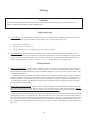
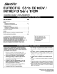
D E S I G N E D T O L E A D TWZ Series Oil-Fired Hot Water Boilers INSTALLATION INSTRUCTIONS These instructions must be affixed on or adjacent to the boiler Models: • TWZ065 • TWZ075 • TWZ100 • TWZ090 • TWZ125 • TWZ150 • TWZ120 • TWZ175 • TWZ200 WARNING: Improper installation, adjustment, alteration, service or maintenance can cause property damage, injury, or loss of life. For assistance or additional information, consult a qualified installer, service agency or the oil supplier. Read these instructions carefully before installing. Manufacturer of Hydronic Heating Products P.O. Box 14818 3633 I. Street Philadelphia, 1 PA 19134 7HO)D[ZZZFURZQERLOHUFRP Table of Contents I. Product Description ............................................................. 1 II. Specifications ....................................................................... 1 III. Before Installing ................................................................... 2 IV. Locating the Boiler ............................................................... 3 V. Air for Combustion & Ventilation ........................................ 5 VI. Venting .................................................................................. 9 VII. System Piping Connections ............................................... 11 VIII. Tankless Heater Piping ................................ 15 IX. Fuel Line Piping ........................................... 16 X. Wiring .......................................................... 19 XI. Start-up and Checkout .................................. 21 XII. Service & Maintenance ................................ 24 XIII. Parts ............................................................. 27 I Product Description The TWZ series boiler is a cast iron oil-fired water boiler designed for use in closed forced circulation heating systems. This boiler must be vented by natural draft into a lined masonry or metal chimney, or Type L vent. An adequate supply of air for combustion, ventilation and dilution of flue gases must be available in the boiler room. An optional tankless heater is available to generate domestic hot water. II Specifications SUPPLY PIPE LOCATION FIGURE 1: GENERAL CONFIGURATION * *Notes: 1. Tankless Coil Opening Not Present On Less-Coil Boilers. 2. Circulator Supplied Loose - May Be Installed On Supply Or Return. 21 TABLE 1a: GENERAL SPECIFICATIONS Boiler Model TWZ065 TWZ075 TWZ100 TWZ090 TWZ125 TWZ150 TWZ120 TWZ175 TWZ200 Number of Sections 3 3 3 4 4 4 5 5 5 Burner Input (Gal/hr) 0.65 0.75 1.00 0.90 1.25 1.50 1.20 1.75 2.00 DOE Heating Capacity (Btu/hr) 80000 91000 120000 111000 152000 179000 147000 210000 238000 Approx. Water I=B=R Net Rating (Btu/hr) AFUE (%) Content (Gal) 70000 86.1 16.0 79000 85.8 16.0 104000 84.3 16.0 97000 86.0 20.0 132000 84.9 20.0 156000 83.8 20.0 128000 86.0 24.0 183000 83.5 24.0 207000 83.3 24.0 Dimensions (inches) "A" "B" "C" 16 1/2 8 5/16 6 16 1/2 8 5/16 6 16 1/2 8 5/16 6 21 1/2 10 13/16 7 21 1/2 10 13/16 7 21 1/2 10 13/16 7 26 1/2 13 5/16 8 26 1/2 13 5/16 8 26 1/2 13 5/16 8 TABLE 1b: OPTIONAL TANKLESS HEATER RATINGS Boiler Model TWZ065 TWZ075 TWZ100 TWZ090 TWZ125 TWZ150 TWZ120 TWZ175 TWZ200 Tankless Heater Rating (Gal/min) 2.75 3.00 3.25 3.25 3.75 4.00 3.50 4.25 4.75 Notes: 1. 2. 3. Net Ratings are based on piping and pick-up allowances of 1.15. Burner Capacity Rating, GPH is based on #2 oil with a Gross Heating Value equal to 140000 BTU/Gal. Maximum Working Pressure, Water - 50 PSI. 4. Tankless Heater Ratings based on I=W=H test standard. III Before Installing 1) Safe, reliable operation of this boiler depends upon installation by a professional heating contractor in strict accordance with this manual and the requirements of the authority having jurisdiction. • In the absence of an authority having jurisdiction, installation must be in accordance with this manual and the latest edition of Installation of Oil Burning Equipment (ANSI/NFPA31). • Where required by the authority having jurisdiction, this installation must conform to the latest edition of Standard for Controls and Safety Devices for Automatically Fired Boilers (ANSI/ASME CSD-1). 2) Make sure that a properly sized chimney is available which is in good condition. Consult the authority having jurisdiction, Part VI of this manual, and ANSI/NFPA31 for additional information on venting requirements. Power (“Side Wall”) Venting - Important Note Two problems arise when any oil-fired appliance is power vented: 1. There is sometimes an accelerated rate of soot buildup on the oil burner cad-cell, spinner etc. 2. There is a potential for severe damage to the side of the structure in the event that the boiler operates at a high smoke level. This can happen for many reasons, some of which are out of the control of both the installer and appliance manufacturer. Crown Boiler Company recommends the use of a chimney to vent the TWZ series boilers. If a power venter must be used, it is the responsibility of the installer and power vent manufacturer to “engineer” the power vent system. CROWN BOILER COMPANY WILL ASSUME NO RESPONSIBILITY FOR DAMAGE TO SIDING, ETC. FROM A POWER VENTED OIL-FIRED BOILER. THIS APPLIES REGARDLESS OF THE CAUSE OF THE SOOTING. 32 3) Make sure that the boiler is correctly sized: • • • • For heating systems employing convection radiation (baseboard or radiators) use an industry accepted sizing method such as the I=B=R Heat Loss Calculation Guide (Pub. #H21 or #H22) published by the Hydronics Institute in Berkeley Heights, NJ. For new radiant heating systems refer to the radiant tubing manufacturer’s boiler sizing guidelines. For systems including a Crown Mega-Stor indirect water heater, size the boiler to have either the DOE Heating Capacity required for the Mega-Stor or the net rating required for the heating system, whichever results in the larger boiler. For systems that incorporate other indirect water heaters, refer to the indirect water heater manufacturer’s instructions for boiler output requirements. 4) In some cases, boilers installed at altitudes above 2000ft may require a different burner configuration from that at sea level. Consult the local Crown representative for more information. IV Locating the Boiler 1) Clearances: • Observe the minimum clearances shown below. Except as noted, these clearances apply to all combustible construction, as well as noncombustible walls, ceilings and doors. Also see Figure 2. Front – 24” Left Side – 6” Right Side – 6” Rear – 6” Top – 6” Single Wall Chimney Connector (to combustible construction) - 18” • A 24” service clearance from the jacket is recommended from the top of the boiler. This clearance may be reduced to that shown above; however, servicing the boiler will become increasingly difficult as this clearance is reduced. 2) If listed Type L vent is used, follow vent pipe manufacturer recommendations for minimum clearances. 3) Do not install this boiler directly on a combustible surface. Where it is desired to install the TWZ over a non-carpeted combustible surface, install the boiler on the base shown in Figure 3. 4) Do not install this boiler in a location where gasoline or other flammable vapors or liquids will be stored or used. Do not install this boiler in an area where large amounts of airborne dust will be present, such as a workshop. 43 18* 6 6 24 FRONTVIEW 6 SIDE VIEW * CLEARANCE FROM SINGLE WALL CONNECTOR TO COMBUSTIBLE CONSTRUCTION FIGURE 2: CLEARANCES 0.47" Sheet Metal (24 GA or Thicker) 4“ MIN. Combustible Surfac e Openings Aligned To Permit Free Air Circulation Hollow Masonry Blocks FIGURE 3: INSTALLATION OVER A COMBUSTIBLE FLOOR 54 V Air for Combustion and Ventilation Sufficient fresh air must be supplied for combustion and ventilation. Provisions for combustion and ventilation air for oil burning equipment must be made in accordance with Section 1.5, Air for Combustion and Ventilation, in the latest edition of Installation of Oil Burning Equipment (ANSI/NFPA 31). To ensure an adequate supply of air for combustion, ventilation and flue gas dilution, start by determining whether the boiler is to be installed in a building of unusually tight construction. A building of unusually tight construction is defined as having all of the following features: • Walls and ceilings exposed to outside atmosphere have a continuous water vapor retarder with a rating of 1 perm or less with openings gasketed and sealed • Weather stripping has been added on openable windows and doors • Caulking and sealants are applied to areas such as joints around window and door frames, between sole plates and floors, between wall-ceiling joints, between wall panels, at penetrations for plumbing, electrical, and gas lines, and at other openings. For Buildings of Other than Unusually Tight Construction 1) Determine whether the boiler is to be installed in a confined space - A confined space is defined as having a volume less than 50 cubic feet per 1000 BTU/hr input of all appliances installed in that space. To determine whether the boiler room is a confined space: a. b. c. Total the input of all appliances in the boiler room in thousands of BTU/hr. Round the result to the next highest 1000 BTU/hr. Find the volume of the room in cubic feet. The volume of the room in cubic feet is: Length (ft) x width (ft) x ceiling height (ft) In calculating the volume of the boiler room, consider the volume of adjoining spaces only if no doors are installed between them. If doors are installed between the boiler room and an adjoining space, do not consider the volume of the adjoining space, even if the door is normally left open. Divide the volume of the boiler room by the input in thousands of BTU/hr. If the result is less than 50, the boiler room is a confined space. Example: A TWZ090 and a water heater are to be installed in a room measuring 6 ft - 3 in x 7 ft with an 8 ft ceiling. The water heater has an input of 30000 BTU/hr: Input of TWZ090 = 0.90 Gal/hr x 140000 BTU/Gal = 126000 BTU/hr Total input in thousands of BTU/hr = (126000 BTU/hr + 30000 BTU/hr)/1000 = 156 Volume of room = 6.25 ft x 7 ft x 8 ft = 350 ft3 350/156 = 2.24. Since 2.24 is less than 50, the boiler room is a confined space. 2) Unconfined Space - Natural infiltration into the boiler room will normally provide adequate air for combustion and ventilation without additional louvers or openings into boiler room. 3) Confined Space - Provide two openings into the boiler room, one near the floor and one near the ceiling. The top edge of the upper opening must be within 12” of the ceiling and the bottom edge of the lower opening must be within 12” of the floor (Figure 4). • • • Each opening must have a free area of 1 square inch per 1000 BTU/hr input of all fuel burning appliances in the boiler room. The minimum opening dimension is 3 inches. Minimum opening free area is 100 square inches per opening. If the total volume of both the boiler room and the room to which the openings connect is less than 50 cubic feet per 1000 BTU/hr of total appliance input, install a pair of identical openings into a third room. Connect additional rooms with openings until the total volume of all rooms is at least 50 cubic feet per 1000 BTU/hr of input. The “free area” of an opening takes into account the blocking effect of mesh, grills, and louvers. Where screens are 65 FIGURE 4: BOILER INSTALLED IN CONFINED SPACE, ALL AIR FROM INSIDE used, they must be no finer than ¼” (4 x 4) mesh. For Buildings of Unusually Tight Construction: 1) Openings must be installed between the boiler room and the outdoors or a ventilated space, such as an attic or crawl space, which communicates directly with the outdoors. 2) Two openings are required. The top edge of the upper opening must be within 12 inches of the ceiling. The bottom edge of the lower opening must be within 12 inches of the floor. 3) Size openings and ducts as follows: • Vertical ducts or openings directly outdoors (Figure 5, Figure 6, and Figure 7) - Each opening must have a free cross sectional area of 1 square inch per 4000 BTU/hr of the total input of all fuel fired appliances in the boiler room but not less than 100 square inches. Minimum opening size is 3 inches. • Openings to outdoors via horizontal ducts (Figure 8) - Each opening must have a free cross sectional area of 1 square inch per 2000 BTU/hr of the total input of all fuel fired appliances in the boiler room but not less than 100 square inches. Minimum opening size is 3 inches. • The “free area” of an opening takes into account the blocking effect of mesh, grills, and louvers. Where screens are used, they must be no finer than ¼” (4 x 4) mesh. 76 FIGURE 5: ALL AIR FROM OUTDOORS, VENTILATED CRAWL SPACE AND ATTIC FIGURE 6: ALL AIR FROM OUTDOORS, VIA VENTILATED ATTIC 87 FIGURE 7: ALL AIR FROM OUTDOORS, USING OPENINGS INTO BOILER ROOM FIGURE 8: ALL AIR FROM OUTDOORS, USING HORIZONTAL DUCTS INTO BOILER ROOM 98 VI Venting Vent installation must be in accordance with local building codes, or the local authority having jurisdiction. Typical vent installation is illustrated by Figure 9. The components of vent installation are the vent connector (breeching), barometric draft regulator, and chimney. 1) Acceptable Chimneys - The following chimneys may be used to vent a TWZ series boiler: • Listed Type L vent - Install in accordance with the manufacturer’s instructions, the terms of its listing, and applicable codes. • Masonry Chimney - The masonry chimney must be constructed in accordance with the latest edition of Standard for Chimneys, Fireplaces, Vents, and Solid Fuel Burning Appliances (NFPA 211) and lined with a clay liner or other listed lining system. Do not vent a TWZ series boiler into an unlined chimney. 2) Acceptable Vent Connectors - The following may be used for vent connectors: • Listed Type L vent. • Single Wall Galvanized Pipe - Use 0.018” (26 gauge) or heavier. FIGURE 9: TYPICAL VENT SYSTEM INSTALLATION AND COMPONENTS 3) Chimney and Vent Connector Sizing - See Table 2 for minimum vent connector and chimney sizing. The vent connector size must not be smaller than boiler flue collar diameter. Where two or more appliances vent into a common vent, the cross-sectional area of the common vent should at least equal the area of largest vent plus 50% of the area in the additional vents. 4) Do not vent this appliance into any portion of a mechanical vent system operating under positive pressure. 5) Do not connect the boiler into a chimney flue serving an open fireplace or other solid fuel appliance. 9 10 6) Prior to boiler installation, inspect chimney for obstructions or other defects and correct as required. Clean chimney as necessary. 7) Vent pipe should slope upward from boiler not less than one inch in four feet. No portion of vent pipe should run downward or have sags. Vent pipe must be securely supported. 8) The vertical section of vent pipe coming off the boiler should be as tall as possible, while still maintaining the proper clearance from the horizontal vent connector to combustibles and the proper pitch called for in (7) above. 9) Vent pipe should be installed above the bottom of the chimney to prevent blockage. 10) Vent pipe must be inserted flush with inside face of the chimney liner and the space between vent pipe and chimney sealed tight. A thimble permanently cemented in place can be used to facilitate removal of chimney connector for cleaning. 11) Install the barometric draft regulator in accordance with the regulator manufacturer’s instructions. 12) Secure all joints in the vent connector system with sheet metal screws. This includes the joint between the vent connector and the boiler collar, as well as the barometric draft regulator. Use at least three screws at each joint. TABLE 2: MINIMUM RECOMMENDED BREECHING AND CHIMNEY SIZE Boiler Min Breeching Model Dia. (inches) TWZ065 6 TWZ075 6 TWZ100 6 TWZ090 7 TWZ125 7 TWZ150 7 TWZ120 8 TWZ175 8 TWZ200 8 Min. Recommended Chimney Size and Height Round I.D. (in) Rectangular I.D. (in) Height (ft) 6 8x8 15 6 8x8 15 6 8x8 15 7 8x8 15 7 8x8 15 7 8x8 15 8 8x8 15 8 8x8 15 8 8x8 15 Power (“Side Wall”) Venting - Important Note Two problems arise when any oil-fired appliance is power vented: 1. There is sometimes an accelerated rate of soot buildup on the oil burner cad-cell, spinner etc. 2. There is a potential for severe damage to the side of the structure in the event that the boiler operates at a high smoke level. This can happen for many reasons, some of which are out of the control of both the installer and appliance manufacturer. Crown Boiler Company recommends the use of a chimney to vent the TWZ series boilers. If a power venter must be used, it is the responsibility of the installer and power vent manufacturer to “engineer” the power vent system. CROWN BOILER COMPANY WILL ASSUME NO RESPONSIBILITY FOR DAMAGE TO SIDING, ETC. FROM A POWER VENTED OIL-FIRED BOILER. THIS APPLIES REGARDLESS OF THE CAUSE OF THE SOOTING. 10 11 VII System Piping CAUTION • INSTALL BOILER SO THAT ALL ELECTRICAL COMPONENTS ARE PROTECTED FROM WATER (DRIPPING, SPRAYING, RAIN, ETC.) DURING APPLIANCE OPERATION AND SERVICE (CIRCULATOR REPLACEMENT, ETC.). • OPERATION OF THIS BOILER WITH CONTINUOUS RETURN TEMPERATURES BELOW 120°F CAN CAUSE SEVERE HEAT EXCHANGER CORROSION DAMAGE. • OPERATION OF THIS BOILER IN A SYSTEM HAVING SIGNIFICANT AMOUNTS OF DISSOLVED OXYGEN CAN CAUSE SEVERE HEAT EXCHANGER CORROSION DAMAGE. • DO NOT USE TOXIC ADDITIVES, SUCH AS AUTOMOTIVE ANTIFREEZE, IN A HYDRONIC SYSTEM. Standard Piping Figure 10 shows typical boiler system connections on a single zone system. Additional information on hydronic system design may be found in Installation of Residential Hydronic Systems (Pub. #200) published by the Hydronics Institute in Berkeley Heights, NJ. The components in this system and their purposes are as follows: 1) Relief valve (Required) - Mount the relief valve on the top left side of the boiler as shown in Figure 10 using the 3/4” nipple provided. The relief valve shipped with the boiler is set to open at 30 psi. This valve may be replaced with one having a pressure up to the “Maximum Allowable Working Pressure” shown on the rating plate. If the valve is replaced, the replacement must have a relief capacity in excess of the DOE heating capacity for the boiler. Pipe the discharge of the relief valve to a location where water or steam will not create a hazard or cause property damage if the valve opens. The end of the discharge pipe must terminate in an unthreaded pipe. If the relief valve discharge is not piped to a drain, it must terminate at least 6 inches above the floor. Do not run relief valve discharge piping through an area that is prone to freezing. The termination of the relief valve discharge piping must be in an area where it is not likely to become plugged by debris. FIGURE 10: STANDARD BOILER PIPING 11 12 DANGER • • • • PIPE RELIEF VALVE TO A SAFE LOCATION DO NOT INSTALL A VALVE IN THE RELIEF VALVE DISCHARGE LINE DO NOT MOVE RELIEF VALVE FROM FACTORY SPECIFIED LOCATION DO NOT PLUG RELIEF VALVE DISCHARGE 2) Circulator (Required) - Figure 10 shows the ideal location of the circulator which is in the supply piping immediately downstream of the expansion tank. A less ideal, but acceptable, location for most residential circulators is in the return (if this is done, be sure that adequate clearance exists to open the door. 3) Expansion Tank (Required) - If this boiler is replacing an existing boiler with no other changes in the system, the old expansion tank can generally be reused. If the expansion tank must be replaced, consult the expansion tank manufacturer’s literature for proper sizing. 4) Fill Valve (Required) - Either a manual or automatic fill valve may be used. The ideal location for the fill is at the expansion tank. 5) Automatic Air Vent (Required) - At least one automatic air vent is required. Manual vents will usually be required in other parts of the system to remove air during initial fill. 6) Low Water Cut-Off (Required in some situations) - A low water cut-off is required when the boiler is installed above radiation. In addition, some codes such as ASME CSD-1 require low water cut-offs. Codes may also require that this low water cut-off have a manual reset function. The low water cut-off may be a float type or probe type, but must be designed for use in a hot-water system. The low water cut-off should be piped into the boiler supply just above the boiler with no intervening valves between it and the boiler. Use a low water cut-off that breaks the 120 VAC supply to the boiler. Do not attempt to wire a 24-volt low water cutoff into the boiler factory wiring. 7) Manual Reset High Limit (Required by some codes) - This control is required by ASME CSD-1 and some other codes. Install the high limit in the boiler supply piping just beyond the boiler with no intervening valves. Set the manual reset high limit as far above the operating limit setting as possible, but not over 240°F. Wire the control to break the 120 VAC electrical supply to the boiler. 8) Flow Control Valve (Required under some conditions) - The flow control valve prevents flow through the system unless the circulator is operating. A flow control valve may be necessary on converted gravity systems to prevent gravity circulation. Flow control valves are also used to prevent “ghost flows” in circulator zone systems through zones that are not calling for heat. 9) Isolation Valves (Optional) - Isolation valves are useful if the boiler must be drained, as they will eliminate having to drain and refill the entire system. 10) Drain Valve - The drain valve is shipped in the boiler parts bag. Install it in the tee on the boiler return as shown in Figure 1. IMPORTANT THE 1 1/2” PLUGGED TAPPING ON THE BOTTOM REAR SECTION IS PRESENT FOR MANUFACTURING PURPOSES ONLY. DO NOT ATTEMPT TO USE THIS TAPPING AS A RETURN CONNECTION. 12 13 FIGURE 11: INDIRECT WATER HEATER BOILER SIDE PIPING FIGURE 12: BOILER BYPASS PIPING Piping for Special Situations Certain types of heating systems have additional requirements. Some of the more common variations follow: 1) Indirect Water Heaters - Figure 11 shows typical indirect water heater piping. Boiler piping is the same as for any twozone system. Figure 11 shows circulator zoning, which is usually preferred for indirect water heaters. Size the circulator and indirect water heater piping to obtain the boiler water flow through the indirect water heater called for by the indirect water heater manufacturer. 2) Large Water Volume Systems - The piping shown in Figure 12 will minimize the amount of time that the boiler operates with return temperatures below 120°F on these systems. A bypass is installed as shown to divert some supply water directly into the return water. The bypass pipe should be the same size as the supply. The two throttling valves shown are adjusted so that the return temperature rises above 120°F during the first few minutes of operation. A three-way valve can be substituted for the two throttling valves shown. 13 14 3) Low Temperature Systems - Some systems, such as radiant tubing systems, require the system water temperature to be limited to a value below the temperature of the water leaving the TWZ. These systems also typically have return temperatures well below the 120°F minimum. Figure 13 illustrates the use of a heat exchanger to connect the TWZ boiler to this type of system. The heat exchanger will permit the transfer of heat from the boiler water to the low temperature system while holding the system supply and boiler return temperatures within their limits. For this system to work properly, the heat exchanger must be properly sized and the correct flow rates are required on either side of the heat exchanger. Consult the heat exchanger manufacturer for sizing information. The water in the boiler is completely isolated from the water in the system. This means that separate fill and expansion tanks are required for the heating system loop. There are several other ways to connect low temperature systems to the non-condensing boilers like the TWZ such as four way mixing valves and variable speed injection pumping systems. 4) Systems containing oxygen - Many hydronic systems contain enough dissolved oxygen to cause severe corrosion damage to a cast iron boiler such as the TWZ. Some examples include: • Radiant systems that employ tubing without an oxygen barrier. • Systems with routine additions of fresh water. • Systems which are open to the atmosphere. If the boiler is to be used in such a system, it must be separated from the oxygenated water being heated with a heat exchanger as shown in Figure 13. Consult the heat exchanger manufacturer for proper heat exchanger sizing as well as flow and temperature requirements. All components on the oxygenated side of the heat exchanger, such as the pump and expansion tank, must be designed for use in oxygenated water. 5) Air Handlers - Where the boiler is connected to air handlers through which refrigerated air passes, use flow control valves in the boiler piping or other automatic means to prevent gravity circulation during the cooling cycle. FIGURE 13: ISOLATION OF BOILER FROM SYSTEM WITH A HEAT EXCHANGER 14 15 VIII TANKLESS HEATER PIPING If the TWZ is installed with an optional tankless heater, pipe the heater as shown in Figure 14. The components in this system and their functions are as follows: 1) Mixing Valve (Required) - During the heating season, the water exiting the tankless heater may be 180 degrees or more. The mixing valve blends hot water leaving the tankless heater with cold water so as to maintain the hot water supplied to the fixtures at a fixed temperature. This saves energy, increases the amount of usable hot water available to the homeowner, and reduces the risk of scalding. Install a mixing valve with a setting range of approximately 110 to 130F. Follow the manufacturer’s instructions for installing this valve. Usually a “heat trap” will be required between the coil and the “hot” connection on the mixing valve. WARNING A mixing valve does not eliminate the risk of scalding. • Set the mixing valve and boiler low limit adjustments as low as possible. • Feel water before showering or bathing. • If anti-scald or anti-chill protection is required, use devices specifically designed for such service. Install and maintain these devices in accordance with the manufacturer’s instructions. Do not use the mixing valve as a substitute for pressure balancing valves or other devices required by plumbing codes to protect against scalding. 2) Flow Restrictor (Recommended) - If water is drawn from the tankless coil at a rate in excess of the rating in Table 1b, the temperature of the hot water may be too low to be of use. The use of a flow restrictor will prevent this problem by limiting the rate at which water can pass through the tankless heater. If a restrictor is used, select one having a rating in GPM approximately equal to the rating shown in Table 1b. If possible, locate this restrictor at least 3 feet from the tankless heater inlet so that it is not subjected to excessive temperatures when no water is flowing through the coil. 3) Pressure Relief Valve (Required) - Limits the pressure in the tankless heater and piping. Use an ASME constructed valve designed for domestic water service, such as the Watts #3L. Note that this is a pressure relief valve, not a T&P valve. Select a valve with a pressure setting less than or equal to the working pressure marked on the tankless coil. Pipe the discharge to a safe location using piping the same size as the discharge connection on the valve. 4) Hose Bib Valves (Recommended) - These valves permit the coil to be periodically “backflushed” to remove sediment. 5) Globe or Ball Valve (Recommended) - Used to adjust the flow through the entire tankless heater system if needed. 6) Unions (Required) - Tankless heaters may require periodic gasket replacement or other maintenance which requires removal of the heater from the boiler. Install unions anywhere in the tankless heater piping that will facilitate removal of the heater. 15 16 FIGURE 14: TANKLESS HEATER PIPING IX Fuel Line Piping Fuel line piping design, materials and construction must be in accordance with local building codes, requirements of the local authority having jurisdiction, and, the latest edition of Installation of Oil-Burning Equipment (ANSI/NFPA 31). Refer also to the instruction manuals provided with the burner and oil pump. Depending on the location of the fuel oil storage tank in relation to an oil burner, there are four types of oil piping systems generally being used: a) ONE-PIPE GRAVITY SYSTEM - used when a fuel oil storage tank is positioned above an oil burner fuel pump. See Figure 15. A vertical distance from top of the tank to center line of the pump (Dimension ‘H’) over 8 feet will result in a pump inlet pressure in excess of the 3-psi limit in NFPA-31. FIGURE 15: ONE-PIPE GRAVITY SYSTEM 16 17 b) ONE-PIPE LIFT SYSTEM (not recommended) - Used when a fuel oil storage tank is located below an oil burner fuel pump. See Figure 16. The vertical distance from bottom of the tank to center line of the pump (Dimension ‘H’) must not exceed that shown in the pump manufacturer’s instructions. Although all oil piping systems must be airtight, one-pipe lift systems are particularly susceptible to nuisance lockout problems if the suction line is not completely airtight. A two-pipe lift system is therefore recommended over a one-pipe lift system. c) TWO-PIPE GRAVITY SYSTEM (not recommended) - Used when a fuel oil storage tank is located above an oil burner fuel pump. See Figure 17. A vertical distance from top of the tank to center line of the pump (Dimension ‘H’) over 8 feet will result in a pump inlet pressure in excess of the 3-psi limit in NFPA-31. This type of system should be converted to a one-pipe gravity system, as doing so will result in lower inlet line flow and longer filter life. d) TWO-PIPE LIFT SYSTEM - used when a fuel oil storage tank is located below an oil burner fuel pump suction port. See Figure 18. The vertical distance from bottom of the tank to center line of the pump (Dimension ‘H’) must not exceed that shown in the pump manufacturer’s instructions. Distance ‘H’ allowed is reduced by the number of fittings, filters and valves installed in the line. Once the type of system has been selected, observe the following: 1) Fuel line piping must be airtight. Do not use compression type fittings for tubing connections in fuel line piping. Use only listed flare type fittings. Cast iron threaded fittings shall not be used for wrought iron or steel piping connections. 2) Piping shall be substantially supported and protected against physical damage and corrosion where required. 3) Refer to supplied oil pump instruction manual for proper connections. On one-pipe systems, ensure that the fuel pump return port plug is tightened securely. 4) Some fuel pumps, such as the Suntec A and B series, are supplied with a loose bypass plug which must be installed on two-pipe systems. If such a plug is supplied, install it as shown in the pump manufacturer’s instructions. Do not install this bypass plug on one-pipe systems as pump seal damage will result. 5) Do not use check valves, especially on gravity feed systems. 6) Do not use Teflon tape for threaded connections. Use a listed non-hardening thread sealant instead. 7) Attach required piping between burner fuel pump and fuel oil storage tank. Install one fuel shut-off valve near the storage tank and second fuel shut-off valve near the oil burner fuel pump. Use heavy wall copper tubing in a continuous run. On two-pipe systems, the return line should terminate 3” - 4” above suction line depth within the storage tank. Refer to the pump manufacturer’s instructions for tube sizing information. 8) All systems require an oil filter. On TWZ065 and TWZ075 boilers, the use of a Garber cartridge type filter is recommended. 9) Use only #2 Fuel Oil with physical and chemical characteristics meeting the requirements of ASTM D-396. FIGURE 16: ONE-PIPE LIFT SYSTEM 17 18 FIGURE 17: TWO-PIPE GRAVITY FEED SYSTEM FIGURE 18: TWO-PIPE LIFT SYSTEM 18 19 X Wiring WARNING All wiring and grounding must be done in accord