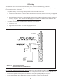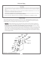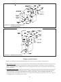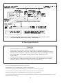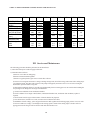
1
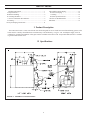
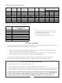
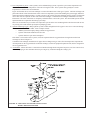
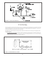
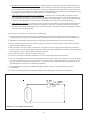
TWZ Series
Oil-Fired Hot Water Boilers
INSTALLATION INSTRUCTIONS
These instructions must be affixed on or adjacent to the boiler
Models:
• TWZ065
• TWZ075
• TWZ100
• TWZ090
• TWZ125
• TWZ150
• TWZ120
• TWZ175
• TWZ200
WARNING: Improper installation,
adjustment, alteration, service or
maintenance can cause property
damage, injury, or loss of life.
For assistance or additional
information, consult a qualified
installer, service agency or the
oil supplier. Read these instructions carefully before installing.
CROWN
Boiler Co
Manufacturer of Hydronic Heating Products
P.O. Box 14818 3633 I. Street
Philadelphia, PA 19134
1
Tel: (215) 535-8900 • Fax: (215) 535-9736
• www.crownboiler.com
Table of Contents
I. Product Description .............................................................. 1
II. Specifications ........................................................................ 1
III. Before Installing ................................................................... 2
IV. Locating the Boiler ................................................................ 3
V. Air for Combustion & Ventilation ......................................... 5
VI. Venting .................................................................................. 9
VII. System Piping Connections ................................................ 11
VIII. Tankless Heater Piping ................................. 15
IX. Fuel Line Piping ........................................... 16
X. Wiring ........................................................... 19
XI. Start-up and Checkout .................................. 21
XII. Service & Maintenance ................................ 24
XIII. Parts .............................................................. 27
I Product Description
The TWZ series boiler is a cast iron oil-fired water boiler designed for use in closed forced circulation heating systems. This
boiler must be vented by natural draft into a lined masonry or metal chimney, or Type L vent. An adequate supply of air for
combustion, ventilation and dilution of flue gases must be available in the boiler room. An optional tankless heater is available
to generate domestic hot water.
II Specifications
FIGURE 1: GENERAL CONFIGURATION
21
TABLE 1a: GENERAL SPECIFICATIONS
Boiler Model
TWZ065
TWZ075
TWZ100
TWZ090
TWZ125
TWZ150
TWZ120
TWZ175
TWZ200
Number of
Sections
3
3
3
4
4
4
5
5
5
Burner
Input
(Gal/hr)
0.65
0.75
1.00
0.90
1.25
1.50
1.20
1.75
2.00
DOE Heating
Capacity
(Btu/hr)
80000
91000
120000
111000
152000
179000
147000
210000
238000
I=B=R Net
Approx. Water
Rating (Btu/hr) AFUE (%) Content (Gal)
70000
86.1
16.0
79000
85.8
16.0
104000
84.3
16.0
97000
86.0
20.0
132000
84.9
20.0
156000
83.8
20.0
128000
86.0
24.0
183000
83.5
24.0
207000
83.3
24.0
Dimensions (inches)
"A"
"B"
"C"
16 1/2
8 5/16
6
16 1/2
8 5/16
6
16 1/2
8 5/16
6
21 1/2
10 13/16
7
21 1/2
10 13/16
7
21 1/2
10 13/16
7
26 1/2
13 5/16
8
26 1/2
13 5/16
8
26 1/2
13 5/16
8
TABLE 1b: OPTIONAL TANKLESS HEATER RATINGS
Boiler Model
TWZ065
TWZ075
TWZ100
TWZ090
TWZ125
TWZ150
TWZ120
TWZ175
TWZ200
Tankless Heater Rating
(Gal/min)
2.75
3.00
3.25
3.25
3.75
4.00
3.50
4.25
4.75
Notes:
1. Net Ratings are based on piping and pick-up allowances of 1.15.
2. Burner Capacity Rating, GPH is based on #2 oil with a Gross
Heating Value equal to 140000 BTU/Gal.
3. Maximum Working Pressure, Water - 50 PSI.
4.
Tankless Heater Ratings based on I=W=H test standard.
III Before Installing
1) Safe, reliable operation of this boiler depends upon installation by a professional heating contractor in strict accordance
with this manual and the requirements of the authority having jurisdiction.
•
In the absence of an authority having jurisdiction, installation must be in accordance with this manual and the latest
edition of Installation of Oil Burning Equipment (ANSI/NFPA31).
•
Where required by the authority having jurisdiction, this installation must conform to the latest edition of Standard for
Controls and Safety Devices for Automatically Fired Boilers (ANSI/ASME CSD-1).
2) Make sure that a properly sized chimney is available which is in good condition. Consult the authority having
jurisdiction, Part VI of this manual, and ANSI/NFPA31 for additional information on venting requirements.
Power (“Side Wall”) Venting - Important Note
Two problems arise when any oil-fired appliance is power vented:
1. There is sometimes an accelerated rate of soot buildup on the oil burner cad-cell, spinner etc.
2. There is a potential for severe damage to the side of the structure in the event that the boiler operates at a high smoke level.
This can happen for many reasons, some of which are out of the control of both the installer and appliance manufacturer.
Crown Boiler Company recommends the use of a chimney to vent the TWZ series boilers. If a power venter must be used, it
is the responsibility of the installer and power vent manufacturer to “engineer” the power vent system. CROWN BOILER
COMPANY WILL ASSUME NO RESPONSIBILITY FOR DAMAGE TO SIDING, ETC. FROM A POWER
VENTED OIL-FIRED BOILER. THIS APPLIES REGARDLESS OF THE CAUSE OF THE SOOTING.
32
3) Make sure that the boiler is correctly sized:
•
•
•
•
For heating systems employing convection radiation (baseboard or radiators) use an industry accepted sizing
method such as the I=B=R Heat Loss Calculation Guide (Pub. #H21 or #H22) published by the Hydronics
Institute in Berkeley Heights, NJ.
For new radiant heating systems refer to the radiant tubing manufacturer’s boiler sizing guidelines.
For systems including a Crown Mega-Stor indirect water heater, size the boiler to have either the DOE Heating
Capacity required for the Mega-Stor or the net rating required for the heating system, whichever results in the
larger boiler.
For systems that incorporate other indirect water heaters, refer to the indirect water heater manufacturer’s
instructions for boiler output requirements.
4) In some cases, boilers installed at altitudes above 2000ft may require a different burner configuration from that at sea level.
Consult the local Crown representative for more information.
IV Locating the Boiler
1) Clearances:
•
Observe the minimum clearances shown below. Except as noted, these clearances apply to all combustible
construction, as well as noncombustible walls, ceilings and doors. Also see Figure 2.
Front – 24”
Left Side – 6”
Right Side – 6”
Rear – 6”
Top – 6”
Single Wall Chimney Connector (to combustible construction) - 18”
•
A 24” service clearance from the jacket is recommended from the top of the boiler. This clearance may be
reduced to that shown above; however, servicing the boiler will become increasingly difficult as this clearance is
reduced.
2) If listed Type L vent is used, follow vent pipe manufacturer recommendations for minimum clearances.
3) Do not install this boiler directly on a combustible surface. Where it is desired to install the TWZ over a non-carpeted
combustible surface, install the boiler on the base shown in Figure 3.
4) Do not install this boiler in a location where gasoline or other flammable vapors or liquids will be stored or used. Do not
install this boiler in an area where large amounts of airborne dust will be present, such as a workshop.
43
18*
6
6
24
FRONT VIEW
6
SIDE VIEW
* CLEARANCE FROM SINGLE WALL CONNECTOR TO COMBUSTIBLE CONSTRUCTION
FIGURE 2: CLEARANCES
0.47"
Sheet Metal (24 GA or Thicker)
4“ MIN.
Combustible Surface
Openings Aligned To Permit Free Air Circulation
Hollow Masonry Blocks
FIGURE 3: INSTALLATION OVER A COMBUSTIBLE FLOOR
54
V Air for Combustion and Ventilation
Sufficient fresh air must be supplied for combustion and ventilation. Provisions for combustion and ventilation air for oil
burning equipment must be made in accordance with Section 1.5, Air for Combustion and Ventilation, in the latest edition of
Installation of Oil Burning Equipment (ANSI/NFPA 31).
To ensure an adequate supply of air for combustion, ventilation and flue gas dilution, start by determining whether the boiler
is to be installed in a building of unusually tight construction. A building of unusually tight construction is defined as having
all of the following features:
• Walls and ceilings exposed to outside atmosphere have a continuous water vapor retarder with a rating of 1 perm or
less with openings gasketed and sealed
• Weather stripping has been added on openable windows and doors
• Caulking and sealants are applied to areas such as joints around window and door frames, between sole plates and
floors, between wall-ceiling joints, between wall panels, at penetrations for plumbing, electrical, and gas lines, and at
other openings.
For Buildings of Other than Unusually Tight Construction
1) Determine whether the boiler is to be installed in a confined space - A confined space is defined as having a volume less
than 50 cubic feet per 1000 BTU/hr input of all appliances installed in that space. To determine whether the boiler room is a
confined space:
a.
b.
c.
Total the input of all appliances in the boiler room in thousands of BTU/hr. Round the result to the next highest
1000 BTU/hr.
Find the volume of the room in cubic feet. The volume of the room in cubic feet is:
Length (ft) x width (ft) x ceiling height (ft)
In calculating the volume of the boiler room, consider the volume of adjoining spaces only if no doors are installed
between them. If doors are installed between the boiler room and an adjoining space, do not consider the volume of
the adjoining space, even if the door is normally left open.
Divide the volume of the boiler room by the input in thousands of BTU/hr. If the result is less than 50, the boiler
room is a confined space.
Example:
A TWZ090 and a water heater are to be installed in a room measuring 6 ft - 3 in x 7 ft with an 8 ft ceiling. The
water heater has an input of 30000 BTU/hr:
Input of TWZ090 = 0.90 Gal/hr x 140000 BTU/Gal = 126000 BTU/hr
Total input in thousands of BTU/hr = (126000 BTU/hr + 30000 BTU/hr)/1000 = 156
Volume of room = 6.25 ft x 7 ft x 8 ft = 350 ft3
350/156 = 2.24. Since 2.24 is less than 50, the boiler room is a confined space.
2) Unconfined Space - Natural infiltration into the boiler room will normally provide adequate air for combustion and
ventilation without additional louvers or openings into boiler room.
3) Confined Space - Provide two openings into the boiler room, one near the floor and one near the ceiling. The top edge of
the upper opening must be within 12” of the ceiling and the bottom edge of the lower opening must be within 12” of the floor
(Figure 4).
•
•
•
Each opening must have a free area of 1 square inch per 1000 BTU/hr input of all fuel burning appliances in the boiler
room. The minimum opening dimension is 3 inches. Minimum opening free area is 100 square inches per opening.
If the total volume of both the boiler room and the room to which the openings connect is less than 50 cubic feet per
1000 BTU/hr of total appliance input, install a pair of identical openings into a third room. Connect additional rooms
with openings until the total volume of all rooms is at least 50 cubic feet per 1000 BTU/hr of input.
The “free area” of an opening takes into account the blocking effect of mesh, grills, and louvers. Where screens are
used, they must be no finer than ¼” (4 x 4) mesh.
65
FIGURE 4: BOILER INSTALLED IN CONFINED SPACE,
ALL AIR FROM INSIDE
For Buildings of Unusually Tight Construction:
1) Openings must be installed between the boiler room and the outdoors or a ventilated space, such as an attic or crawl
space, which communicates directly with the outdoors.
2) Two openings are required. The top edge of the upper opening must be within 12 inches of the ceiling. The bottom
edge of the lower opening must be within 12 inches of the floor.
3) Size openings and ducts as follows:
• Vertical ducts or openings directly outdoors (Figure 5, Figure 6, and Figure 7) - Each opening must have a free
cross sectional area of 1 square inch per 4000 BTU/hr of the total input of all fuel fired appliances in the boiler
room but not less than 100 square inches. Minimum opening size is 3 inches.
• Openings to outdoors via horizontal ducts (Figure 8) - Each opening must have a free cross sectional area of 1
square inch per 2000 BTU/hr of the total input of all fuel fired appliances in the boiler room but not less than 100
square inches. Minimum opening size is 3 inches.
• The “free area” of an opening takes into account the blocking effect of mesh, grills, and louvers. Where screens
are used, they must be no finer than ¼” (4 x 4) mesh.
76
FIGURE 5: ALL AIR FROM OUTDOORS,
VENTILATED CRAWL SPACE AND ATTIC
FIGURE 6: ALL AIR FROM OUTDOORS,
VIA VENTILATED ATTIC
87
FIGURE 7: ALL AIR FROM OUTDOORS, USING
OPENINGS INTO BOILER ROOM
FIGURE 8: ALL AIR FROM OUTDOORS, USING
HORIZONTAL DUCTS INTO BOILER ROOM
98
VI Venting
Vent installation must be in accordance with local building codes, or the local authority having jurisdiction.
Typical vent installation is illustrated by Figure 9. The components of vent installation are the vent connector (breeching),
barometric draft regulator, and chimney.
1) Acceptable Chimneys - The following chimneys may be used to vent a TWZ series boiler:
•
Listed Type L vent - Install in accordance with the manufacturer’s instructions, the terms of its listing, and applicable
codes.
•
Masonry Chimney - The masonry chimney must be constructed in accordance with the latest edition of Standard for
Chimneys, Fireplaces, Vents, and Solid Fuel Burning Appliances (NFPA 211) and lined with a clay liner or other
listed lining system. Do not vent a TWZ series boiler into an unlined chimney.
2) Acceptable Vent Connectors - The following may be used for vent connectors:
•
Listed Type L vent.
•
Single Wall Galvanized Pipe - Use 0.018” (26 gauge) or heavier.
FIGURE 9: TYPICAL VENT SYSTEM
INSTALLATION AND COMPONENTS
3) Chimney and Vent Connector Sizing - See Table 2 for minimum vent connector and chimney sizing. The vent connector
size must not be smaller than boiler flue collar diameter. Where two or more appliances vent into a common vent, the crosssectional area of the common vent should at least equal the area of largest vent plus 50% of the area in the additional vents.
4) Do not vent this appliance into any portion of a mechanical vent system operating under positive pressure.
5) Do not connect the boiler into a chimney flue serving an open fireplace or other solid fuel appliance.
9
10
6) Prior to boiler installation, inspect chimney for obstructions or other defects and correct as required. Clean chimney as
necessary.
7) Vent pipe should slope upward from boiler not less than one inch in four feet. No portion of vent pipe should run
downward or have sags. Vent pipe must be securely supported.
8) The vertical section of vent pipe coming off the boiler should be as tall as possible, while still maintaining the proper
clearance from the horizontal vent connector to combustibles and the proper pitch called for in (7) above.
9) Vent pipe should be installed above the bottom of the chimney to prevent blockage.
10) Vent pipe must be inserted flush with inside face of the chimney liner and the space between vent pipe and chimney
sealed tight. A thimble permanently cemented in place can be used to facilitate removal of chimney connector for cleaning.
11) Install the barometric draft regulator in accordance with the regulator manufacturer’s instructions.
12) Secure all joints in the vent connector system with sheet metal screws. This includes the joint between the vent connector
and the boiler collar, as well as the barometric draft regulator. Use at least three screws at each joint.
TABLE 2: MINIMUM RECOMMENDED BREECHING AND
CHIMNEY SIZE
Boiler
Min Breeching
Model
Dia. (inches)
TWZ065
6
TWZ075
6
TWZ100
6
TWZ090
7
TWZ125
7
TWZ150
7
TWZ120
8
TWZ175
8
TWZ200
8
Min. Recommended Chimney Size and Height
Round I.D. (in) Rectangular I.D. (in)
Height (ft)
6
8x8
15
6
8x8
15
6
8x8
15
7
8x8
15
7
8x8
15
7
8x8
15
8
8x8
15
8
8x8
15
8
8x8
15
Power (“Side Wall”) Venting - Important Note
Two problems arise when any oil-fired appliance is power vented:
1. There is sometimes an accelerated rate of soot buildup on the oil burner cad-cell, spinner etc.
2. There is a potential for severe damage to the side of the structure in the event that the boiler operates at a high smoke level.
This can happen for many reasons, some of which are out of the control of both the installer and appliance manufacturer.
Crown Boiler Company recommends the use of a chimney to vent the TWZ series boilers. If a power venter must be used, it
is the responsibility of the installer and power vent manufacturer to “engineer” the power vent system. CROWN BOILER
COMPANY WILL ASSUME NO RESPONSIBILITY FOR DAMAGE TO SIDING, ETC. FROM A POWER
VENTED OIL-FIRED BOILER. THIS APPLIES REGARDLESS OF THE CAUSE OF THE SOOTING.
10
11
VII System Piping
CAUTION
• INSTALL BOILER SO THAT ALL ELECTRICAL COMPONENTS ARE PROTECTED FROM WATER (DRIPPING,
SPRAYING, RAIN, ETC.) DURING APPLIANCE OPERATION AND SERVICE (CIRCULATOR REPLACEMENT,
ETC.).
• OPERATION OF THIS BOILER WITH CONTINUOUS RETURN TEMPERATURES BELOW 120°F CAN CAUSE
SEVERE HEAT EXCHANGER CORROSION DAMAGE.
• OPERATION OF THIS BOILER IN A SYSTEM HAVING SIGNIFICANT AMOUNTS OF DISSOLVED OXYGEN
CAN CAUSE SEVERE HEAT EXCHANGER CORROSION DAMAGE.
• DO NOT USE TOXIC ADDITIVES, SUCH AS AUTOMOTIVE ANTIFREEZE, IN A HYDRONIC SYSTEM.
Standard Piping
Figure 10 shows typical boiler system connections on a single zone system. Additional information on hydronic system
design may be found in Installation of Residential Hydronic Systems (Pub. #200) published by the Hydronics Institute in
Berkeley Heights, NJ. The components in this system and their purposes are as follows:
1) Relief valve (Required) - Mount the relief valve on the top left side of the boiler as shown in Figure 10 using the 3/4”
nipple provided. The relief valve shipped with the boiler is set to open at 30 psi. This valve may be replaced with one
having a pressure up to the “Maximum Allowable Working Pressure” shown on the rating plate. If the valve is replaced,
the replacement must have a relief capacity in excess of the DOE heating capacity for the boiler.
Pipe the discharge of the relief valve to a location where water or steam will not create a hazard or cause property damage
if the valve opens. The end of the discharge pipe must terminate in an unthreaded pipe. If the relief valve discharge is not
piped to a drain, it must terminate at least 6 inches above the floor. Do not run relief valve discharge piping through an
area that is prone to freezing. The termination of the relief valve discharge piping must be in an area where it is not likely
to become plugged by debris.
FIGURE 10: STANDARD BOILER PIPING
11
12
DANGER
•
•
•
•
PIPE RELIEF VALVE TO A SAFE LOCATION
DO NOT INSTALL A VALVE IN THE RELIEF VALVE DISCHARGE LINE
DO NOT MOVE RELIEF VALVE FROM FACTORY SPECIFIED
LOCATION
DO NOT PLUG RELIEF VALVE DISCHARGE
2) Circulator (Required) - The TWZ is factory piped with a circulator mounting flange on the supply. If the circulator is to be
installed in this location, mount the circulator with the flow arrow pointing away from the boiler.
3) Expansion Tank (Required) - If this boiler is replacing an existing boiler with no other changes in the system, the old
expansion tank can generally be reused. If the expansion tank must be replaced, consult the expansion tank manufacturer’s
literature for proper sizing.
4) Fill Valve (Required) - Either a manual or automatic fill valve may be used. The ideal location for the fill is at the
expansion tank.
5) Automatic Air Vent (Required) - At least one automatic air vent is required. Manual vents will usually be required in
other parts of the system to remove air during initial fill.
6) Low Water Cut-Off (Required in some situations) - A low water cut-off is required when the boiler is installed above
radiation. In addition, some codes such as ASME CSD-1 require low water cut-offs. Codes may also require that this low
water cut-off have a manual reset function. The low water cut-off may be a float type or probe type, but must be designed
for use in a hot-water system. The low water cut-off should be piped into the boiler supply just above the boiler with no
intervening valves between it and the boiler.
Use a low water cut-off that breaks the 120 VAC supply to the boiler. Do not attempt to wire a 24-volt low water cut-off
into the boiler factory wiring.
7) Manual Reset High Limit (Required by some codes) - This control is required by ASME CSD-1 and some other codes.
Install the high limit in the boiler supply piping just beyond the boiler with no intervening valves. Set the manual reset
high limit as far above the operating limit setting as possible, but not over 240°F. Wire the control to break the 120 VAC
electrical supply to the boiler.
8) Flow Control Valve (Required under some conditions) - The flow control valve prevents flow through the system unless
the circulator is operating. A flow control valve may be necessary on converted gravity systems to prevent gravity
circulation. Flow control valves are also used to prevent “ghost flows” in circulator zone systems through zones that are
not calling for heat.
9) Isolation Valves (Optional) - Isolation valves are useful if the boiler must be drained, as they will eliminate having to drain
and refill the entire system.
10) Drain Valve - The drain valve is shipped in the boiler parts bag. Install it in the tee on the boiler return as shown in
Figure 1.
IMPORTANT
THE 1 1/2” PLUGGED TAPPING ON THE BOTTOM REAR SECTION IS
PRESENT FOR MANUFACTURING PURPOSES ONLY. DO NOT ATTEMPT
TO USE THIS TAPPING AS A RETURN CONNECTION.
12
13
FIGURE 11: INDIRECT WATER HEATER
BOILER SIDE PIPING
FIGURE 12: BOILER BYPASS PIPING
Piping for Special Situations
Certain types of heating systems have additional requirements. Some of the more common variations follow:
1) Indirect Water Heaters - Figure 11 shows typical indirect water heater piping. Boiler piping is the same as for any two-zone
system. Figure 11 shows circulator zoning, which is usually preferred for indirect water heaters. Size the circulator and
indirect water heater piping to obtain the boiler water flow through the indirect water heater called for by the indirect water
heater manufacturer.
2) Large Water Volume Systems - The piping shown in Figure 12 will minimize the amount of time that the boiler operates with
return temperatures below 120°F on these systems. A bypass is installed as shown to divert some supply water directly
into the return water. The bypass pipe should be the same size as the supply. The two throttling valves shown are
adjusted so that the return temperature rises above 120°F during the first few minutes of operation. A three-way valve can
be substituted for the two throttling valves shown.
13
14
3) Low Temperature Systems - Some systems, such as radiant tubing systems, require the system water temperature to be
limited to a value below the temperature of the water leaving the TWZ. These systems also typically have return
temperatures well below the 120°F minimum.
Figure 13 illustrates the use of a heat exchanger to connect the TWZ boiler to this type of system. The heat exchanger will
permit the transfer of heat from the boiler water to the low temperature system while holding the system supply and boiler
return temperatures within their limits. For this system to work properly, the heat exchanger must be properly sized and the
correct flow rates are required on either side of the heat exchanger. Consult the heat exchanger manufacturer for sizing
information. The water in the boiler is completely isolated from the water in the system. This means that separate fill and
expansion tanks are required for the heating system loop.
There are several other ways to connect low temperature systems to the non-condensing boilers like the TWZ such as four
way mixing valves and variable speed injection pumping systems.
4) Systems containing oxygen - Many hydronic systems contain enough dissolved oxygen to cause severe corrosion damage
to a cast iron boiler such as the TWZ. Some examples include:
• Radiant systems that employ tubing without an oxygen barrier.
• Systems with routine additions of fresh water.
• Systems which are open to the atmosphere.
If the boiler is to be used in such a system, it must be separated from the oxygenated water being heated with a heat
exchanger as shown in Figure 13.
Consult the heat exchanger manufacturer for proper heat exchanger sizing as well as flow and temperature requirements.
All components on the oxygenated side of the heat exchanger, such as the pump and expansion tank, must be designed for
use in oxygenated water.
5) Air Handlers - Where the boiler is connected to air handlers through which refrigerated air passes, use flow control valves
in the boiler piping or other automatic means to prevent gravity circulation during the cooling cycle.
FIGURE 13: ISOLATION OF BOILER FROM SYSTEM
WITH A HEAT EXCHANGER
14
15
VIII TANKLESS HEATER PIPING
If the TWZ is installed with an optional tankless heater, pipe the heater as shown in Figure 14. The components in this
system and their functions are as follows:
1) Mixing Valve (Required) - During the heating season, the water exiting the tankless heater may be 180 degrees or more.
The mixing valve blends hot water leaving the tankless heater with cold water so as to maintain the hot water supplied to
the fixtures at a fixed temperature. This saves energy, increases the amount of usable hot water available to the
homeowner, and reduces the risk of scalding.
Install a mixing valve with a setting range of approximately 110 to 130F. Follow the manufacturer’s instructions for
installing this valve. Usually a “heat trap” will be required between the coil and the “hot” connection on the mixing valve.
WARNING
A mixing valve does not eliminate the risk of scalding.
•
Set the mixing valve and boiler low limit adjustments as low as possible.
•
Feel water before showering or bathing.
•
If anti-scald or anti-chill protection is required, use devices specifically designed for such service. Install and
maintain these devices in accordance with the manufacturer’s instructions. Do not use the mixing valve as a
substitute for pressure balancing valves or other devices required by plumbing codes to protect against
scalding.
2) Flow Restrictor (Recommended) - If water is drawn from the tankless coil at a rate in excess of the rating in Table 1b, the
temperature of the hot water may be too low to be of use. The use of a flow restrictor will prevent this problem by limiting
the rate at which water can pass through the tankless heater. If a restrictor is used, select one having a rating in GPM
approximately equal to the rating shown in Table 1b. If possible, locate this restrictor at least 3 feet from the tankless
heater inlet so that it is not subjected to excessive temperatures when no water is flowing through the coil.
3) Pressure Relief Valve (Required) - Limits the pressure in the tankless heater and piping. Use an ASME constructed valve
designed for domestic water service, such as the Watts #3L. Note that this is a pressure relief valve, not a T&P valve.
Select a valve with a pressure setting less than or equal to the working pressure marked on the tankless coil. Pipe the
discharge to a safe location using piping the same size as the discharge connection on the valve.
4) Hose Bib Valves (Recommended) - These valves permit the coil to be periodically “backflushed” to remove sediment.
5) Globe or Ball Valve (Recommended) - Used to adjust the flow through the entire tankless heater system if needed.
6) Unions (Required) - Tankless heaters may require periodic gasket replacement or other maintenance which requires
removal of the heater from the boiler. Install unions anywhere in the tankless heater piping that will facilitate removal of
the heater.
15
16
FIGURE 14: TANKLESS HEATER PIPING
IX Fuel Line Piping
Fuel line piping design, materials and construction must be in accordance with local building codes, requirements of the local
authority having jurisdiction, and, the latest edition of Installation of Oil-Burning Equipment (ANSI/NFPA 31). Refer also to
the instruction manuals provided with the burner and oil pump.
Depending on the location of the fuel oil storage tank in relation to an oil burner, there are four types of oil piping systems
generally being used:
a) ONE-PIPE GRAVITY SYSTEM - used when a fuel oil storage tank is positioned above an oil burner fuel pump. See
Figure 15. A vertical distance from top of the tank to center line of the pump (Dimension ‘H’) over 8 feet will result in
a pump inlet pressure in excess of the 3-psi limit in NFPA-31.
FIGURE 15: ONE-PIPE GRAVITY SYSTEM
16
17
b) ONE-PIPE LIFT SYSTEM (not recommended) - Used when a fuel oil storage tank is located below an oil burner fuel
pump. See Figure 16. The vertical distance from bottom of the tank to center line of the pump (Dimension ‘H’) must
not exceed that shown in the pump manufacturer’s instructions. Although all oil piping systems must be airtight, onepipe lift systems are particularly susceptible to nuisance lockout problems if the suction line is not completely airtight.
A two-pipe lift system is therefore recommended over a one-pipe lift system.
c) TWO-PIPE GRAVITY SYSTEM (not recommended) - Used when a fuel oil storage tank is located above an oil
burner fuel pump. See Figure 17. A vertical distance from top of the tank to center line of the pump (Dimension ‘H’)
over 8 feet will result in a pump inlet pressure in excess of the 3-psi limit in NFPA-31. This type of system should be
converted to a one-pipe gravity system, as doing so will result in lower inlet line flow and longer filter life.
d) TWO-PIPE LIFT SYSTEM - used when a fuel oil storage tank is located below an oil burner fuel pump suction port.
See Figure 18. The vertical distance from bottom of the tank to center line of the pump (Dimension ‘H’) must not
exceed that shown in the pump manufacturer’s instructions. Distance ‘H’ allowed is reduced by the number of fittings,
filters and valves installed in the line.
Once the type of system has been selected, observe the following:
1) Fuel line piping must be airtight. Do not use compression type fittings for tubing connections in fuel line piping. Use
only listed flare type fittings. Cast iron threaded fittings shall not be used for wrought iron or steel piping connections.
2) Piping shall be substantially supported and protected against physical damage and corrosion where required.
3) Refer to supplied oil pump instruction manual for proper connections. On one-pipe systems, ensure that the fuel pump
return port plug is tightened securely.
4) Some fuel pumps, such as the Suntec A and B series, are supplied with a loose bypass plug which must be installed on
two-pipe systems. If such a plug is supplied, install it as shown in the pump manufacturer’s instructions. Do not install this
bypass plug on one-pipe systems as pump seal damage will result.
5) Do not use check valves, especially on gravity feed systems.
6) Do not use Teflon tape for threaded connections. Use a listed non-hardening thread sealant instead.
7) Attach required piping between burner fuel pump and fuel oil storage tank. Install one fuel shut-off valve near the storage
tank and second fuel shut-off valve near the oil burner fuel pump. Use heavy wall copper tubing in a continuous run. On
two-pipe systems, the return line should terminate 3” - 4” above suction line depth within the storage tank. Refer to the
pump manufacturer’s instructions for tube sizing information.
8) All systems require an oil filter. On TWZ065 and TWZ075 boilers, the use of a Garber cartridge type filter is
recommended.
9) Use only #2 Fuel Oil with physical and chemical characteristics meeting the requirements of ASTM D-396.
FIGURE 16: ONE-PIPE LIFT SYSTEM
17
18
FIGURE 17: TWO-PIPE GRAVITY FEED SYSTEM
FIGURE 18: TWO-PIPE LIFT SYSTEM
18
19
X Wiring
WARNING
All wiring and grounding must be done in accordance with the authority having jurisdiction or, in the absence of such
authority, with the National Electric Code (ANSI/NFPA70).
Single Zone Wiring
1) 120 Volt Wiring - The boiler should be provided with its own 15A branch circuit with fused disconnect. All 120 volt
connections are made inside the L8148 or L8124 aquastat relay as follows (also see Fig. 19):
•
•
•
Hot (“black”) - Terminal “L1”
Neutral (“white”) - Terminal “L2”
Ground (“green” or bare) - Ground screw on case of L8148 or L8124
2) Thermostat Wiring - Follow thermostat manufacturer instructions. To insure proper thermostat operation, avoid installation
in areas of poor air circulation, hot spots (near any heat source or in direct sunlight), cold spots (outside walls, walls
adjacent to unheated areas, locations subject to drafts). Provide Class II circuit between thermostat and boiler. Connect
thermostat wire leads to terminals “T” and “T” inside L8148 or L8124 aquastat relay.
Wiring Variations
1) Multiple Circulator Zones – Figure 20 shows wiring for two or more circulator zones using Honeywell R845As. One
R845A is required for each circulator zone. Circulator terminals “C1” and “C2” on the L8148 are not used. A DPST
Honeywell RA832A may be substituted in place of the R845A using the “X” and “X” terminals in place of the “5” and
“6” terminals on a R845A.
A call for heat from any thermostat will energize the DPST relay in that zone’s R845A. When this relay is energized,
electrical continuity is created between terminals 3 and 4, energizing the circulator for that zone. At the same time,
electrical continuity is created between terminals 5 and 6 on the R845A, creating a current path from terminal “T” to “T”
on the L8148 or L8124. Assuming that the supply water temperature is below the high limit setting, the normal ignition
sequence will be initiated.
2) Multiple Zones using Zone Valves – Figure 21 shows wiring for multiple zones using Honeywell V8043F zone valves.
This wiring diagram may be used for other 24-volt zone valves as long as they are equipped with end switches. Do not
attempt to use the transformer on the L8148 or L8124 to power the zone valves; use a separate transformer. Up to five
V8043Fs may be powered by one 48VA transformer, such as the Honeywell AT87A.
A call for heat from a given thermostat will result in the application of 24 volts across the TH and TR terminals on the
corresponding zone valve, energizing the zone valve motor. The zone valve opens and the end switch contacts are then
made. The end switches are connected in parallel with each other and to the “T” and “T” thermostat connections so that
any zone valve that opens will also start the circulator and fire the boiler (assuming the high limit is not open). Zone valve
terminal TH/TR has no internal connection on the zone valve; it is merely a “binding post” used to connect two or more
wires.
19
20
HONEYWELL
L8148 OR L8124
AQUASTAT RELAY
L1
INTERRUPTED
INTERMITTENT
BURNER MOTOR
LIMIT
VALVE
L2
CAD
CELL
NOTE:
1) BURNER WIRING SHOWN IS FOR BECKETT
AFG BURNERS. CONSULT BURNER INSTRUCTION
MANUAL FOR OTHER BURNERS
2) AQUASTAT PICTURED IS L8148. TERMINAL 3
AND JUMPER FROM L1 TO 3 ARE NOT PRESENT
ON L8124. L8124 HAS TWO TERMINALS,
MARKED ZC AND ZR, WHICH ARE NOT USED.
FIGURE 19: WIRING DIAGRAM, SINGLE HEATING ZONE ONLY
FIGURE 20: WIRING DIAGRAM, CIRCULATOR ZONE WIRING USING HONEYWELL R845A’s
(FACTORY BOILER WIRING NOT SHOWN - SEE FIGURE 19)
20
21
FIGURE 21: WIRING DIAGRAM, ZONE WIRING USING HONEYWELL V8043F ZONE VALVES
(FACTORY BOILER WIRING NOT SHOWN - SEE FIGURE 19)
XI Start-up and Checkout
WARNING
•
•
•
•
NEVER ATTEMPT TO FILL A HOT EMPTY BOILER.
MAKE SURE THAT THE AREA AROUND THE BOILER IS CLEAR AND FREE FROM
COMBUSTIBLE MATERIALS, GASOLINE, AND OTHER FLAMMABLE VAPORS AND LIQUIDS.
SAFE RELIABLE OPERATION OF THIS BOILER REQUIRES THAT THE BURNER BE CHECKED
AND ADJUSTED BY A QUALIFIED OIL SERVICEMAN USING COMBUSTION TEST
INSTRUMENTS.
FAILURE TO PERFORM ALL OF THE CHECKS OUTLINED IN THE FOLLOWING PROCEDURE
COULD RESULT IN UNRELIABLE OPERATION, DAMAGE TO THE BOILER NOT COVERED
UNDER WARRANTY, PROPERTY DAMAGE, OR UNSAFE OPERATION.
Use the following procedure for initial start-up of the boiler:
1) Ensure that the boiler and entire heating system are filled with water.
2) Check all new piping for leaks and purge heating system piping sections that are air bound.
3) Verify that the vent system is complete and free of obstructions prior to start-up of the boiler.
4) Inspect all wiring for loose or uninsulated connections, proper size fuses installed, etc.
5) Verify that oil tank is filled with #2 fuel oil meeting ASTM D396 specifications, oil piping has been tested and is air tight,
and shutoff valve(s) are closed.
21
22
6) Check initial settings of oil burner air band and air shutter, head setting etc., and readjust if needed. See Table 3 for setup
and combustion data pertaining to a particular boiler/ burner combination.
7) Attach plastic hose to oil pump vent fitting and provide a container to catch oil during oil pump bleeding procedure.
8) Install 0-200 PSI pressure gauge into oil pump gauge port.
9) Open all oil line shutoff valves.
10) Open flame observation port cover on burner swing door to see flame.
11) Adjust system thermostat to highest setting.
12) Set boiler controls (high limit, low limit, etc.) to suit individual requirements of the installation.
13) Turn the line service switch to “ON” position.
14) Crack open vent fitting on the oil pump and allow burner to run until a solid oil stream, free of air bubbles, flows for 15
seconds into container. As the vent fitting is closed, the burner should fire and flame should be visible through observation
port immediately (or after prepurge timing has expired, if a burner is so equipped). Refer to burner instructions for more
details.
15) Immediately upon firing the boiler, check the smoke level. If the smoke level is in excess of a #1, open the air adjustment
to bring the smoke level below a #1.
16) Make sure that the oil pressure matches that shown in Table 3 for the burner supplied. Adjust pressure if required.
17) Check the vacuum at the inlet of the fuel pump. Make sure that the vacuum does not exceed the fuel pump manufacturer’s
limit (consult the pump manufacturer’s instructions).
18) Close the flame observation cover.
19) After chimney has warmed-up to operating temperature, adjust barometric draft regulator for a draft of -0.02 inch w. c. over
the fire.
20) Check the CO2 and confirm that it is between the minimum and maximum limits shown in Table 3. Adjust if necessary.
21) Verify that the smoke level still does not exceed #1 and that the draft over fire is -0.02 inch w.c.
22) Turn off the burner and remove pressure gauge. Install and tighten gauge port plug, then restart the burner.
23) Check for clean cutoff of the burner. Air in the oil line between fuel pump and nozzle will compress, while burner is
running, and expand, when burner shuts off, causing oil line pressure to drop and nozzle drip after burner stops. Cycle burner
on and off 5 to 10 times to purge air completely.
24) Check thermostat operation by raising or lowering its set point as required, cycling burner on and off.
25) Verify primary control operation and safety features according to procedure outlined in the instructions furnished with
control.
26) Check high limit control operation. Jump thermostat terminals and allow burner to run until boiler water temperature
exceeds high limit setting. The burner should shut down, and circulator continue running. Allow the temperature to drop
below the control setting. The burner must restart. Boiler installation is not complete unless these checks are made and are
satisfactory. Remove thermostat jumper and reconnect thermostat upon check completion.
27) After the boiler has operated for approximately 30 minutes, check the boiler and heating system for leaks. Repair any
leaks found at once.
After the above checks have been completed, leave thermostat(s) at desired setting. Leave all instructions provided with the
boiler with owner or in boiler room, displayed near boiler.
CAUTION
ATTEMPTS TO USE BURNERS OR BURNER CONFIGURATIONS OTHER THAN THOSE SHOWN
IN TABLE 3 COULD RESULT IN RELIABILITY PROBLEMS, PROPERTY DAMAGE OR UNSAFE
OPERATION.
22
23
TABLE 3a: BECKETT BURNER CONFIGURATION AND SETUP DATA
TWZ065
TWZ075
BURNER MODEL
AFG
AFG
AIR TUBE COMBO.
70MB
70MB
HEAD TYPE
L1
L1
STATIC PLATE
3 3/8
3 3/8
LOW FIRING RATE BECKETT
NA
#3708
BAFFLE
INSERTION LENGTH
2 1/4
2 1/4
PITCH ANGLE
2
2
STANDARD
DEL.
HAGO
NOZZLE
0.55/70B 0.65/45B
ALTERNATE
HAGO
DEL.
NOZZLE
0.60/70B 0.65/45B
PUMP PRESS (psi)
140
140
HEAD SETTING
NA
NA
STARTING:
SHUTTER SETTING
8
6
BAND SETTING
0
0
DRAFT OVER FIRE
-0.02
-0.02
(in w.c.)
MAX. SMOKE
#1
#1
(bacharach scale)
FLUE CO2 (%)
MIN.
11.0
11.0
MAX
12.5
12.5
PREPURGE
IGNITION MODE
TWZ150 TWZ120
TWZ175
TWZ200
AFG
70MD
V1
2 3/4
AFG
70MD
V1
2 3/4
AFG
70ML
V1
NA
NA
NA
NA
TWZ100
TWZ090
TWZ125
AFG
70MB
L1
3 3/8
AFG
70MB
L1
3 3/8
AFG
70MD
V1
2 3/4
AFG
70MD
V1
2 3/4
NA
NA
NA
NA
2 1/4
2
HAGO
0.85/45B
DEL.
0.85/45B
140
NA
2 1/4
2
DEL.
0.75/45B
HAGO
0.75/45B
140
NA
2 1/4
2
HAGO
1.00/45B
DEL.
1.00/45B
175
0
10
1
7
0
10
1
10
2
10
0
7
3
10
3
-0.02
-0.02
-0.02
-0.02
-0.02
-0.02
-0.02
#1
#1
#1
#1
#1
#1
#1
11.0
12.5
11.0
12.5
2 1/4
2 1/4
2
2
HAGO
HAGO
1.10/45B 0.90/45B
DEL.
DEL.
1.10/45B 0.90/45B
175
175
2
0
11.0
11.0
11.0
11.0
11.0
12.5
12.5
12.5
12.5
12.5
15 SECONDS (PROVIDED BY HONEYWELL R7184B)
INTERRUPTED
2 1/4
2
HAGO
1.35/45B
DEL.
1.35/45B
175
3
2 1/4
2
HAGO
1.50/45B
DEL.
1.50/45B
175
4
TABLE 3b: CARLIN BURNER CONFIGURATION AND SETUP DATA
TWZ065
BURNER MODEL
STANDARD
NOZZLE
PUMP PRESS (psi)
HEAD BAR
STARTING
BAND SETTING
DRAFT OVER FIRE
(in w.c.)
MAX. SMOKE
(bacharach scale)
FLUE CO2 (%)
MIN.
MAX
PREPURGE
IGNITION MODE
TWZ075
TWZ150 TWZ120
TWZ100
TWZ090
TWZ125
EZ-1HP
EZ-1HP
EZ-1HP
DEL.
HAGO
HAGO
0.55/70B 0.60/60ES 0.85/60B
150
150
150
0.50
0.60-0.65 0.85-1.00
EZ-1HP
DEL.
0.75/60A
150
0.75
EZ-1HP
EZ-1HP
EZ-1HP
DEL.
HAGO
HAGO
1.00/60A 1.25/60B 1.00/60B
150
150
150
0.85-1.00 1.10-1.25 0.85-1.00
0.60
0.75
0.75
-0.02
-0.02
-0.02
-0.02
-0.02
-0.02
-0.02
#1
#1
#1
#1
#1
#1
#1
11.0
12.5
11.0
12.5
11.0
12.5
11.0
12.5
23
24
1.00-1.10 1.25-1.35
0.90
0.55
11.0
11.0
12.5
12.5
NONE
INTERRUPTED
11.0
12.5
TWZ175
TWZ200
TABLE 3c: RIELLO BURNER CONFIGURATION AND SETUP DATA
TWZ065
BURNER MODEL
STANDARD
NOZZLE
PUMP PRESS (psi)
TURBULATOR
AIR
SHUTTER SETTING
DRAFT OVER FIRE
(in w.c.)
MAX. SMOKE
(bacharach scale)
FLUE CO2 (%)
MIN.
MAX
TWZ075
TWZ100
TWZ090
40F5
40F5
DEL
DEL
0.60/60A 0.85/60W
150
150
0
2
TWZ125
TWZ150 TWZ120
TWZ175
TWZ200
40F5
DEL.
1.00/60A
150
4
40F10
DEL
1.25/60B
150
1
40F10
HAGO
1.35/45B
150
1.5
40F10
DEL
1.65/45B
150
2
2.60
2.85
4
3
3
3.8
-0.02
-0.02
-0.02
-0.02
-0.02
-0.02
#1
#1
#1
#1
#1
#1
11.0
12.5
11.0
12.5
11.0
12.5
11.0
12.5
11.0
12.5
11.0
12.5
XII Service and Maintenance
The following procedure should be performed on an annual basis:
1) Turn off electrical power and oil supply to the boiler.
2) Clean the boiler as follows:
a) Remove vent connector and piping.
b) Remove barometric draft regulator.
c) Remove top jacket panel to gain access to boiler flue collector.
d) Unscrew four wing nuts and remove canopy retaining carriage bolts, lift off the canopy and ceramic fiber sealing strips.
e) Unplug the burner, disconnect the oil lines (if the pump is hard piped), and remove the two 5/16” bolts securing the
burner door. Open the burner swing door.
f) Thoroughly brush boiler flueways from the top and diagonally between casting pin rows. Be careful when brushing the
rear passage not to damage the rear target wall insulation.
g) Vacuum soot and debris from combustion chamber.
h) Check condition of rear target wall insulation, combustion chamber liner, and burner door insulation; replace if
required.
i) Check burner head for signs of deterioration. Clean the head of any deposits.
j) Close burner door, reinstall 5/16” bolts, reconnect fuel oil and electrical lines.
k) Installation of boiler canopy, jacket top panel barometric draft regulator and breeching piping is done in reverse order
of removal. Make sure canopy is sealed tight to the casting; replace ceramic fiber sealing strips as needed. All vent
piping joints must be flue gas leak free and secured with sheet metal screws.
24
25
IMPORTANT
•
CLEAN THE BOILER EVEN IF THERE ARE NO SIGNIFICANT SOOT DEPOSITS. FAILURE TO
REMOVE ALL SULFUR AND ASH DEPOSITS ANNUALLY CAN CAUSE SEVERE CORROSION
DAMAGE.
•
WHEN CLEANING THE REAR FLUE PASSAGE, BE CAREFUL NOT TO PUSH THE BRUSH TOO
FAR BEYOND THE BOTTOM OF THE PINS. DOING SO MAY DAMAGE THE TARGET WALL.
3) Inspect the vent system:
a) Make sure that the vent system is free of obstructions and soot.
b) Make sure that all vent system supports are intact.
c) Inspect joints for signs of condensate or flue gas leakage.
d) Inspect venting components for corrosion or other deterioration. Replace any defective vent system components.
4) Service the oil burner:
a) Replace oil nozzle with identical make and model (see Table 3).
b) Inspect the electrodes. Replace if they are deteriorated. Make sure that the electrode position is set according to the
burner manufacturer’s instructions.
c) Remove and clean fuel pump strainer.
d) Remove any accumulations of dust, hair, etc. from the air shutter, blower wheel, and other air handling parts of the
burner.
5) Replace the fuel oil line filter element and gaskets.
6) Inspect all oil piping and fittings for kinks and leaks. Repair any found.
7) Inspect the hydronic piping, tankless coil gasket, and boiler plugs for water leaks. Repair any leaks found immediately.
8) Verify operation of relief valve by manually lifting lever; replace relief valve immediately if valve fails to relieve pressure.
9) Open fuel line shut-off valve(s) and restore electrical power to the boiler.
10) Fire the boiler and check it out using the procedure outlined in “Start-up and Checkout” . This must include checking the
burner adjustments using instruments. Check for proper operation of all controls.
CAUTION
WATER LEAKS CAN CAUSE SEVERE CORROSION DAMAGE TO THE BOILER OR OTHER SYSTEM
COMPONENTS. REPAIR ANY LEAKS FOUND IMMEDIATELY.
25
26
INSTALLATION AND SERVICE NOTES
26
27
KEY #
DESCRIPTION
QTY. OR
CROWN P.N.
1 ea.
275050
275060
275055
275070
275075
275030
275035
270021
900415
900102
900410
270022
900400
65
270013
1 ea.
1 ea.
1 ea.
2 ea.
2 ea.
2 ea.
2 ea.
1 ea.
2 ea.
10 ea.
4 ea.
1 ea.
1 ea.
75
270013
1 ea.
1 ea.
1 ea.
2 ea.
2 ea.
2 ea.
2 ea.
1 ea.
2 ea.
10 ea.
4 ea.
1 ea.
1 ea.
QUANTITY PER BOILER OR CROWN P.N.
100
90
125
150
120
270013 270014 270014 270014 270015
1 ea.
1 ea.
1 ea.
1 ea.
1 ea.
1 ea.
1 ea.
1 ea.
1 ea.
1 ea.
1 ea.
2 ea.
2 ea.
2 ea.
3 ea.
2 ea.
3 ea.
3 ea.
3 ea.
4 ea.
2 ea.
3 ea.
3 ea.
3 ea.
4 ea.
2 ea.
2 ea.
2 ea.
2 ea.
2 ea.
2 ea.
2 ea.
2 ea.
2 ea.
2 ea.
1 ea.
1 ea.
1 ea.
1 ea.
1 ea.
2 ea.
2 ea.
2 ea.
2 ea.
2 ea.
10 ea.
10 ea.
10 ea.
10 ea.
10 ea.
4 ea.
4 ea.
4 ea.
4 ea.
4 ea.
1 ea.
1 ea.
1 ea.
1 ea.
1 ea.
1 ea.
1 ea.
1 ea.
1 ea.
1 ea.
175
270015
1 ea.
1 ea.
3 ea.
4 ea.
4 ea.
2 ea.
2 ea.
1 ea.
2 ea.
10 ea.
4 ea.
1 ea.
1 ea.
200
270015
1 ea.
1 ea.
3 ea.
4 ea.
4 ea.
2 ea.
2 ea.
1 ea.
2 ea.
10 ea.
4 ea.
1 ea.
1 ea.
1
*
*
*
*
*
2
3
4
5
6
7
8
9
COMPLETE HEAT EXCHANGER ASSY.
FRONT SECTION
REAR SECTION
INTERMEDIATE SECTION
LOWER PUSHNIPPLE
UPPER PUSHNIPPLE
BURNER SWING DOOR HINGE
FRONT SECTION HINGE
SWING DOOR INSULATION
5/16-18 X 1-1/2 HX HEAD CAP SCREW
5/16 FLAT WASHER
5/16-18 X 1 HX HEAD CAP SCREW
FLAME INSPECTION COVER
5/16-18 X 3/4 HEX HEAD CAP SCREW
10
11
12
20
21
22
23
24
25
TARGET WALL (REPLACEMENT KIT)
REFRACTORY BLANKET
SWING DOOR
1/2" x 1" SEALING STRIP
FLUE COLLECTOR
1/4-20 x 3" CARRIAGE BOLT
1/4-20 x 3-1/2" CARRIAGE BOLT
1/4" USS FLAT WASHER
1/4-20 WING NUT
270025
1 ea.
270020
900145
1 ea.
900126
900127
90-215
900125
1 ea.
275003
1 ea.
4.0 ft
270123
2 ea.
2 ea.
4 ea.
4 ea.
1 ea.
275003
1 ea.
4.0 ft
270123
2 ea.
2 ea.
4 ea.
4 ea.
1 ea.
275003
1 ea.
4.0 ft
270123
2 ea.
2 ea.
4 ea.
4 ea.
1 ea.
275004
1 ea.
4.8 ft
270124
2 ea.
2 ea.
4 ea.
4 ea.
1 ea.
275004
1 ea.
4.8 ft
270124
2 ea.
2 ea.
4 ea.
4 ea.
1 ea.
275004
1 ea.
4.8 ft
270124
2 ea.
2 ea.
4 ea.
4 ea.
1 ea.
275005
1 ea.
5.7 ft
270125
2 ea.
2 ea.
4 ea.
4 ea.
1 ea.
275005
1 ea.
5.7 ft
270125
2 ea.
2 ea.
4 ea.
4 ea.
1 ea.
275005
1 ea.
5.7 ft
270125
2 ea.
2 ea.
4 ea.
4 ea.
30
31
32
33
34
TANKLESS HEATER GASKET
TANKLESS HEATER (OPTIONAL)
HEATER OPENING COVER PLATE
3/8-16 X 7/8 HX HEAD CAP SCREW
3/8 USS FLAT WASHER
270001
270002
270003
900450
90-036
1 ea.
1 ea.
1 ea.
6 ea.
6 ea.
1 ea.
1 ea.
1 ea.
6 ea.
6 ea.
1 ea.
1 ea.
1 ea.
6 ea.
6 ea.
1 ea.
1 ea.
1 ea.
6 ea.
6 ea.
1 ea.
1 ea.
1 ea.
6 ea.
6 ea.
1 ea.
1 ea.
1 ea.
6 ea.
6 ea.
1 ea.
1 ea.
1 ea.
6 ea.
6 ea.
1 ea.
1 ea.
1 ea.
6 ea.
6 ea.
1 ea.
1 ea.
1 ea.
6 ea.
6 ea.
27
28
28
29
KEY #
DESCRIPTION
QTY. OR
CROWN P.N.
1 ea.
1 ea.
270220
1 ea.
270210
270215
90-212
900420
35-1006
35-3010
35-3030
96-001
90-052
90-053
96-010
96-019
95-069
65
270233
270223
1 ea.
270243
1 ea.
1 ea.
15 ea.
8 ea.
1 ea.
1 ea.
1 ea.
1 ea.
2 ea.
2 ea.
1 ea.
1 ea.
1 ea.
75
270233
270223
1 ea.
270243
1 ea.
1 ea.
15 ea.
8 ea.
1 ea.
1 ea.
1 ea.
1 ea.
2 ea.
2 ea.
1 ea.
1 ea.
1 ea.
QUANTITY PER BOILER OR CROWN P.N.
100
90
125
150
120
270233
270234
270234
270234
270235
270223
270224
270224
270224
270225
1 ea.
1 ea.
1 ea.
1 ea.
1 ea.
270243
270244
270244
270244
270245
1 ea.
1 ea.
1 ea.
1 ea.
1 ea.
1 ea.
1 ea.
1 ea.
1 ea.
1 ea.
15 ea.
15 ea.
15 ea.
15 ea.
15 ea.
8 ea.
8 ea.
8 ea.
8 ea.
8 ea.
1 ea.
1 ea.
1 ea.
1 ea.
1 ea.
1 ea.
1 ea.
1 ea.
1 ea.
1 ea.
1 ea.
1 ea.
1 ea.
1 ea.
1 ea.
1 ea.
1 ea.
1 ea.
1 ea.
1 ea.
2 ea.
2 ea.
2 ea.
2 ea.
2 ea.
2 ea.
2 ea.
2 ea.
2 ea.
2 ea.
1 ea.
1 ea.
1 ea.
1 ea.
1 ea.
1 ea.
1 ea.
1 ea.
1 ea.
1 ea.
1 ea.
1 ea.
1 ea.
1 ea.
1 ea.
130512
130522
130532
1 ea.
1 ea.
130513
130523
130533
1 ea.
1 ea.
130514
130524
40
41
*
43
44
45
46
47
48
49
49
51
52
*
54
55
56
LEFT SIDE JACKET PANEL
RIGHT SIDE JACKET PANEL
REAR JACKET PANEL
TOP JACKET PANEL
FRONT PANEL
UPPER FRONT PANEL
#10 X 1/2" SHEET METAL SCREW
5/16-18 X 1/2 PAN HEAD SCREW
1/2" LONG WELL
AQUASTAT (L8148A1124)
AQUASTAT (L8124C1102)
JUNCTION BOX
8-32 X 1/2 SCREW
8-32 HEX NUT
TWIST RECEPTICAL
TWIST RECEPTICAL COVER
TRIDICATOR GAUGE
60
60
60
*
*
BECKETT BURNER ASSY. (NOTE #1)
CARLIN BURNER ASSY. (NOTE #1)
RIELLO BURNER ASSY. (NOTE #1)
BURNER CORD ASSY. (BCKT./CARLIN)
BURNER CORD ASSY. (RIELLO)
1 ea.
1 ea.
1 ea.
960275
960276
130511
130521
61
62
5/16-18 X 1-1/4 STUD
5/16-18 HEX NUT
90-012
90-010
3 ea.
3 ea.
3 ea.
3 ea.
3 ea.
3 ea.
70
71
72
*
3/4" RELIEF VALVE (30 psi)
CIRCULATOR (TACO 007)
1-1/2" TACO FLANGE SET
3/4" BOILER DRAIN
95-040
95-012
950150
95-041
1 ea.
1 ea.
1 ea.
1 ea.
1 ea.
1 ea.
1 ea.
1 ea.
1 ea.
1 ea.
1 ea.
1 ea.
1 ea.
200
270235
270225
1 ea.
270245
1 ea.
1 ea.
15 ea.
8 ea.
1 ea.
1 ea.
1 ea.
1 ea.
2 ea.
2 ea.
1 ea.
1 ea.
1 ea.
130518
130519
130515
130525
130535
1 ea.
1 ea.
130516
130526
130536
1 ea.
1 ea.
130517
130527
1 ea.
130538
1 ea.
1 ea.
130539
1 ea.
1 ea.
3 ea.
3 ea.
3 ea.
3 ea.
3 ea.
3 ea.
3 ea.
3 ea.
3 ea.
3 ea.
3 ea.
3 ea.
1 ea.
1 ea.
1 ea.
1 ea.
1 ea.
1 ea.
1 ea.
1 ea.
1 ea.
1 ea.
1 ea.
1 ea.
1 ea.
1 ea.
1 ea.
1 ea.
1 ea.
1 ea.
1 ea.
1 ea.
1 ea.
1 ea.
1 ea.
1 ea.
1 ea.
* NOT PICTURED
NOTE #1: PART NUMBERS PROVIDED ARE FOR FULLY CONFIGURED BURNERS AND INCLUDE NOZZLES, BURNER
CORD ASSEMBLIES, AND (WHERE APPLICABLE) LOW FIRING RATE BAFFLES.
29
30
175
270235
270225
1 ea.
270245
1 ea.
1 ea.
15 ea.
8 ea.
1 ea.
1 ea.
1 ea.
1 ea.
2 ea.
2 ea.
1 ea.
1 ea.
1 ea.
30
31
CROWN
Boiler Co
Manufacturer of Hydronic Heating Products
P.O. Box 14818 3633 I. Street
Philadelphia, PA 19134
Tel: (215) 535-8900 • Fax: (215) 535-9736 • www.crownboiler.com
32