1
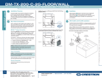
DO GUIDE
DO Check the Box
QTY PRODUCT
COLOR
PART NUM.
DM-RMC-200-C
DigitalMedia 8G+® Receiver and Room Controller 200
2
Connector, 2-Pin
2003574
4
Connector, 2-Pin
2003582
2
Connector, 4-Pin
2003576
DO Install the Device
1
Connector, 5-Pin
2003577
1
Power Cord, 5' 10" (1.78 m)
2042043
1
Power Pack, 24 Vdc 2.5 A, 100-240 Vac
1
Screw, 6-32 x 1/2”, Pan Head, Phillips
Black
2007238
4
Screw, 6-32 x 1”, Pan Head, Phillips
Black
2007250
4
Screw, 6-32 x 3/4", Truss Head, Combo
2009211
1
Bracket, Support
2042429
The Crestron® DM-RMC-200-C mounts into a 2-gang electrical box using the included support
bracket. The support bracket provides a holder for the included power pack.
Mounting the Device into an Electrical Box
To mount the device into an electrical box, do the following:
1. Using the four included 6-32 x 3/4” combo truss head screws, attach the included support
bracket to the electrical box.
2
Tie Wrap, Cable Tie, 15 1/2" x 1"
2041865
Black
2013608
Not Included: Cables
3. Using the four included 6-32 x 1” Phillips pan head screws, attach the DM-RMC-200-C to
the support bracket.
2. Ground the DM-RMC-200-C and attach the proper cables to the back of the unit.
Ground
Amplified Stereo
Audio Output
Inserting the Power Pack into the Power Pack Holder
To insert the power pack into the power pack holder, do the
following:
1. Position the power pack between the left and right
flanges and behind the bottom flange of the power pack
holder.
To Relay
Controllable
Devices
Software
Programmable
Digital Input
From DM® Switcher,
Transmitter, or
Other DM Device or
from HDBaseT®
Device1
2. Using the included 6-32 x 1/2” Phillips pan head screw,
thread the screw through the hole in the top flange of the
power pack holder to hold the power pack in place.
3. Using one of the included tie wraps, thread the tie wrap
through the hole in the right flange of the power pack
holder, and then fasten the tie wrap to the power pack
cable.
Tie Wrap
Hole
Installation of the power pack in the holder appears as shown
below.
Rear Panel Connections
LAN:
AUDIO OUT R, L
AUDIO OUT R, L
10BASE-T/
(LINE):
(SPEAKER): Stereo Unbalanced 100BASE-TX
Amplified Stereo
Ethernet to Local
Line Level
Audio Output
Audio Output Network Device
24 V
2.5A MAX:
From Power
Pack (Included)
NOTE: Connection to the power pack is not required when
PoDM is used to power the device.
DO Make Additional
Connections to the Device
Make additional connections as appropriate for the application.
Front Panel Connections
HDMI OUT:
HDMI® Digital
Video/Audio
Output
DIG IN:
Software
Programmable
Digital Input
The configuration of the receiver within the DigitalMedia 8G+®
system determines how the IP address of the receiver is set:
•• If the receiver connects to a DigitalMedia™ switcher, the
receiver is configured by the switcher automatically.
COM:
To RS-232
Device
USB HID:
From USB
HID-Compliant
Device
DO Set the IP Address
IR:
To IR
Controllable
Device
•• If the receiver connects to a DigitalMedia 8G+ transmitter,
the receiver uses its own configuration settings. By default,
DHCP (Dynamic Host Configuration Protocol) is enabled.
If desired, you can assign the default IP address to the
receiver by holding down the SETUP button while the unit
boots up. The default IP address overwrites the current
setting. The default IP address of the DM-RMC-200-C is
192.168.1.245. To manually set a different IP address, use
Crestron Toolbox™.
As of the date of manufacture, the product has been tested and found to comply with specifications for CE marking.
This product is Listed to applicable UL Standards and requirements by Underwriters Laboratories Inc.
Federal Communications Commission (FCC) Compliance Statement
This device complies with part 15 of the FCC Rules. Operation is subject to the following two conditions:
(1) This device may not cause harmful interference, and (2) this device must accept any interference received, including interference
that may cause undesired operation.
CAUTION: Changes or modifications not expressly approved by the manufacturer responsible for compliance could void the
user’s authority to operate the equipment.
NOTE: This equipment has been tested and found to comply with the limits for a Class B digital device, pursuant to part 15 of the
FCC Rules. These limits are designed to provide reasonable protection against harmful interference in a residential installation.
This equipment generates, uses and can radiate radio frequency energy and, if not installed and used in accordance with the
instructions, may cause harmful interference to radio communications. However, there is no guarantee that interference will not
occur in a particular installation.
DO GUIDE
1. The DM IN port is a PoDM (Power over DM) or PoH (Power over HDBaseT)
PD (Powered Device) port. To receive PoDM or PoH, the DM-RMC-200-C
requires a connection to a DigitalMedia switcher or other equipment that
has a PoDM or PoH PSE (Power Sourcing Equipment) port. Any wiring that
is connected to a PoDM or PoH PSE port is for intra-building use only and
should not be connected to a line that runs outside of the building in which
the PSE is located.
DO Learn More
Visit the website for additional information and the
latest firmware updates.
Crestron Electronics
15 Volvo Drive, Rockleigh, NJ 07647
888.CRESTRON | www.crestron.com
If this equipment does cause harmful interference to radio or television reception, which can be determined by turning the
equipment off and on, the user is encouraged to try to correct the interference by one or more of the following measures:
•• Reorient or relocate the receiving antenna
•• Increase the separation between the equipment and receiver
•• Connect the equipment into an outlet on a circuit different from that to which the receiver is connected
•• Consult the dealer or an experienced radio/TV technician for help
Industry Canada (IC) Compliance Statement
CAN ICES-3(B)/NMB-3(B)
The specific patents that cover Crestron products are listed at patents.crestron.com.
The product warranty can be found at www.crestron.com/warranty.
Crestron, the Crestron logo, Crestron Toolbox, DigitalMedia, DigitalMedia 8G+, and DM are either trademarks or registered trademarks of Crestron Electronics, Inc. in the United States and/
or other countries. HDBaseT and the HDBaseT Alliance logo are either trademarks or registered trademarks of the HDBaseT Alliance in the United States and/or other countries. HDMI and the
HDMI logo are either trademarks or registered trademarks of HDMI Licensing LLC in the United States and/or other countries. Other trademarks, registered trademarks, and trade names may
be used in this document to refer to either the entities claiming the marks and names or their products. Crestron disclaims any proprietary interest in the marks and names of others. Crestron
is not responsible for errors in typography or photography.
This document was written by the Technical Publications department at Crestron.
©2015 Crestron Electronics, Inc.
DOC. 7549A (2042263) 05.15
Specifications subject to change without notice.