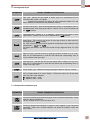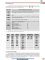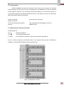
1
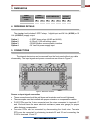
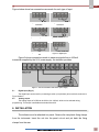
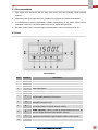
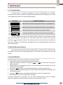
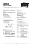
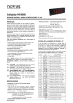
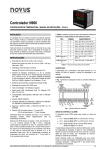
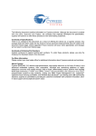
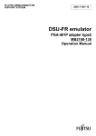
A1500 Universal Process Indicator User Manual ABUS TECHNOLOGIES INC. A1500 WARNING This manual should be passed on to the end user. The contents of this manual are subject to change without prior notice. All rights reserved. ABUS gives no warranty of any kind with regard to this manual, including, but not limited to, fitness for a particular purpose. If any question arises or errors are found, or if any information is missing from this manual, please inform your supplier or inform at [email protected]. The specifications mentioned in this manual are limited to those for the standard type under the specified model number break-down and do not necessarily apply for customized instruments. Please note that changes in the specifications, construction, or component parts of the instrument may not immediately be reflected in this manual at the time of change. If the customer or any third party is harmed by the use of this product, ABUS assumes no responsibility for any such harm owing to any defects in the product which were not predictable, or for any indirect damages. The integral modules specifically HART module are not manufactured by ABUS. Although Warning hazards are related to personal injury, and Caution hazards are associated with equipment or property damage, it must be understood that operation of damaged equipment could, under certain operational conditions, result in degraded process system performance leading to personal injury or death. Therefore, comply fully with all Warning and Caution notices. Information in this manual is intended only to assist our customers in the efficient operation of our equipment. Use of this manual for any other purpose is specifically prohibited and its contents are not to be reproduced in full or part without prior approval of Technical Communications Department, ABUS Technologies HEALTH AND SAFETY To ensure that our products are safe and without risk to health, the following points must be noted: 1. The relevant sections of these instructions must be read carefully before proceeding. 2. Warning labels on containers and packages must be observed. 3. Installation, operation, maintenance and servicing must only be carried out by suitably trained personnel and in accordance with the information given. Any deviation from these instructions will transfer the complete liability to the user. 4. Normal safety precautions must be taken to avoid the possibility of an accident occurring when operating in conditions of high pressure and/or temperature. 5. Chemicals must be stored away from heat, protected from temperature extremes and powders kept dry. Normal safe handling procedures must be used. 6. When disposing of chemicals ensure that no two chemicals are mixed. Safety advice concerning the use of the equipment described in this manual or any relevant hazard data sheets (where applicable) may be obtained from the Company address on the back cover, together with servicing and spares information. ABUS TECHNOLOGIES INC. 2 A1500 . CATALOGUE Contents Page No. 1. Introduction 4 2. Presentation 4 4 Technical Parameters 3. Dimensions 5 4. Ordering Details 5 5. Connections 5 6. Installation 6 7 7 8 9 9 12 1. Recommendation 2. Panel 3. Alarm 7. Configuration 1. Programming the Indicator 2. Serial Communication 8. Operation 1. Configuration Protection 2. Special Functions 9. Maintenance 1. Troubleshooting 2. Special Recommendation 3. Input Calibration 14 14 15 16 16 16 16 10. Safety Precautions 17 11. Warranty 17 ABUS TECHNOLOGIES INC. 3 A1500 1. INTRODUCTION A1500 is a universal process indicator which accepts a large variety of input signals and sensors. A six-digit LED display shows measured value and all programming parameters. Instrument configuration is achieved from the keyboard, without any hardware change. Thus, the selection of input type and type of alarms action, besides other special functions, are accessed and defined from the frontal keyboard. The user should read this manual thoroughly before using the instrument. It must be handled with care and should be used accordingly for best results. 2. PRESENTATION Technical Parameters Power: 85 to 265Vac/dc, 50/60 Hz (basic model); 24 Vdc/ac, optional; Maximum consumption: VA Relays: ALM1 and ALM2: SPDT - 3A / 250Vac (3A / 30Vdc); ALM3 and ALM4: SPST – NA 3A / 250Vac (3A / 30Vdc) (optional); All input signals are factory calibrated. Thermocouples are calibrated according to NBS standards (NBR12771), RTD’s NBR 13773/97 (IEC-751), (=0.00385). Internal resolution: 128000 levels, Display resolution: 62000 levels (-31000 to 31000) Sampling rate: 5 measurements per second for TC and RTD measurements for 0-50mA, 4-20mA, 0-5V, 0-10V Accuracy: Thermocouples J, K, T, N: ± 0.25% of full scale +1°C. Thermocouples E, R, S, B: ± 0.25% of full scale +3°C. Pt100: 0.2% of full scale Current or voltage: 0.15% of full scale Cold junction compensation error: ± 1 °C Warm up time: 15 minutes Input impedance: 0-50mV, Pt100 and T/C: >10M 0-5V, 0-10V > 1M 4-20mA: 15 3-wire circuit, 750A excitation current. Pt100 measure: PV retransmission resolution: 4000 levels, 550max. Working conditions: 0 to 55°C, 35 to 85% relative humidity. Front panel: IP65, Polycarbonate UL94 V-2; Back panel: IP30, ABS+PC UL94 V-0; Weight: 240g basic version; 265g with options Dimension: 48×96×92 mm Panel cut out: 45×93mm ABUS TECHNOLOGIES INC. 4 A1500 3. DIMENSIONS PANEL DIMENSION PANEL DIMENSION CODE A1500 CASE DIMENSION W H W H D 96 48 90 44 100 HOLE CUTOUT DIMENSION W H 92 45 4. ORDERING DETAILS The standard unit includes 2 SPDT relays, 1 digital input and 24 Vdc (A1500) or 10 Vdc (A1500LC) supply output. Option 1 Option 2 Option 3 Option 4 : 2 SPST alarm relays (ALM3 and ALM4). : 4-20 mA / 0-20 mA analog output. : RS485 Modbus communication interface. : 24 Vac/Vdc power supply input. 5. CONNECTIONS The internal electronics can be removed from the front panel without any cable disassembly. The input signals and power connections are shown in Figure 2. Figure 2 – Back Panel Terminals Sensor or input signal connection These connections should be well done and terminals must be well tightened. Thermocouples must be installed with proper extension or compensation cables. Pt100 RTDs must be 3-wire connected and the wires connected to terminals 17 and 18 should have the same electrical resistance (same wire gauge) for proper cable distance compensation. Four-wire RTDs can be connected by disconnecting the fourth wire. Two-wire RTDs can be connected by shortening terminals 22 and 23 and connecting the Pt100 to terminals 16 and 17. ABUS TECHNOLOGIES INC. 5 A1500 Figures below show how connections are made for each type of input. Figure 3 – Thermocouple Connection Figure 4 – 3 wire Pt100 Connection Figure 5 – Voltage Connection Figure 6 – Current Connection Figure 7 – Connection for 010V Figure 8 – Digital Input Figure 9 shows connections made to measure signals from a 4-20mA transmitter supplied by the 24 V power supply, the indicator provides. Figure 9 – Two-wire transmitter with internal power supply 5.1 Digital Input (Dig In) The digital input can be used by connecting a switch (or equivalent) to its terminals, as shown in Figure 8 above. 5.2 Analog output The analog output of A1500 can be 0-20 mA or 4-20mA, which can be selected during programming. This output is available at terminals 29 and 30. 6. INSTALLATION The indicator must be attached to a panel. Remove the two plastic fixing clamps from the instrument. Insert the unit into the panel cut-out and put back the fixing clamps from the rear. ABUS TECHNOLOGIES INC. 6 A1500 6.1 Recommendation 1. Input signal wires should be laid out away from power lines and preferably inside grounded conduits. 2. Instrument mains (line) supply should be suitable for this purpose and should not be shared. 3. In controlling and monitoring applications, possible consequences of any system failure must be considered in advance. The internal alarm relay dos not warrant total protection. 4. RC filters (47 and 100nF, serial) are highly recommended for valve and contactor coils, etc. 6.2 Panel Panel Attribute S.No. Parameters Description 1 2 3 4 5 6 A1 A2 A3 A4 Rx Tx 7 P Program Key: This key is used to access different displays with the programmable parameters of the device. 8 ◄ Back Key: This key is used to go back to the previous parameter displayed in the menu cycle. 9 ▲ UP / MAX Key: This key is used to increase parameter value, as well as to display maximum values stored in memory. 10 ▼ DOWN / MIN Key: This key is used to decrease parameter value, as well as to display minimum values stored in memory. 11 F This special function key is used for pre-programmed functions as explained in the SPECIAL FUNCTION KEY section of this manual. 12 Display Show active alarms. Show active alarms. Show active alarms. Show active alarms. Indicate RS485 communication line is active. Indicate RS485 communication line is active. Shows the process variable (PV) and the programming prompts. ABUS TECHNOLOGIES INC. 7 A1500 6.3 Alarm 6.3.1 Alarm Functions The alarms can be set to operate in seven different functions. These functions are shown in table 2 and described below. The alarm can also be set as disabled. Sensor break – Ierr The alarm is triggered whenever the sensor breaks or is badly connected. Low alarm – Lo The alarm relay is triggered whenever the measured value is below the alarm set point. High alarm - Ki The alarm relay is triggered whenever the measured value is above the alarm set point. Differential low – Dif.lo Deviation alarm: Alarm relay is triggered whenever the difference (deviation) between the value measured and the reference value (AlrEF) is beyond values defined in SP.AL. For this function, the triggering point is defined as: (ALrEF – SP.AL) Differential high – Dif.ki Deviation alarm: Alarm relay is triggered when the difference (deviation) between the value measured and the reference value (AlrEF) is beyond values defined in SPAL. For this function, the triggering point is defined as: (ALrEF + SP.AL) Differential (or Band) out of range – Dif.ov Deviation alarm: Alarm relay is triggered when the difference (deviation) between the measured value and the reference value (AlrEF) is higher than the value defined in SPAL. For this function, the triggering points are defined as: (ALrEF – SP.AL) and (ALrEF + SP.AL) Differential (or Band) within range – Dif.In Deviation alarm: Alarm relay is triggered when the difference (deviation) between the measured value and the reference value (AlrEF) is lower than the value defined in SPAL. For this function, the triggering points are defined as: (ALrEF – SP.AL) and (ALrEF + SP.AL) 6.3.2 Alarm Timer The alarms can be configured in the alarm timer. The user can set delays in the alarm action, define just one pulse for an alarm event, or make the alarm work in the form of sequential pulses. Table 3 shows these advanced functions. Times T1 and T2 can be programmed from 0 to 6500 seconds (refer to item 8.2). Set 0 (zero) at the T1 and T2 to prompt for a normal non-timer alarm operation. The LED lights will flash whenever there is an alarm condition regardless of the current alarm status which may be temporarily off because of the timer action. 6.3.3 Alarm Initial Blocking The initial blocking option inhibits the alarm from being recognized if an alarm condition is present when the controller is first energized. The alarm will be triggered only after the occurrence of a ABUS TECHNOLOGIES INC. 8 A1500 non alarm condition followed by a new occurrence for the alarm. The initial blocking is disabled for the sensor break alarm function. ADVANCED FUNCTION T1 T2 Normal Operation 0 0 Delayed 0 1s to 6500s Pulse 1s to 6500s 0 Oscillator 1s to 6500s 1s to 6500s ACTION 7. COFIGURATION 7.1 Programming the Indicator 7.1.1 Work Cycle This is the first cycle. At power up the indicator will display the Process Variable (PV). The alarm triggering points are also displayed at this cycle (alarm Set-points). To run through this cycle just press the P key. PARAMETERS PROMPT PARAMETER DESCRIPTION 8.8.8.8.8. Measure. Shows the measured variable. For Pt100 or thermocouples the display will show the absolute temperature value. For 4-20mA, 0-50mV, 0-5V and 0-10mV inputs the display shows the values defined in the”in.LoL” and “in.kiL” prompts. With the hold function programmed the display shows the frozen variable and alternates with the message “koLd”. Likewise, with Peak Hold function programmed the high limit is displayed with the “P.koLd” prompt alternately. Should any fault situation occur the indicator will display an error message which can be identified at item 11 of this manual? Al.ref Differential Alarm Reference Value - This prompt is shown only when there is an alarm programmed with differential function. Value used as a reference for differential alarms triggering. Sp.al1 Sp.al2 Sp.al3 Sp.al4 Set Points of Alarms 1, 2, 3 and 4 - Defines the operation point of each alarm programmed with “Lo” or “ki” functions. When the alarms are programmed with differential function, the alarm set point value represents the deviation value of these alarms. ABUS TECHNOLOGIES INC. 9 A1500 7.1.2 Alarm Cycle PARAMETERS PROMPT PARAMETER DESCRIPTION fV.al1 fV.al2 fV.al3 fV.al4 Alarm Function - Defines the alarms 1, 2, 3 and 4 function, as defined in item 4.1 oFF : Alarm off iErr : Broken or Shorted Sensor Lo : Low value ki : High value DiF.Lo : Differential low DiF.Hi : Differential high DiF.ov : Differential out of range DiF.in : Differential within range Ky.al1 Ky.al2 Ky.al3 ky.al4 Alarm Hysteresis This is the difference from the measured value to the point where the alarm is turned ON and OFF. Bl.al1 Bl.al2 Bl.al3 bl.al4 Alarm Blocking Should any alarm condition occur, each alarm can be disabled when energizing the indicator? Refer to item 4.3. Al1t1 Al1t2 Al2t1 Al2t2 Al3t1 Al3t2 Al4t1 Al4t2 Alarm Timer The user can set delayed, momentarily or sequential alarms as shown in table 3 by defining times T1 and T2. To disable this function just set zero for T1 and T2. 7.1.3 Function Cycle PARAMETERS f.fvnc Dig.in PROMPT PARAMETER DESCRIPTION F KEY FUNCTION – Defines functions for F Key. Options are oFF - Key not used. Hold - Hold PV RSt - Resets Peak and Valley P.koL - Peak Hold These functions are described in item 5.2. Digital Input Function – Defines the function for the digital input. Options are: oFF - kold - rESEt - PkoLd Refer to item 5.2. filtr Input Digital Filter - Adjustable from 0 to 20, this is used to reduce instability of the measured value. 0 means the filter is off and 20 means maximum filtering. The higher the filter value the lower is the measured value response. ofset Display Offset - This a value which is added to the PV to offset any measurement deviation or sensor error. The offset is shown directly in the programmed engineering unit. For °F measurements the null reference is at 32°F. bavd Adres Baud Rate - Serial digital communication speed in bps. Programmable: 1200, 2400, 4800, 9600, 19200, 38400 and 57600 bps. Communication Address - A number that identifies the instrument in a multidrop network. ABUS TECHNOLOGIES INC. 10 A1500 7.1.4 Configuration Cycle PARAMETERS In.typ Dp.pos PROMPT PARAMETER DESCRIPTION Input Type - Selects the input signal or sensor type to be connected to the PV terminals. Refer to table 1 for options. Changing this parameter will change all other parameters related to PV and alarms, therefore it should be the first parameter to be set. Decimal Point Position - Defines the decimal point position in the displayed value. It is displayed when linear input types 0-50mV, 4-20mA, 0-5V or 0-10V are selected at the “in.tYP” prompt. Vnit Temperature Unit - Selects °C or °F indication. This prompt is not shown for input types 0-50mV, 4-20mA, 0-5V or 0-10V is selected at the “in.tYP” prompt. s.root Square Root - This prompt is only shown for input type 0-50mV; 4-20mA and 0-5V are selected at the “in.tYP” prompt. Set “YES” and the square root will be applied to the measured value within the limits programmed in “in.LoL” and “in.kiL”. The display will show the low limit value should the input signal be below 1% of the range. In.lol Input Low Limit - Sets the low limit for input type 0-50mV, 4-20mA, 0-5V or 0-10V. When the PV Retransmission is used this limit defines the corresponding 4mA (or 0mA) in relation to the input value. In.kil Input High Limit - Sets the high limit for input type 0-50mV, 4-20mA, 0-5V or 0-10V. When the PV Retransmission is used this limit defines the corresponding 20mA in relation to the input value. Ovt.ty Analog Output Type - Selects the analog output type to either 0- 20mA or 4-20mA. Ovt.er 4-20 mA Output behavior in case of failures – Defines the output as 4-20 mA when there is an error in the indication. Do – Applies a value < 4 mA; UP – Applies a value > 20 mA 7.1.5 Customized Linearization Cycle PARAMETERS PROMPT PARAMETER DESCRIPTION Inp.01 Inp.20 Defines the extreme points (lower and upper) of the customized linearization. Values must be in the input signal unit: 0-50 mV, 4-20mA or 0-5V. For 0-10V select 0-5V. Ovt.01 ovt.20 Defines the proportional indications in respect to each segment of the customized linearization. Values are in desired indication unit (within the Indication Lower and Upper Limits). ABUS TECHNOLOGIES INC. 11 A1500 7.1.6 Calibration Cycle All input types are factory calibrated. Should it be required, calibration should only be done by experienced personnel. If this cycle is accidentally accessed do not touch the or keys. Just go through all cycles until the display shows the main or operation menu. PARAMETERS In.lo( In.ki( PROMPT PARAMETER DESCRIPTION Input Low Calibration - Sets the Process Variable low calibration (offset). Several key strokes at or might be necessary to increment one digit. Input High Calibration - Sets the Process Variable span calibration (gain). Ov.lo( Analog Output Low Calibration - Sets the analog current output low calibration (offset). Ov.Ki( Analog Output Span Calibration - Sets the analog current output high calibration (span) of the analog output (20mA). (J lo Cold Junction Calibration - Allows the user to adjust this calibration directly in degrees, of temperature in the indicator terminals. k.type Hardware Type - These parameters adapt the software to the hardware available and should not be changed by the user. 2 Alarms 3 2 Alarms and 4-20 mA 19 2 Alarms and RS485 35 2 Alarms, 4-20 mA and RS485 51 4 Alarms 15 4 Alarms and 4-20 mA 31 4 Alarms and RS485 47 4 Alarms, 4-20 mA and RS485 63 The table below shows the sequence of cycles and parameters presented in the indicator display. There are parameters that must be defined for each alarm available: Work Cycle Alarm Cycle Function Cycle Configuration Cycle Customized Linearization Cycle Calibration Cycle 8.8.8.8.8. Fv.al1 f.fvn( In.typ Inp.01 -inp.30 In.lo( Al.ref Df.al1 Dig.in Dp.pos OVt.01 - ovt.30 In.ki( Sp.al1 Ky.al1 Filtr Vnit Ov.lo( Bl.al1 Ofset Sroot Ov.ki( Al.1t1 Bavd In.lol (j lo Al.1t2 adres In.kil k.type OVT.TY OVT.er 7.2 Serial Communication The indicator can be supplied with an asynchronous RS-485 digital communication interface for master-slave connection to a host computer (master). The indicator works as a slave only and all commands are started by the computer which sends a request to the slave address. The addressed unit sends back the requested reply. Broadcast commands (addressed to all indicator units in a multi-drop network) are accepted but no reply is sent back in this case. ABUS TECHNOLOGIES INC. 12 A1500 7.2.1 Characteristics RS-485 compatibility with two-wire connection, from the host is up to 31 slaves in a multi-drop network topology. And Up to 247 units can be addressed by the MODBUS RTU protocol. Maximum network distance: 4,000 feet. Time of indicator disconnection: Maximum of 2ms after the last byte. Te communication signals are electrically isolated from the rest of the instrument, and can be 1200, 2400, 4800, 9600, 19200, 38400, and 57600 bps. Number of data bits: 8, without parity or pair parity Number of stop bits: 1 Time to start response transmission: Up to 100ms after acknowledging the command. Protocol: MODBUS (RTU) 7.2.2 Rs485 Interface: Electrical Connection RS-485 signals are: D1= D: D0= D: C = GND: Bidirectional data line Inverted bidirectional data line Ground Optional connection to improve communication performance Figure 11 shows an example of an RS-485 network. If the computer does not have an RS-485 port available an external RS232RS485 converter should be used. Figure 11 - RS-485 network connection ABUS TECHNOLOGIES INC. 13 A1500 8. OPERATION For best results, this indicator requires correct setting of parameters as input type (T/C, Pt100, 4-20mA, etc), alarms triggering point, alarm function, etc. These parameters are divided in five levels or groups of parameters which we will refer to as Cycles. S.NO. CYCLE ACCESS 1 2 3 4 Work Alarms Functions Configuration Customized Linearization Calibration Free Access 5 6 Reserved Access Table-4: Parameter Cycles The work cycle has free access. All other cycles require a certain combination of key strokes to be accessed. The combination is and simultaneously within the cycle chosen, just press keys, when pressed to go to the subsequent parameters of this cycle. At the end of each cycle the display will go back to the work cycle. After reaching the intended prompt just press or key to change this parameter accordingly. All changes are recorded in non-volatile memory as we move to next prompt. After 25 seconds with no key pressed the indicator will return to the measuring cycle (work cycle). 8.1 Configuration Protection As safety measure, changes can be prevented by a combination of keys for each cycle. The protected parameters could be still viewed but not changed. To protect a cycle, just press and keys simultaneously for 3 seconds, at the beginning of the referred cycle. To unlock this cycle just press the same keys again for 3 seconds. The display will briefly flash confirming that the cycle was locked or unlocked. For further protection, the unlock operation through the keypad may be disabled by changing the position of an internal strap inside the indicator: When PROT is OFF, the user is allowed to lock and unlock the cycles using the keypad as explained above. If PROT is ON, the cycles lock/unlock operation is disable. ABUS TECHNOLOGIES INC. 14 A1500 8.2 SPECIAL FUNCTIONS 8.2.1 Maximum and Minimum The indicator memorizes the measured maximum and minimum values (peak and valley). These two values are shown by pressing either the MAX or MIN keys. Pressing both keys simultaneously will clear the memory for a new peak and valley detection. 8.2.2 Special Function Key and Digital Input The F key (special function key) in the frontal panel and the optional digital input can execute special functions according to the user selection. Figure 8 shows how to activate the digital input. The special functions for the F key and for the digital input are explained as it follows. KOLD - FREEZE MEASURED VALUE The hold function freezes the measured value showed in the display. Each time the F key or the digital inputs are selected, alternates from hold to normal mode. Whenever the indicator is in the hold mode a “koLd” message is briefly displayed to show the operator that the displayed value is the frozen value and not the present reading. PKOLD - MAXIMUM VALUE The Peak Hold function shows the maximum value measured since the last time the F key was pressed or the digital input activated. Each activation of the F key or digital input triggers a new Peak Hold cycle and the display resets with a new peak value. RESET - CLEARS MAXIMUM AND MINIMUM This function works the same way as the MAX and MIN keys pressed simultaneously, as explained in the 5.1 section. If this “reset” function is programmed, every touch of the F key or activation of the digital input will clear the memory and a new cycle of maximum and minimum values memorization will start. 8.2.3 Process Variable Retransmission As an option, the indicator can be supplied with an isolated 0-20mA or 4-20mA analog output for Process Variable (PV) retransmission. The PV values that define the range of the 0mA/4mA to 20mA retransmission can be programmed by the user in the high and low indication limits, at configuration level. When this option is available, retransmission will be always active, so that the user will not be required to turn it on or off. For a voltage output signal an external shunt (calibrated resistor) should be installed at the analog output terminals. 8.2.4 Extra 24 Vdc Power Supply – Extra P.S The indicator provides a voltage power supply of 24 Vdc to excite the field transmitters with 25 mA current capacity. It is available at the 16 and 17 terminals at the back panel. 8.2.5 Customized Linearization Three types of signals can be user-customized to fit special linearization profiles. This means that the operator can configure the instrument to read non-standard crescent non-linear signals with high accuracy. ABUS TECHNOLOGIES INC. 15 A1500 9. MAINTENANCE 9.1 Troubleshooting Connection errors or improper configuration will result in malfunctioning of the indicator. Carefully revise all cable connections and programming parameters before operating the unit. Some error messages will help the user identify possible problems. MESSAGE POSSIBLE PROBLEM Measured value is above the programmed sensor or input signal limit. Measured value is below the programmed sensor or input signal limit. Open input. No sensor is connected or the sensor is broken. Pt100 cable resistance is too high or the sensor is badly connected. Different messages other than the ones above should be reported to the manufacturer. Please inform the serial number if this should occur. The serial number can be viewed at the display by pressing the key for about 3 seconds. The software version of the instrument can be viewed at the time the unit is powered. The instrument might display false error messages especially concerning the type of input selected. 9.2 Special Recommendations Should the indicator be repaired, some special handling care should be taken. The device must be withdrawn from the case and immediately placed in an anti-static wrap; protected from heat and humidity. 9.3 Input Calibration Should calibration of some scale be necessary, proceed as it follows: 1. Program the indicator with the type of input requiring calibration; 2. Program the high and low limits of the measure (in.lol and in.kil) for the extreme of the type of input programmed; 3. Assign the input a corresponding signal and a know indication/measure and slightly over the low limit of the indication/measure; 4. Access the “inLo“parameter. Use the MIN and MAX keys to select the expected values; 5. Assign the input a corresponding signal and a known indication and slightly below the higher limit of the indication/measure; 6. Access the “inki“parameter. Use the MIN and MAX keys to select the expected values; 7. Repeat steps c to f until no new adjustment is necessary. Note: When verifications are preceded, note if the Pt100 excitation/activation current the calibrator requires is compliant to the Pt100 excitation current used in this instrument: 750µA. ABUS TECHNOLOGIES INC. 16 A1500 10. SAFETY PRECAUTIONS 1. The unit should be powered for 15 minutes before use. 2. Use in ambient temperature of 0-60˚C. 3. Avoid vibrations, shock, excessive dust, corrosive chemical materials or gaseous environment. 4. Input wire should not be too long. If measured signal have to be far away from the unit, please use 2-core shielded cable. 5. Use this instrument in the scope of its specifications, otherwise fire or malfunctions may result. 6. Contact of the instrument, with organic solvents or oils should be avoided. 7. Do not turn on the power supply until all of the wiring is completed. Otherwise electrical shock, fire or malfunction may result. 8. Do not disassemble, repair or modify the instrument. 9. All connections should be tightened properly. 10. Power supply should be constant, should not be fluctuating. 11. WARRANTY ABUS provides the original purchaser of this instrument a one (1) year warranty against defects in material and workmanship under the following terms: The one year warranty begins on the day of shipment as stated on the sales bill. During the warranty period all costs of material and labor will be free of charge provided that the instrument does not show any evidence of misuse. For maintenance, return the instrument with a copy of the sales bill to our factory. All transportation and insurance costs should be covered by the owner of the equipment. Should any sign of electrical or mechanical shock, abuse, bad handling or misuse be evident the warranty voids and maintenance costs will be charged. ABUS TECHNOLOGIES INC. www.abustek.com, E-Mail: [email protected] ABUS TECHNOLOGIES INC. 17